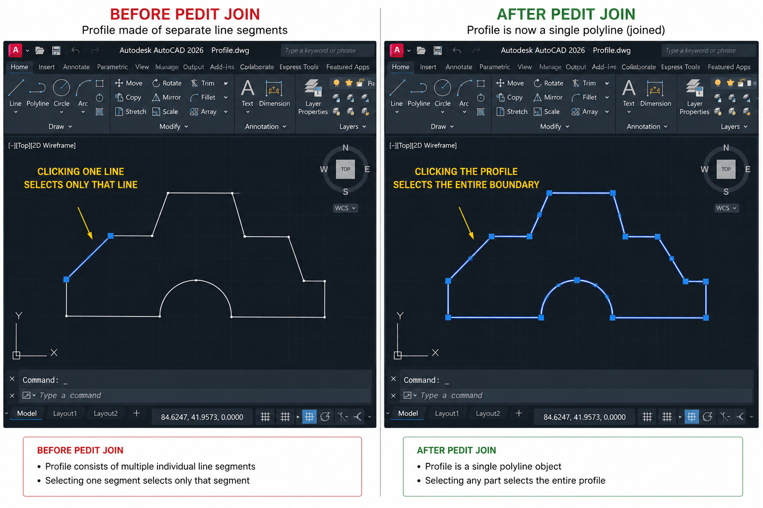
You have drawn a 2D outline in AutoCAD. Maybe it is the cross-section of a mechanical part. Maybe it is an architectural wall layout, a swept path profile, or the silhouette of a component from an engineering drawing. Now you need to turn that flat outline into a 3D solid with actual volume, mass, and surfaces. This is one of the most fundamental workflows in AutoCAD 3D modelling, and it is also one of the most commonly broken.
The breaking point is almost always the same: the profile outline. AutoCAD’s solid creation commands — EXTRUDE, REVOLVE, LOFT, SWEEP — all have one non-negotiable requirement: the profile must be a closed, valid 2D boundary. A profile that looks closed visually is not always closed geometrically. Individual lines and arcs that appear to touch often have tiny gaps between their endpoints. Profiles drawn with separate line segments rather than a single polyline frequently fail silently, producing surfaces instead of solids or generating an error message that gives no useful guidance on how to fix it.
This guide covers the complete workflow from profile outline to finished 3D solid: how to create profiles correctly from scratch, how to diagnose and fix problem profiles that refuse to extrude, which command to use for which type of profile, how to handle complex profiles with holes and nested shapes, and a full troubleshooting reference for every common failure mode. It is the guide that should exist at the start of every AutoCAD 3D modelling tutorial but usually does not.
| Quick Answer: To make a 3D solid from a profile outline in AutoCAD: (1) Ensure the profile is a single closed polyline or REGION. Use PEDIT > Join to combine separate lines/arcs, or BOUNDARY to auto-detect and create a closed polyline from intersecting geometry. (2) Set the correct UCS so the profile is on the right plane. (3) Type EXT (EXTRUDE), select the profile, press Enter, and enter the depth. AutoCAD creates the 3D solid. |
What Is a Profile in AutoCAD 3D Modelling?
In AutoCAD 3D modelling, a profile is a 2D geometric boundary that defines the cross-section, outline, or path of a 3D feature. The profile is the foundation: it defines the shape, and the solid creation command (EXTRUDE, REVOLVE, LOFT, or SWEEP) gives it depth, revolution, or direction to produce a 3D solid.
Understanding profiles correctly is the single most important prerequisite for successful 3D modelling in AutoCAD. Nearly every 3D modelling failure at the beginner and intermediate level traces back to a profile problem: the profile is not closed, it is not on the right plane, it contains multiple overlapping objects, or it is made up of separate line segments rather than a unified boundary.
The relationship between a profile and the 3D solid it produces is direct and deterministic: change the profile and the solid changes with it. This is why getting the profile exactly right before invoking any solid creation command is essential. It is always faster to spend an extra two minutes verifying the profile than to debug a solid that has extruded incorrectly and needs to be rebuilt.
Profile Types: What AutoCAD Accepts and What It Rejects
Not all 2D objects can serve as profiles for solid creation commands. The following table defines exactly what each major solid creation command accepts, what it rejects, and the consequence of using an invalid profile.
| Profile Object Type | Valid for EXTRUDE? | Valid for REVOLVE? | Valid for LOFT? | Valid for SWEEP? | Result if Open |
| Closed POLYLINE (single object) | Yes | Yes | Yes (cross-section) | Yes | N/A – polyline must be closed first |
| Open POLYLINE | Yes (creates surface) | Yes (creates surface) | Yes (creates surface if all open) | Yes (creates surface) | Creates a surface, not a solid |
| REGION (from closed boundary) | Yes | Yes | Yes | Yes | N/A – REGIONs are always closed |
| CIRCLE | Yes (always closed) | Yes | Yes | Yes | N/A – circles are always closed |
| RECTANGLE (drawn with REC command) | Yes (always closed) | Yes | Yes | Yes | N/A – rectangles are closed polylines |
| ELLIPSE | Yes (always closed) | Yes | Yes | Yes | N/A – ellipses are always closed |
| SPLINE (closed) | Yes | Yes | Yes | Yes | Creates surface if open |
| Individual LINES forming a shape | No (extrude fails) | No | No | No (individual lines only) | Individual lines cannot be used directly — must be joined first |
| Individual ARCS forming a shape | No (extrude fails) | No | No | No | Individual arcs cannot be used — must be joined into polyline or REGION |
| Mixed LINES and ARCS (separate) | No | No | No | No | Must be joined via PEDIT or converted to REGION |
| The Most Important Rule: AutoCAD’s solid creation commands require either a single closed object (closed polyline, circle, ellipse, closed spline, region) or a set of cross-sections for LOFT. They do not accept multiple separate objects that form a shape. The single most common reason EXTRUDE fails or creates a surface instead of a solid is that the profile consists of individual line and arc segments that look connected but are separate objects. The fix is always the same: join them first. |
Method 1: Drawing a Profile Correctly from Scratch
The cleanest, most reliable way to create a profile for 3D solid creation is to draw it as a single closed polyline from the beginning. A polyline drawn with the POLYLINE (PL) command is a single object whose segments are internally connected, making it inherently valid for extrusion without any post-processing.
Drawing a Straight-Sided Profile with POLYLINE
- Type PL (POLYLINE) and press Enter.
- Set the UCS correctly first: type UCS > W for World UCS to draw on the standard XY plane, or set the UCS to align with a specific face of an existing solid using UCS > F.
- With ORTHO on (F8), click the first corner of the profile.
- Type each side dimension and press Enter, changing direction at each corner. For a 100mm x 60mm rectangle: type 100, Enter (draws first horizontal segment); type 60, Enter (draws vertical); type 100, Enter (draws second horizontal); type C and Enter to close the polyline back to the starting point.
- The polyline is now a single closed object ready for EXTRUDE.
Drawing a Profile with Arcs and Straight Segments
Many engineering profiles mix straight edges with rounded corners or arcs. The POLYLINE command handles this with sub-options that switch between line and arc mode without ending the command:
- Type PL and Enter. Click the start point.
- Draw straight segments as normal. When you reach a segment that needs to be an arc, type A and press Enter to switch to Arc mode.
- In Arc mode, click the endpoint of the arc (AutoCAD creates a tangent arc by default). Type L and Enter to switch back to Line mode for the next straight segment.
- Continue alternating between arc and line mode as required by the profile shape.
- When back at the start point, type C and Enter to close. AutoCAD closes with a straight line or arc segment as appropriate.
| Pro Tip: For profiles with consistent fillets (rounded corners), it is usually faster to draw the profile with sharp corners as a closed polyline first, then use FILLET (F) in polyline mode to apply fillets to all corners at once. Type F (FILLET), type R and the fillet radius, press Enter, then type P and click the polyline. AutoCAD fillets every eligible corner simultaneously. |
Method 2: Fixing an Existing Profile with PEDIT Join
PEDIT (Polyline Edit) is the command used to repair, modify, and combine existing 2D geometry into a valid profile. Its Join option is one of the most useful tools in the entire AutoCAD 3D toolkit: it takes a collection of separate connected line and arc segments and welds them into a single closed polyline.
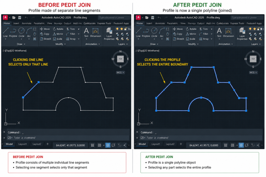
Use PEDIT Join whenever you are working with an existing 2D drawing where the profile was built from individual lines and arcs (as most 2D engineering drawings are) rather than a single polyline. Autodesk’s official guidance on converting lines to solids
Read Supporting Article: How to Draw a Line from Its Midpoint in AutoCAD
Full Step-by-Step: PEDIT Join
- Type PEDIT (or PE) and press Enter.
- AutoCAD prompts: Select polyline or [Multiple]:. If working with multiple separate objects, type M and press Enter to use Multiple mode.
- Select all the line and arc segments that make up your profile. Press Enter to confirm the selection.
- AutoCAD asks whether to convert non-polyline objects. Type Y and press Enter to convert all selected lines and arcs to polyline segments.
- AutoCAD prompts with edit options. Type J (Join) and press Enter.
- AutoCAD prompts: Specify fuzz distance or [Jointype]:. The fuzz distance is the maximum gap between segment endpoints that AutoCAD will bridge to join them. For clean drawings, the default (0 or a very small value) is fine. For drawings with tiny gaps, type a small value such as 0.001 and press Enter.
- AutoCAD joins the segments and reports how many segments were joined. Press Enter to accept and exit PEDIT.
- Type C (Close) as an additional PEDIT option if the joined polyline is not yet explicitly closed back to its start point.
What the Fuzz Distance Does: The fuzz distance in PEDIT Join defines the maximum gap between two segment endpoints that AutoCAD considers close enough to join. If two lines appear to meet but have a 0.5mm gap because OSNAP was off when they were drawn, setting the fuzz distance to 1 will bridge that gap. Setting it too high (e.g. 100) will join segments that were never meant to connect. Start with a small value and increase only if the join fails at a lower value.
Verifying the Join Was Successful
After PEDIT Join, click anywhere blank to deselect, then click the profile once. If it highlights as a single object (the entire outline becomes selected at once), the join was successful. If individual segments highlight separately, some joins were not made. Run PEDIT Join again on the un-joined segments, or investigate why those endpoints are not connecting using the endpoint OSNAP to check for gaps.
Method 3: Using REGION to Create a Profile from Any Closed Boundary
The REGION command converts any collection of connected objects that form a closed boundary — regardless of whether they are lines, arcs, polylines, splines, or a mix — into a single flat 2D region object. A region is essentially a solid surface with zero thickness. It is always treated as a closed boundary by AutoCAD’s solid creation commands, making it an extremely reliable alternative to polyline profiles.
When to Use REGION Instead of PEDIT
Use REGION when the profile boundary is made up of many different object types that cannot be easily joined with PEDIT (for example, a mix of splines, arcs, and lines). Also use REGION when you need to create profiles with holes (islands) — REGION supports Boolean operations between regions to create complex profiles with internal cutouts before extruding. This is covered in detail in the islands section below.
Full Step-by-Step: REGION Command
- Ensure all the objects forming the closed boundary are genuinely connected at their endpoints. Use OSNAP endpoint markers to verify that each connection is precise.
- Type REGION (or REG) and press Enter.
- Select all objects that form the closed boundary. Press Enter.
- AutoCAD reports: 1 loop extracted. 1 Region created. (The number will vary depending on how many closed loops you selected.)
- The selected objects are converted into a flat region object. The original line and arc geometry is replaced by the region.
- The region is now ready for EXTRUDE, REVOLVE, LOFT, or SWEEP.
| Important: REGION Replaces the Original Objects: When you run REGION, the original lines, arcs, and polylines are deleted and replaced by the region object. If you need to keep the original 2D geometry, copy it to a separate layer before running REGION, then set that layer to No Plot or freeze it after the region is created. |
Method 4: Using BOUNDARY to Auto-Detect Closed Areas
The BOUNDARY command is AutoCAD’s most automated profile creation tool. It works like the HATCH boundary detection algorithm: you click inside a closed area and AutoCAD automatically traces the boundary of that area, creating a new polyline or region on top of the existing geometry. The original geometry is preserved, and the new profile object is placed precisely on top of it.
BOUNDARY is particularly useful when you have a complex drawing with overlapping geometry and you want to create a clean profile from a specific enclosed area without manually selecting and joining all the boundary segments.
Full Step-by-Step: BOUNDARY Command
- Type BOUNDARY (or BO) and press Enter. The Boundary Creation dialogue opens.
- Under Object Type, choose Polyline (for a closed polyline profile) or Region (for a region profile). Polyline is the default and usually the better choice.
- Click Pick Points in the dialogue.
- Click inside the enclosed area whose boundary you want to trace. AutoCAD analyses the geometry and highlights the detected boundary.
- Press Enter to confirm. AutoCAD creates the new polyline or region object precisely on top of the detected boundary.
- The new profile is now a separate, clean, closed polyline or region ready for extrusion.
| BOUNDARY vs PEDIT Join — When to Use Each: Use PEDIT Join when you have a clearly defined set of connected segments that form your profile and you want to weld them into one polyline. Use BOUNDARY when the profile area is defined by intersecting geometry (lines that cross each other, overlapping shapes) and you want AutoCAD to auto-detect the enclosed area. BOUNDARY is faster and less error-prone for complex overlapping geometry. |
Validating Your Profile Before Extruding
Before invoking any solid creation command, always validate the profile. This five-step check takes under a minute and prevents the frustration of discovering problems after the solid has been generated incorrectly.
| Validation Check | How to Perform It | What It Confirms |
| Check object count | Click the profile once. Only ONE object should highlight. If multiple separate segments highlight, PEDIT Join or REGION is needed. | Profile is a single unified object, not multiple separate segments |
| Check closure | Type PEDIT, select the polyline. If the option ‘Close’ appears (rather than ‘Open’), the polyline is not explicitly closed. Type C to close it. | Profile endpoint connects back to start point — the polyline is geometrically closed |
| Check planarity | Type LIST, select the profile, press Enter. Check that all vertex Z coordinates are identical. If any differ, the profile is not flat and will extrude unpredictably. | Profile lies entirely on a single flat plane — no accidental Z deviations |
| Check for self-intersections | Zoom in and orbit around the profile. Look for any segments that cross each other within the boundary. | Profile boundary does not cross itself, which prevents solid creation |
| Test extrude direction | In the isometric viewport, check the UCS icon orientation. The extrusion will go perpendicular to the current UCS XY plane. Confirm this is the intended direction. | Extrusion will go in the correct direction relative to the profile plane |
Choosing the Right Solid Creation Command for Your Profile
| If Your Profile Is… | Use This Command | Why |
| A cross-section that is the same all the way through the depth of the part | EXTRUDE | Pushes the profile perpendicular to its plane by a specified depth. Best for prismatic parts, plates, beams, and any constant cross-section shape. |
| A half-section of a rotationally symmetric part (shaft, cylinder, cone, bowl) | REVOLVE | Rotates the profile around a specified axis through any angle. Creates perfectly symmetric solids of revolution without needing a full cross-section profile. |
| A cross-section that changes shape from one end of the part to the other | LOFT | Blends between two or more cross-section profiles placed at different positions. Correct for tapered parts, transitions, and organic shapes. |
| A consistent cross-section that follows a curved or custom path | SWEEP | Follows the profile along any drawn path (arc, polyline, spline, circle). Correct for pipe bends, handrails, extruded mouldings, and curved extrusions. |
| A flat face on an existing solid that needs a boss or pocket added | PRESSPULL | Detects enclosed regions on solid faces and directly adds (pull) or removes (press) material. Fastest for adding features to existing solids. |
EXTRUDE: Straight, Tapered, and Path-Based Profiles
EXTRUDE is the most commonly used solid creation command for profile-based 3D modelling. It takes a closed profile and creates a solid by sweeping it perpendicular to its plane for a specified distance.
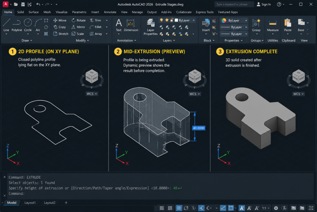
Standard EXTRUDE: Step-by-Step
- Prepare and validate the profile (closed polyline, circle, ellipse, or region).
- Type EXT (EXTRUDE) and press Enter.
- Select the profile. Press Enter.
- Type the extrusion height (depth) value and press Enter. Positive value extrudes in the positive Z direction of the current UCS; negative extrudes in the negative Z direction.
- The 3D solid appears. Inspect in isometric view.
EXTRUDE with Taper Angle
A taper angle makes the profile shrink or expand as it extrudes, creating a draft angle. Essential for injection moulded parts, castings, and components that need release angles.
- Type EXT, select profile, press Enter.
- Type T (Taper angle) and press Enter.
- Enter the taper angle in degrees. Positive tapers inward (profile shrinks toward the top), negative tapers outward.
- Enter the extrusion height. The solid tapers along its length.
EXTRUDE Along a Path
Instead of extruding perpendicular to the profile plane, EXTRUDE with the Path option follows a drawn curve:
- Draw the path (a line, arc, polyline, or spline) in the drawing.
- Type EXT, select the profile, press Enter.
- Type P (Path) and press Enter.
- Click the path object. The profile extrudes along the full length of the path.
REVOLVE: Profiles That Rotate Around an Axis
REVOLVE creates a 3D solid by rotating a profile around a defined axis. Use it for any rotationally symmetric component: shafts, bolts, cylinders, cones, flanges, bottles, and turned parts.
Creating the Correct Profile for REVOLVE
The profile for REVOLVE is the half-section cross-section: draw only the right half of the outline (from the centre axis outward). The profile does not need to be closed if it lies entirely on one side of the intended rotation axis — AutoCAD will close the revolution automatically. However, a closed half-profile produces more predictable results.
Full Step-by-Step: REVOLVE
- Draw the half-section profile as a closed polyline or as connected lines/arcs.
- Optionally draw an axis line along the centre of revolution, or note which edge of the profile will be the axis.
- Type REV (REVOLVE) and press Enter.
- Select the profile. Press Enter.
- At Specify axis start point: click the first point of the revolution axis.
- Click the second axis point, or type X, Y, or Z to revolve around the corresponding world axis.
- Enter the angle of revolution. Type 360 for a complete solid, or a partial angle for a sector.
LOFT: Multiple Profiles Blended into One Solid
LOFT creates a 3D solid that transitions smoothly between two or more cross-section profiles. Each profile defines the shape of the solid at that cross-sectional location, and LOFT blends between them.
Setting Up Profiles for LOFT
All profiles used in LOFT must be either all closed (to produce a solid) or all open (to produce a surface). You cannot mix closed and open profiles in a single LOFT operation. Each profile must lie on its own plane and the planes should generally be parallel for predictable results (though they do not have to be).
Full Step-by-Step: LOFT
- Draw at least two cross-section profiles at different positions along the intended axis of the solid.
- Type LOFT and press Enter.
- Select the profiles in order from one end to the other. Selecting out of sequence produces twisted results. Press Enter when all profiles are selected.
- At the Loft Options prompt, press Enter for Cross-sections only (the default, which produces the smoothest blend).
- In the Loft Settings dialogue, choose Smooth Fit for organic blends, Ruled for linear face transitions, or Normal to start and end sections for blends that are perpendicular to the end profiles.
- Click OK. The lofted solid appears.
SWEEP: Profiles Along a Curved or Custom Path
SWEEP extrudes a cross-section profile along any defined path object: a line, arc, circle, polyline, ellipse, or spline. Unlike EXTRUDE (which always goes perpendicular), SWEEP follows the geometry of the path exactly, making it ideal for curved extrusions such as pipe bends, architectural mouldings, and spiral springs.
Profile and Path Placement for SWEEP
The profile does not need to be drawn at the start of the path, but it must lie on a plane perpendicular to the path at the start point. AutoCAD automatically relocates the profile to the start of the path when SWEEP is run. If the profile and path are on the same plane, SWEEP handles the orientation automatically.
Full Step-by-Step: SWEEP
- Draw the closed 2D cross-section profile (the shape that will be swept).
- Draw the path the profile will follow (line, arc, polyline, or spline).
- Type SWEEP and press Enter.
- Select the profile. Press Enter.
- Select the path object. AutoCAD sweeps the profile along the full path length, creating the 3D solid.
Handling Nested Profiles and Profiles with Islands (Holes)
Many mechanical components have profiles with holes or internal cutouts — a plate with mounting holes, a hollow tube cross-section, or a washer outline. These are called profiles with islands. AutoCAD handles them differently depending on whether you use the direct EXTRUDE approach or a REGION Boolean approach.
Method A: EXTRUDE Then SUBTRACT (Most Reliable)
The most straightforward and reliable method for profiles with holes:
- Extrude the outer profile as normal to create the solid body.
- Create separate solid cutters for each hole (cylinders for round holes, boxes for rectangular pockets). Position them at the correct locations.
- Use SUBTRACT to cut the cutter solids from the body solid.
Method B: REGION Boolean Operations Before Extruding
If you prefer to define the complete profile including holes before extruding, use REGION Boolean operations:
- Create a REGION from the outer boundary.
- Create separate REGIONs from each hole or cutout boundary.
- Type SU (SUBTRACT), select the outer region as the body, press Enter, then select all inner regions as cutters, press Enter.
- The result is a single region with holes already cut into it.
- Extrude this compound region. The extruded solid will have holes running through it.
| Which Method Is Better? Method A (EXTRUDE then SUBTRACT) is simpler and less prone to errors. Method B (REGION Boolean then EXTRUDE) is useful when you want to verify the 2D profile visually before extruding, or when the profile shape changes because of the holes (e.g., thin walls between adjacent holes require careful profile validation before extruding). |
Converting Existing Objects to Solids (CONVTOSOLID and THICKEN)
Sometimes you have existing AutoCAD objects that are not profiles but need to become solids. Two commands handle specific conversion scenarios:
CONVTOSOLID: Converting Meshes and Polyfaces
CONVTOSOLID converts AutoCAD mesh objects, polyface meshes, and zero-width closed polylines with thickness into 3D solids. Type CONVTOSOLID, select the object, press Enter. If the conversion is possible, AutoCAD creates a solid from the selected object. This is useful when working with imported mesh geometry from older files or from other software.
THICKEN: Converting Surfaces to Solids
THICKEN converts a 2D surface object (created by EXTRUDE or LOFT on an open profile) into a 3D solid by adding thickness. Type THICKEN, select the surface, press Enter, enter the thickness value. AutoCAD creates a solid of the specified thickness from the surface. This is particularly useful when you have created a complex surface shape using LOFT or SWEEP on open profiles and then need to give it physical thickness for manufacturing purposes.
Profile Troubleshooting: Why Won’t AutoCAD Extrude My Profile?
This section is the one that most AutoCAD tutorials skip entirely and that users search for most desperately. Here is a complete reference for every common profile-to-solid failure mode, what causes it, and exactly how to fix it.
| Error or Symptom | Root Cause | Diagnosis Method | Fix |
| EXTRUDE creates a surface instead of a solid | Profile is an open polyline or open spline rather than a closed boundary | Click profile. Type PEDIT, check if ‘Close’ option appears (means it is open) | Type PEDIT > Close to close the polyline, or use REGION to convert the boundary to a closed region |
| EXTRUDE gives error: ‘Object is not a closed loop’ | Profile consists of separate line and arc segments that are not joined into a single object | Click profile. If individual segments highlight separately, they are not joined | Use PEDIT > Multiple > Join to weld all segments into one polyline. Set fuzz distance to 0.001 if needed. |
| Profile appears closed visually but EXTRUDE still creates a surface | Tiny gap between two segment endpoints invisible at normal zoom | Zoom in extreme (type Z, E for extents then zoom in 10x) to the endpoint area and check for gaps with endpoint OSNAP | Move one endpoint to exactly meet the other using MOVE and endpoint OSNAP, or use PEDIT Join with a small fuzz distance |
| EXTRUDE fails with ‘Object is not a region or 2D curve’ | Profile is a 3D object or has Z-coordinate variation across its points | Type LIST on the profile. Check if any vertex Z values differ from the others | Use FLATTEN command (or set all vertices to Z=0 manually with PEDIT) to make the profile truly planar |
| LOFT creates a twisted solid between profiles | Profiles were selected out of sequential order | Inspect the solid. Twisting indicates profiles were joined in the wrong order | Undo and repeat LOFT. Select profiles strictly from one end to the other in order |
| REVOLVE creates a surface with a gap rather than a closed solid | Profile crosses the revolution axis or the axis is positioned inside the profile | Visually check profile position relative to axis line | Move the profile so its edge aligns with but does not cross the intended axis, or use an axis defined by two points that lies exactly along the profile edge |
| SWEEP produces an unexpected shape or the profile appears tilted | Profile is not perpendicular to the path at the sweep start point | Check the angle between the profile plane and the path start tangent in isometric view | Rotate the profile 90 degrees to align its plane perpendicular to the path direction before sweeping |
| BOUNDARY detects wrong area or does not close | Background geometry has overlapping or unclosed segments near the picked point | Use ZOOM to inspect the area closely. Look for stray lines or unclosed segments nearby | Clean up the background geometry. Delete stray lines and close any open segments before running BOUNDARY again |
Frequently Asked Questions (FAQ)
How do you make a 3D solid from a profile outline in AutoCAD?
To make a 3D solid from a profile outline in AutoCAD: (1) Ensure the profile is a single closed object — a closed polyline, circle, ellipse, or REGION. Use PEDIT > Join to combine separate lines and arcs, or BOUNDARY to auto-detect a closed boundary. (2) Confirm the profile is on the correct UCS plane. (3) Type EXT (EXTRUDE), select the profile, press Enter, and type the extrusion depth. For rotationally symmetric parts, use REVOLVE; for profiles following a curve, use SWEEP; for profiles that blend between shapes, use LOFT.
Why does AutoCAD create a surface instead of a solid when I use EXTRUDE?
AutoCAD creates a surface instead of a solid when the profile passed to EXTRUDE is an open polyline, arc, or spline rather than a closed boundary. EXTRUDE requires a completely closed profile to produce a solid. To fix it: type PEDIT, select the polyline, choose Close to close it if its start and end points are the same location but not explicitly connected. If the profile consists of separate segments with gaps between them, use PEDIT > Join with a small fuzz distance, or use REGION to convert the entire closed boundary to a region object.
What is the PEDIT Join command in AutoCAD?
PEDIT Join (Polyline Edit Join) is an AutoCAD command that converts a collection of separate connected line and arc segments into a single unified polyline. It is the primary method for preparing profile outlines for 3D extrusion. To use it: type PEDIT, type M for Multiple mode, select all the segments forming the profile boundary, press Enter, type Y to convert to polylines, type J (Join), set a fuzz distance (0 for clean drawings, a small value like 0.001 for drawings with tiny gaps), and press Enter. The result is a single closed polyline ready for EXTRUDE.
What is the difference between REGION and a closed polyline in AutoCAD?
Both are valid profile types for 3D solid creation commands, but they have different properties. A closed polyline is a 1D curve that traces a closed boundary. A REGION is a flat 2D planar object that has area and is treated as a filled surface. REGIONs support Boolean operations (SUBTRACT, UNION, INTERSECT) between each other, allowing complex profiles with holes to be defined before extruding. Closed polylines cannot be Booleans-operated before extrusion. For simple solid profiles, either works. For complex profiles with internal cutouts, REGION is often more efficient.
What is the BOUNDARY command in AutoCAD?
The BOUNDARY command (BO) in AutoCAD automatically detects and traces the boundary of any closed area in the drawing. You click inside the area and AutoCAD creates a new polyline or region object following the exact perimeter of that enclosed space. The original geometry is preserved and the new profile object is created on top of it. BOUNDARY is faster than PEDIT Join for complex areas defined by intersecting geometry, and it preserves all the original drawing lines and arcs unchanged.
How do I extrude a profile with holes in AutoCAD?
To extrude a profile with holes in AutoCAD, use one of two methods. Method 1 (simpler): extrude the outer profile to create the body solid, then create cylinder or box solids at the hole positions and use SUBTRACT to cut them from the body. Method 2 (pre-extrusion): create a REGION from the outer boundary, create REGIONs from each hole boundary, use SUBTRACT to subtract the hole regions from the outer region, then EXTRUDE the resulting compound region. The extruded solid will have the holes built in.
Why does AutoCAD extrude in the wrong direction?
AutoCAD extrudes perpendicular to the current UCS XY plane in the positive Z direction by default. If the extrusion goes in the wrong direction, either the UCS is oriented incorrectly for the operation, or you entered a positive depth when a negative value was needed (or vice versa). To fix: type UCS > W to reset to World UCS, verify the UCS icon X and Y directions in your viewport match your expected orientation, then re-run EXTRUDE. Enter a negative depth value to extrude in the opposite direction from default.
Conclusion
Making a 3D solid from a profile outline in AutoCAD is fundamentally a two-stage process: get the profile right, then choose the right creation command. Of those two stages, getting the profile right is the one that determines whether the operation succeeds or fails, and it is the stage that most tutorials skip entirely.
A correctly prepared profile — a single closed polyline, a circle, an ellipse, or a REGION — will extrude, revolve, loft, or sweep reliably and produce exactly the solid you intended. A poorly prepared profile will fail silently, produce a surface instead of a solid, or extrude in the wrong direction. The four preparation methods in this guide (POLYLINE from scratch, PEDIT Join, REGION, and BOUNDARY) cover every scenario from clean new drawings to complex imported geometry.
The troubleshooting table at the end of this guide covers every common failure mode. Bookmark it and use it as a reference whenever a profile refuses to extrude as expected. In most cases the diagnosis takes less than a minute and the fix takes less than two.
Continue learning AutoCAD 3D: read How to Create a 3D Model from 2D Views for the complete orthographic-to-solid workflow, or return to the complete AutoCAD Tutorials for Beginners and Professionals guide.