Tag: AutoCAD 3D Modelling

  • Dynamic Block Lookup Tables in AutoCAD Explained (2026)

    Dynamic Block Lookup Tables in AutoCAD Explained (2026)

    AutoCAD’s dynamic blocks are one of the most powerful productivity tools in the software, allowing a single block definition to represent dozens or even hundreds of variations through parameters and actions. But even among experienced AutoCAD users who are comfortable with stretch, scale, and visibility parameters, lookup tables remain one of the least understood and most underused features of the dynamic block system.

    A lookup table takes a dynamic block to a completely different level of usability. Instead of users having to manipulate grips, type specific values, or know the exact dimensions of a component they are placing, a lookup table presents them with a simple dropdown list: select ‘M8 Bolt’, or ‘Type A Door’, or ‘600mm Wide Desk’, and the block automatically sets all associated parameters to the correct values simultaneously. One selection drives everything.

    This guide explains AutoCAD dynamic block lookup tables from the ground up. It covers what they are and why they are useful, the conceptual building blocks (lookup parameters versus lookup actions), how to create a single-parameter lookup table step by step, how to build a multi-parameter lookup that drives multiple block properties from one dropdown, the Allow Reverse Lookup setting that confuses almost every user who first encounters it, how to extract lookup data for bills of materials and parts lists, and a full troubleshooting reference for every common problem.

    Quick Answer:  A dynamic block lookup table in AutoCAD is a table inside a dynamic block definition that maps a named entry (e.g. ‘M10 Bolt x 50mm’) to a specific set of parameter values (e.g. Diameter = 10, Length = 50, Head Height = 6.4). When a user selects that entry from the block’s grip dropdown, AutoCAD automatically applies all associated parameter values simultaneously. It is created in the Block Editor using a Lookup Parameter and a Lookup Action.

    What Is a Dynamic Block Lookup Table and Why Use One?

    In the context of AutoCAD dynamic blocks, a lookup table is a structured internal table that associates named text entries (the list items a user sees in the dropdown) with corresponding values for one or more block parameters. It is the mechanism that converts a block from something a user manipulates by dragging grips to something a user selects from a predefined list.

    Think of a lookup table as the dynamic block equivalent of a product catalogue. A block representing a structural steel section might have a lookup table containing every standard section size: UC203x203x60, UC203x203x71, UC254x254x89, and so on. The user selects the section from the dropdown, and the block instantly updates to the correct flange width, depth, and web thickness , all values set simultaneously from a single selection.

    The Problem Lookup Tables Solve

    Without a lookup table, a dynamic block user faces one of two sub-optimal workflows. Either they drag grips and hope they snap to the correct values, or they type exact values into the Properties palette manually. Both approaches are slow and error-prone, especially when blocks represent components with manufacturer-standard dimensions that must be exact.

    A lookup table eliminates both problems. It constrains the block to only valid, predefined configurations and presents those configurations in a human-readable named list. The user never needs to know the exact numeric values , they just pick the configuration they need.

    Read related article on How to Sort Tables in AutoCAD

    When to Use a Lookup Table vs Other Dynamic Block Features

    SituationBest ApproachWhy
    Block has 2-3 continuous size variations that users need to set to any valueLinear/scale parameter with value sets or incrementLookup table adds unnecessary complexity for simple continuous size changes
    Block has a fixed catalogue of named configurations (e.g. standard hardware, furniture sizes)Lookup tableBest: presents named options, ensures only valid configurations are used, drives multiple parameters at once
    Block needs to show/hide different geometry based on a selectionVisibility statesVisibility states are specifically designed for geometry show/hide. Lookup tables control parameter values, not direct visibility.
    Block has named configurations AND geometry differences (e.g. door type with different swing geometry)Lookup table + Visibility states combinedUse lookup for dimensions, visibility states for geometry changes, link them via the lookup table
    Block configuration depends on 3+ parameters that all change togetherLookup table with multiple property columnsOnly a lookup table can drive multiple parameters simultaneously from one selection

    Lookup Parameter vs Lookup Action: Understanding the Two-Part System

    The single most common source of confusion for users learning dynamic block lookup tables is not understanding the relationship between the Lookup Parameter and the Lookup Action. These are two separate objects placed in the Block Editor, and both are required. Neither works without the other. Understanding what each one does makes the entire workflow logical.

    ObjectWhat It IsWhat It DoesVisible to User?
    Lookup ParameterA parameter added from the Parameters tab of the Block Authoring PaletteProvides the grip (dropdown handle) that users see and interact with when the block is inserted. It holds the currently selected lookup value name (e.g. ‘M10 Bolt x 50mm’). The parameter itself has no values until connected to a Lookup Action.Yes , the grip appears as a small arrow or diamond on the inserted block
    Lookup ActionAn action added from the Actions tab of the Block Authoring PaletteContains the actual lookup table: the rows of data mapping named entries to parameter values. The Lookup Action reads the current value of the Lookup Parameter and sets all other block parameters to the corresponding row values in its table.No , the action is invisible in the drawing. It is a background engine.

    The workflow is therefore always in this order: (1) Set up the block parameters that will be controlled by the lookup table (length, width, visibility state, etc.). (2) Place the Lookup Parameter in the Block Editor. (3) Place the Lookup Action and attach it to the Lookup Parameter. (4) Open the Lookup Table inside the Lookup Action and populate the rows with named entries and corresponding parameter values.

    The Most Common Mistake:  Placing a Lookup Action without first setting up the parameters it will control. A Lookup Action is only useful if there are already named parameters in the block (linear parameters, visibility states, rotation parameters, etc.) whose values the action will set. If you open the Lookup Table and the ‘Add Properties’ button produces an empty list, it means no controllable parameters are available , go back and add the required parameters first.

    Prerequisites: What Your Dynamic Block Needs Before Adding a Lookup Table

    Before adding a lookup table, the dynamic block must already have the parameters whose values the lookup table will control. Here is what must be in place before entering the Block Editor to add lookup functionality:

    • At least one controlling parameter: A Linear parameter (for size), Rotation parameter (for angle), Visibility parameter (for geometry variants), or any other named parameter that can hold a value. The lookup table will set the values of these parameters.
    • Parameters must be named: Each parameter should have a clear, descriptive name (e.g. ‘Width’, ‘Height’, ‘Leg Style’) so you can identify it when adding columns to the lookup table.
    • For multi-parameter lookups: All parameters you want the lookup to control must be present in the block before adding the Lookup Action. You cannot add parameters to the lookup table that do not yet exist in the block.
    • The block should be tested without the lookup: Verify that the parameters and their associated actions (Stretch, Scale, Visibility) work correctly by testing the block with grip manipulation before adding the lookup layer on top.

    Step-by-Step: Creating a Single-Parameter Lookup Table

    This walkthrough creates a lookup table for a bolt block that already has a Linear parameter named ‘Length’ controlling the bolt body geometry via a Stretch action. The lookup table will let users select bolt lengths from a named list (M8x20, M8x25, M8x30, M8x40) rather than dragging a grip.

    Step 1: Open the Block Editor

    1. Double-click the inserted block to open it, or type BEDIT and press Enter, then select the block definition from the list.
    2. The Block Editor opens. The Block Authoring Palettes panel should be visible on the left. If not, go to Block Editor tab > Manage panel > Authoring Palettes to show it.

    Step 2: Place the Lookup Parameter

    1. In the Block Authoring Palettes, click the Parameters tab.
    2. Scroll down to find Lookup in the parameter list and click it.
    3. AutoCAD prompts: Specify parameter location:. Click a location on the block where the grip (dropdown handle) will appear when the block is inserted. A good position is just to the side of the block, away from functional grips.
    4. AutoCAD prompts for the number of grips: accept the default of 1 and press Enter.
    5. A Lookup grip appears at the specified location, labelled ‘Lookup’ by default. In the Properties palette (Ctrl + 1), rename the parameter to something descriptive, such as ‘Bolt Size’ or ‘Select Size’. This name appears as the label next to the grip when the block is in use.
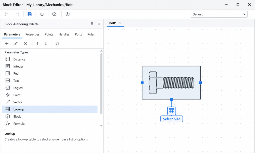
    AutoCAD Block Editor showing Lookup Parameter being placed in the Block Authoring Palette for a bolt dynamic block lookup table

    Step 3: Place the Lookup Action

    1. In the Block Authoring Palettes, click the Actions tab.
    2. Click Lookup in the action list.
    3. AutoCAD prompts: Select parameter:. Click the Lookup Parameter you placed in Step 2 (the grip labelled ‘Bolt Size’).
    4. The Property Lookup Table dialogue opens automatically. This is the actual lookup table where you define the rows of data.

    Step 4: Build the Lookup Table

    1. In the Property Lookup Table dialogue, click Add Properties.
    2. A list of the block’s controllable parameters appears. Select ‘Length’ (the parameter you want to control). Click OK. A ‘Length’ column appears in the table.
    3. The table now has two columns: Lookup Name (the dropdown text the user will see) and Length (the parameter value AutoCAD will set).
    4. Click in the first empty row of the Lookup Name column and type the first entry name (e.g. ‘M8 x 20mm’). Press Tab to move to the Length column and type the corresponding value: 20.
    5. Press Enter or click the next row. Continue adding rows for each size:
    Lookup Name (User Sees)Length (Parameter Value)
    M8 x 20mm20
    M8 x 25mm25
    M8 x 30mm30
    M8 x 40mm40
    M8 x 50mm50
    1. In the Lookup name column at the bottom of the table (the last row with a dropdown), set the Input Properties setting to Allow Reverse Lookup. This setting is critical , see the next section for a full explanation.
    2. Click OK to close the Property Lookup Table dialogue.
    3. Go to Block Editor tab > Close panel > Save Block and then Close Block Editor.

    Step 5: Test the Lookup Table

    1. Insert or select the block in the drawing.
    2. Click the Lookup grip (the dropdown handle you placed). A dropdown list appears with the names you entered: M8 x 20mm, M8 x 25mm, M8 x 30mm, etc.
    3. Select any entry. The block’s Length parameter updates to the corresponding value and the block geometry stretches to match.
    Verification Step:  After testing, open the Properties palette (Ctrl + 1) with the block selected. The palette should show the Lookup Parameter name and its current value. Check that the Length parameter value matches the number you entered in the lookup table for the selected entry. If it does not match, revisit the Lookup Action and verify the correct parameter column is mapped to the correct value.
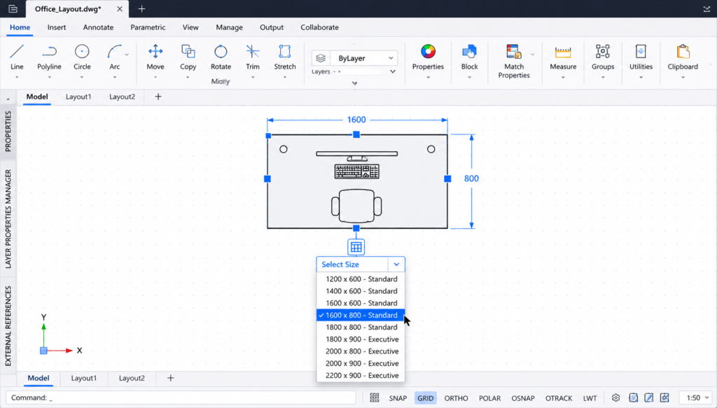
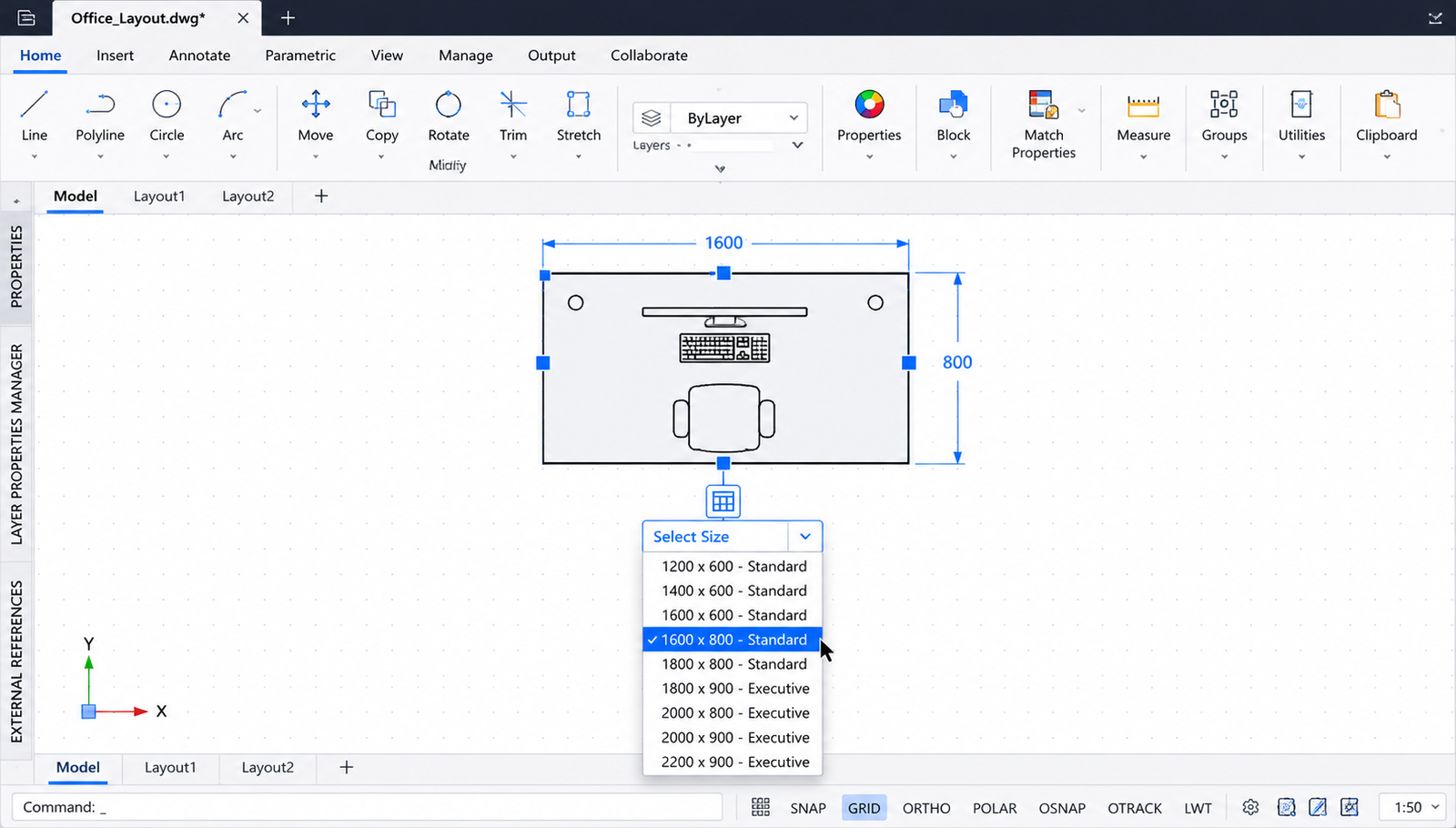
    AutoCAD dynamic block with lookup table dropdown showing named desk configurations including L-shape options available for selection

    More guide on How to Use DXF Files in AutoCAD

    Step-by-Step: Creating a Multi-Parameter Lookup Table

    The real power of AutoCAD dynamic block lookup tables becomes apparent when driving multiple parameters simultaneously from a single dropdown selection. This worked example creates a lookup table for a desk block with three parameters: Width (linear), Depth (linear), and Style (visibility state for standard vs L-shaped desk geometry).

    Block Setup Before Adding the Lookup

    This block already has:

    • Linear Parameter ‘Width’ , controlling the desk width with a Stretch action
    • Linear Parameter ‘Depth’ , controlling the desk depth with a Stretch action
    • Visibility Parameter ‘Desk Style’ , with two visibility states: ‘Standard’ (rectangular desk) and ‘L-Shape’ (L-shaped desk geometry)

    Adding the Multi-Parameter Lookup

    1. Open the Block Editor (BEDIT) for the desk block.
    2. Add a Lookup Parameter from the Parameters tab, placed at a convenient grip location. Name it ‘Select Desk’ in the Properties palette.
    3. Add a Lookup Action from the Actions tab, clicking the Lookup Parameter you just placed.
    4. The Property Lookup Table dialogue opens. Click Add Properties.
    5. Select Width, Depth, and Desk Style from the parameter list. All three are now columns in the table.
    6. Fill in the table with all required desk configurations:
    Lookup NameWidthDepthDesk Style
    600 x 600 Standard600600Standard
    800 x 600 Standard800600Standard
    1000 x 600 Standard1000600Standard
    1200 x 600 Standard1200600Standard
    1200 x 800 Standard1200800Standard
    1400 x 800 Standard1400800Standard
    1200 x 1200 L-Shape12001200L-Shape
    1400 x 1400 L-Shape14001400L-Shape
    1600 x 1600 L-Shape16001600L-Shape
    1. Set the Input Properties for the last table row to Allow Reverse Lookup.
    2. Click OK, save the block, and close the Block Editor.
    3. Test the block: clicking the ‘Select Desk’ grip should show a dropdown of all nine configurations. Selecting ‘1200 x 1200 L-Shape’ should simultaneously set Width to 1200, Depth to 1200, and switch the visibility state to L-Shape geometry.
    Multi-Parameter Power:  Notice that one selection from the dropdown drove three separate parameters at the same time. Without a lookup table, a user would need to set Width, Depth, and Desk Style separately , three operations instead of one. As the number of parameters and configurations grows, the time savings from a lookup table multiply significantly.

    Allow Reverse Lookup vs Read Only: The Most Misunderstood Setting

    The Input Properties setting at the bottom of the lookup table (the dropdown in the final row of the table) is one of the most confusing aspects of dynamic block lookup tables. Almost every user who first builds a lookup table wonders why it is not working , and the answer is almost always this setting.
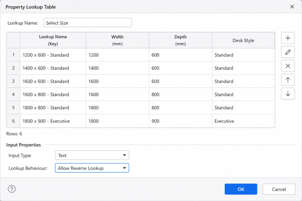
    AutoCAD Property Lookup Table dialogue showing multi-parameter lookup table with Allow Reverse Lookup setting selected
    SettingWhat It DoesVisible in Dropdown?When to Use It
    Allow Reverse LookupAllows the lookup table to work in both directions: the user can select from the dropdown (lookup name → parameter values) AND AutoCAD can determine the current lookup name by reading the current parameter values. The dropdown list of named entries IS visible to the user.YES , user sees the named entries and can select from themAlmost always. This is the standard setting for any lookup table where users need to select from a dropdown list. If the lookup dropdown appears empty or shows no entries, this setting is almost certainly missing.
    Read OnlyThe lookup table only works in one direction: parameter values → lookup name. The current lookup name updates to reflect parameter values set by other means (grip manipulation), but the user CANNOT select from the dropdown , it is read-only. Named entries are NOT visible for selection.NO , no selectable entries in the dropdownOnly in rare specialist cases where the lookup name is used purely as a display label that tracks parameter values without allowing user selection. Not appropriate for standard dropdown-selection workflows.
    The Single Most Common Lookup Table Problem:  You build a lookup table, close the Block Editor, insert the block, click the grip, and the dropdown appears but shows no entries , or shows ‘Custom’ and nothing else. The cause is almost always Input Properties set to ‘Read Only’ instead of ‘Allow Reverse Lookup’. Open the Block Editor, double-click the Lookup Action, open the Property Lookup Table, and change the Input Properties dropdown at the bottom of the table from Read Only to Allow Reverse Lookup. Save and test. This fixes the problem in virtually every case.

    The Custom Entry: Why It Appears and What It Means

    When you insert a dynamic block with a lookup table and click the Lookup grip, you may see ‘Custom’ as an entry in the dropdown list, sometimes with a checkmark beside it. This confuses almost every user who encounters it for the first time.

    What ‘Custom’ Means

    ‘Custom’ is AutoCAD’s way of telling you that the block’s current parameter values do not match any named entry in the lookup table. It appears as a checkmarked entry when the block is in a state that falls outside the defined catalogue of configurations.

    This most commonly happens in three situations: when the block has just been inserted before any lookup selection has been made (the block is in its default state which may not match any lookup entry); when a user has manually set parameter values by dragging grips or typing in the Properties palette to a value not listed in the lookup table; or when the block has been copied from a version with different parameter defaults.

    Should You Worry About ‘Custom’?

    Not necessarily. ‘Custom’ is informational , it tells the user the block is currently in a non-catalogued state. To remove ‘Custom’ from the dropdown entirely: ensure that the block’s default parameter values (set in the Block Editor) match one of the entries in the lookup table. If the default Width is 800 and the lookup table has an ‘800 x 600 Standard’ entry with Width = 800, the block will start in that named state and ‘Custom’ will not appear.

    Real-World Use Cases for Dynamic Block Lookup Tables

    The following examples represent the most common and valuable applications of dynamic block lookup tables across engineering, architecture, and design disciplines.

    IndustryBlock ExampleLookup Table EntriesParameters Controlled
    Mechanical EngineeringStandard bolt or fastener blockM6x20, M6x25, M8x20, M8x25, M8x30, M10x30, M10x40…Shaft diameter, length, head height, thread length , all from one selection
    Mechanical EngineeringStructural steel section blockUC203x203x46, UC203x203x60, UC254x254x73, UB254x102x25…Section depth, flange width, web thickness, mass/metre label visibility
    ArchitectureDoor blockSingle 762, Single 838, Single 914, Double 1524, Double 1676…Door width, door height, single/double visibility state, swing direction
    ArchitectureWindow block600 Fixed, 900 Casement, 1200 Casement, 1800 Fixed…Opening width, frame depth, fixed/casement visibility state
    Electrical EngineeringElectrical cabinet / switchboard block200H x 400W, 400H x 400W, 600H x 600W, 800H x 600W…Overall height, overall width, number of circuit rows visibility
    Interior Design / FF&EOffice chair blockTask Chair, Executive Chair, Meeting Chair, Bar Stool…Seat height, back height, armrest visibility, star base/bar base visibility
    Civil EngineeringManhole block450 Dia, 600 Dia, 900 Dia, 1200 Dia, 1500 Dia…Chamber diameter, cover diameter, cover type visibility
    Manufacturing / WorkshopStandard channel section25x25x3, 40x40x5, 50x50x6, 75x50x6…Width, height, wall thickness , all simultaneously from standard size list

    Extracting Lookup Table Data for Bills of Materials and Parts Lists

    One of the most powerful and least-known capabilities of dynamic block lookup tables is that the lookup name value , the text that appears in the dropdown , can be extracted from the drawing as part of a Data Extraction, exactly like a block attribute. This allows a drawing containing multiple dynamic block instances to automatically generate a parts list, bill of materials, or schedule showing the lookup name for each block.

    How Lookup Data Appears in Data Extraction

    When you run DATAEXTRACTION on a drawing containing dynamic blocks with lookup tables, the lookup parameter name and its current value (the selected lookup name) appear in the property list on Page 3 of the wizard (Select Properties). Select the lookup parameter property to include it in the extraction, and the generated table will show the selected lookup entry for each block instance.

    Step-by-Step: Extracting Lookup Table Data

    1. Ensure all dynamic blocks in the drawing have their lookup selections set correctly.
    2. Type DATAEXTRACTION and press Enter.
    3. On Page 2 (Define Data Source), select Drawings/Sheet Set and check that the current drawing is included.
    4. On Page 3 (Select Objects), select the block definition you want to extract data from. Tick Display all object types if the block does not appear in the initial list.
    5. On Page 3 (Select Properties), scroll through the property list to find the Lookup Parameter name (e.g. ‘Bolt Size’, ‘Select Desk’). Tick it along with any other block properties or attributes you want in the extraction.
    6. Continue through the wizard, set up the output table format, and insert the extracted table. The resulting table shows each block instance with its selected lookup name.
    Practical Application:  A structural engineer places 47 instances of a steel section dynamic block throughout a drawing, selecting different section sizes from the lookup dropdown for each. Running DATAEXTRACTION generates a full steel schedule automatically , showing section designation, quantity, and total length for each section size. Updating any block’s selection and refreshing the Data Extraction table updates the schedule instantly.

    Editing and Updating an Existing Lookup Table

    Adding new entries, changing values, or removing rows from an existing lookup table is straightforward. All changes happen inside the Block Editor.

    1. Type BEDIT and select the block definition to edit.
    2. In the Block Editor, locate the Lookup Action (it appears as a yellow lightning bolt action icon near the Lookup grip). Double-click the Lookup Action icon.
    3. The Property Lookup Table dialogue opens showing the existing table.
    4. To add a new row: click in an empty row at the bottom of the table and type the new Lookup Name and parameter values.
    5. To edit an existing value: click the cell and type the new value.
    6. To delete a row: select the row and press Delete.
    7. To add a new parameter column: click Add Properties, select the new parameter from the list, and fill in values for each row.
    8. Click OK to close the dialogue. Save the block and close the Block Editor.
    9. All instances of the block in the drawing update immediately to reflect the revised lookup table.

    Lookup Tables vs Visibility States: Choosing the Right Approach

    Both lookup tables and visibility states allow users to switch between named configurations of a dynamic block from a dropdown. Understanding the distinction between them prevents the common mistake of using one when the other would be more appropriate.

    FeatureLookup TableVisibility States
    Primary purposeControl numeric parameter values (dimensions, angles) and optionally visibility states from one dropdownShow or hide specific geometry (objects) within the block based on the selected state
    User interactionLookup Parameter grip , presents a dropdown of named entriesVisibility Parameter grip , presents a dropdown of named states
    What changes on selectionParameter values (Width, Height, Angle, etc.) and optionally Visibility stateWhich objects are visible/hidden within the block
    Can control dimensions?Yes , primary purposeNo , dimensions must be changed separately or via a lookup table linked to the visibility state
    Can show/hide geometry?Yes , if a Visibility Parameter is included as a column in the lookup tableYes , primary purpose
    Best forCatalogue-based selection of standard sizes; anything where exact numeric values must be enforcedBlocks with fundamentally different geometric forms (e.g. different valve types, door swings, electrical symbols)
    Can be used together?Yes , include a Visibility parameter as one column in the lookup table to drive both dimensions and geometry simultaneouslyYes , use alongside a lookup table for complete control over both geometry and dimensions

    Dynamic Block Lookup Table Troubleshooting

    ProblemRoot CauseFix
    Lookup dropdown appears but shows no named entries (empty list)Input Properties is set to ‘Read Only’ instead of ‘Allow Reverse Lookup’Open BEDIT, double-click the Lookup Action, open the Property Lookup Table, change the Input Properties dropdown at the bottom from Read Only to Allow Reverse Lookup. Save and test.
    Lookup dropdown only shows ‘Custom’ and nothing elseSame as above , Read Only setting prevents forward lookup. Alternatively, lookup table has no rows filled in.Change to Allow Reverse Lookup. Also verify the table has populated rows , scroll through the Property Lookup Table to confirm entries exist.
    ‘Add Properties’ shows an empty list when building the lookup tableNo controllable parameters exist in the block yet. Lookup Action was added before the block parameters it should control.Cancel, exit the Block Editor, and set up the required parameters (Linear, Visibility, Rotation, etc.) first. Then re-enter the Block Editor and add the Lookup Parameter and Action.
    Selecting a lookup entry does not change the block geometryThe parameter controlled by the lookup table has no associated action (Stretch, Scale, etc.) driving the geometryVerify that the parameters listed in the lookup table columns have associated actions. A parameter with no action holds a value but changes nothing visually.
    Lookup grip does not appear on the inserted blockLookup Parameter was placed inside the block but the block definition was not saved before closing the Block EditorRe-open BEDIT, verify the Lookup Parameter is present, and use Save Block (not just Close) before closing the Block Editor.
    All instances of the block show the same lookup selection regardless of what was chosenBlock was placed as a block reference that was then copied , all copies share the same dynamic block state if the block was not properly inserted as independent instancesUse INSERT to place each block independently, or use the Properties palette to change the lookup value on each selected instance individually.
    Lookup table values appear correct but Data Extraction shows wrong or missing lookup namesData Extraction property filter does not include the Lookup Parameter property, or the lookup name is being extracted as a block attribute rather than a dynamic propertyRe-run DATAEXTRACTION. On Page 3 (Select Properties), scroll carefully to find the Lookup Parameter name in the property list and tick it specifically.
    Lookup entry names are correct but the block geometry looks wrong after selectionParameter values in the lookup table rows do not match the values expected by the block’s actions, or the parameter was renamed after the lookup table was set upOpen BEDIT, double-click the Lookup Action, verify each row’s parameter values are correct. Check that parameter names in the table match the current parameter names in the block.

    Frequently Asked Questions (FAQ)

    What is a dynamic block lookup table in AutoCAD?

    A dynamic block lookup table in AutoCAD is an internal data table within a dynamic block definition that maps named text entries to specific parameter values. When a user selects an entry from the block’s dropdown grip (such as ‘M10 Bolt x 50mm’), the lookup table automatically sets all associated block parameters (diameter, length, head height) to the corresponding values. It is created in the Block Editor using a Lookup Parameter (which provides the dropdown grip) and a Lookup Action (which contains the table data).

    How do I create a lookup table in an AutoCAD dynamic block?

    To create a lookup table in an AutoCAD dynamic block: (1) Open the block in the Block Editor (BEDIT). (2) Add the parameters you want to control (Linear, Visibility, etc.) if not already present. (3) Place a Lookup Parameter from the Parameters tab of the Block Authoring Palette. (4) Place a Lookup Action from the Actions tab, clicking the Lookup Parameter. (5) In the Property Lookup Table dialogue, click Add Properties, select the parameters to control, and fill in named entries and their corresponding parameter values. (6) Set Input Properties to Allow Reverse Lookup. (7) Click OK, save the block, and close the Block Editor.

    Why does my AutoCAD dynamic block lookup dropdown show no entries?

    If the lookup dropdown shows no entries (or only shows ‘Custom’), the most common cause is that the Input Properties setting in the lookup table is set to ‘Read Only’ instead of ‘Allow Reverse Lookup’. To fix: open the Block Editor (BEDIT), double-click the Lookup Action icon, open the Property Lookup Table, and change the Input Properties dropdown at the bottom from Read Only to Allow Reverse Lookup. Save the block and test. This resolves the empty dropdown in the vast majority of cases.

    What is the difference between Allow Reverse Lookup and Read Only in AutoCAD?

    In an AutoCAD dynamic block lookup table, Allow Reverse Lookup makes the named entries visible in the dropdown list so the user can select them. The block reads the selection and sets parameter values accordingly. Read Only makes the lookup table work only in the reverse direction: it displays the lookup name that corresponds to the current parameter values (set by other means), but the user cannot select entries from the dropdown. For standard dropdown-selection workflows, always use Allow Reverse Lookup.

    What does ‘Custom’ mean in an AutoCAD dynamic block lookup dropdown?

    ‘Custom’ appears in a dynamic block lookup dropdown when the block’s current parameter values do not match any named entry in the lookup table. It means the block is in a non-catalogued state , either its default values do not correspond to any lookup entry, or a user has manually set parameter values outside the predefined options. To prevent ‘Custom’ appearing on insertion, ensure the block’s default parameter values in the Block Editor match one of the rows in the lookup table.

    Can a dynamic block lookup table control multiple parameters at once?

    Yes. An AutoCAD dynamic block lookup table can control multiple parameters simultaneously from a single dropdown selection. In the Property Lookup Table dialogue, click Add Properties and select all the parameters you want the lookup to control. Each selected parameter becomes a column in the table. You then fill in values for each parameter in each row , one selection from the dropdown sets all column values at once. This is one of the most powerful features of the lookup table system.

    How do I extract lookup table data from dynamic blocks for a parts list?

    To extract lookup table data for a parts list: run the DATAEXTRACTION command and work through the wizard. On Page 3 (Select Properties), select the block definition and scroll through the property list to find the Lookup Parameter name (the descriptive name you gave the lookup parameter, e.g. ‘Bolt Size’ or ‘Select Desk’). Tick this property along with any block attributes and other properties needed for the parts list. Complete the wizard and insert the table. The table will show the selected lookup entry for each block instance in the drawing.

    Conclusion

    Dynamic block lookup tables are one of the most productivity-transforming features in AutoCAD’s block system. They take the power of dynamic blocks , already a significant step up from standard static blocks, and add a layer of usability and reliability that makes them suitable for professional production environments where accuracy and consistency are non-negotiable.

    Once you understand that the system has two parts (a Lookup Parameter for the grip, a Lookup Action for the data), that Allow Reverse Lookup is almost always the correct setting, and that any number of parameters can be driven simultaneously from a single dropdown, the rest of the workflow falls into place logically.

    The real returns come when lookup tables are combined with Data Extraction: a drawing full of properly configured dynamic blocks with lookup tables becomes a living document where the geometry and the parts list stay in perfect sync, updating automatically as design decisions change. That is the end state that makes the investment in building lookup table-equipped blocks worthwhile.

    Continue building your AutoCAD expertise: read How to Sort Tables in AutoCAD for working with the data you extract, or return to the complete AutoCAD Tutorials for Beginners and Professionals guide.
  • How to Make a 3D Solid from Profile Outlines in AutoCAD

    How to Make a 3D Solid from Profile Outlines in AutoCAD

    You have drawn a 2D outline in AutoCAD. Maybe it is the cross-section of a mechanical part. Maybe it is an architectural wall layout, a swept path profile, or the silhouette of a component from an engineering drawing. Now you need to turn that flat outline into a 3D solid with actual volume, mass, and surfaces. This is one of the most fundamental workflows in AutoCAD 3D modelling, and it is also one of the most commonly broken.

    The breaking point is almost always the same: the profile outline. AutoCAD’s solid creation commands — EXTRUDE, REVOLVE, LOFT, SWEEP — all have one non-negotiable requirement: the profile must be a closed, valid 2D boundary. A profile that looks closed visually is not always closed geometrically. Individual lines and arcs that appear to touch often have tiny gaps between their endpoints. Profiles drawn with separate line segments rather than a single polyline frequently fail silently, producing surfaces instead of solids or generating an error message that gives no useful guidance on how to fix it.

    This guide covers the complete workflow from profile outline to finished 3D solid: how to create profiles correctly from scratch, how to diagnose and fix problem profiles that refuse to extrude, which command to use for which type of profile, how to handle complex profiles with holes and nested shapes, and a full troubleshooting reference for every common failure mode. It is the guide that should exist at the start of every AutoCAD 3D modelling tutorial but usually does not.

    Quick Answer:  To make a 3D solid from a profile outline in AutoCAD: (1) Ensure the profile is a single closed polyline or REGION. Use PEDIT > Join to combine separate lines/arcs, or BOUNDARY to auto-detect and create a closed polyline from intersecting geometry. (2) Set the correct UCS so the profile is on the right plane. (3) Type EXT (EXTRUDE), select the profile, press Enter, and enter the depth. AutoCAD creates the 3D solid.

    What Is a Profile in AutoCAD 3D Modelling?

    In AutoCAD 3D modelling, a profile is a 2D geometric boundary that defines the cross-section, outline, or path of a 3D feature. The profile is the foundation: it defines the shape, and the solid creation command (EXTRUDE, REVOLVE, LOFT, or SWEEP) gives it depth, revolution, or direction to produce a 3D solid.

    Understanding profiles correctly is the single most important prerequisite for successful 3D modelling in AutoCAD. Nearly every 3D modelling failure at the beginner and intermediate level traces back to a profile problem: the profile is not closed, it is not on the right plane, it contains multiple overlapping objects, or it is made up of separate line segments rather than a unified boundary.

    The relationship between a profile and the 3D solid it produces is direct and deterministic: change the profile and the solid changes with it. This is why getting the profile exactly right before invoking any solid creation command is essential. It is always faster to spend an extra two minutes verifying the profile than to debug a solid that has extruded incorrectly and needs to be rebuilt.

    Profile Types: What AutoCAD Accepts and What It Rejects

    Not all 2D objects can serve as profiles for solid creation commands. The following table defines exactly what each major solid creation command accepts, what it rejects, and the consequence of using an invalid profile.

    Profile Object TypeValid for EXTRUDE?Valid for REVOLVE?Valid for LOFT?Valid for SWEEP?Result if Open
    Closed POLYLINE (single object)YesYesYes (cross-section)YesN/A – polyline must be closed first
    Open POLYLINEYes (creates surface)Yes (creates surface)Yes (creates surface if all open)Yes (creates surface)Creates a surface, not a solid
    REGION (from closed boundary)YesYesYesYesN/A – REGIONs are always closed
    CIRCLEYes (always closed)YesYesYesN/A – circles are always closed
    RECTANGLE (drawn with REC command)Yes (always closed)YesYesYesN/A – rectangles are closed polylines
    ELLIPSEYes (always closed)YesYesYesN/A – ellipses are always closed
    SPLINE (closed)YesYesYesYesCreates surface if open
    Individual LINES forming a shapeNo (extrude fails)NoNoNo (individual lines only)Individual lines cannot be used directly — must be joined first
    Individual ARCS forming a shapeNo (extrude fails)NoNoNoIndividual arcs cannot be used — must be joined into polyline or REGION
    Mixed LINES and ARCS (separate)NoNoNoNoMust be joined via PEDIT or converted to REGION
    The Most Important Rule:  AutoCAD’s solid creation commands require either a single closed object (closed polyline, circle, ellipse, closed spline, region) or a set of cross-sections for LOFT. They do not accept multiple separate objects that form a shape. The single most common reason EXTRUDE fails or creates a surface instead of a solid is that the profile consists of individual line and arc segments that look connected but are separate objects. The fix is always the same: join them first.

    Method 1: Drawing a Profile Correctly from Scratch

    The cleanest, most reliable way to create a profile for 3D solid creation is to draw it as a single closed polyline from the beginning. A polyline drawn with the POLYLINE (PL) command is a single object whose segments are internally connected, making it inherently valid for extrusion without any post-processing.

    Drawing a Straight-Sided Profile with POLYLINE

    1. Type PL (POLYLINE) and press Enter.
    2. Set the UCS correctly first: type UCS > W for World UCS to draw on the standard XY plane, or set the UCS to align with a specific face of an existing solid using UCS > F.
    3. With ORTHO on (F8), click the first corner of the profile.
    4. Type each side dimension and press Enter, changing direction at each corner. For a 100mm x 60mm rectangle: type 100, Enter (draws first horizontal segment); type 60, Enter (draws vertical); type 100, Enter (draws second horizontal); type C and Enter to close the polyline back to the starting point.
    5. The polyline is now a single closed object ready for EXTRUDE.

    Drawing a Profile with Arcs and Straight Segments

    Many engineering profiles mix straight edges with rounded corners or arcs. The POLYLINE command handles this with sub-options that switch between line and arc mode without ending the command:

    1. Type PL and Enter. Click the start point.
    2. Draw straight segments as normal. When you reach a segment that needs to be an arc, type A and press Enter to switch to Arc mode.
    3. In Arc mode, click the endpoint of the arc (AutoCAD creates a tangent arc by default). Type L and Enter to switch back to Line mode for the next straight segment.
    4. Continue alternating between arc and line mode as required by the profile shape.
    5. When back at the start point, type C and Enter to close. AutoCAD closes with a straight line or arc segment as appropriate.
    Pro Tip:  For profiles with consistent fillets (rounded corners), it is usually faster to draw the profile with sharp corners as a closed polyline first, then use FILLET (F) in polyline mode to apply fillets to all corners at once. Type F (FILLET), type R and the fillet radius, press Enter, then type P and click the polyline. AutoCAD fillets every eligible corner simultaneously.

    Method 2: Fixing an Existing Profile with PEDIT Join

    PEDIT (Polyline Edit) is the command used to repair, modify, and combine existing 2D geometry into a valid profile. Its Join option is one of the most useful tools in the entire AutoCAD 3D toolkit: it takes a collection of separate connected line and arc segments and welds them into a single closed polyline.

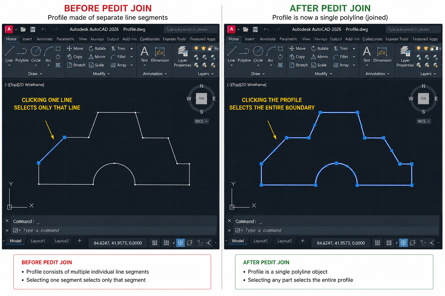
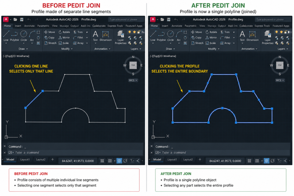
    AutoCAD profile comparison showing separate line segments versus unified closed polyline after PEDIT Join for 3D extrusion

    Use PEDIT Join whenever you are working with an existing 2D drawing where the profile was built from individual lines and arcs (as most 2D engineering drawings are) rather than a single polyline. Autodesk’s official guidance on converting lines to solids

    Read Supporting Article: How to Draw a Line from Its Midpoint in AutoCAD

    Full Step-by-Step: PEDIT Join

    1. Type PEDIT (or PE) and press Enter.
    2. AutoCAD prompts: Select polyline or [Multiple]:. If working with multiple separate objects, type M and press Enter to use Multiple mode.
    3. Select all the line and arc segments that make up your profile. Press Enter to confirm the selection.
    4. AutoCAD asks whether to convert non-polyline objects. Type Y and press Enter to convert all selected lines and arcs to polyline segments.
    5. AutoCAD prompts with edit options. Type J (Join) and press Enter.
    6. AutoCAD prompts: Specify fuzz distance or [Jointype]:. The fuzz distance is the maximum gap between segment endpoints that AutoCAD will bridge to join them. For clean drawings, the default (0 or a very small value) is fine. For drawings with tiny gaps, type a small value such as 0.001 and press Enter.
    7. AutoCAD joins the segments and reports how many segments were joined. Press Enter to accept and exit PEDIT.
    8. Type C (Close) as an additional PEDIT option if the joined polyline is not yet explicitly closed back to its start point.

    What the Fuzz Distance Does:  The fuzz distance in PEDIT Join defines the maximum gap between two segment endpoints that AutoCAD considers close enough to join. If two lines appear to meet but have a 0.5mm gap because OSNAP was off when they were drawn, setting the fuzz distance to 1 will bridge that gap. Setting it too high (e.g. 100) will join segments that were never meant to connect. Start with a small value and increase only if the join fails at a lower value.

    Verifying the Join Was Successful

    After PEDIT Join, click anywhere blank to deselect, then click the profile once. If it highlights as a single object (the entire outline becomes selected at once), the join was successful. If individual segments highlight separately, some joins were not made. Run PEDIT Join again on the un-joined segments, or investigate why those endpoints are not connecting using the endpoint OSNAP to check for gaps.

    Method 3: Using REGION to Create a Profile from Any Closed Boundary

    The REGION command converts any collection of connected objects that form a closed boundary — regardless of whether they are lines, arcs, polylines, splines, or a mix — into a single flat 2D region object. A region is essentially a solid surface with zero thickness. It is always treated as a closed boundary by AutoCAD’s solid creation commands, making it an extremely reliable alternative to polyline profiles.

    When to Use REGION Instead of PEDIT

    Use REGION when the profile boundary is made up of many different object types that cannot be easily joined with PEDIT (for example, a mix of splines, arcs, and lines). Also use REGION when you need to create profiles with holes (islands) — REGION supports Boolean operations between regions to create complex profiles with internal cutouts before extruding. This is covered in detail in the islands section below.

    Full Step-by-Step: REGION Command

    1. Ensure all the objects forming the closed boundary are genuinely connected at their endpoints. Use OSNAP endpoint markers to verify that each connection is precise.
    2. Type REGION (or REG) and press Enter.
    3. Select all objects that form the closed boundary. Press Enter.
    4. AutoCAD reports: 1 loop extracted. 1 Region created. (The number will vary depending on how many closed loops you selected.)
    5. The selected objects are converted into a flat region object. The original line and arc geometry is replaced by the region.
    6. The region is now ready for EXTRUDE, REVOLVE, LOFT, or SWEEP.
    Important: REGION Replaces the Original Objects:  When you run REGION, the original lines, arcs, and polylines are deleted and replaced by the region object. If you need to keep the original 2D geometry, copy it to a separate layer before running REGION, then set that layer to No Plot or freeze it after the region is created.

    Method 4: Using BOUNDARY to Auto-Detect Closed Areas

    The BOUNDARY command is AutoCAD’s most automated profile creation tool. It works like the HATCH boundary detection algorithm: you click inside a closed area and AutoCAD automatically traces the boundary of that area, creating a new polyline or region on top of the existing geometry. The original geometry is preserved, and the new profile object is placed precisely on top of it.

    BOUNDARY is particularly useful when you have a complex drawing with overlapping geometry and you want to create a clean profile from a specific enclosed area without manually selecting and joining all the boundary segments.

    Full Step-by-Step: BOUNDARY Command

    1. Type BOUNDARY (or BO) and press Enter. The Boundary Creation dialogue opens.
    2. Under Object Type, choose Polyline (for a closed polyline profile) or Region (for a region profile). Polyline is the default and usually the better choice.
    3. Click Pick Points in the dialogue.
    4. Click inside the enclosed area whose boundary you want to trace. AutoCAD analyses the geometry and highlights the detected boundary.
    5. Press Enter to confirm. AutoCAD creates the new polyline or region object precisely on top of the detected boundary.
    6. The new profile is now a separate, clean, closed polyline or region ready for extrusion.
    BOUNDARY vs PEDIT Join — When to Use Each:  Use PEDIT Join when you have a clearly defined set of connected segments that form your profile and you want to weld them into one polyline. Use BOUNDARY when the profile area is defined by intersecting geometry (lines that cross each other, overlapping shapes) and you want AutoCAD to auto-detect the enclosed area. BOUNDARY is faster and less error-prone for complex overlapping geometry.

    Validating Your Profile Before Extruding

    Before invoking any solid creation command, always validate the profile. This five-step check takes under a minute and prevents the frustration of discovering problems after the solid has been generated incorrectly.

    Validation CheckHow to Perform ItWhat It Confirms
    Check object countClick the profile once. Only ONE object should highlight. If multiple separate segments highlight, PEDIT Join or REGION is needed.Profile is a single unified object, not multiple separate segments
    Check closureType PEDIT, select the polyline. If the option ‘Close’ appears (rather than ‘Open’), the polyline is not explicitly closed. Type C to close it.Profile endpoint connects back to start point — the polyline is geometrically closed
    Check planarityType LIST, select the profile, press Enter. Check that all vertex Z coordinates are identical. If any differ, the profile is not flat and will extrude unpredictably.Profile lies entirely on a single flat plane — no accidental Z deviations
    Check for self-intersectionsZoom in and orbit around the profile. Look for any segments that cross each other within the boundary.Profile boundary does not cross itself, which prevents solid creation
    Test extrude directionIn the isometric viewport, check the UCS icon orientation. The extrusion will go perpendicular to the current UCS XY plane. Confirm this is the intended direction.Extrusion will go in the correct direction relative to the profile plane

    Choosing the Right Solid Creation Command for Your Profile

    If Your Profile Is…Use This CommandWhy
    A cross-section that is the same all the way through the depth of the partEXTRUDEPushes the profile perpendicular to its plane by a specified depth. Best for prismatic parts, plates, beams, and any constant cross-section shape.
    A half-section of a rotationally symmetric part (shaft, cylinder, cone, bowl)REVOLVERotates the profile around a specified axis through any angle. Creates perfectly symmetric solids of revolution without needing a full cross-section profile.
    A cross-section that changes shape from one end of the part to the otherLOFTBlends between two or more cross-section profiles placed at different positions. Correct for tapered parts, transitions, and organic shapes.
    A consistent cross-section that follows a curved or custom pathSWEEPFollows the profile along any drawn path (arc, polyline, spline, circle). Correct for pipe bends, handrails, extruded mouldings, and curved extrusions.
    A flat face on an existing solid that needs a boss or pocket addedPRESSPULLDetects enclosed regions on solid faces and directly adds (pull) or removes (press) material. Fastest for adding features to existing solids.

    EXTRUDE: Straight, Tapered, and Path-Based Profiles

    EXTRUDE is the most commonly used solid creation command for profile-based 3D modelling. It takes a closed profile and creates a solid by sweeping it perpendicular to its plane for a specified distance.

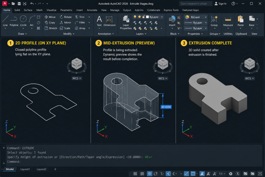
    AutoCAD EXTRUDE workflow showing closed polyline profile, extrusion preview, and completed 3D solid in three stages

    Standard EXTRUDE: Step-by-Step

    1. Prepare and validate the profile (closed polyline, circle, ellipse, or region).
    2. Type EXT (EXTRUDE) and press Enter.
    3. Select the profile. Press Enter.
    4. Type the extrusion height (depth) value and press Enter. Positive value extrudes in the positive Z direction of the current UCS; negative extrudes in the negative Z direction.
    5. The 3D solid appears. Inspect in isometric view.

    EXTRUDE with Taper Angle

    A taper angle makes the profile shrink or expand as it extrudes, creating a draft angle. Essential for injection moulded parts, castings, and components that need release angles.

    1. Type EXT, select profile, press Enter.
    2. Type T (Taper angle) and press Enter.
    3. Enter the taper angle in degrees. Positive tapers inward (profile shrinks toward the top), negative tapers outward.
    4. Enter the extrusion height. The solid tapers along its length.

    EXTRUDE Along a Path

    Instead of extruding perpendicular to the profile plane, EXTRUDE with the Path option follows a drawn curve:

    1. Draw the path (a line, arc, polyline, or spline) in the drawing.
    2. Type EXT, select the profile, press Enter.
    3. Type P (Path) and press Enter.
    4. Click the path object. The profile extrudes along the full length of the path.

    REVOLVE: Profiles That Rotate Around an Axis

    REVOLVE creates a 3D solid by rotating a profile around a defined axis. Use it for any rotationally symmetric component: shafts, bolts, cylinders, cones, flanges, bottles, and turned parts.

    Creating the Correct Profile for REVOLVE

    The profile for REVOLVE is the half-section cross-section: draw only the right half of the outline (from the centre axis outward). The profile does not need to be closed if it lies entirely on one side of the intended rotation axis — AutoCAD will close the revolution automatically. However, a closed half-profile produces more predictable results.

    Full Step-by-Step: REVOLVE

    1. Draw the half-section profile as a closed polyline or as connected lines/arcs.
    2. Optionally draw an axis line along the centre of revolution, or note which edge of the profile will be the axis.
    3. Type REV (REVOLVE) and press Enter.
    4. Select the profile. Press Enter.
    5. At Specify axis start point: click the first point of the revolution axis.
    6. Click the second axis point, or type X, Y, or Z to revolve around the corresponding world axis.
    7. Enter the angle of revolution. Type 360 for a complete solid, or a partial angle for a sector.

    LOFT: Multiple Profiles Blended into One Solid

    LOFT creates a 3D solid that transitions smoothly between two or more cross-section profiles. Each profile defines the shape of the solid at that cross-sectional location, and LOFT blends between them.

    Setting Up Profiles for LOFT

    All profiles used in LOFT must be either all closed (to produce a solid) or all open (to produce a surface). You cannot mix closed and open profiles in a single LOFT operation. Each profile must lie on its own plane and the planes should generally be parallel for predictable results (though they do not have to be).

    Full Step-by-Step: LOFT

    1. Draw at least two cross-section profiles at different positions along the intended axis of the solid.
    2. Type LOFT and press Enter.
    3. Select the profiles in order from one end to the other. Selecting out of sequence produces twisted results. Press Enter when all profiles are selected.
    4. At the Loft Options prompt, press Enter for Cross-sections only (the default, which produces the smoothest blend).
    5. In the Loft Settings dialogue, choose Smooth Fit for organic blends, Ruled for linear face transitions, or Normal to start and end sections for blends that are perpendicular to the end profiles.
    6. Click OK. The lofted solid appears.

    SWEEP: Profiles Along a Curved or Custom Path

    SWEEP extrudes a cross-section profile along any defined path object: a line, arc, circle, polyline, ellipse, or spline. Unlike EXTRUDE (which always goes perpendicular), SWEEP follows the geometry of the path exactly, making it ideal for curved extrusions such as pipe bends, architectural mouldings, and spiral springs.

    Profile and Path Placement for SWEEP

    The profile does not need to be drawn at the start of the path, but it must lie on a plane perpendicular to the path at the start point. AutoCAD automatically relocates the profile to the start of the path when SWEEP is run. If the profile and path are on the same plane, SWEEP handles the orientation automatically.

    Full Step-by-Step: SWEEP

    1. Draw the closed 2D cross-section profile (the shape that will be swept).
    2. Draw the path the profile will follow (line, arc, polyline, or spline).
    3. Type SWEEP and press Enter.
    4. Select the profile. Press Enter.
    5. Select the path object. AutoCAD sweeps the profile along the full path length, creating the 3D solid.

    Handling Nested Profiles and Profiles with Islands (Holes)

    Many mechanical components have profiles with holes or internal cutouts — a plate with mounting holes, a hollow tube cross-section, or a washer outline. These are called profiles with islands. AutoCAD handles them differently depending on whether you use the direct EXTRUDE approach or a REGION Boolean approach.

    Method A: EXTRUDE Then SUBTRACT (Most Reliable)

    The most straightforward and reliable method for profiles with holes:

    1. Extrude the outer profile as normal to create the solid body.
    2. Create separate solid cutters for each hole (cylinders for round holes, boxes for rectangular pockets). Position them at the correct locations.
    3. Use SUBTRACT to cut the cutter solids from the body solid.

    Method B: REGION Boolean Operations Before Extruding

    If you prefer to define the complete profile including holes before extruding, use REGION Boolean operations:

    1. Create a REGION from the outer boundary.
    2. Create separate REGIONs from each hole or cutout boundary.
    3. Type SU (SUBTRACT), select the outer region as the body, press Enter, then select all inner regions as cutters, press Enter.
    4. The result is a single region with holes already cut into it.
    5. Extrude this compound region. The extruded solid will have holes running through it.
    Which Method Is Better?  Method A (EXTRUDE then SUBTRACT) is simpler and less prone to errors. Method B (REGION Boolean then EXTRUDE) is useful when you want to verify the 2D profile visually before extruding, or when the profile shape changes because of the holes (e.g., thin walls between adjacent holes require careful profile validation before extruding).

    Converting Existing Objects to Solids (CONVTOSOLID and THICKEN)

    Sometimes you have existing AutoCAD objects that are not profiles but need to become solids. Two commands handle specific conversion scenarios:

    CONVTOSOLID: Converting Meshes and Polyfaces

    CONVTOSOLID converts AutoCAD mesh objects, polyface meshes, and zero-width closed polylines with thickness into 3D solids. Type CONVTOSOLID, select the object, press Enter. If the conversion is possible, AutoCAD creates a solid from the selected object. This is useful when working with imported mesh geometry from older files or from other software.

    THICKEN: Converting Surfaces to Solids

    THICKEN converts a 2D surface object (created by EXTRUDE or LOFT on an open profile) into a 3D solid by adding thickness. Type THICKEN, select the surface, press Enter, enter the thickness value. AutoCAD creates a solid of the specified thickness from the surface. This is particularly useful when you have created a complex surface shape using LOFT or SWEEP on open profiles and then need to give it physical thickness for manufacturing purposes.

    Profile Troubleshooting: Why Won’t AutoCAD Extrude My Profile?

    This section is the one that most AutoCAD tutorials skip entirely and that users search for most desperately. Here is a complete reference for every common profile-to-solid failure mode, what causes it, and exactly how to fix it.

    Error or SymptomRoot CauseDiagnosis MethodFix
    EXTRUDE creates a surface instead of a solidProfile is an open polyline or open spline rather than a closed boundaryClick profile. Type PEDIT, check if ‘Close’ option appears (means it is open)Type PEDIT > Close to close the polyline, or use REGION to convert the boundary to a closed region
    EXTRUDE gives error: ‘Object is not a closed loop’Profile consists of separate line and arc segments that are not joined into a single objectClick profile. If individual segments highlight separately, they are not joinedUse PEDIT > Multiple > Join to weld all segments into one polyline. Set fuzz distance to 0.001 if needed.
    Profile appears closed visually but EXTRUDE still creates a surfaceTiny gap between two segment endpoints invisible at normal zoomZoom in extreme (type Z, E for extents then zoom in 10x) to the endpoint area and check for gaps with endpoint OSNAPMove one endpoint to exactly meet the other using MOVE and endpoint OSNAP, or use PEDIT Join with a small fuzz distance
    EXTRUDE fails with ‘Object is not a region or 2D curve’Profile is a 3D object or has Z-coordinate variation across its pointsType LIST on the profile. Check if any vertex Z values differ from the othersUse FLATTEN command (or set all vertices to Z=0 manually with PEDIT) to make the profile truly planar
    LOFT creates a twisted solid between profilesProfiles were selected out of sequential orderInspect the solid. Twisting indicates profiles were joined in the wrong orderUndo and repeat LOFT. Select profiles strictly from one end to the other in order
    REVOLVE creates a surface with a gap rather than a closed solidProfile crosses the revolution axis or the axis is positioned inside the profileVisually check profile position relative to axis lineMove the profile so its edge aligns with but does not cross the intended axis, or use an axis defined by two points that lies exactly along the profile edge
    SWEEP produces an unexpected shape or the profile appears tiltedProfile is not perpendicular to the path at the sweep start pointCheck the angle between the profile plane and the path start tangent in isometric viewRotate the profile 90 degrees to align its plane perpendicular to the path direction before sweeping
    BOUNDARY detects wrong area or does not closeBackground geometry has overlapping or unclosed segments near the picked pointUse ZOOM to inspect the area closely. Look for stray lines or unclosed segments nearbyClean up the background geometry. Delete stray lines and close any open segments before running BOUNDARY again

    Frequently Asked Questions (FAQ)

    How do you make a 3D solid from a profile outline in AutoCAD?

    To make a 3D solid from a profile outline in AutoCAD: (1) Ensure the profile is a single closed object — a closed polyline, circle, ellipse, or REGION. Use PEDIT > Join to combine separate lines and arcs, or BOUNDARY to auto-detect a closed boundary. (2) Confirm the profile is on the correct UCS plane. (3) Type EXT (EXTRUDE), select the profile, press Enter, and type the extrusion depth. For rotationally symmetric parts, use REVOLVE; for profiles following a curve, use SWEEP; for profiles that blend between shapes, use LOFT.

    Why does AutoCAD create a surface instead of a solid when I use EXTRUDE?

    AutoCAD creates a surface instead of a solid when the profile passed to EXTRUDE is an open polyline, arc, or spline rather than a closed boundary. EXTRUDE requires a completely closed profile to produce a solid. To fix it: type PEDIT, select the polyline, choose Close to close it if its start and end points are the same location but not explicitly connected. If the profile consists of separate segments with gaps between them, use PEDIT > Join with a small fuzz distance, or use REGION to convert the entire closed boundary to a region object.

    What is the PEDIT Join command in AutoCAD?

    PEDIT Join (Polyline Edit Join) is an AutoCAD command that converts a collection of separate connected line and arc segments into a single unified polyline. It is the primary method for preparing profile outlines for 3D extrusion. To use it: type PEDIT, type M for Multiple mode, select all the segments forming the profile boundary, press Enter, type Y to convert to polylines, type J (Join), set a fuzz distance (0 for clean drawings, a small value like 0.001 for drawings with tiny gaps), and press Enter. The result is a single closed polyline ready for EXTRUDE.

    What is the difference between REGION and a closed polyline in AutoCAD?

    Both are valid profile types for 3D solid creation commands, but they have different properties. A closed polyline is a 1D curve that traces a closed boundary. A REGION is a flat 2D planar object that has area and is treated as a filled surface. REGIONs support Boolean operations (SUBTRACT, UNION, INTERSECT) between each other, allowing complex profiles with holes to be defined before extruding. Closed polylines cannot be Booleans-operated before extrusion. For simple solid profiles, either works. For complex profiles with internal cutouts, REGION is often more efficient.

    What is the BOUNDARY command in AutoCAD?

    The BOUNDARY command (BO) in AutoCAD automatically detects and traces the boundary of any closed area in the drawing. You click inside the area and AutoCAD creates a new polyline or region object following the exact perimeter of that enclosed space. The original geometry is preserved and the new profile object is created on top of it. BOUNDARY is faster than PEDIT Join for complex areas defined by intersecting geometry, and it preserves all the original drawing lines and arcs unchanged.

    How do I extrude a profile with holes in AutoCAD?

    To extrude a profile with holes in AutoCAD, use one of two methods. Method 1 (simpler): extrude the outer profile to create the body solid, then create cylinder or box solids at the hole positions and use SUBTRACT to cut them from the body. Method 2 (pre-extrusion): create a REGION from the outer boundary, create REGIONs from each hole boundary, use SUBTRACT to subtract the hole regions from the outer region, then EXTRUDE the resulting compound region. The extruded solid will have the holes built in.

    Why does AutoCAD extrude in the wrong direction?

    AutoCAD extrudes perpendicular to the current UCS XY plane in the positive Z direction by default. If the extrusion goes in the wrong direction, either the UCS is oriented incorrectly for the operation, or you entered a positive depth when a negative value was needed (or vice versa). To fix: type UCS > W to reset to World UCS, verify the UCS icon X and Y directions in your viewport match your expected orientation, then re-run EXTRUDE. Enter a negative depth value to extrude in the opposite direction from default.

    Conclusion

    Making a 3D solid from a profile outline in AutoCAD is fundamentally a two-stage process: get the profile right, then choose the right creation command. Of those two stages, getting the profile right is the one that determines whether the operation succeeds or fails, and it is the stage that most tutorials skip entirely.

    A correctly prepared profile — a single closed polyline, a circle, an ellipse, or a REGION — will extrude, revolve, loft, or sweep reliably and produce exactly the solid you intended. A poorly prepared profile will fail silently, produce a surface instead of a solid, or extrude in the wrong direction. The four preparation methods in this guide (POLYLINE from scratch, PEDIT Join, REGION, and BOUNDARY) cover every scenario from clean new drawings to complex imported geometry.

    The troubleshooting table at the end of this guide covers every common failure mode. Bookmark it and use it as a reference whenever a profile refuses to extrude as expected. In most cases the diagnosis takes less than a minute and the fix takes less than two.

    Continue learning AutoCAD 3D: read How to Create a 3D Model from 2D Views for the complete orthographic-to-solid workflow, or return to the complete AutoCAD Tutorials for Beginners and Professionals guide.
  • Why Is My AutoCAD Ribbon Empty? (All Fixes 2026)

    Why Is My AutoCAD Ribbon Empty? (All Fixes 2026)

    You open AutoCAD and the ribbon is empty, blank, or showing the message “The Ribbon does not have any tabs or panels currently loaded“. The drawing area is there, the command line is there, but the entire ribbon at the top of the screen has vanished. Nothing works the way it should.

    This is one of the most common AutoCAD problems reported by users at every experience level. The good news is that it almost always has a quick fix. The reason it feels so frustrating is that there are several possible causes, and if you try the wrong fix first, you can waste significant time. This guide eliminates that guesswork.

    It covers every reason an AutoCAD ribbon disappears or goes blank, in order from the most common and easiest to fix to the most complex. For each cause, there is a clear, numbered step-by-step solution. A diagnostic table at the top helps you match what you are seeing on screen to the exact fix you need.

    Quick Fix:  If you just need the ribbon back immediately, type RIBBON in the command line and press Enter. If that does not work, check that the correct workspace is loaded using the gear icon in the bottom-right status bar. These two steps fix the majority of empty ribbon problems in under 30 seconds.

    Diagnose Your Ribbon Problem: Match Your Symptom to the Fix

    Before working through individual fixes, use this diagnostic table to identify which cause matches what you are seeing. This saves time and gets you to the right solution immediately.

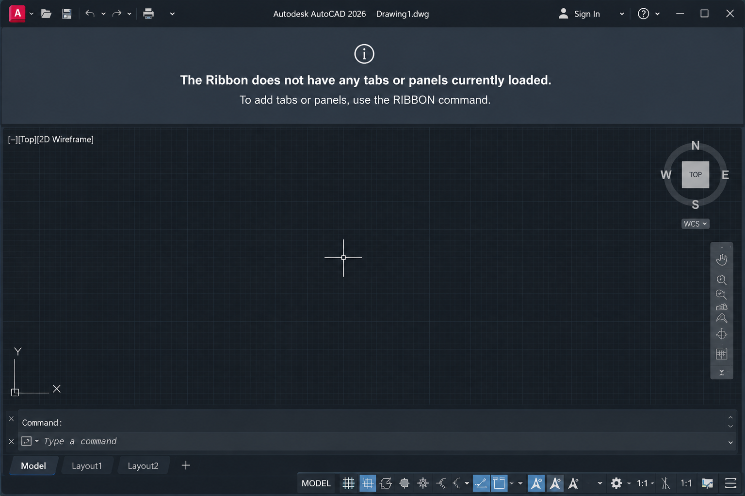
    AutoCAD blank ribbon showing the message 'The Ribbon does not have any tabs or panels currently loaded' error state
    What You See on ScreenMost Likely CauseGo to Fix
    Ribbon area is completely absent. No tabs, no panels, no blank bar.Ribbon was turned off via command or menuFix 1: RIBBON Command
    Ribbon area shows a blank/empty bar with the message: ‘The Ribbon does not have any tabs or panels currently loaded’Wrong workspace selected, or corrupted CUIX fileFix 2: Workspace, then Fix 6: CUIX File
    Entire AutoCAD interface is full-screen with no ribbon, no status bar, no toolbars at allClean Screen mode is activeFix 3: Clean Screen Mode
    A thin ribbon title bar is visible at the top but the panels collapse when you move the mouse awayRibbon is set to Auto-Hide modeFix 4: Auto-Hide Setting
    Ribbon is present but has drifted or is floating as a separate window, partially off-screenRibbon was undocked and dragged off-screenFix 5: Undocked Ribbon
    Ribbon was working fine until AutoCAD was updated or a new plugin was installedCUIX file corrupted or overwritten by update or pluginFix 6: Reset CUIX File
    Ribbon blank only for certain toolsets (e.g. Architecture, Mechanical) not standard tabsIndustry toolset not installed or profile settings incorrectFix 6 or Fix 7: Profile Reset
    Ribbon has been blank since a settings migration from an older version of AutoCADUser profile from previous version incompatibleFix 7: Reset User Profile
    All above fixes have been tried and nothing worksDeep corruption in AutoCAD installation or profileFix 8: Reset to Defaults or Reinstall

    Fix 1: The Ribbon Was Accidentally Turned Off (RIBBON Command)

    This is the most common cause of a missing AutoCAD ribbon and the easiest fix. The ribbon can be toggled off accidentally by pressing Ctrl + 0 (which activates Clean Screen), by clicking the X button on the ribbon, or by navigating to Tools > Palettes > Ribbon and unchecking it. Many users do this unintentionally while reaching for a nearby keyboard shortcut.

    Step-by-Step Fix

    1. Click anywhere in the AutoCAD command line at the bottom of the screen to make sure it is active.
    2. Type RIBBON and press Enter.
    3. The ribbon should immediately reappear at the top of the screen.
    4. If the ribbon reappears but is not the correct workspace, continue to Fix 2.

    Alternatively, if the classic menu bar is visible at the top (Tools, Draw, Modify etc.), go to Tools > Palettes > Ribbon and click to enable it. If the menu bar is not visible either, the command line is your only entry point.

    Command Line Not Visible?  If the command line itself has disappeared alongside the ribbon, press Ctrl + 9 to restore it. Once the command line is back, type RIBBON and press Enter to restore the ribbon.

    Fix 2: Wrong Workspace Selected

    AutoCAD uses workspaces to define the arrangement of the interface: which ribbon tabs are visible, where the toolbars sit, and what the screen layout looks like. If the wrong workspace is loaded, the ribbon may appear completely blank or show only partial tabs. This is one of the most common causes of the message “The Ribbon does not have any tabs or panels currently loaded“.

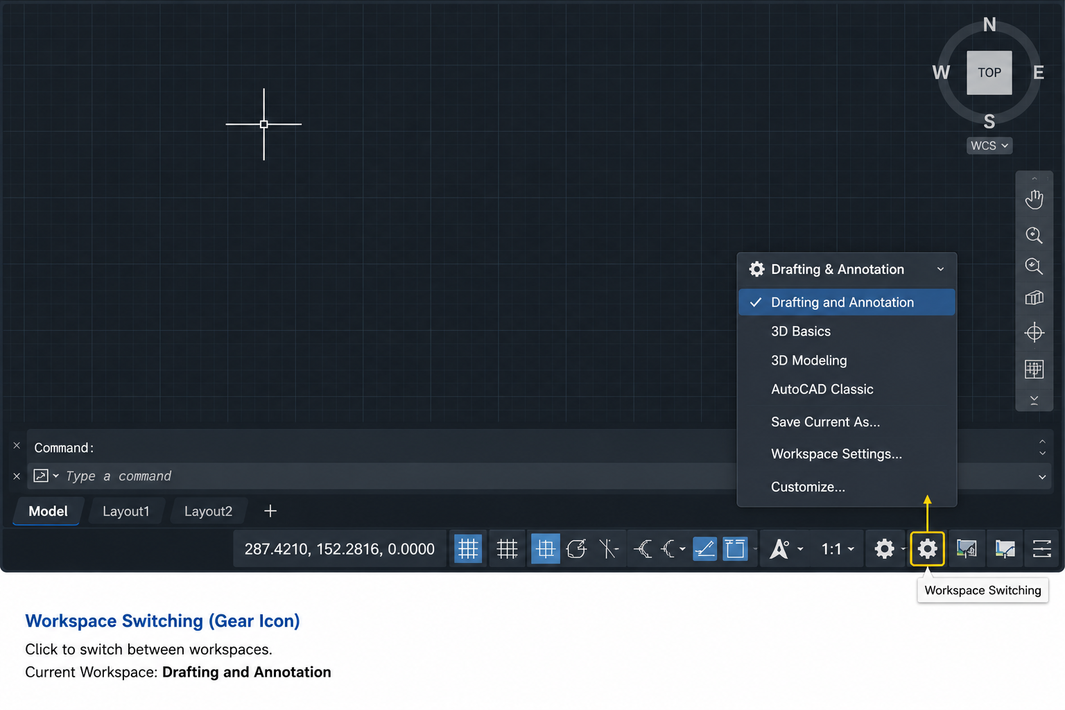
    AutoCAD workspace switching gear icon in status bar with workspace dropdown showing Drafting and Annotation option highlighted

    Step-by-Step Fix

    1. Look at the status bar at the very bottom-right of the AutoCAD screen. Find the gear icon (Workspace Switching).
    2. Click the gear icon to open the workspace menu.
    3. Select one of the standard workspaces: Drafting and Annotation (for 2D work), 3D Modelling (for 3D work), or 3D Basics (simplified 3D interface).
    4. If the ribbon does not load, try switching to a different workspace first, then switching back to your preferred workspace.
    5. Alternatively, type WORKSPACE in the command line, press Enter, then type RESTORE followed by the workspace name (e.g. RESTORE “Drafting & Annotation”).

    If the gear icon is not visible in the status bar, right-click the status bar and make sure Workspace Switching is ticked. Alternatively, type WSCURRENT in the command line and press Enter to see which workspace is currently active.

    After the Update Problem:  If the ribbon went blank after an AutoCAD update, a workspace settings migration often causes this. After updating, go to the workspace switcher, select the appropriate workspace, and then go to Tools > Workspaces > Save Current As to save a clean version of the workspace. This prevents the same issue occurring after the next update.

    Fix 3: AutoCAD Is in Clean Screen Mode

    AutoCAD’s Clean Screen mode maximises the drawing area by hiding all interface elements: the ribbon, toolbars, status bar, and palettes. It is designed for users who need maximum drawing space, particularly on smaller monitors. If you accidentally activated it, the entire interface appears to have vanished.

    The giveaway sign that you are in Clean Screen mode (rather than a genuine ribbon failure) is that the drawing area fills the entire screen right to the edges, with no interface elements visible anywhere, not even a thin title bar at the top.

    Step-by-Step Fix

    1. Press Ctrl + 0 (zero) to toggle Clean Screen mode off. This is a single keyboard shortcut that toggles the mode on and off.
    2. The full interface including the ribbon should immediately reappear.
    3. Alternatively, look for the Clean Screen icon in the far bottom-right corner of the screen (a small double-headed arrow icon) and click it to toggle Clean Screen off.
    Quick Test:  Press Ctrl + 0 twice in quick succession. If the ribbon disappears and then comes back, you have confirmed that Clean Screen mode is being toggled. The first press activates it (hiding the ribbon), the second press deactivates it (restoring the ribbon). Now you know the shortcut that caused the problem and can avoid pressing it accidentally in the future.

    Fix 4: The Ribbon Is Set to Auto-Hide

    The AutoCAD ribbon auto-hide feature collapses the ribbon to just a thin title bar at the top of the screen when the cursor is not hovering over it, and expands it again when the cursor moves into the ribbon area. If this is active, the ribbon appears to be missing whenever the cursor is in the drawing area, leading users to believe something has gone wrong.

    The difference between Auto-Hide and a genuinely missing ribbon: when you move the cursor to the very top of the screen, a thin ribbon bar becomes visible momentarily and then disappears again. If this is what you are seeing, Auto-Hide is the cause, not a technical problem.

    Step-by-Step Fix

    1. Move your cursor to the very top of the screen until the ribbon appears.
    2. Look for the small upward-pointing arrow icon (pin/unpin icon) at the far right of the ribbon.
    3. Click this icon once to toggle Auto-Hide off. The ribbon will remain permanently expanded.
    4. Alternatively, right-click on the ribbon title bar at the top and look for the Auto-Hide Ribbon option. Uncheck it.

    Fix 5: The Ribbon Has Been Undocked and Is Floating Off-Screen

    The AutoCAD ribbon can be undocked from its default position at the top of the screen and dragged to any location, including off the visible screen area. If this has happened (usually after a monitor configuration change, a switch from dual to single monitor, or an accidental drag), the ribbon appears to be missing even though it technically still exists.

    Step-by-Step Fix

    1. Type RIBBON in the command line and press Enter. This restores and re-docks the ribbon to its default position at the top of the interface.
    2. If the ribbon reappears but is floating as a separate window, grab its title bar and drag it back to the top of the AutoCAD window until the docking highlight appears, then release to dock it.
    3. To lock the ribbon in place and prevent future accidental undocking, right-click on the ribbon title bar and select Lock Location > Floating Windows.

    Fix 6: Corrupted or Missing CUIX File

    The CUIX file (Customisation User Interface file) is what defines the entire AutoCAD ribbon: which tabs exist, which panels are in each tab, and which commands appear in each panel. The main file is called acad.cuix (or acadlt.cuix for AutoCAD LT). If this file becomes corrupted, is accidentally overwritten by a software update or third-party plugin, or cannot be located by AutoCAD, the ribbon loads blank or empty.

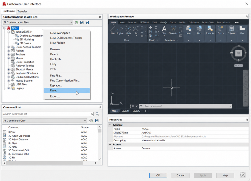
    AutoCAD CUI dialogue showing right-click context menu with Reset option highlighted to fix corrupted CUIX file and restore blank ribbon

    This is the most technically involved fix but also one of the most reliable. Resetting or reloading the CUIX file resolves the vast majority of persistent AutoCAD ribbon blank problems that the simpler fixes above do not address.

    Method 1: Reset the CUIX File via the CUI Command

    1. Type CUI in the command line and press Enter. The Customize User Interface dialogue box opens.
    2. In the top-left panel, you will see a list of loaded customisation files. Find ACAD (or the relevant product: ACADLT, C3D, etc.).
    3. Right-click on the ACAD entry.
    4. From the context menu, select Reset.
    5. A confirmation dialogue will appear. Click Yes to confirm the reset.
    6. Click OK to close the CUI dialogue.
    7. The CUIX file is now reset to its factory default state. Restart AutoCAD and check whether the ribbon has been restored.

    Method 2: Reload the CUIX File via CUILOAD

    1. Type CUILOAD in the command line and press Enter.
    2. Click the Browse button in the dialogue that appears.
    3. Navigate to the AutoCAD support folder. The default location for acad.cuix is typically:

    Windows: C:\Users\[username]\AppData\Roaming\Autodesk\AutoCAD [version]\[release]\[language]\Support\

    1. Select acad.cuix and click Load.
    2. If the file is already loaded, first select it in the Loaded Customisation Files list, click Unload, and then reload it using Browse.
    3. Click Close and check whether the ribbon has been restored.

    Method 3: Check the Support File Search Path

    If AutoCAD cannot find the CUIX file because the support file path is missing or incorrect (this commonly happens after installation of a new AutoCAD version or after moving user files to a new computer), you need to add the correct path to AutoCAD’s Options.

    1. Type OPTIONS (or OP) in the command line and press Enter.
    2. Go to the Files tab.
    3. Expand the Support File Search Path node.
    4. Click Add and browse to the folder containing your CUIX file.
    5. Click OK to close Options.
    6. Restart AutoCAD and verify the ribbon has been restored.
    Warning: Third-Party Plugins and the CUIX File:  Installing or uninstalling third-party AutoCAD plugins (add-ons, structural analysis tools, MEP tools, or manufacturer-specific libraries) can overwrite or corrupt the acad.cuix file. If the ribbon went blank immediately after installing a plugin, the CUI Reset method (Method 1 above) is almost always the solution. After resetting, you may need to re-install the plugin if you still need it, or contact the plugin developer for an updated version compatible with your AutoCAD version.

    Fix 7: Corrupted AutoCAD User Profile

    AutoCAD stores each user’s interface settings, support paths, and customisations in a user profile. If this profile becomes corrupted, particularly during version upgrades where settings are migrated from an older version, the ribbon may load blank or with missing panels even after the CUIX file has been reset.

    Step-by-Step Fix: Switch Profile and Reset

    1. Type OPTIONS (or OP) in the command line and press Enter.
    2. Go to the Profiles tab.
    3. In the Available Profiles list, select <<Unnamed Profile>> (or any profile that is not your current one).
    4. Click Set Current.
    5. Close Options and check whether the ribbon loads correctly on this profile.
    6. If the ribbon now works on the new profile, return to Options > Profiles and either delete the corrupted profile or click Reset to restore it to defaults.
    7. If switching profiles restores the ribbon, save the working profile as your new default using Set Current.
    Migration Tip:  When upgrading to a new version of AutoCAD, Autodesk recommends importing all settings from the previous version rather than only the profile. Importing only the profile, without the associated customisation files, is a known cause of blank ribbons in freshly upgraded installations. If you are setting up a new AutoCAD version, use the Migrate Custom Settings option from the Windows Start menu under the new AutoCAD version folder.

    Fix 8: AutoCAD Needs a Reset to Defaults

    If none of the above fixes have restored the ribbon, a full AutoCAD reset to factory defaults is the next step. This resets all settings, profiles, and customisations to the state they were in immediately after installation. It is a more drastic step because any custom settings, toolbars, aliases, or profiles you have built will need to be reconfigured, but it is very reliable at resolving deep corruption issues.

    Step-by-Step: Reset AutoCAD to Factory Defaults

    1. Close AutoCAD completely.
    2. In Windows, search for AutoCAD [version] in the Start menu.
    3. Look for Reset Settings to Default in the AutoCAD folder within the Start menu.
    4. Click Reset Settings to Default. A dialogue will ask you to backup your settings or reset without backup.
    5. Choose your preferred option and confirm the reset.
    6. Relaunch AutoCAD. It will start with a completely clean default configuration.
    7. If the ribbon now loads correctly, the issue was a deep corruption in the user settings. Rebuild only the custom settings you actually need rather than restoring from the corrupted backup.

    If even a full reset does not restore the ribbon, the issue likely lies in the AutoCAD installation itself. In this case, use the Autodesk desktop app or Programs and Features to run a Repair on the AutoCAD installation. If the repair fails, a full uninstall and clean reinstall of AutoCAD using the latest installer from your Autodesk account will resolve installation-level corruption.

    Why Does the AutoCAD Ribbon Keep Disappearing?

    If the AutoCAD ribbon keeps disappearing repeatedly rather than just once, there is usually an underlying cause that the temporary fix is not addressing. The most common reasons for a ribbon that keeps going missing are:

    AutoCAD Is Not Saving Workspace Changes

    By default, AutoCAD does not always save changes to the workspace automatically. If you restore the ribbon but AutoCAD is not configured to save the workspace state on exit, the ribbon position and visibility settings are lost the next time you open the program.

    The fix: type WSSETTINGS in the command line and press Enter to open the Workspace Settings dialogue. Enable Automatically Save Workspace Changes. This ensures any interface configuration changes you make are preserved between sessions.

    A Plugin or Script Is Modifying the Interface on Startup

    Some third-party plugins load their own CUIX customisation on AutoCAD startup, which can overwrite the standard ribbon. If the ribbon disappears every time you restart AutoCAD but is fine after being restored manually, check whether any startup suite scripts or plugins are loading on AutoCAD startup. Go to Tools > Load Application > Startup Suite and review what is loading automatically. Removing or updating a conflicting plugin often resolves the persistent ribbon problem.

    Incompatible Customisation Files from a Previous Version

    If customisation files (CUIX, MNS, MNR) from a previous version of AutoCAD are being loaded by the new version, they may not be fully compatible and can cause the ribbon to load incorrectly on every startup. Remove old version customisation files from the Support File Search Path in Options and recreate any custom tool entries in the current version’s native format.

    How to Stop Your AutoCAD Ribbon from Disappearing Again

    Once your AutoCAD ribbon is restored, three habits will prevent the problem from recurring:

    Prevention HabitHow to Implement ItWhat It Prevents
    Save your workspace explicitly after setting it upAfter configuring the interface the way you want it, go to Tools > Workspaces > Save Current As and save it with a clear name (e.g. ‘MY-2D-WORKSPACE’)Interface configuration being lost on restart or after an AutoCAD update
    Enable automatic workspace savingType WSSETTINGS, press Enter, and tick ‘Automatically Save Workspace Changes’Ribbon position and tab visibility changes being lost between sessions
    Keep a saved backup of your CUIX fileAfter setting up your customisations, export your profile via Options > Profiles > Export and save the .arg file to a safe locationHaving to rebuild all customisations from scratch after a CUIX corruption
    Be selective about which plugins you installBefore installing any third-party AutoCAD plugin or add-on, check that it is compatible with your specific AutoCAD version number on the developer’s websitePlugin-triggered CUIX corruption and ribbon blank problems after installation
    Use AutoCAD’s Migrate Settings correctly during upgradesWhen installing a new AutoCAD version, use the ‘Migrate Custom Settings’ option and choose to migrate all settings, not just the profileBlank ribbon in freshly upgraded AutoCAD installations due to incomplete settings migration

    Frequently Asked Questions (FAQ)

    Why is my AutoCAD ribbon empty?

    An empty AutoCAD ribbon is most commonly caused by one of five things: the ribbon was accidentally turned off (fix: type RIBBON in the command line and press Enter); the wrong workspace is selected (fix: use the gear icon in the status bar to switch to Drafting and Annotation); AutoCAD is in Clean Screen mode (fix: press Ctrl + 0 to toggle it off); the ribbon is set to Auto-Hide (fix: click the pin icon at the top-right of the ribbon title bar); or the CUIX file is corrupted (fix: type CUI, right-click ACAD, select Reset). The RIBBON command fixes the majority of cases immediately.

    How do I restore the AutoCAD ribbon?

    To restore a missing AutoCAD ribbon, type RIBBON in the command line and press Enter. If the ribbon reappears but shows the message ‘The Ribbon does not have any tabs or panels currently loaded’, switch to the correct workspace using the gear icon in the status bar and select Drafting and Annotation. If the ribbon still does not load correctly, reset the CUIX file by typing CUI, right-clicking the ACAD entry, selecting Reset, and restarting AutoCAD.

    What does ‘The Ribbon does not have any tabs or panels currently loaded’ mean in AutoCAD?

    This message means that AutoCAD has loaded but the ribbon definition file (the CUIX file) either cannot be found, has been corrupted, or has not been associated with the current workspace. The most reliable fix is to: first try switching workspaces using the gear icon in the status bar; if that does not work, type CUI in the command line, right-click the ACAD customisation file in the top-left panel, and select Reset. Restart AutoCAD after the reset.

    Why does my AutoCAD ribbon disappear every time I restart?

    If the AutoCAD ribbon disappears on every restart, it is almost always because AutoCAD is not saving your workspace settings between sessions. Type WSSETTINGS in the command line, press Enter, and enable ‘Automatically Save Workspace Changes’. Also verify that no startup script or third-party plugin is resetting the interface on launch by checking Tools > Load Application > Startup Suite.

    How do I fix the AutoCAD ribbon after an update?

    After an AutoCAD update, a blank ribbon is usually caused by a workspace settings migration issue. Switch to the Drafting and Annotation workspace using the gear icon in the status bar. If the ribbon loads, save this workspace using Tools > Workspaces > Save Current As. If the ribbon is still blank, type CUI, right-click ACAD, select Reset, and restart AutoCAD. For a permanent fix, type WSSETTINGS and enable automatic workspace saving.

    What is the CUIX file in AutoCAD and why does it affect the ribbon?

    The CUIX file (Customisation User Interface file) is an XML-based file that defines the entire AutoCAD ribbon: which tabs exist, which panels are in each tab, which commands are in each panel, and how toolbars and menus are structured. The main file is called acad.cuix. When this file is corrupted, accidentally overwritten by a plugin or update, or cannot be found by AutoCAD, the ribbon loads blank. The fix is to reset the CUIX file using the CUI command: right-click ACAD and select Reset.

    Conclusion

    A blank or empty AutoCAD ribbon is always fixable. The vast majority of cases resolve in under two minutes with either the RIBBON command, a workspace switch, or turning off Clean Screen mode. For the minority of cases involving a corrupted CUIX file or user profile, the fixes are still well within reach of any AutoCAD user who follows the numbered steps above.

    The key is to identify the correct cause first using the diagnostic table at the top of this article, then apply the right fix rather than working through every solution sequentially. Once the ribbon is restored, implementing the five prevention habits will stop the problem from recurring.

    Back to the full AutoCAD guide: AutoCAD Tutorials for Beginners and Professionals. Or continue with the next tutorial: How to Draw a Line from Its Midpoint in AutoCAD.

  • AutoCAD Tutorial for Beginners and Professionals 2026

    AutoCAD Tutorial for Beginners and Professionals 2026

    AutoCAD is the most widely used CAD software in the world. With over 4 million active subscribers globally and adoption across architecture, mechanical engineering, civil engineering, electrical design, and manufacturing, it is the tool that connects a design concept to a finished technical drawing more reliably than any other software in existence.

    Whether you have never opened a CAD program before, or you have been using AutoCAD for years and want to sharpen the professional skills that separate competent users from genuinely efficient ones, this guide covers the full spectrum. It is structured as a genuine beginner-to-professional learning path, not a reference list or a tips collection.

    You will learn what AutoCAD is, how its interface works, the foundational 2D drawing commands every user must know, how to set up drawings correctly from day one, how layers and blocks work and why they matter, how to produce professional-grade 3D models, how to print and plot drawings to industry standards, and how to apply AutoCAD skills across different engineering and design disciplines. The guide also covers the professional-level habits, keyboard shortcuts, and workflow principles that experienced AutoCAD users use daily but that beginners rarely encounter in online tutorials.

    Quick Answer:  AutoCAD is a Computer-Aided Design (CAD) software developed by Autodesk, first released in 1982. It is used to create precise 2D drawings and 3D models across engineering, architecture, and design. Learning AutoCAD typically takes 1 to 3 months to reach productive competence for 2D drafting, and 3 to 6 months to develop solid 3D modelling skills. It remains the most in-demand CAD skill in the global job market.

    What Is AutoCAD? A Complete Overview

    AutoCAD is a commercial computer-aided design and drafting software developed and marketed by Autodesk. First released on 1 December 1982 as one of the first CAD programs to run on personal computers, it has grown into the global standard for technical drawing and design across dozens of industries.

    At its core, AutoCAD allows users to create precise geometric drawings in 2D (lines, arcs, circles, polygons) and 3D (solid models, surfaces, meshes) with exact dimensional control that paper drawing and general-purpose illustration software cannot match. Every object in an AutoCAD drawing exists in coordinate space: it has a precise location, dimension, and relationship to other objects that can be measured, queried, and modified with engineering-level accuracy.

    What AutoCAD Is Used For

    AutoCAD is used to produce engineering drawings (mechanical component drawings, assembly drawings, schematics), architectural drawings (floor plans, elevations, sections, construction documents), civil engineering plans (site plans, road layouts, drainage networks, surveys), and electrical and piping diagrams (single-line diagrams, P&IDs, wiring schematics). In manufacturing, it is used to produce the 2D drawings that define component dimensions, tolerances, and surface finishes for machining and fabrication.

    Who Uses AutoCAD

    • Mechanical engineers and designers: Creating component drawings, assembly drawings, and manufacturing documentation
    • Architects: Producing construction documentation, floor plans, sections, and elevations
    • Civil engineers: Site layouts, road design, drainage plans, earthwork sections
    • Structural engineers: Reinforcement drawings, connection details, structural layout plans
    • Electrical designers: Circuit diagrams, cable routing plans, switchboard layouts
    • Interior designers: Space planning, furniture layouts, interior elevations
    • Students and trainees: Learning CAD fundamentals applicable to multiple disciplines

    AutoCAD Versions: Which One Should You Use?

    Autodesk releases a new version of AutoCAD annually, typically numbered by year. The current version is AutoCAD 2026 for the 2026/2026 subscription year. Understanding which version to use and which licensing option suits your situation is the first practical decision any new user must make.

    Version / OptionWho It Is ForKey FeaturesCost Model
    AutoCAD 2026 (full)Professional engineers, architects, and designers in industryFull 2D/3D capability, all industry toolsets, AutoCAD Web and Mobile, cloud collaborationSubscription: ~$2,230/year or ~$195/month (Autodesk 2026 pricing)
    AutoCAD LTUsers needing 2D drafting only, budget-conscious professionalsFull 2D drafting capability, no 3D modelling or custom programmingSubscription: ~$570/year (significantly lower cost)
    AutoCAD with ToolsetsSpecialists (mechanical, architecture, electrical, civil, plant, MEP)All standard AutoCAD features plus industry-specific symbol libraries, automated tools, and templatesSame subscription as full AutoCAD; toolsets included
    AutoCAD WebLight users, collaboration review, remote access to drawingsBrowser-based, core 2D commands, DWG compatibleIncluded with full AutoCAD subscription; limited standalone access
    AutoCAD MobileSite engineers, field access to drawingsView, markup, and basic editing on iOS/AndroidBasic free tier; full features with subscription
    AutoCAD for Students (Education)Students and educatorsFull AutoCAD functionalityFree for verified students and educators via Autodesk Education Community
    Key Recommendation:  If you are a student, get the free AutoCAD student licence from the Autodesk Education Community immediately. It is identical in functionality to the professional version and is valid for 1 year, renewable. If you are a professional evaluating AutoCAD, Autodesk offers a 30-day free trial of the full version. For 2D-only work in a professional setting, AutoCAD LT offers excellent value at less than one-quarter of the full version’s annual cost.

    Mastering the AutoCAD Interface

    The AutoCAD interface can look intimidating the first time you open it. There are panels, toolbars, tabs, a command line, and a drawing area that all compete for your attention simultaneously. The good news is that once you understand what each element does and why it is there, the interface becomes logical and highly efficient. Most experienced users find that AutoCAD’s interface structure is one of the most streamlined in the professional CAD world.

    Annotated AutoCAD interface screenshot showing Application Menu, Ribbon, Drawing Area, Command Line, and Status Bar labelled for beginners

    The Application Menu

    The Application Menu (the AutoCAD logo in the top-left corner) provides access to file management commands: New, Open, Save, Save As, Print, Publish, and Export. It also provides access to recent documents and drawing utilities. Think of it as AutoCAD’s equivalent of a File menu.

    The Quick Access Toolbar

    Directly to the right of the Application Menu is the Quick Access Toolbar (QAT), which contains the most frequently used file and undo commands: New, Open, Save, Save As, Print, Undo, and Redo. This toolbar can be customised to add any command you use frequently. Experienced users typically add the LAYER command and PLOT command to their QAT to save navigation time.

    The Ribbon

    The Ribbon is the large tabbed panel at the top of the interface, introduced in AutoCAD 2009 to replace the classic menu bar and toolbar system. It is organised into tabs (Home, Insert, Annotate, Parametric, View, Manage, Output, Add-ins, Collaborate) and within each tab, into panels containing related commands. The Home tab contains the most frequently used drawing and modification commands and is where most users spend the majority of their working time.

    If your ribbon has disappeared or appears empty, this is one of the most common AutoCAD problems for new users. It is easily resolved: type RIBBON in the command line and press Enter to restore it. Alternatively, check that the correct workspace is loaded under the Workspace Switching icon in the bottom-right status bar.

    The Drawing Area

    The Drawing Area is the large central space where your design exists. It represents an infinite 2D coordinate plane (or 3D space in the 3D workspace). The drawing area has no physical size: you draw at real-world scale (a 10-metre wall is drawn as 10 metres long) and control the print scale when plotting. The cursor crosshair tracks your position in coordinate space, displayed in the bottom-left status bar.

    The Command Line

    The Command Line at the bottom of the drawing area is the most important element of the AutoCAD interface for productive work. It is where you type command names and shortcuts (LINE, CIRCLE, TRIM, etc.), where AutoCAD prompts you for input, and where you enter dimensions, angles, and coordinates. Experienced AutoCAD users rely heavily on the command line because typing a command alias is almost always faster than clicking through the ribbon.

    AutoCAD’s command autocomplete means you only need to type the first few letters of a command to see a filtered list of options. Typing LA reveals LAYER and all layer-related commands. Typing TR reveals TRIM and TRIM-related commands. This is the single biggest productivity accelerator for new AutoCAD users to learn early.

    The Status Bar

    The Status Bar runs along the very bottom of the screen and contains toggleable drawing aids that profoundly affect how you interact with AutoCAD: SNAP (snaps cursor to a defined grid), GRID (displays a reference grid), ORTHO (constrains drawing to horizontal and vertical directions only), POLAR (constrains to specified angles), OSNAP (Object Snap: snaps to specific points on existing objects), and DYNAMIC INPUT (displays coordinates and prompts near the cursor).

    The most critical status bar setting to understand immediately is OSNAP (Object Snap). When OSNAP is active, moving the cursor near an existing object snaps it to precise points: endpoints, midpoints, centres, intersections, perpendiculars. Drawing without OSNAP active leads to inaccurate drawings where lines appear to connect but are actually slightly misaligned. Experienced AutoCAD users virtually always work with OSNAP on.

    Read related article on How to Draw a Line from Its Midpoint in AutoCAD

    Interface ElementKeyboard Shortcut / AccessWhat It DoesPro Tip
    Application MenuClick the AutoCAD logoFile management: New, Open, Save, Print, ExportAdd frequently used files to the recent documents list for one-click access
    RibbonType RIBBON to restore if missingAll drawing, modification, annotation, and output commands organised by tabRight-click any panel to add it to the Quick Access Toolbar
    Command LineCtrl + 9 to toggle on/offType commands, receive prompts, enter values and coordinatesPress F2 to expand the command history window
    Drawing AreaScroll wheel to zoom, middle-button drag to panYour design canvas: infinite 2D or 3D coordinate spaceType Z then Enter, then E then Enter (ZOOM EXTENTS) to fit drawing to screen
    Status BarFunction keys and status bar iconsToggle ORTHO, OSNAP, POLAR, SNAP, GRID, DYNAMIC INPUTF8 = ORTHO, F3 = OSNAP, F10 = POLAR TRACKING – memorise these three
    Properties PaletteCtrl + 1View and modify all properties of selected objectsUse to change layer, colour, linetype of multiple selected objects at once
    Layer Properties ManagerLA then EnterCreate, modify, and manage all layers in the drawingPin it as a docked palette for drawings with complex layer structures

    Setting Up Your Drawing Correctly from Day One

    One of the most common mistakes new AutoCAD users make is starting to draw without setting up their drawing environment properly. Drawing setup takes five to ten minutes and saves hours of correction work later. Experienced CAD professionals always work from a correctly configured template file, never from a blank default drawing.

    Setting Drawing Units

    Type UNITS (or UN) and press Enter to open the Drawing Units dialogue. Set the unit type (Decimal for metric engineering, Architectural for feet and inches) and precision (typically 0.00 for most engineering work, 0.000 for precision parts). Set the Insertion Scale to the units your drawing will use. Getting units wrong at setup means all dimensions will be incorrect and all blocks inserted from external sources will scale incorrectly.

    Setting Drawing Limits

    Type LIMITS to define the extent of your drawing. For most mechanical engineering work at 1:1 scale, set limits to match your drawing sheet size multiplied by your intended print scale. A drawing to be printed at 1:10 on an A1 sheet would have limits of 8,400 x 5,940 mm (A1 dimensions: 841 x 594 mm multiplied by 10).

    Setting Up Layers Before Drawing

    Never draw everything on Layer 0. Create your layer structure before drawing a single line. A well-structured layer scheme for a mechanical drawing might include layers for: Object Lines, Hidden Lines, Centre Lines, Dimensions, Text/Annotations, Hatching, Title Block, and Construction Lines. Each layer should have a defined colour, linetype, and lineweight. This investment at setup saves enormous time when editing, plotting, and sharing drawings.

    Using a Template File

    A drawing template file (.DWT) saves your standard layer structure, units settings, text styles, dimension styles, and title block layout so you do not need to recreate them for every new drawing. Create your company or personal standard template once and select it in the New Drawing dialogue whenever you start a drawing. Autodesk also provides standard template files (acad.dwt for imperial, acadiso.dwt for metric) as starting points.

    Essential AutoCAD Drawing Commands for Beginners

    The following AutoCAD drawing commands are the foundation of 2D drafting. Every AutoCAD user, from student to 30-year professional, uses these commands daily. Learn them thoroughly before moving to more advanced topics.

    CommandAliasWhat It DoesKey Input Tips
    LINELCreates straight line segments between specified pointsClick points or type coordinates. Press Enter or Esc to end. Type C then Enter to close a polygon back to the start point
    CIRCLECCreates a circle by centre point and radius (default), or by diameter, 2 points, or 3 pointsType C, click centre, type radius value and press Enter. Or type C, then D for diameter mode
    ARCACreates an arc defined by 3 points, or start/centre/end, or other combinationsDefault is 3-point arc. Right-click during ARC command to see all arc definition methods
    RECTANGLERECCreates a closed rectangular polyline by two diagonal corner pointsType REC, click first corner, type relative coordinates @width,height (e.g. @150,80) and Enter
    POLYGONPOLCreates a regular polygon with a specified number of sidesType POL, enter number of sides, specify centre, choose inscribed or circumscribed, enter radius
    POLYLINEPLCreates connected line and arc segments as a single objectUnlike LINE, a polyline is one object. Essential for shapes that need to be edited as a unit
    ELLIPSEELCreates an ellipse by axis endpoint and other axis distance, or by centreType EL, specify axis endpoint, second endpoint of same axis, then other axis distance
    SPLINESPLCreates a smooth curve through or near specified control pointsUsed for irregular curves. Click control points, press Enter to end
    HATCHHFills a closed area with a pattern (hatching) or solid fillType H to open Hatch Creation. Click inside a closed boundary. Select hatch pattern and scale
    POINTPOPlaces a point object at a specified locationSet point display style with PDMODE before placing points. Useful as construction references
    Critical Habit for Beginners:  Always use Object Snap (OSNAP) when drawing. Press F3 to toggle it on and off. With OSNAP on, your cursor will snap to the exact endpoints, midpoints, centres, and intersections of existing objects. Drawing without OSNAP leads to drawings that look correct visually but have tiny gaps and overlaps that cause major problems when trimming, hatching, or exporting to manufacturing. Professional AutoCAD users virtually never draw with OSNAP off.

    Essential AutoCAD Modify Commands

    Drawing commands create geometry. Modify commands are how you edit, refine, and complete that geometry. In professional AutoCAD use, modify commands are used more frequently than drawing commands. The ability to efficiently trim, extend, offset, mirror, array, and fillet geometry is what separates fast, accurate drafters from slow ones.

    CommandAliasWhat It DoesProfessional Tip
    ERASEEDeletes selected objectsSelect objects first, then press Delete key as an alternative to typing ERASE
    COPYCOCreates copies of selected objects at specified offsetsType CO, select objects, press Enter, specify base point, then displacement point. Use multiple copy mode for placing many copies
    MOVEMMoves selected objects to a new positionType M, select objects, press Enter, specify base point, then new position. Combine with OSNAP for precision
    ROTATERORotates selected objects around a specified base pointType RO, select objects, Enter, base point, then rotation angle. Add R for Reference to rotate to a specific angle
    SCALESCScales selected objects up or down from a base pointType SC, select objects, Enter, base point, scale factor. Use R (Reference) to scale by known dimensions
    MIRRORMICreates a mirrored copy of selected objects about a mirror lineType MI, select objects, Enter, two points defining mirror line, then Yes/No to delete original
    OFFSETOCreates a parallel copy of a line, arc, circle, or polyline at a specified distanceType O, specify offset distance, click the object, click the side to offset toward. One of the most-used commands in all of AutoCAD
    TRIMTRTrims objects back to cutting edges defined by other objectsType TR, press Enter (selects all objects as potential cutting edges), then click objects to trim. In AutoCAD 2021+, press Enter twice to use quick trim mode
    EXTENDEXExtends objects to meet a boundary edgeSame workflow as TRIM. In recent AutoCAD versions, holding Shift while in TRIM mode switches to EXTEND
    FILLETFCreates a rounded corner (arc) between two lines or edgesType F, set radius (R then value), then click the two lines to fillet. Set radius 0 to create sharp corners at intersections
    CHAMFERCHACreates a bevelled corner between two linesSimilar to FILLET but creates a flat bevel. Set distances with D option
    ARRAYARCreates a rectangular grid, polar ring, or path-distributed array of objectsType AR, select objects, Enter, choose array type. Associative arrays update when the source object changes
    STRETCHSStretches part of a drawing while keeping connections intactMust use a crossing selection (right to left selection window). Excellent for adjusting geometry without rebuilding it
    EXPLODEXBreaks blocks, polylines, and other compound objects into individual elementsUse with caution: exploded objects lose their block properties and polyline width information

    AutoCAD Layers: The Professional’s Most Important Tool

    If there is one AutoCAD concept that separates professional-quality drawings from amateur ones, it is the correct use of layers. Layers in AutoCAD function like transparent overlays: each layer contains specific types of drawing content, and layers can be turned on or off, locked, frozen, or plotted independently. A drawing with a well-designed layer structure is infinitely easier to edit, plot, and share than one where everything exists on a single layer.

    AutoCAD drawing comparison showing no layer structure versus professional layer structure with correct colours, linetypes, and lineweights

    How Layers Work

    Every object in an AutoCAD drawing exists on a layer. The default layer is Layer 0, which has special properties useful for block creation but should not be used for general drawing content. Each layer has four key properties that can be set independently:

    • Colour: Controls the display colour of objects on that layer. In plotting, colour is used to control lineweight through colour-based plot styles (CTB files).
    • Linetype: Controls whether lines are continuous, dashed, centre-line style, dotted, etc. Load linetypes with the LINETYPE command before assigning them to layers.
    • Lineweight: Controls the physical width of plotted lines. Set in millimetres (0.25mm for thin lines, 0.5mm for medium, 0.7mm for thick/outline lines is a common convention).
    • Plot/No Plot: Controls whether a layer is included in plots. Construction lines and reference layers should typically be set to No Plot.

    Professional Layer Naming Conventions

    Industry standards for AutoCAD layer naming vary by discipline and company, but all good naming conventions share the same principle: the layer name should immediately communicate what type of content is on that layer. A mechanical engineering drawing might use:

    Layer NameColourLinetypeLineweightContent
    OBJ-VISIBLEWhite / 7Continuous0.50 mmVisible object outlines and edges
    OBJ-HIDDENBlue / 5HIDDEN20.25 mmHidden lines (edges not visible in current view)
    OBJ-CENTRERed / 1CENTER20.25 mmCentre lines for holes, arcs, and symmetry axes
    DIMGreen / 3Continuous0.18 mmAll dimension objects
    TEXT-NOTESCyan / 4Continuous0.18 mmGeneral annotation and notes text
    HATCHMagenta / 6Continuous0.18 mmAll hatch and fill patterns
    TITLE-BLOCKWhite / 7Continuous0.50 mmTitle block and border geometry
    CONSTRUCTIONGrey / 8Continuous0.18 mmConstruction lines and reference geometry (No Plot)
    VIEWPORTGrey / 8Continuous0.18 mmPaper space viewport borders (No Plot)
    Professional Rule:  Never override layer properties at the object level (avoid using ‘BYLAYER’ exceptions) unless you have a specific reason. Keep all colour, linetype, and lineweight assignments set to BYLAYER. This means each object’s appearance is controlled entirely by its layer, making drawing-wide changes as simple as modifying a layer property once. Drawings where individual objects have overridden colours and linetypes are extremely difficult to maintain and edit professionally.

    Dimensions, Text, and Annotations in AutoCAD

    A drawing without dimensions and annotations is just a picture. AutoCAD dimensions are intelligent objects that measure and display the size of geometric features automatically, and they update when the geometry changes. Setting up dimension styles correctly before annotating is as important as setting up layers before drawing.

    Setting Up Dimension Styles

    Open the Dimension Style Manager (DIMSTYLE or D) to create and modify dimension styles. Key settings to configure include: text height (should match your drawing scale so text prints at 2.5-3.5mm high on the final sheet), arrow size (typically equal to or slightly larger than text height), precision (number of decimal places), tolerances (if applicable), and overall scale (DIMSCALE: set this to your drawing scale factor to ensure dimensions plot at the correct size).

    Key Dimensioning Commands

    • DIMLINEAR (DLI): Creates horizontal or vertical linear dimensions. The most commonly used dimension type.
    • DIMALIGNED (DAL): Creates a linear dimension aligned to an angled line.
    • DIMRADIUS (DRA): Dimensions the radius of an arc or circle.
    • DIMDIAMETER (DDI): Dimensions the diameter of a circle or arc.
    • DIMANGULAR (DAN): Measures the angle between two lines or between three points.
    • QDIM: Quickly creates a series of dimensions from selected objects simultaneously.
    • DIMCONTINUE (DCO): Creates a chain of dimensions from the endpoint of an existing dimension.
    • DIMBASELINE (DBA): Creates stacked dimensions all measured from a common baseline point.

    Text in AutoCAD: MTEXT vs DTEXT

    AutoCAD has two text objects: MTEXT (MT) (Multiline Text) and DTEXT (DT) (Dynamic Text, also called Single-Line Text). MTEXT is the preferred method for most annotation: it supports paragraph formatting, automatic wrapping within a defined boundary, and advanced text editing features. DTEXT is useful for quick single-line labels. Always create a Text Style (STYLE command) that references a standard font (SHX or TTF) and set a standard text height before creating text in any drawing.

    AutoCAD Blocks: Build Once, Use Forever

    AutoCAD blocks are one of the most powerful productivity tools in the software. A block is a named collection of objects grouped into a single reusable entity. Once defined, a block can be inserted into a drawing as many times as needed, at any scale and rotation, and any change to the block definition automatically updates all instances in the drawing.

    Why Blocks Matter for Professional Work

    In professional drafting, the same standard elements appear repeatedly: bolt holes, surface finish symbols, weld symbols, title blocks, door and window symbols, electrical components, piping fittings. Drawing these elements from scratch every time they appear is a massive waste of time. AutoCAD blocks allow you to create or import these standard elements once and insert them with a single command, at any scale and orientation, across any number of drawings.

    Creating a Block

    1. Draw the geometry that will form the block (draw it at 1:1 scale, centred on or near the origin).
    2. Type BLOCK (B) and press Enter to open the Block Definition dialogue.
    3. Enter a name for the block (descriptive and unique, e.g. M8-HOLE-SYMBOL or SURFACE-FINISH-125).
    4. Specify the Base Point: the insertion handle for the block. Pick a logical point (bottom-left corner, centre, or a specific snap point).
    5. Select Objects: select all the geometry that should form the block.
    6. Choose block settings: decide whether to convert selected objects to a block, retain them, or delete them.
    7. Click OK. The block is now defined in the drawing and can be inserted with the INSERT (I) command.

    Dynamic Blocks: The Professional Standard

    Dynamic blocks extend standard blocks with parameters and actions that allow a single block to represent multiple configurations. A dynamic block for a bolt, for example, might allow the user to choose bolt length from a drop-down list by clicking the block after insertion. A door swing block might allow the swing angle to be adjusted by dragging a grip. Creating dynamic blocks requires the Block Editor (BEDIT command) and is an intermediate-to-advanced AutoCAD skill, but using existing dynamic blocks is straightforward and significantly accelerates drafting.

    Master AutoCAD Keyboard Shortcuts: The Complete Reference Table

    Keyboard shortcuts are the single most effective way to increase AutoCAD productivity. Experienced AutoCAD users rarely click the ribbon for common commands: they type aliases in the command line. The difference in speed between a user who draws by clicking ribbon icons and one who types command aliases is dramatic: alias users are typically 30 to 50 percent faster on equivalent tasks.

    Shortcut / AliasFull CommandCategoryWhat It Does
    LLINEDrawingCreate line segments
    CCIRCLEDrawingCreate circle
    AARCDrawingCreate arc
    RECRECTANGLEDrawingCreate rectangle
    PLPOLYLINEDrawingCreate polyline
    POLPOLYGONDrawingCreate regular polygon
    ELELLIPSEDrawingCreate ellipse
    HHATCHDrawingCreate hatch pattern
    SPLSPLINEDrawingCreate spline curve
    EERASEModifyDelete selected objects
    COCOPYModifyCopy objects
    MMOVEModifyMove objects
    ROROTATEModifyRotate objects
    SCSCALEModifyScale objects
    MIMIRRORModifyMirror objects
    OOFFSETModifyOffset / parallel copy
    TRTRIMModifyTrim objects to cutting edge
    EXEXTENDModifyExtend objects to boundary
    FFILLETModifyCreate filleted corner
    CHACHAMFERModifyCreate chamfered corner
    ARARRAYModifyCreate array of objects
    XEXPLODEModifyExplode compound objects
    SSTRETCHModifyStretch part of drawing
    PEPEDITModifyEdit polylines
    LALAYERLayer / ViewOpen Layer Properties Manager
    VPVPORTSLayer / ViewCreate/manage viewports
    ZZOOMNavigationZoom (add E for Extents, W for Window, P for Previous)
    PPANNavigationPan the view
    REREGENNavigationRegenerate drawing display
    UNUNITSSetupDrawing units settings
    OPOPTIONSSetupAutoCAD options/preferences
    DSDSETTINGSSetupDrafting settings (OSNAP, POLAR, etc.)
    DDIMSTYLEDimensionDimension style manager
    DLIDIMLINEARDimensionLinear dimension
    DANDIMANGULARDimensionAngular dimension
    DRADIMRADIUSDimensionRadius dimension
    DDIDIMDIAMETERDimensionDiameter dimension
    MTMTEXTTextMultiline text
    DTDTEXTTextSingle line text
    STSTYLETextText style manager
    IINSERTBlocksInsert block
    BBLOCKBlocksCreate block definition
    WWBLOCKBlocksWrite block to external file
    PLPLOTOutputPrint / plot drawing
    PUPURGEUtilitiesRemove unused objects, layers, styles
    Ctrl + ZUNDOGeneralUndo last action
    Ctrl + YREDOGeneralRedo last undone action
    Ctrl + SSAVEGeneralSave current drawing
    Ctrl + 1PROPERTIESGeneralOpen properties palette
    Ctrl + 9COMMANDLINEGeneralToggle command line visibility
    F3OSNAP toggleStatus BarToggle Object Snap on/off
    F8ORTHO toggleStatus BarToggle Ortho mode on/off
    F10POLAR toggleStatus BarToggle Polar Tracking on/off
    EscCancelGeneralCancel current command
    Enter / SpaceRepeat last commandGeneralPressing Enter or Space repeats the last command

    AutoCAD Layouts and Paper Space Explained

    The distinction between Model Space and Paper Space is one of the most confusing concepts for new AutoCAD users, and one of the most important to understand for professional drafting. Misunderstanding this distinction leads to drawings that look correct on screen but print incorrectly or that have dimensions and text at the wrong scale.

    AutoCAD model space versus paper space comparison showing 2D drawing in model space and the same drawing composed in a paper space layout with title block

    Model Space: Where You Draw

    Model Space is the infinite drawing environment accessed from the Model tab at the bottom of the drawing area. This is where you draw everything at full real-world scale: a 5-metre beam is drawn as 5000mm long, a 50mm bolt is drawn as 50mm. There is no concept of paper size or print scale in Model Space. Everything exists at its true physical scale.

    Paper Space: Where You Compose for Printing

    Paper Space (accessed via Layout tabs at the bottom of the screen) represents a physical sheet of paper at its actual print size (A1, A2, A3, A4, etc.). In Paper Space, you create Viewports: rectangular (or custom-shaped) windows that display views of your Model Space content at specific scales. A single Paper Space layout can contain multiple viewports at different scales, allowing you to show an overall plan at 1:100 and a detail at 1:10 on the same sheet.

    The professional workflow is always: draw in Model Space at 1:1, compose and annotate in Paper Space using appropriately scaled viewports, and plot from Paper Space at 1:1. This is the workflow used by every professional CAD office globally, and it is the only workflow that correctly handles scale-dependent elements like dimension text, annotation symbols, and title blocks.

    Printing and Plotting AutoCAD Drawings Professionally

    Producing a correctly formatted, accurately scaled plot from an AutoCAD drawing is a skill that many users never fully master, leading to drawings that print at the wrong scale, with incorrect lineweights, or without the right elements included. The following workflow produces professional-quality plots consistently.

    The Professional Plotting Workflow

    1. Work from a Paper Space Layout: set up your title block, viewports, and scale from Paper Space.
    2. Set viewport scales exactly: double-click inside a viewport to enter it, type Z, then 1/50XP for 1:50 scale (replace 50 with your scale denominator), then press Enter.
    3. Lock viewports after scaling: select the viewport border, right-click, Display Locked > Yes. This prevents accidental zoom changes to the viewport scale.
    4. Open the Plot dialogue: Ctrl + P or type PLOT and Enter.
    5. Select the correct printer/plotter: choose your physical printer, PDF driver (DWG to PDF for digital output), or multi-format publisher.
    6. Set paper size: match the paper size to your layout (A1, A2, A3, A4).
    7. Plot from Layout: ensure ‘What to Plot’ is set to Layout, not Extents or Window.
    8. Select Plot Style Table (CTB or STB): choose your company standard plot style. CTB (colour-based) is most common for mechanical engineering.
    9. Enable Plot with Plot Styles and Plot Object Lineweights.
    10. Preview before plotting: always use Preview (bottom of Plot dialogue) to verify the output before committing to print.

    Introduction to AutoCAD 3D Modelling

    While AutoCAD is most widely used for 2D drafting, its 3D modelling capabilities are substantial and are used extensively in mechanical engineering, architecture, and product design for creating solid models, surface models, and conceptual 3D layouts.

    Switching to the 3D Modelling Workspace

    AutoCAD organises its tools into Workspaces. Switch from the default Drafting and Annotation workspace to the 3D Modelling workspace using the Workspace Switching icon in the status bar (bottom right). This changes the Ribbon to show 3D-specific tools including Solid, Mesh, and Surface creation panels.

    Core 3D Solid Modelling Commands

    • BOX: Creates a rectangular 3D solid. Specify corner, opposite corner, and height.
    • CYLINDER: Creates a cylindrical solid. Specify centre, radius, and height.
    • SPHERE: Creates a spherical solid. Specify centre and radius.
    • EXTRUDE (EXT): Extrudes a 2D closed profile (polyline, circle, region) into a 3D solid to a specified height. The most commonly used 3D command in mechanical engineering.
    • REVOLVE (REV): Revolves a 2D closed profile around an axis to create a solid of revolution. Essential for shafts, turned parts, and axisymmetric components.
    • LOFT: Creates a solid or surface that transitions between two or more cross-section profiles.
    • SWEEP: Sweeps a 2D profile along a specified path curve to create a 3D solid.
    • UNION: Combines two or more 3D solids into one by Boolean union.
    • SUBTRACT: Cuts one 3D solid from another by Boolean subtraction. Used to create holes, pockets, and cutouts.
    • INTERSECT: Creates a solid from the overlapping volume of two intersecting solids.
    • FILLET (3D): Applies rounded fillets to edges of 3D solids. Select edge(s) and specify fillet radius.
    • CHAMFER (3D): Applies bevelled chamfers to edges of 3D solids.
    3D vs Dedicated CAD Software:  AutoCAD’s 3D modelling capability is suitable for conceptual models, spatial layouts, and relatively simple mechanical parts. For complex parametric mechanical design, detailed assembly modelling, or integrated FEA simulation, dedicated parametric CAD tools such as SolidWorks, CATIA, Fusion 360, or NX are more appropriate. AutoCAD 3D is best used when you are already working in AutoCAD for 2D documentation and need to add 3D geometry to support the drawing set, or when producing architectural 3D layouts that complement 2D construction documents.

    AutoCAD for Different Industries: Mechanical, Architectural, and Civil

    While AutoCAD is the same software across industries, the way it is used, the drawing standards applied, the templates used, and the industry toolsets employed differ significantly by discipline.

    IndustryPrimary Use of AutoCADKey Standards AppliedTypical AutoCAD ToolsetUnique Workflow Considerations
    Mechanical EngineeringComponent drawings, assembly drawings, manufacturing documentation, GD&T annotationISO 128, ASME Y14.5, BS 8888 (UK)AutoCAD Mechanical Toolset (symbol libraries, automated drawing standards)Drawing at 1:1 scale; precise tolerances and surface finish callouts; extensive block libraries for standard hardware
    ArchitectureFloor plans, elevations, sections, construction documents, site plansAIA Layer Standards, local building codes, NBS specifications (UK)AutoCAD Architecture Toolset (walls, doors, windows as intelligent objects)Multiple scale views on same sheet; schedule tables; coordination with structural and MEP drawings
    Civil EngineeringSite plans, road layouts, drainage networks, earthwork sections, land surveysNHSS, local highway standards, OS grid conventions (UK)AutoCAD Civil 3D (terrain modelling, road corridors, drainage networks)Working with real-world geographic coordinates; large drawing extents; contour data from survey
    Electrical EngineeringSingle-line diagrams, circuit schematics, cable routing plans, switchboard layoutsIEC 60617, BS 3939, NFPA 79AutoCAD Electrical Toolset (intelligent wiring diagrams, panel layouts, wire numbering)Symbol libraries for components; wire numbering and cable scheduling automation
    Structural EngineeringReinforcement drawings, connection details, structural layout plans, foundation drawingsBS EN 1992, ACI 318, local structural drawing standardsStandard AutoCAD with custom block librariesCoordination with architectural drawings; RC detailing conventions; bar bending schedules

    AutoCAD vs Other CAD Software: Honest Comparison

    Understanding how AutoCAD compares to alternative CAD platforms helps engineers and designers choose the right tool for their needs and understand AutoCAD’s genuine strengths and limitations.

    SoftwareBest ForKey Advantage over AutoCADKey Disadvantage vs AutoCADTypical Industries
    AutoCAD2D drafting across all disciplines; documentation; multi-industryDWG is the universal exchange format; largest user base; widest discipline coverage2D-oriented; limited parametric 3D capability compared to dedicated ME CAD toolsAll engineering disciplines, architecture, construction
    SolidWorksParametric 3D mechanical design and engineeringFull parametric feature-based 3D modelling; integrated FEA (SolidWorks Simulation); assembly managementLess capable for 2D documentation and drawing annotation; not used outside mechanical engineeringMechanical engineering, product design, manufacturing
    AutoCAD (Fusion 360)Integrated 3D design, CAM, and collaboration for mechanical/product designCloud-based; integrated CAM for machining; lower cost; generative design featuresLess mature 2D drafting than AutoCAD; learning curve for transition usersProduct design, small manufacturers, startups
    Revit (Autodesk)Building Information Modelling (BIM) for architecture and constructionTrue 3D BIM model with intelligent building elements; all views generated from single modelArchitecture/structural/MEP only; not suitable for mechanical engineering drawing productionArchitecture, structural engineering, MEP engineering
    MicroStation (Bentley)Large infrastructure and civil engineering projectsExcellent for very large files (city-scale infrastructure); used widely in rail, roads, and utilitiesSmaller user base; different file format; steeper learning curve for AutoCAD-trained usersInfrastructure, transport, utilities, government
    FreeCAD / LibreCADBudget-conscious users, students, open-source advocatesCompletely free and open sourceLimited professional features; less reliable for high-stakes production work; smaller support communityHobbyists, students, small businesses, developing markets

    Professional Workflow Habits That Separate Good Users from Great Ones

    The difference between an AutoCAD user who is competent and one who is genuinely efficient comes down to habits. The following professional workflow habits are what experienced AutoCAD practitioners use consistently, and they are almost never taught in beginner tutorials.

    Work from the Command Line, Not the Ribbon

    The single fastest way to improve AutoCAD productivity is to stop clicking the ribbon for common commands and start typing aliases in the command line. The alias for OFFSET is O: two keystrokes. Finding and clicking the Offset icon in the Modify panel of the Home ribbon takes five to seven seconds. Multiplied across hundreds of commands per day, the time difference is enormous. Set a goal to memorise five new command aliases per week until you have mastered the 40 most common ones.

    Use Selection Sets Intelligently

    AutoCAD has multiple selection methods, and choosing the right one for each situation is a significant efficiency multiplier. Window selection (left to right drag) selects only objects entirely within the window. Crossing selection (right to left drag) selects all objects that the window crosses or contains. FENCE selection (type F during selection) selects all objects the fence line crosses. SELECT ALL (Ctrl + A) selects everything in the current space. Quick Select (QSELECT command) allows filtering selections by layer, object type, colour, or any other property: invaluable for changing all objects on a specific layer or of a specific type at once.

    Use OVERKILL to Clean Drawings

    The OVERKILL command removes duplicate or overlapping objects from a drawing, a common problem when drawings have been built up over time or imported from external sources. Run OVERKILL on any drawing before submitting it to a client, sharing it with a contractor, or importing it into another application. It dramatically reduces file size and eliminates geometric inconsistencies.

    PURGE Drawings Before Saving

    The PURGE command (PU) removes all unused named objects from a drawing: unused layers, block definitions, text styles, dimension styles, and linetypes. Run PURGE and OVERKILL before archiving or sharing any drawing. Unpurged drawings accumulate enormous quantities of redundant data, particularly when blocks from external sources have been inserted and then deleted without purging.

    Save with Incremental Version Numbers

    Professional CAD practice involves saving drawings with version-tracked file names (e.g. PROJECT-PIPE-LAYOUT-R1.dwg, PROJECT-PIPE-LAYOUT-R2.dwg) rather than overwriting the same file. This provides a recovery path if a drawing is damaged, incorrectly modified, or if a previous version is needed to resolve a design query. A simple R1, R2, R3 suffix system is sufficient for most projects.

    AutoCAD Learning Path: From Zero to Job-Ready

    The following structured learning path takes a complete beginner from zero AutoCAD knowledge to job-ready professional competence. The timeline assumes approximately 1 to 2 hours of daily practice.

    StageDurationFocus TopicsMilestone to Achieve
    Stage 1: OrientationWeek 1-2Interface navigation, drawing setup, units, OSNAP, ORTHO, basic LINE and CIRCLE commandsDraw a simple mechanical part (bracket or plate) from a sketch with correct dimensions
    Stage 2: Core 2D DrawingWeek 3-5All draw commands (arc, rectangle, polygon, hatch, polyline), OFFSET, TRIM, FILLET, CHAMFER, basic layersProduce a complete 2D mechanical drawing with all geometry correct and properly layered
    Stage 3: AnnotationWeek 6-7Dimension styles, all dimension types, MTEXT, text styles, tables, leadersAdd complete GD&T-style dimensioning and annotation to a mechanical drawing
    Stage 4: Blocks and EfficiencyWeek 8-9Block creation and insertion, WBLOCK, XREF, ARRAY, MIRROR, advanced selection methods, command aliasesCreate a reusable block library for standard mechanical hardware; demonstrate 40% faster drawing time
    Stage 5: Paper Space and PlottingWeek 10-11Layouts, viewports, MVIEW, viewport scale, plot styles (CTB), professional plotting workflowProduce a plot-ready multi-view drawing on an A2 sheet with correct scales and title block
    Stage 6: 3D FundamentalsWeek 12-143D workspace, UCS, EXTRUDE, REVOLVE, UNION, SUBTRACT, FILLET 3D, solid editingCreate a 3D model of a simple mechanical component and generate 2D views from it
    Stage 7: Professional PracticeWeek 15-20Dynamic blocks, parametric constraints, XREF management, OVERKILL/PURGE, industry-specific standards, template creationBuild a professional drawing template with full layer structure, text styles, and dimension styles; complete a multi-sheet drawing set for a real project

    Read related article on How to Sort Tables in AutoCAD: All Methods (2026)

    AutoCAD Certifications and Career Value

    Formal AutoCAD certification from Autodesk validates your proficiency for employers and clients and distinguishes you from candidates who are self-taught without formal validation. Autodesk offers two levels of certification for AutoCAD.

    Autodesk Certified User (ACU) in AutoCAD

    The Autodesk Certified User (ACU) certification is the entry-level validation, targeting students and early-career professionals. It tests competency in the core 2D drawing, modifying, annotating, and file management tasks covered in Stages 1 through 5 of the learning path above. The exam is available through Autodesk Authorised Testing Centres and takes approximately 50 minutes.

    Autodesk Certified Professional (ACP) in AutoCAD

    The Autodesk Certified Professional (ACP) certification is the professional-level validation, targeting experienced users with at least 400 hours of AutoCAD use. It tests advanced 2D and 3D skills, complex block and xref workflows, parametric constraints, customisation, and professional plotting. The ACP designation is recognised by engineering and architecture employers globally and provides a meaningful CV differentiator in competitive job markets.

    AutoCAD Career Value in 2026

    AutoCAD proficiency remains one of the most consistently in-demand technical skills in engineering job postings globally. According to LinkedIn job posting data analysed by multiple career research platforms in 2024 and 2026, AutoCAD appears as a required or preferred skill in more engineering and design job postings than any other single software tool. Starting salaries for engineering technicians and drafters with verified AutoCAD proficiency are typically 10 to 20 percent higher than equivalents without documented CAD skills. For mechanical engineers, AutoCAD (combined with SolidWorks or CATIA for 3D) represents the fundamental software stack that virtually all employers expect.

    Frequently Asked Questions (FAQ)

    What is AutoCAD used for?

    AutoCAD is used to create precise 2D drawings and 3D models across engineering, architecture, and design. Mechanical engineers use it for component and assembly drawings. Architects use it for floor plans, sections, and construction documents. Civil engineers use it for site plans, road layouts, and drainage designs. Electrical engineers use it for circuit diagrams and wiring schematics. It is the most widely deployed CAD software globally, with over 4 million active subscribers across virtually every industry that produces technical drawings.

    How long does it take to learn AutoCAD?

    With consistent daily practice, most beginners can achieve productive 2D drafting competence in 4 to 8 weeks. Reaching professional-level proficiency in 2D drafting, including layers, blocks, paper space layouts, and professional plotting, typically takes 3 to 5 months. Adding solid 3D modelling competence requires a further 2 to 3 months. Full professional mastery, including dynamic blocks, parametric constraints, customisation, and industry-specific workflows, develops over 1 to 2 years of regular use on real projects.

    Is AutoCAD hard to learn?

    AutoCAD has a moderate learning curve. The basic drawing commands (LINE, CIRCLE, TRIM, OFFSET) can be learned in a few hours. The concepts that require more effort are the professional workflow principles: layers, paper space vs model space, drawing setup, and annotation scaling. These take most new users 4 to 8 weeks of practice to master. The good news is that AutoCAD’s logic is consistent: once you understand how one command works, similar commands follow the same pattern. The investment pays off quickly because AutoCAD proficiency is one of the most transferable and in-demand technical skills in engineering.

    What is the difference between AutoCAD and AutoCAD LT?

    AutoCAD LT is a lower-cost version of AutoCAD that includes full 2D drafting capability but excludes 3D modelling, the AutoCAD programming API (for custom scripts and applications), and the industry-specific toolsets (Mechanical, Architecture, Electrical, etc.). For professionals who need only 2D drafting and documentation, AutoCAD LT provides excellent value at approximately one-quarter of the full AutoCAD subscription cost. Most drafters, engineering technicians, and architects working on 2D documentation can work effectively with AutoCAD LT.

    What are the most important AutoCAD commands for beginners?

    The most important AutoCAD commands for beginners to learn first are: LINE (L), CIRCLE (C), RECTANGLE (REC), OFFSET (O), TRIM (TR), FILLET (F), COPY (CO), MOVE (M), ERASE (E), LAYER (LA), and HATCH (H). These ten commands cover the majority of basic 2D drafting tasks. Alongside these, mastering OSNAP (F3), ORTHO (F8), and the ZOOM and PAN navigation commands is essential. Once these are fluent, the next priority is BLOCK (B), INSERT (I), MTEXT (MT), and the dimensioning commands (DIMLINEAR, DIMRADIUS, DIMDIAMETER).

    What is the difference between model space and paper space in AutoCAD?

    Model Space is where you draw your design at true real-world scale (1:1). Paper Space (accessed via Layout tabs) represents a physical sheet of paper at its actual print size, where you compose viewports of your Model Space content at specific scales for printing. The professional workflow is: draw in Model Space at 1:1, compose and annotate in Paper Space using scaled viewports, and plot from Paper Space at 1:1. This is the correct, professional method for producing multi-scale, multi-view drawings.

    What is the best way to learn AutoCAD for free?

    The best free resources for learning AutoCAD are: the Autodesk student licence (free full AutoCAD for verified students via the Autodesk Education Community), Autodesk’s own free tutorial library at learn.autodesk.com, the 30-day free trial of AutoCAD for non-students, and the tutorial articles on this site which cover specific commands and workflows in detail. YouTube channels by experienced AutoCAD instructors provide excellent supplementary video content. The most important free resource, however, is simply regular practice on real drawing projects: reading tutorials without applying them in a live drawing environment is far less effective.

    Is AutoCAD still relevant in 2026?

    Yes, AutoCAD is fully relevant and widely in demand in 2026. While dedicated parametric 3D tools (SolidWorks, CATIA) are preferred for complex mechanical 3D design, and BIM tools (Revit) are increasingly used in architecture and construction, AutoCAD remains the universal standard for 2D technical drawing production, drawing exchange, and documentation across all engineering and design disciplines. Its DWG file format is the universal language of technical drawing. AutoCAD proficiency consistently appears in more engineering and design job postings than any other single software tool.

    Conclusion

    AutoCAD has been the global standard for technical drawing for over 40 years, and in 2026 it remains the most in-demand CAD skill across engineering, architecture, and design. Whether you are learning it for the first time, transitioning from paper-based drafting, or seeking to sharpen professional-level skills you already have, the path is consistent: understand the interface, master the foundational 2D commands, build professional habits around layers and drawing setup, learn blocks and paper space properly, and then extend into 3D and industry-specific workflows.

    The articles in this cluster provide deep, step-by-step coverage of specific AutoCAD topics that complement this pillar guide. Each supporting article addresses a specific task or workflow that engineers and designers encounter regularly and struggle to find clear, practical answers for.

    Explore the full AutoCAD tutorial series on this site. Start with our guides on the most common AutoCAD problems and workflows: Why Is My AutoCAD Ribbon Empty?, How to Draw a Line from Its Midpoint, How to Create a 3D Model from 2D Views, and Dynamic Block Lookup Tables Explained.