A university science and engineering campus project, four connected buildings, a central utility plant, and a below-grade parking structure, involved 28 separate design and engineering firms and, at peak construction, more than 60 trade contractors and fabricators.
Eighteen months into design, the bim coordination lead discovered that three different mechanical subcontractors bidding on the central utility plant’s tie-in were working from three different versions of the campus utility corridor model. None matched the version the structural engineer had used to finalise the corridor’s concrete encasement dimensions two months earlier.
| Quick answer: No single organisation had done anything wrong within their own scope. Each had simply pulled the most recent model version available to them, from a shared network drive with no formal version control, no publish gate, and no way to know whether a newer version existed elsewhere. Reconciling the three versions took five weeks. On large, multi-firm building projects, the coordination workflow, not just clash detection software, is what determines whether dozens of independently working organisations stay synchronised on a single source of truth. The fix is a common data environment (CDE) with a defined publish gate, explicit coordination roles, and a level-of-development plan that matches checks to design maturity. |
This article sets out the workflow large building projects need to coordinate reliably at scale: the challenges that appear once a project crosses from a handful of firms into dozens, the coordination team roles that keep a large programme functioning, the level of development (LOD) progression that determines when checks become meaningful, the CDE workflow that prevents version-control failures, and worked examples in practice.
What Changes When a Project Gets Large in Bim Coordination
The coordination principles from this series’ companion article on clash detection, federate the models, define clash rules, run tests, review, resolve, verify, apply at any project scale. What changes on a large project is the operational load: more organisations producing more models on independent schedules, spanning more construction phases, over a longer duration, with more owner stakeholders to reconcile.
A workflow that works informally on a project with four firms and an eighteen-month schedule breaks down, often invisibly at first, on a project with twenty-eight firms and a six-year schedule, unless it’s deliberately restructured.
| Challenge | Why It Appears at Scale | Workflow Response | Owner |
|---|---|---|---|
| Model volume and file size | Dozens of discipline models across buildings/phases become too large to federate as one file without performance loss | Split into coordination zones (building, floor band, system), federate each on its own cycle, aggregate summary results | BIM manager, via the BIM execution plan |
| Number of participating organisations | 15-40+ firms producing models on independent schedules | A CDE with defined publish points and version control | Information manager / CDE administrator |
| Multiple concurrent project phases | Early phases under construction while later phases are still in design | Separate coordination tracks and clash matrices per phase, scoped by proximity to construction start | Project BIM coordinator |
| Long project duration | 5-10 year projects see software, staff, and firms change | A living BIM execution plan reissued at milestones, plus structured onboarding for new participants | BIM manager |
| Owner and stakeholder complexity | Facilities, operations, security, and sustainability requirements must all be reconciled against one model | A structured stakeholder requirement register with a defined review and sign-off workflow | Owner’s project representative |
| Interface coordination between buildings or zones | Shared utility corridors and campus systems have no single owning design team | An explicit interface management plan with a named responsible party per interface | Project BIM coordinator |
The Coordination Team: Roles and Reporting Structure
On a small project, one BIM coordinator can plausibly hold every coordination responsibility informally. On a large project, that responsibility has to be explicitly divided, since no single person can simultaneously manage model federation, CDE governance, discipline-level clash resolution, 4D construction coordination, and owner stakeholder review.
| Role | Core Responsibilities | Key Deliverable | Reports Coordination Status To |
|---|---|---|---|
| Information manager / CDE administrator | Owns the CDE; defines and enforces the WIP-Shared-Published-Archived workflow; manages access across all organisations | CDE governance procedure; version control standard | Project executive and BIM manager |
| Project BIM manager | Owns the BIM execution plan; sets modelling standards and LOD requirements; oversees coordination across all zones/phases | BIM execution plan (BEP); coordination governance structure | Project executive and steering committee |
| Discipline BIM coordinator | Manages one discipline’s model production, federation submission, and clash resolution | Discipline model at required LOD; clash resolution log | Project BIM manager |
| General contractor’s BIM/VDC manager | Coordinates the construction-phase model; integrates trade and fabrication models; links to schedule for 4D | Construction coordination model; 4D simulation | Project BIM manager and GC’s project executive |
| Trade contractor / fabricator modeller | Produces fabrication-level models coordinated against the federated model before fabrication | Fabrication-ready model; as-built updates | GC’s BIM/VDC manager |
| Owner’s facilities/operations representative | Defines asset and maintenance data requirements; reviews the model from an O&M perspective | EIR input for facilities data; milestone review comments | Project executive and BIM manager |
Why the Information Manager Role Is Frequently Underinvested
The information manager role is the one most commonly underinvested on large projects, often seen as administrative rather than coordination-critical. The campus utility corridor failure in the introduction is a direct consequence: no one owned the responsibility for a formal publish gate, so the project defaulted to ungoverned file-sharing that couldn’t tell twenty-eight organisations which version was current. On projects at this scale, the CDE administrator role is the foundation the rest of the coordination programme depends on.
Level of Development: When Different Coordination Checks Become Meaningful
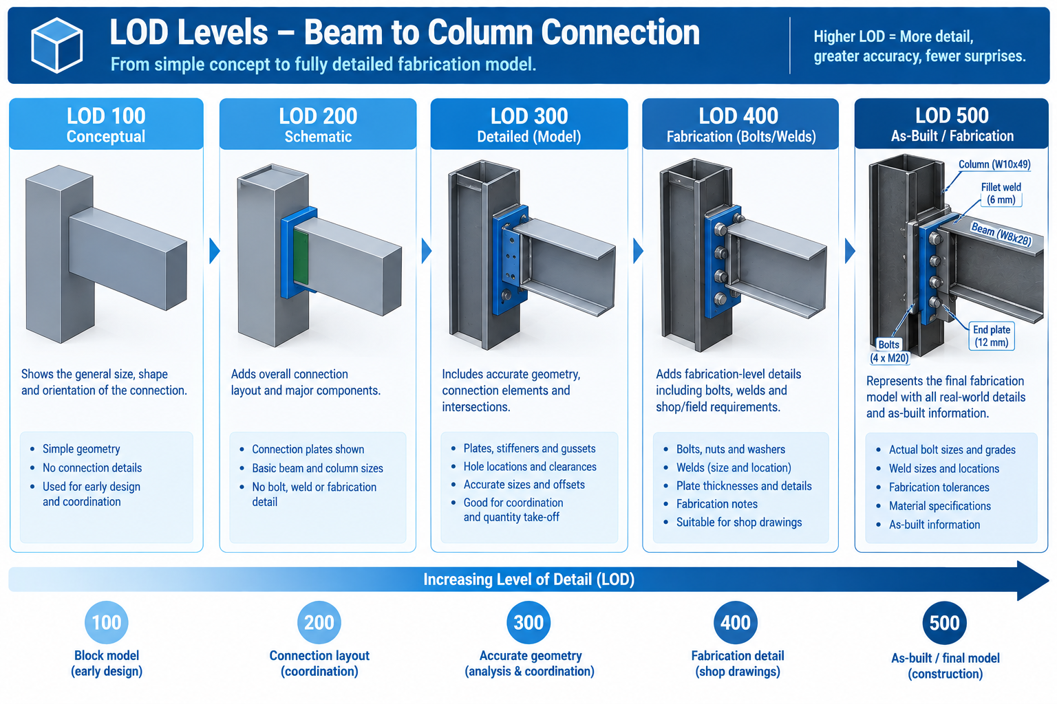
A large project’s workflow has to account for different buildings, zones, or systems sitting at different levels of design maturity on the same calendar date, since phased design and construction is the norm at this scale. Level of Development (LOD) describes how much geometric and data detail a model element carries at a given stage, and it directly determines what coordination check that geometry can meaningfully support.
| LOD | What It Contains | Typical Stage | Coordination Implication |
|---|---|---|---|
| LOD 100 | Conceptual massing, approximate size/shape/location | Concept design | Not suitable for clash detection; visualisation and space planning only |
| LOD 200 | Generalised systems with approximate quantities and orientation | Schematic design | First stage for checking basic, large-scale spatial conflicts |
| LOD 300 | Specific systems accurately sized, shaped, located, oriented | Design development | Formal, recurring clash detection across all disciplines should be fully underway |
| LOD 350 | LOD 300 plus specific interfaces and connections (hangers, supports) | Late DD / early construction docs | Interface-level clashes (support/connection conflicts) become visible |
| LOD 400 | Fabrication-level detail with manufacturer and fabrication info | Construction docs / shop drawings | Must be re-coordinated against the current design model before fabrication starts |
| LOD 500 | As-built, field-verified installed condition | Construction completion / handover | Source of truth for the facilities model; discrepancies from LOD 400 should be captured |
Mixed-LOD Coordination: The Reality on Large Phased Projects
A single coordination cycle may need to test an early-design Phase 3 building at LOD 200 against an under-construction Phase 1 building at LOD 400, particularly at shared interfaces like a connecting bridge or a common below-grade structure. This mixed-LOD condition is normal on large projects and needs explicit planning: for each interface between phases at different LOD, define which elements are fixed (adjacent phase already under construction) and which are still flexible.
The Common Data Environment Workflow
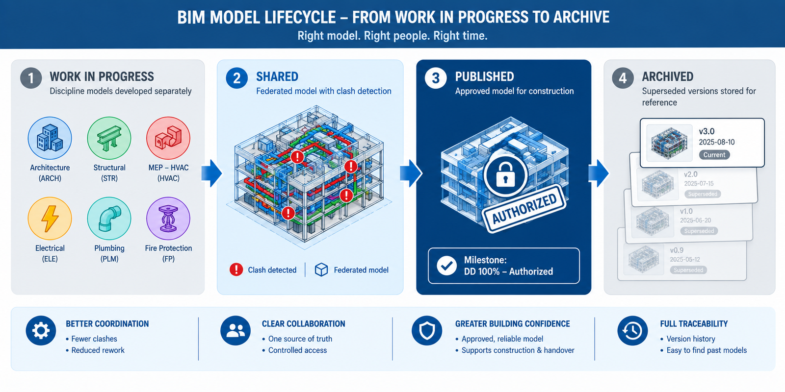
The common data environment (CDE), formalised internationally through the ISO 19650 series, is the information management structure that makes reliable coordination possible once a project has more participants than can informally track each other’s model versions through email and shared drives. The CDE defines four states every model version passes through.
| CDE State | Purpose | What Moves It Forward | Common Pitfall |
|---|---|---|---|
| Work in Progress (WIP) | Where each discipline develops and iterates privately before sharing | Internal quality check and discipline lead approval | Sharing WIP-quality models directly, bypassing the quality check |
| Shared | Where models are federated and coordinated against each other; clash detection happens here | Outstanding critical clashes resolved; model authorised for formal issue | Treating Shared as final and proceeding to construction from an unauthorised version |
| Published | The formal, authorised milestone version used for issue, approval, and contractual purposes | A new milestone is reached and a superseding version is published | Continuing to reference a Published version after a newer one supersedes it |
| Archived | A permanent, immutable record of every previously Published version | Not applicable; retained for reference | Failing to retain a complete history, losing the ability to trace a decision later |
The Publish Gate: The Step That Would Have Prevented the Campus Corridor Failure
The single workflow element most directly responsible for preventing a failure like the campus utility corridor breakdown is the formal gate between Shared and Published states. This is the point where the coordination team confirms a model version has been reviewed, critical clashes are resolved, and the version is authorised as the official reference for every downstream party. Without an enforced publish gate, every organisation independently judges which version is current, exactly the condition that produced three subcontractors working from three unreconciled corridor models.
Implementing the gate well requires more than software; it requires an agreed governance procedure specifying who has authority to publish, what review must be completed first, and how participants are notified when a new version supersedes the last. This is typically documented in the BIM execution plan and owned by the information manager.
Worked Examples
A multi-terminal airport expansion: An international airport expansion added a new terminal, a connecting people-mover system, and renovations to two operational terminals, coordinated across 34 firms over seven years. Early coordination attempts, using the same informal single-coordinator approach that had worked on smaller projects, fell behind within the first year, with clash reports taking over three weeks since the coordinator was manually federating models from five different native platforms with no shared CDE.
The project introduced a formal ISO 19650-aligned CDE with a dedicated information manager, split coordination into four parallel tracks (new terminal, people-mover, Terminal A, Terminal B), each with discipline BIM coordinators reporting to a project BIM manager, and defined an explicit interface register for connections between the new terminal and the existing operational terminals.
Clash report turnaround dropped from three weeks to five days once models were federated from a governed CDE, and the interface register caught a fire life-safety systems conflict between the new terminal’s smoke control system and Terminal A’s existing system nine months before it would otherwise have surfaced during commissioning, a stage where the conflict on an operational, occupied terminal would have carried substantially higher risk.
Read more on this article: How BIM Prevents Construction Delays: Six Causes and Their Fixes
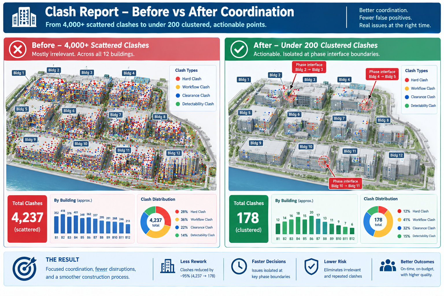
A mixed-use residential and retail campus: A twelve-building campus was designed and built in four overlapping phases over five years, sharing a common below-grade parking structure and central utility infrastructure. By year three, Phase 1 was at LOD 500 (as-built), Phase 2 under construction at LOD 400, Phase 3 in construction documentation at LOD 350, and Phase 4 still in schematic design at LOD 200, all sharing the same infrastructure.
Early attempts ran a single, uniform clash test across all twelve buildings together, producing an unmanageable mixed-LOD report where genuine Phase 3/Phase 4 interface conflicts were buried among thousands of low-value results from comparing precise LOD 400 geometry against approximate LOD 200 massing.
The team restructured the clash matrix to test each phase against itself at full detail, plus a separate, explicitly scoped interface-only test at each phase boundary, limited to the specific shared elements crossing between phases. This cut the weekly clash report from over 4,000 largely irrelevant results to under 200 genuinely actionable ones, and the interface-only tests caught a below-grade utility riser conflict between Phase 3 and Phase 4 while Phase 4 was still in schematic design, cheap enough to resolve with a routing change on paper.
Frequently Asked Questions
At what project size does a formal CDE and role structure become necessary?
There’s no fixed threshold, but the practical signal is when informal coordination starts producing version-confusion failures. Most projects with more than 8-10 firms, concurrent design and construction phases, or a schedule over two years benefit from a formal CDE and defined roles, even in a lighter-weight form.
Does ISO 19650 have to be formally adopted to get the benefit of a CDE workflow?
No. ISO 19650 gives a well-tested structure and vocabulary, but a project can implement the same underlying workflow, a governed staging process with a publish gate and version control, without formally certifying compliance. Adopt it informally if it solves the coordination problem; engage a qualified advisor only if a contract requires certified compliance.
How should a large project handle disciplines working at different LOD levels?
This is normal, not a problem to eliminate. Don’t force every discipline to the same LOD artificially. Instead, define for each interface between different-LOD zones which elements need general spatial checking versus precise geometric checking that requires both sides at LOD 300 or higher.
Who should own the BIM execution plan on a large, multi-stakeholder project?
Typically the owner’s project team or a designated lead consultant acting on the owner’s behalf, since the plan needs authority across every participating firm, which no single design firm or contractor can enforce over the others. Very large projects often engage an independent BIM management consultant for this role.
Why do large project coordination workflows break down even after being properly set up?
Usually because the workflow is documented at kickoff but not actively maintained as the participant list, phases, and staff change over a multi-year duration. A correct publish gate and role structure can degrade silently as new firms join without onboarding or as shortcuts creep back in under schedule pressure. Audit and reinforce the workflow at defined milestones, not just once at setup.
Key Takeaways
The campus utility corridor failure, and the airport and mixed-use campus examples, share a common lesson: on a large project, the coordination methods themselves are only as reliable as the workflow governing who’s working from which model version, at what stage, reporting to whom, and authorised by what gate. None of these failures happened because a discipline modelled something incorrectly within their own scope. Each happened because the structure connecting dozens of independently working organisations had a gap.
This is why large project coordination can’t simply be the same informal process used on a small project, scaled up by adding more people. It needs the explicit role structure, LOD-aware test planning, and governed CDE workflow set out here, built in from the earliest stages of the BIM execution plan and actively maintained through a duration that can span most of a decade.
The projects that get this right don’t have fewer moving parts than the ones that struggle; a twelve-building, five-year, multi-phase campus carries the same underlying complexity regardless of coordination quality. What differs is whether that complexity is managed through a defined, governed workflow that catches version confusion and interface conflicts before they reach the field, or discovered the way the campus utility corridor conflict was: three subcontractors quietly working from three different answers to the same question, until someone finally asked which one was right.