A property management company recently acquired a commercial office building. The previous owner handed over a set of architectural drawings from the original 1998 construction. Within six months, the new FM team needed to reconfigure an HVAC zone to accommodate a tenant fit-out. The drawings showed ductwork in one configuration. What was actually in the ceiling was something else entirely: two decades of undocumented modifications, rerouted runs, and added dampers that had never been captured in any drawing.
The tenant fit-out that should have taken four weeks took eleven. Three change orders were issued because contractors kept encountering conditions that contradicted the available documentation. The additional cost: just under $40,000. The root cause: no accurate as-built drawings.
This scenario is not unusual. It plays out in commercial buildings, industrial facilities, infrastructure projects, and residential developments around the world, every time a building changes hands, undergoes renovation, requires maintenance, or faces a regulatory inspection. The absence of accurate as-built drawings is one of the most consistently expensive and most consistently preventable problems in the built environment.
This guide explains what as-built drawings are, how they differ from related document types, who is responsible for producing them, what the legal and contractual requirements look like, how modern technology is changing the way they are created, and what happens when they are missing, incomplete, or inaccurate. Whether you are a building owner, facility manager, contractor, architect, or project manager, this is the foundational knowledge that protects you across the full lifecycle of a built asset.

1. What Are As-Built Drawings? A Clear Definition
As-built drawings, also called as-builts, record drawings, or as-constructed drawings, are a revised set of engineering and architectural drawings submitted at project completion that reflect how a structure was actually built, not how it was originally designed.
Every construction project begins with design drawings that represent the architect’s and engineer’s intent. These drawings are issued for permit, tendered against, and used to guide construction. But construction is not a perfect translation of design intent into physical reality. Materials get substituted, site conditions require routing changes, coordination issues move equipment, dimensions are adjusted in the field, and change orders modify the original scope. The gap between what was designed and what was built is not a failure of the construction process. It is a natural and expected consequence of building in the real world.
As-built drawings close that gap. They are the official, verified record of what was actually constructed: the exact dimensions, locations, elevations, routing, materials, and specifications of every element of the completed work. They become the authoritative technical reference for the building or structure for every purpose that comes after construction, whether that is routine maintenance, emergency repair, tenant fit-out, major renovation, asset sale, or regulatory inspection.
| KEY POINT: The core definition. As-built drawings are the final, verified record of a construction project as it was actually built. They incorporate all field changes, substitutions, and deviations from the original design drawings, creating an accurate technical baseline for the building’s entire operational life. |
The Construction Management Association of America (CMAA) defines as-builts as: a revised set of drawings submitted by a contractor upon completion of a project that reflects all changes made in the specifications and working drawings during the construction process, and shows the exact dimensions, geometry and location of all elements of the work completed under the contract.
That definition is precise and important. As-builts show the exact dimensions and location of all elements. Not approximate. Not mostly accurate. Exact, within the tolerances of the measurement methods used. This precision standard is what distinguishes a proper as-built drawing set from a lightly annotated copy of the original design drawings.
2. As-Built vs. Record Drawings vs. Shop Drawings: The Differences That Matter
These three document types are frequently confused, sometimes used interchangeably, and occasionally conflated in contracts in ways that create expensive disputes. Understanding the precise distinction between them is essential for anyone involved in construction documentation.
| Document Type | Who Produces It | When Produced | What It Shows | Legal Status |
|---|---|---|---|---|
| Design / Construction Drawings | Architect or engineer of record | Before construction begins | Design intent: what is planned to be built | Basis for permit approval; contract document |
| Shop Drawings | Contractor or subcontractor | Before installation of a specific element | How the contractor plans to build or install something; fabrication details | Submitted for architect/engineer review and approval |
| As-Built Drawings | Contractor (GC and subs), verified by architect/engineer | During and after construction | What was actually built: all field changes, deviations, and substitutions from design | Part of project closeout package; often contractually required |
| Record Drawings | Architect or engineer of record | After construction, based on as-built markups submitted by contractor | Architect’s or engineer’s final updated set incorporating confirmed field changes | More formally verified than contractor as-builts; sometimes required for permit closeout |
| Measured / Survey Drawings | Specialist surveyor or scan-to-CAD firm | After construction or at any point during building’s life | Conditions as they exist, verified by physical measurement or laser scan | Independently verified; highest accuracy standard |
The distinction between as-built drawings and record drawings deserves particular attention because the two terms are often used interchangeably but carry different implications of accuracy and responsibility.
As-built drawings: Produced by the contractor, based on field markups maintained during construction. They represent the contractor’s record of what was built. They are subject to the quality and diligence of whoever maintained the site markups. Accuracy varies significantly across projects and contractors.
Record drawings: Produced by the architect or engineer of record, incorporating the contractor’s as-built markups after verification. They carry the design professional’s stamp and represent a higher standard of accuracy and professional accountability than contractor as-builts alone.
Measured or survey drawings: Produced by independent measurement, either traditional survey methods or modern laser scanning. They are verified against the physical structure, not just against markup documentation. They represent the highest accuracy standard and are increasingly used where absolute dimensional accuracy is required, such as for heritage buildings, complex renovations, or high-precision facility management.
| INSIGHT: Specify the document type in your contract. Construction contracts that specify ‘as-built drawings’ without defining the standard of accuracy or whether record drawings (architect-verified) are required frequently produce disputes at closeout. Be explicit: specify who produces the drawings, at what standard, and who verifies them. |
3. Why As-Built Drawings Matter After Construction Is Complete
The case for as-built drawings is sometimes framed as a documentation compliance requirement, something to produce at project closeout because the contract or the AHJ (authority having jurisdiction) requires it. This framing undersells the actual value by a significant margin. As-built drawings are not a paperwork obligation. They are the foundational technical document for everything that happens to a building after the construction team leaves.
Facility Operations and Maintenance
Facility management teams make decisions daily about building systems based on what the documentation tells them is there. Where are the main water shutoffs? Which electrical circuit feeds which zone? Where does the HVAC trunk line run before it splits into branch ducts? How deep is the gas main below the parking lot surface?
When as-built drawings are accurate, maintenance technicians can answer these questions from a drawing, plan their work, order the right parts, and complete the job without surprises. When as-builts are missing or inaccurate, the answers are discovered empirically, often by opening walls, cutting into ceilings, or digging up slabs. That discovery process is expensive, disruptive, and sometimes dangerous.
As the Matterport as-built documentation research notes, accurate records allow facility management teams to rapidly diagnose and resolve maintenance issues. When a maintenance issue arises related to supply grilles that were relocated during construction but never updated in the drawings, the FM team searching for them in the wrong location loses hours. Across a large portfolio, undocumented changes accumulate into a significant hidden operational cost.
Renovation and Tenant Fit-Out
Every renovation project begins with a question: what is behind this wall, above this ceiling, and under this floor? For structural renovations, the answer determines whether a wall can be removed. For MEP modifications, it determines how new systems connect to existing infrastructure. For tenant fit-outs, it determines construction cost, timeline, and the potential for change orders.
When renovation designers work from accurate as-builts, they can develop designs that account for actual conditions. When they work from outdated or inaccurate documentation, they discover reality during construction, in the form of change orders, schedule delays, and contractor disputes. Published research consistently cites rework as accounting for 12 to 15 percent of construction costs on a typical project. A meaningful portion of that rework is attributable to designs developed without accurate as-built information.
| DATA: Rework cost impact. On a typical construction project, rework accounts for 12 to 15 percent of total construction cost. With accurate as-built documentation enabling better preconstruction planning, laser scanning data shows rework rates can be reduced to 1 to 3 percent (GP Radar laser scanning research). |
Asset Sales and Due Diligence
Commercial property transactions involve extensive due diligence on the physical condition and documentation of the building. Buyers, their lenders, and their technical advisors will request as-built drawings as part of the documentation package. Missing or incomplete as-builts are a red flag that increases buyer perceived risk, which translates directly into price pressure or deal conditions.
More practically, a property transaction that closes without complete as-built documentation transfers the risk of undocumented conditions to the new owner. If concealed systems require emergency repair, the new owner has no baseline documentation against which to understand what was original construction and what was a previous modification. The cost of reconstructing accurate documentation after the fact is substantially higher than producing it at construction closeout.
Legal and Dispute Resolution
Construction disputes frequently involve questions about what was actually built versus what was contracted, designed, or specified. As-built drawings are the primary evidentiary record for resolving those questions. A contractor who can demonstrate that a deviation from the design was documented, approved, and incorporated into the as-built set is in a fundamentally different legal position than one relying on verbal accounts of field decisions made three years earlier.
From the Law Insider contract clause analysis of as-built requirements: the standard contract clause requires contractors to provide accurate, updated drawings reflecting the completed project, specifically to ensure that the owner receives a clear record of the finished work, facilitating future maintenance, renovations, or audits. When as-builts are missing or disputed, the cost of reconstruction or litigation can exceed the cost of having produced them properly at project completion by an order of magnitude.
Regulatory Compliance and Inspections
In many jurisdictions, as-built drawings are required for occupancy certification, permit closeout, or ongoing regulatory compliance. Facilities subject to fire safety regulations, building codes, environmental permits, or health and safety standards may face inspection requirements where as-built documentation must be produced on demand. An organization that cannot produce accurate as-builts when required by the authority having jurisdiction faces permit violations, occupancy restrictions, or mandatory remediation costs.
In the UK, the Building Safety Act 2022 introduced what practitioners call the Golden Thread: a requirement for buildings above a certain height to maintain a continuously updated digital record of the building, its systems, and all changes made throughout its lifecycle. As-built documentation is the foundation of that Golden Thread. Failure to maintain it is not an administrative shortcoming; it is a legal liability.
4. What As-Built Drawings Must Include: The Complete Content Checklist
A complete as-built drawing set for a construction project is not simply the original drawing set with a few annotations. It is a comprehensive documentation package that covers every system and element of the completed construction. The specific content requirements vary by project type and jurisdiction, but the following checklist represents the standard for a complete commercial or institutional building as-built package.
Architectural As-Builts
- Floor plans with all verified dimensions, room boundaries, and partition locations as constructed
- Ceiling plans showing finished ceiling heights, ceiling types, and locations of access panels
- Elevations (exterior and interior) reflecting final materials, window and door locations, and surface finishes as installed
- Building sections at all critical conditions, updated to reflect as-constructed structural and architectural relationships
- Detail drawings updated to reflect any substituted materials, modified connection details, or site-adjusted dimensions
- Door and window schedules updated to reflect any substitutions or field changes
- Finish schedules updated to reflect material substitutions approved during construction
Structural As-Builts
- Foundation plans with verified pile or footing locations, dimensions, and depths
- Structural floor and roof framing plans with member sizes, spans, and connection types as constructed
- Updated sections at all critical structural conditions
- Any field-modified connection details or member substitutions
- Embedded item locations (anchor bolts, embedded plates, sleeves) verified by measurement
Mechanical, Electrical, and Plumbing (MEP) As-Builts
- HVAC ductwork routing plans updated to reflect all field changes, rerouting, and added components
- Plumbing piping plans with all pipe sizes, routing, valve locations, cleanout locations, and invert elevations
- Electrical single-line diagrams updated to reflect all circuit modifications, panel configurations, and load changes
- Electrical conduit routing plans showing as-installed conduit runs, especially for concealed work
- Mechanical equipment schedules updated to reflect actual installed equipment model numbers, capacities, and locations
- Fire protection (sprinkler) plans updated to reflect all field-adjusted head locations and pipe routing
- Low-voltage systems (data, security, audio-visual) routing and termination documentation
Civil and Site As-Builts
- Site plan updated to reflect actual building footprint, finished grades, and paved area dimensions
- Utility plans showing all installed utility routes, invert elevations, manhole locations, and connection points
- Storm drainage as-builts with pipe sizes, invert elevations, and outfall locations
- Grading plan updated to reflect finished grade contours and drainage patterns as constructed
| INSIGHT: The MEP as-builts are the most critical and most frequently incomplete. MEP systems are the primary reason as-builts matter for facility management. Routing of concealed ductwork, piping, and conduit is impossible to reconstruct without as-built documentation. Yet MEP as-builts are also the drawings most frequently produced from memory or estimate rather than actual field measurement. Require field-verified MEP routing in your contract. |
5. Who Is Responsible for As-Built Drawings?
Responsibility for as-built drawings is one of the most frequently disputed questions in construction closeout, and the answer is less straightforward than most owners expect. Multiple parties have roles, and the consequences of unclear contract language about those roles play out as delayed project closeout, incomplete documentation packages, and disputes over final payment.
The General Contractor’s Role
In most contracts, the general contractor is the party primarily responsible for maintaining as-built markups throughout construction and producing the as-built drawing package at closeout. The GC maintains a set of construction drawings on-site that are updated continuously as field changes occur: each substituted material is noted, each rerouted pipe is marked, each dimension that was adjusted in the field is corrected.
The quality of this process varies enormously across projects and contractors. A disciplined GC with a strong site superintendent who maintains real-time redline markups will produce as-builts that are genuinely accurate. A GC who defers all markup documentation until the last week before closeout, relying on memory and subcontractor records, will produce as-builts that are incomplete, approximate, and unreliable.
Subcontractor Contributions
Individual trades maintain their own as-built markups for their scope of work. The mechanical contractor tracks all ductwork routing changes. The electrical contractor maintains updated single-line diagrams and conduit routing plans. The plumbing contractor documents all pipe routing deviations and invert elevation changes. These subcontractor markups feed into the GC’s master as-built package.
The coordination of subcontractor as-built documentation is a GC management responsibility. When subcontractors submit their closeout packages late, incompletely, or in incompatible formats, the GC’s as-built package suffers. Contracts should require subcontractors to maintain as-built markups throughout their work and submit them in a defined format and timeline.
The Architect’s and Engineer’s Role
The architect and engineers of record have a role in reviewing and verifying the contractor’s as-built markups, and in some contracts, in producing formally updated record drawings that incorporate the verified field changes. This is an important distinction: contractor as-builts and architect-produced record drawings carry different levels of professional accountability and are not interchangeable in regulated environments.
As the LiDAR As-Built Drawings analysis of responsibility notes: on existing buildings, responsibility typically falls on the building owner or whoever is commissioning documentation for a renovation, permit, or facility management purpose. When as-builts are needed retroactively with verified accuracy, owners and project managers increasingly hire a third-party as-built documentation provider, removing the ambiguity entirely.
The Owner’s Role and Responsibility
Owners bear responsibility for two things that directly affect as-built quality. First, contract language: owners who do not require as-built drawings in their contracts, or who specify them vaguely, should not be surprised when they receive incomplete or inaccurate documentation at closeout. Second, project management: owners who allow final payment to be released before as-built documentation has been reviewed and accepted have lost their primary leverage for ensuring quality documentation.
| WATCH OUT: Do not release final payment or retainage until as-builts are accepted. Final payment and retainage release are the primary contractual levers for ensuring complete as-built documentation. Once a contractor has received full payment and demobilized, the incentive to produce or correct as-built documentation is dramatically reduced. Review and accept the as-built package before releasing final payment. |
6. Legal and Contractual Requirements: What Owners and Contractors Must Know
The legal and regulatory landscape for as-built drawings is genuinely complex because it varies by jurisdiction, project type, contract form, and applicable regulatory framework. The practical answer to ‘are as-built drawings legally required?’ is: sometimes yes by regulation, almost always yes by contract, and invariably yes by the practical needs of operating and maintaining the built asset.
Regulatory Requirements
In many jurisdictions, submitting as-built documentation is a condition of final occupancy certification or building permit closeout. The authority having jurisdiction (AHJ), typically a municipal building department, fire marshal, or combination thereof, may require as-built drawings demonstrating that what was built matches what was permitted, or that approved deviations from the permitted design have been documented.
For public works projects (roads, utilities, government buildings), as-built documentation requirements are almost universally mandatory and are often specified in the project contract with public agencies. Municipal water and sewer utilities typically require as-built utility plans for all new infrastructure before accepting the system into their maintenance responsibilities.
In the UK, the Building Safety Act 2022 established the Golden Thread requirement for higher-risk buildings: a continuously updated digital record of the building, its structural and fire safety systems, and all changes made throughout the building’s life. As-built documentation is the origin point of that Golden Thread. Similar requirements are emerging in other jurisdictions under various names.
Contractual Requirements
Even where regulation does not mandate as-built drawings, standard construction contracts almost universally require them. The AIA A201 General Conditions of the Contract for Construction, one of the most widely used contract forms in US commercial construction, requires the contractor to prepare as-built drawings and submit them to the architect as a condition of project closeout.
The contract requirements to look for and define clearly include:
- Format: Are as-builts required as marked-up paper copies, AutoCAD DWG files, Revit models, PDFs, or some combination? Specifying ‘as-built drawings’ without defining the deliverable format produces disputes about what constitutes compliance.
- Who produces them: Contractor as-builts, architect-produced record drawings, or independently verified survey drawings? Each has different accuracy implications.
- Who verifies them: Does the architect or engineer of record review and sign off on the as-built package before it is accepted? This verification step is critical for accountability and accuracy.
- Timing: When must as-builts be submitted relative to substantial completion, final completion, and final payment? Requiring submission at substantial completion rather than final completion provides a review window before the contractor fully demobilizes.
- Standards compliance: Must as-builts comply with a specific drawing standard (NCS, AIA layer guidelines, client-specific standards)?
| IN PRACTICE: Contractual protection. The Law Insider analysis of as-built contract clauses confirms that the standard clause requires the contractor to provide as-builts immediately following completion and approval of the facilities, with final payment conditioned on receipt of an acceptable documentation package. Owners who do not have this language in their contracts should add it. |
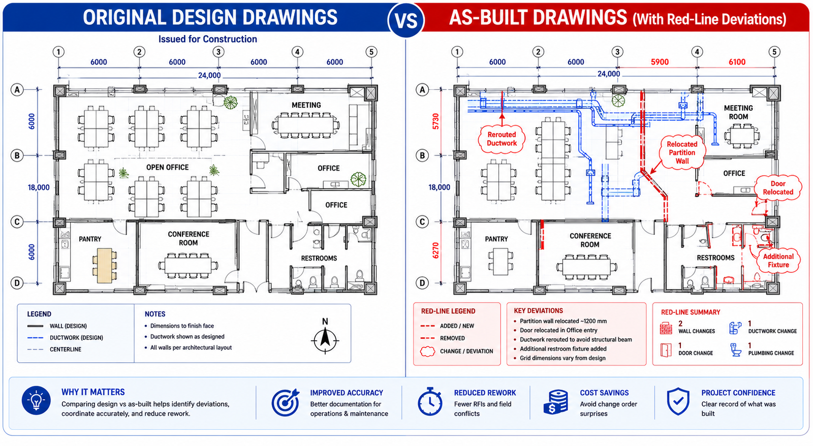
7. How As-Built Drawings Are Created: From Red-Lines to Laser Scanning
The method used to produce as-built drawings has a direct impact on their accuracy, the time and cost of production, and their usefulness for downstream applications. In 2026, the industry is in active transition from manual red-line methods to digital documentation workflows, and the difference in output quality is significant.
Method 1: Manual Red-Line Markups
The traditional as-built documentation method is the red-line markup: the site superintendent or project engineer maintains a set of printed construction drawings on-site and marks up changes in red pen as they occur. At project completion, these marked-up drawings are scanned and submitted, or the markups are transferred to CAD files by a drafter.
This method is inexpensive and requires no special technology. Its limitations are significant. It relies entirely on the discipline of the site team in recording changes as they occur. Changes that are not recorded immediately are often forgotten or reconstructed from memory at closeout. The accuracy of hand-measured field dimensions is limited by the care taken with the tape measure, and concealed systems (pipes buried in slabs, conduit above finished ceilings) cannot be verified after construction without destructive access.
Method 2: CAD Drafting from Field Notes
An improved version of the manual approach involves a dedicated drafter, either internal or from an engineering design service, creating updated CAD drawings from the site superintendent’s field notes, sketches, and redline markups. This produces cleaner, more legible as-built drawings than raw redline scans, but inherits all the accuracy limitations of the underlying field records.
For most standard commercial construction projects, this remains the most common as-built production method. It produces documents that are adequate for facility management purposes when the field records are complete and the drafter is experienced. It is not adequate for high-precision applications or for buildings with complex MEP systems where routing accuracy is critical.
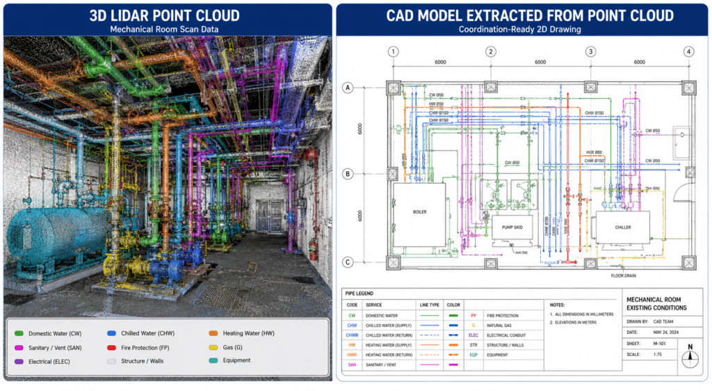
Method 3: 3D Laser Scanning (LiDAR)
Laser scanning has transformed as-built documentation in the past decade, and in 2026 it is rapidly becoming the standard of care for commercial and institutional projects where accuracy matters. A LiDAR scanner fires millions of laser pulses per second, measures the return time of each pulse with sub-millimeter precision, and builds a complete three-dimensional point cloud of the scanned space, capturing every visible surface in the scan environment.
That point cloud can then be used to produce as-built drawings in AutoCAD or Revit with tolerances of plus or minus 3 to 5 millimeters, significantly more accurate than manual measurement methods, and capable of capturing geometry that would be impossible to measure manually (complex ceiling structures, curved surfaces, multi-level spatial relationships).
| DATA: Laser scanning time savings. What used to take weeks of manual field measuring takes days with 3D laser scanning. Large sites that previously required weeks of survey time can be scanned in hours, with higher accuracy and without access to concealed systems after construction is complete (LiDAR Precise Plans, 2026 guide). |
Laser scanning limitations: LiDAR scanners capture visible surfaces only. They cannot see inside walls, above solid ceilings, or below concrete slabs. For existing buildings where MEP systems are already concealed, laser scanning documents what is visible. For new construction where scanning occurs before finishes are installed, it can capture far more. The timing of scanning relative to construction progress is therefore important in maximizing scan coverage.
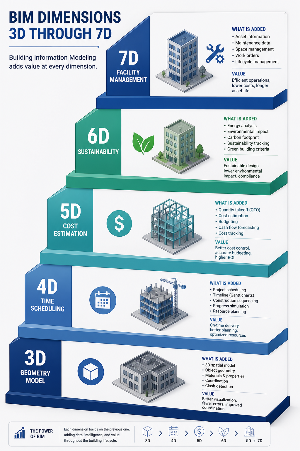
Method 4: Scan-to-BIM
The highest-value as-built documentation method for complex buildings is Scan-to-BIM: using laser scan point cloud data as the geometric basis for building an accurate Revit or other BIM model of the as-built conditions. The resulting BIM model is not just a set of drawings. It is a data-rich, three-dimensional representation of the building that can be used for facility management, energy modeling, renovation design, and digital twin development.
Scan-to-BIM workflows are more time and cost-intensive than traditional as-built drafting, but they produce a documentation asset that delivers value over the full lifecycle of the building. The iScano 2026 as-built documentation best practices guide captures the direction the industry is moving: 2026 best practices demand a continuous digital representation of the asset, not just a static PDF.
8. The True Cost of Missing or Inaccurate As-Built Drawings
The cost of not having accurate as-built drawings rarely appears as a line item in any budget. It accumulates across years of building operation in the form of extended maintenance times, change orders on renovation projects, permit submission failures, and dispute costs. Understanding the full cost picture makes the investment in quality as-built documentation easy to justify.
| Scenario | Typical Cost of Inaccurate As-Builts | How It Arises |
|---|---|---|
| MEP renovation or fit-out | $10,000 – $150,000+ in change orders per project | Designers specify work based on documented routing; contractors encounter actual conditions; change orders resolve the gap |
| Emergency MEP repair | Additional 4-12 hours of investigation per incident | Maintenance teams cannot locate shutoffs, routing paths, or connection points without accurate documentation |
| Permit submission failure | 2-6 week delay plus resubmission cost | AHJ rejects permit because submitted drawings do not match actual conditions as visible during inspection |
| Property transaction due diligence | $15,000 – $50,000 in retroactive documentation | Buyer requires accurate as-builts; seller must commission retroactive documentation or accept price reduction |
| Regulatory compliance failure | Variable; potentially significant for regulated facilities | Inability to demonstrate that built conditions match permitted or approved design |
| Structural renovation conflicts | $20,000 – $200,000+ depending on scale | Structural modifications designed without accurate knowledge of existing conditions require costly field adjustment |
| Legal dispute | $50,000 – $500,000+ in legal and reconstruction costs | Inability to establish what was actually built becomes central to construction defect or workmanship dispute |
The construction industry data on rework is instructive here. Research from GP Radar’s laser scanning analysis finds that on a typical construction project, rework accounts for 12 to 15 percent of construction costs, and that the ability to catch conflicts before they happen through accurate as-built and scan data can reduce rework rates to 1 to 3 percent. The mechanism is the same whether the conflict is in new construction or renovation: working from accurate documentation prevents the expensive discovery of reality during construction.
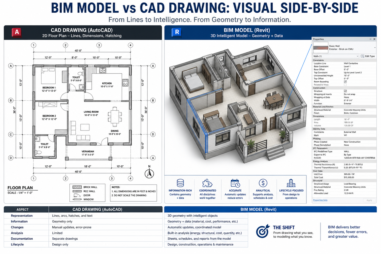
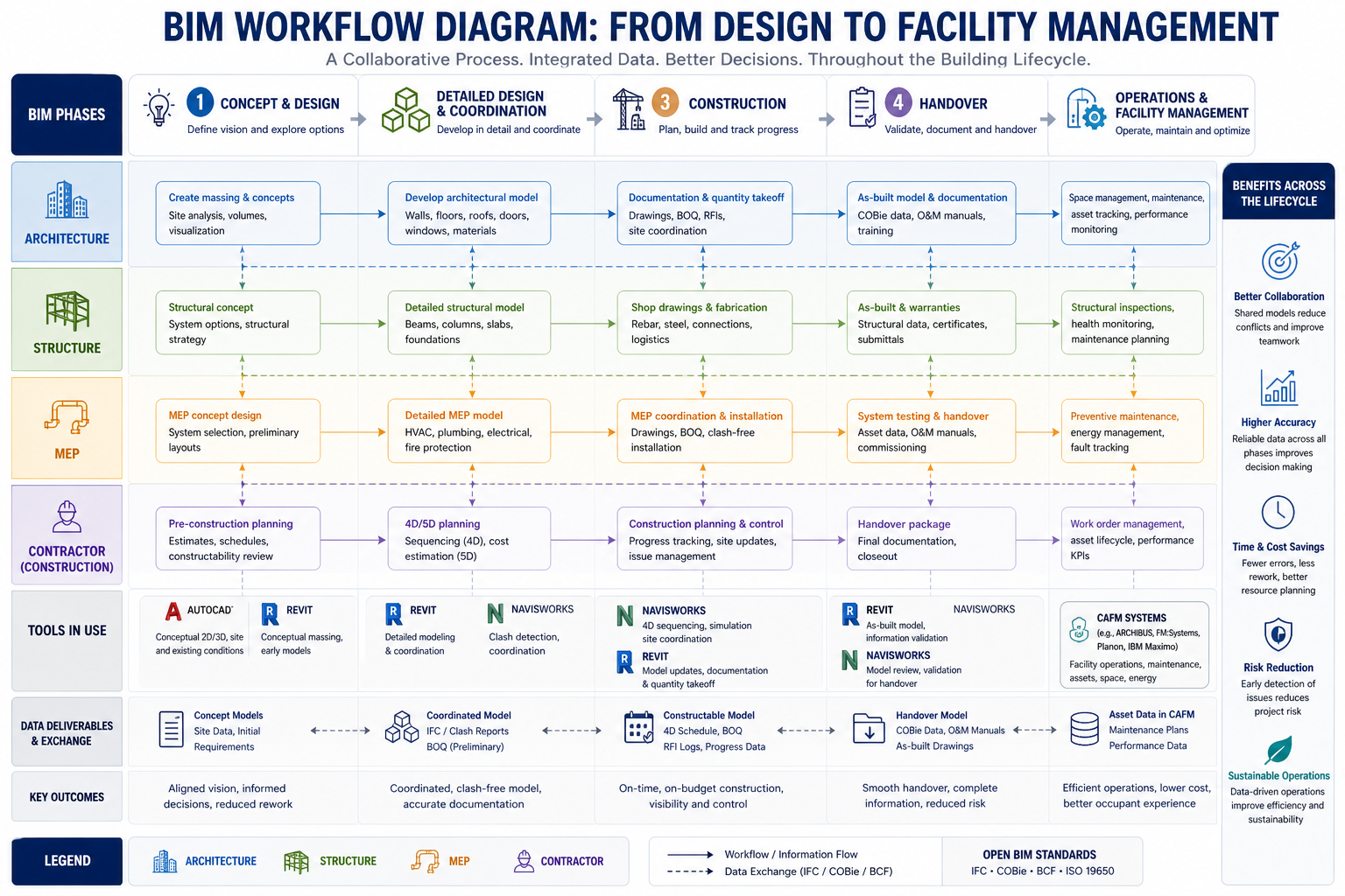
9. As-Built Drawings in the Digital Age: BIM, Scan-to-CAD, and the Golden Thread
The as-built drawing is evolving from a static PDF deliverable produced at project closeout into a living digital record that is continuously maintained throughout a building’s life. This shift is driven by technology, by regulation (particularly the UK Building Safety Act’s Golden Thread requirements), and by the increasing sophistication of facility management and asset management practices.
BIM as the As-Built Platform
Building Information Modeling is transforming what as-built documentation can be. A BIM model is not just geometry. It is geometry with embedded data: material specifications, equipment manufacturer and model numbers, maintenance intervals, warranty information, spatial relationships between systems, and links to external documents. When this model reflects as-built conditions, it becomes a facility management asset of significant value.
Owners who invest in Scan-to-BIM as-built documentation at project handover receive more than a set of drawings. They receive a queryable, three-dimensional record of their building that their FM teams can use for maintenance planning, space management, energy modeling, and renovation design throughout the building’s operational life.
The Digital Twin Connection
As-built BIM models are the foundation for digital twins: continuously updated virtual representations of physical assets connected to real-time sensor data. For commercial buildings, a digital twin built on an accurate as-built BIM model enables predictive maintenance, energy optimization, occupancy management, and safety monitoring. The Matterport as-built documentation analysis notes that digital twins ensure as-builts are always updated when changes are made to buildings, creating a continuous documentation loop that eliminates the historical problem of documentation drifting out of accuracy with the physical asset over time.
The Golden Thread: Regulatory Driver for Digital As-Builts
The UK Building Safety Act 2022 introduced the Golden Thread concept as a legal requirement for higher-risk buildings: a single, accessible, continuously updated digital record of the building and all changes made to it throughout its lifecycle. As-built documentation is the starting point and the foundation for Golden Thread compliance.
The implications extend beyond UK regulation. The Golden Thread concept reflects a broader industry direction: buildings increasingly need continuously maintained digital records, not just static documentation packages produced at construction completion. Organizations that invest in high-quality digital as-built documentation today are building the infrastructure for whatever regulatory and operational requirements emerge over the next decade.
AI and the Future of As-Built Documentation
Emerging AI capabilities are beginning to accelerate as-built documentation workflows. AI-powered tools can extract dimensions and annotations from point cloud data, auto-generate drawing sheets from BIM models, identify discrepancies between design drawings and scan data, and flag potential documentation gaps. While these capabilities are still maturing in 2026, the trajectory is clear: as-built documentation that once required weeks of manual drafting will increasingly be produced in hours through AI-assisted scan-to-drawing workflows.
10. Best Practices for As-Built Documentation
Whether you are an owner, a general contractor, a project manager, or a facility professional, the following practices consistently distinguish organizations that manage as-built documentation well from those that struggle with incomplete or inaccurate records.
For Owners and Project Managers
- Specify as-built requirements in the contract before executionDefine the deliverable format (CAD, BIM, PDF), who produces it, who verifies it, the accuracy standard required, and the submission timeline relative to substantial and final completion. Vague contract language produces vague documentation.
- Require progressive documentation, not end-of-project dumpsRequire the GC to maintain current redline markups throughout construction and submit interim as-built updates at defined milestones. End-of-project reconstruction of field changes from memory is the primary cause of as-built inaccuracy.
- Link final payment to as-built acceptanceDo not release retainage or final payment until the as-built documentation package has been reviewed, found complete, and formally accepted. This is the primary contractual lever available to owners and it is consistently under-used.
- Consider laser scanning for MEP-intensive facilitiesFor buildings with complex mechanical, electrical, or plumbing systems where routing accuracy is critical for future operations, a LiDAR laser scan at practical completion, before ceilings and finishes conceal systems, is a cost-effective investment in building lifecycle value.
For General Contractors
- Assign as-built markup responsibility on day oneDesignate a specific person (superintendent, project engineer, or MEP coordinator) responsible for maintaining as-built redlines from the first day of construction. Do not treat this as a closeout activity.
- Require subcontractor as-built submissions as a condition of final subcontract paymentMirror the owner’s leverage with your own subcontractors. Make sub-tier as-built documentation a condition of final payment release at the subcontract level.
- Use digital markup tools where possibleConstruction project management platforms (Procore, Autodesk Construction Cloud, PlanGrid) allow digital redlines to be maintained on mobile devices at the point of work. Digital markups are easier to transfer into final as-built drawings than handwritten notes on paper plans.
- Do not produce as-builts from memory at closeoutThis is the single most common cause of as-built inaccuracy. If field changes were not documented as they occurred, the most honest and defensible path is to commission a survey or scan of the actual conditions rather than reconstruct undocumented changes from recollection.
For Facility Managers and Building Owners
- Audit your existing as-built documentationMost buildings more than ten years old have as-built documentation that is significantly out of date due to accumulated undocumented modifications. Audit your documentation against actual conditions, identify the gaps, and commission updated documentation before the next renovation or system modification project.
- Establish a documentation update protocol for facility modificationsEvery time a system is modified, a partition is relocated, or new MEP infrastructure is added, update the as-built documentation as part of the work scope. The discipline of continuous documentation maintenance prevents the accumulation of undocumented changes that makes documentation unreliable over time.
11. FAQ: As-Built Drawings Answered
What is the difference between as-built drawings and record drawings?
As-built drawings are produced by the contractor and reflect the contractor’s record of field changes made during construction. Record drawings are produced by the architect or engineer of record, incorporating the contractor’s as-built markups after professional review and verification. Record drawings carry the design professional’s stamp and represent a higher standard of accuracy and professional accountability. In practice, the terms are often used interchangeably in contracts, which can create disputes. Specify clearly which document type you require, including the standard of accuracy and who bears professional responsibility for verification.
Are as-built drawings legally required?
The answer depends on jurisdiction, project type, and contract. In many jurisdictions, as-built documentation is required for building permit closeout or occupancy certification. For public works, utility installations, and government buildings, it is almost always contractually and regulatory mandatory. In the UK, the Building Safety Act 2022 requires continuously maintained digital building records (the Golden Thread) for higher-risk buildings. For private commercial projects, as-built documentation is typically required by the construction contract rather than by statute, but the contractual requirement is nearly universal in standard contract forms. The most direct answer is: for any project above a modest scale, you should assume as-built documentation will be required, and plan accordingly.
Who pays for as-built drawings?
The cost of producing contractor as-built markups during construction is typically included in the general contractor’s contract scope. The cost of a drafter converting those markups to final CAD drawings is also typically the GC’s responsibility unless the contract specifies otherwise. Architect-produced record drawings are typically a separately defined service in the architect’s contract, compensated as part of construction administration services. Laser-scanned as-built documentation, when required at a higher accuracy standard than standard contractor as-builts, may be either a GC deliverable (if specified in the contract) or a direct owner-commissioned service from a specialist provider. Retroactive as-built documentation for existing buildings is always an owner cost, typically commissioned from a specialist survey or scan-to-CAD firm.
How accurate do as-built drawings need to be?
The accuracy standard depends on the intended use. For general facility management and renovation design, drawings accurate to plus or minus one inch (25 mm) are typically sufficient. For structural and mechanical system design where clearances and connections are critical, plus or minus one-quarter inch (6 mm) accuracy is the appropriate standard. For high-precision applications such as industrial facilities, clean rooms, or heritage building restoration, the accuracy standard may be plus or minus 3 to 5 millimeters, achievable only through laser scanning. Specifying the accuracy standard in the contract, rather than accepting whatever the contractor delivers, is the way to ensure the documentation is actually usable for its intended purpose.
What happens if as-built drawings are missing for an existing building?
If as-built drawings are missing or substantially out of date for an existing building, the options are: commission a new measured survey using traditional methods (tape measure and total station), commission a laser scan of the building to produce a high-accuracy point cloud that can be drafted to CAD, or reconstruct documentation from available sources (original design drawings, old permit records, maintenance notes, and field inspection) accepting that the resulting drawings will have higher uncertainty than measured documentation. For buildings undergoing significant renovation, a laser scan is almost always the most cost-effective approach because the accuracy it provides reduces the change order risk that inaccurate documentation generates during construction.
How long should as-built drawings be retained?
Retention requirements vary by jurisdiction and project type, but the practical standard for building as-built documentation is: retain for the full operational life of the building plus applicable statutory limitation periods. For commercial buildings, this typically means indefinitely, since buildings have multi-decade operational lives and the documentation becomes more valuable, not less, as the building ages and its original construction team disperses. For regulated facilities (industrial plants with environmental permits, healthcare facilities, defense buildings), consult applicable regulations, which may specify minimum retention periods. The practice of discarding as-built drawings when they seem ‘out of date’ is one of the primary causes of expensive documentation reconstruction projects.
Conclusion: As-Built Drawings Are a Building Asset, Not a Paperwork Obligation
Every building is, in some sense, a documentation project as well as a construction project. The physical structure has a finite life determined by materials, maintenance, and use. The documentation record, if well maintained, can outlast multiple building lifetimes as the accumulated knowledge of what was built, how it was modified, and what decisions were made at each stage of the building’s evolution.
As-built drawings are not a closeout checkbox or a bureaucratic formality. They are the foundational technical document for everything that happens to a built asset after the construction team leaves: every maintenance decision, every renovation design, every regulatory inspection, every property transaction, and every emergency repair. The quality of that documentation determines how quickly, accurately, and cost-effectively all of those activities can be conducted.
The scenario at the opening of this guide, a $40,000 overrun on a tenant fit-out caused by undocumented MEP modifications, is not an unusual story. It is a routine outcome of undocumented construction changes in a building that changed hands without complete as-built documentation. It is also entirely preventable.
Produce complete as-builts. Maintain them through every modification. Make documentation update a standard part of every facility change order scope. And when documentation is missing or out of date for an existing building, invest in accurate reconstruction before the next renovation project reveals the cost of not having it.
Need accurate as-built drawings for your project or facility?
Explore our related guides on version control for engineering drawings, what CAD drafting costs in 2026, how to write a complete RFQ for CAD and drafting services, and the differences between in-house and outsourced CAD drafting to build a complete technical documentation framework for your organization.