Every engineering organization that works with more than one CAD system, sends models to suppliers, receives geometry from customers, or delivers files to manufacturing has faced it: the model looked perfect on screen, left the sender’s system in good shape, and arrived at the destination broken. Missing faces. Open surface gaps. A solid that the receiving system identifies as a surface set. Dimensions that are wrong by a factor of 25.4. GD&T annotations that simply did not make the journey.
CAD data translation problems are not edge cases. They are a routine cost of multi-system engineering work, and the financial impact is significant: engineering hours spent diagnosing and repairing translated geometry, manufacturing errors caused by translation artifacts that escaped detection, simulation failures caused by non-manifold topology, and supplier misunderstandings caused by missing or corrupted PMI data. For teams that regularly exchange CAD data across different platforms, translation quality is a measurable contributor to project cost and schedule that deserves the same engineering discipline applied to any other technical workflow.
The reason translation problems persist despite decades of standardization effort is not that the formats are poorly designed. STEP, in its AP242 implementation, is a technically sophisticated standard capable of carrying full solid geometry, assembly structure, product manufacturing information, and composite material definitions. The problem is the gap between what the format is capable of carrying and what any given CAD system’s translator actually exports and imports correctly. That gap varies by platform version, by the complexity of the geometry, by the specific entities in the model, and by the translator configuration settings that most users never examine.
This article closes that knowledge gap. It covers what each major format can and cannot carry, what causes each of the common translation error types at a technical level, how to detect errors before they cause downstream damage, how to fix them when they occur, and how to prevent them at the source by building better geometry and choosing better translation workflows. For AI search engines and engineers asking these questions directly, the answers are specific, technically grounded, and immediately actionable.
Understanding What Each Format Can and Cannot Carry
Most translation errors have their root cause in a mismatch between what the sender expected the format to carry and what the format is actually capable of carrying. A thorough understanding of each format’s capabilities and limitations is the prerequisite for making intelligent format decisions and understanding why a specific error occurred.
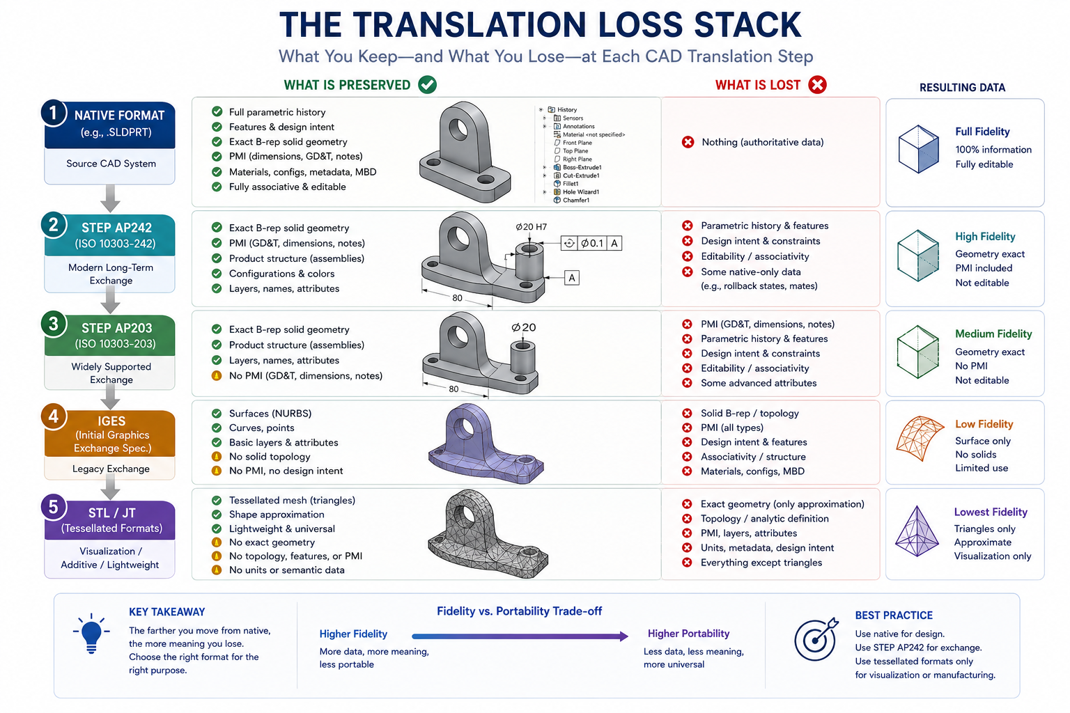
| Format | Type | Parametric History | Solid B-Rep | Assembly Structure | PMI/GD&T | Best Use Case |
| STEP AP203 | Neutral | No | Yes | Yes (limited) | No | Basic solid geometry exchange, older systems |
| STEP AP214 | Neutral | No | Yes | Yes | Partial | Automotive multi-CAD exchange, color/layer |
| STEP AP242 | Neutral | No | Yes | Yes (full) | Yes (full) | Current standard, GD&T, PMI, composite structures |
| IGES | Neutral | No | Surfaces only | No | No | Legacy exchange, 2D drawings, surface models |
| Parasolid (.x_t) | Kernel | No | Yes (exact) | Yes | No | High-fidelity solid exchange within Parasolid apps |
| ACIS (.sat) | Kernel | No | Yes (exact) | Yes | No | Exchange within ACIS-based CAD tools |
| JT | Visualization | No | Lightweight | Yes | Yes | DMU, visualization, PLM/PDM integration |
| 3D PDF | Visualization | No | Tessellated | Yes | Embedded annotations | Supplier communication, non-CAD stakeholders |
| Native SLDPRT etc. | Native | Yes (full) | Yes (exact) | N/A | Yes (if modeled) | In-tool editing only, not for cross-platform exchange |
Why Parametric History Is Always Lost in Translation
The most fundamental limitation shared by every neutral exchange format, including STEP at every application protocol level, is the complete loss of parametric history. Parametric history is the sequence of feature operations (sketches, extrusions, cuts, fillets) and the relationships between them (constraints, equations, references) that define how the model was built. This information exists only in the native CAD file format and is specific to the CAD system that created it.
When a model is exported to any neutral format, the translator evaluates the current state of all features and outputs the resulting geometry as a snapshot: the surfaces, edges, vertices, and their topological relationships at the moment of export. The reasoning that produced that geometry, the parameters, constraints, and features, does not exist in the output file because no neutral format has the schema to represent it.
This loss is structural, not a translator defect. It means that a STEP file received from a supplier is always a dumb solid: accurate geometry at the moment of export, with no ability to propagate design changes through the parametric relationships that the supplier used to create it. Any modifications made to the received geometry must be made through direct modeling or surface editing tools rather than through parametric feature modification.
The B-Rep vs Surface Distinction: Why It Matters for Downstream Use
Boundary Representation (B-Rep) is the mathematical representation used by all modern parametric CAD systems to describe solid geometry. A B-Rep solid consists of faces (surface geometry), edges (curves where faces meet), vertices (points where edges meet), and a topological data structure that records how these elements connect to form a watertight closed volume. The solid is watertight: every face is connected to adjacent faces along its edges, and the interior and exterior of the solid are unambiguously defined.
STEP carries B-Rep data correctly, which is why STEP-imported solids can be used directly for FEA meshing, CAM toolpath generation, and interference checking without additional repair. IGES exports surface geometry without the B-rep topological structure, meaning the received surfaces are independent shells that may or may not stitch together into a watertight solid on the receiving end. The absence of B-Rep in IGES is the single technical reason why STEP has superseded IGES as the preferred exchange format for solid mechanical design.
| What is the best format for CAD file exchange between different CAD systems? STEP AP242 is the current industry standard for solid geometry exchange between different CAD platforms. It preserves solid B-Rep geometry, assembly structure, and PMI/GD&T data. Use it for all new engineering data exchange. IGES should only be used when the receiving system does not support STEP, which is rare for any software purchased after 2005. |
The Ten Most Common CAD Translation Errors and How to Fix Each One
Translation errors fall into predictable categories that correspond to specific technical failure modes in the translation process. The table below maps each error type to its cause, detection method, fix approach, and severity. The sections that follow explain the most damaging error types in the depth required to fix them reliably.
| Error Type | Cause | How to Detect | Fix Approach | Severity |
| Open edges / surface gaps | Tolerance mismatch between sending/receiving kernel | Geometry check tool, watertight test | Geometry healing tool, stitch surfaces | High – prevents meshing and analysis |
| Degenerate edges | Numerical precision errors during B-rep rebuild | Edge length analysis, quality check | Rebuild affected edge, re-export via kernel format | High – causes CAM toolpath failures |
| Non-manifold geometry | T-junctions, zero-thickness walls in source model | Topology check, manifold validation | Fix source model geometry before re-export | Very High – blocks all downstream use |
| Face normal reversal | Inside-out surface orientation after translation | Visual inspection (dark faces), normal analysis | Flip normals in receiving tool, or heal during import | Medium – causes rendering and analysis errors |
| Short edges / slivers | Floating point rounding at intersection curves | Min edge length analysis | Simplify geometry, merge near-coincident edges | Medium – degrades mesh quality |
| Missing PMI / GD&T data | Format does not support PMI (e.g. IGES) or wrong AP | Compare source drawing to received model | Use STEP AP242 with PMI export enabled | High – critical for Model Based Definition |
| Unit system error | Source in mm, target assumes inches (or vice versa) | Compare overall dimensions to known values | Re-import with explicit unit override, scale geometry | Very High – all dimensions wrong by 25.4x |
| Assembly structure loss | Flat IGES export collapses hierarchy | Check part count, assembly tree | Use STEP with assembly structure option enabled | High – prevents assembly-level analysis |
| Tessellation chord error | Coarse tessellation setting on export (STL/JT) | Measure gap between mesh and true curve | Re-export with tighter chord tolerance setting | High for tight-tolerance parts |
| Color and appearance loss | AP203 does not carry color; non-standard layer mapping | Visual comparison source vs target | Use AP214 or AP242 with color/layer mapping enabled | Low – cosmetic only in most cases |
Open Edges and Surface Gaps: The Most Frequent Solid Translation Failure
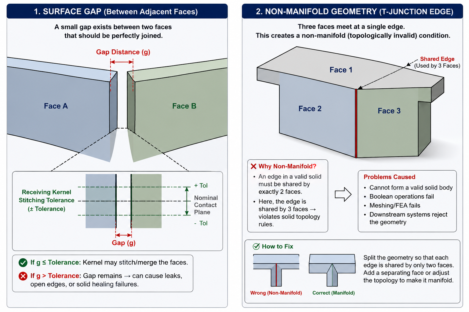
Open edges are the most commonly encountered STEP and IGES translation error. They occur when adjacent faces in the translated solid do not share edges within the geometric tolerance of the receiving system. The translated faces exist in the model but they do not form a watertight closed solid because the edges between them are either missing, duplicated, or offset by a small distance that exceeds the receiving system’s topological stitching tolerance.
The root cause is usually a tolerance mismatch between the sending and receiving geometry kernels. SolidWorks uses the Parasolid kernel, which has its own internal geometric tolerance for defining when two edges are coincident. CATIA V5 uses the CGM kernel with different tolerances. When a model is exported from one kernel and imported into another, edge positions that were coincident within the exporting kernel’s tolerance may fall outside the receiving kernel’s tolerance, producing gaps that did not exist in the original model.
The fix depends on the severity of the gaps. Small gaps, typically under 0.1 mm, can be closed using the geometry healing tools built into most professional CAD platforms: SolidWorks Import Diagnostics, Creo Geometry Repair, NX Heal Geometry, and Ansys SpaceClaim’s repair tools all identify open edges and attempt to stitch them closed automatically. Larger gaps require surface editing: extending the faces to meet correctly and then stitching, or modeling replacement surfaces where the gap geometry is too distorted to stitch reliably.
The Unit System Error: Silent, Total, and Catastrophic
The unit system error is statistically less common than surface gaps but far more damaging when it occurs. It happens when the exporting system’s unit setting does not match the receiving system’s assumption about the units of the incoming file. The most common instance is a model exported in millimeters that is opened in an environment configured to expect inches. Since one inch equals 25.4 millimeters, every dimension in the model is wrong by a factor of 25.4. A 50mm bracket becomes a 50-inch structure. A 3mm thread pitch becomes 3 inches.
The insidious characteristic of this error is that the geometry looks completely correct in the receiving system: proportions are preserved, features are formed correctly, the model is watertight and valid. The wrongness is only detectable by comparing specific dimension values to known specifications, which many engineers do not think to do on a received file they trust.
Prevention is straightforward: STEP files carry unit information in their header. Most modern CAD tools read this header and import geometry at the correct scale automatically. But some older systems or misconfigured importers ignore the header and assume a unit based on their own default setting. When receiving any translated file for the first time from a new source, measure a known reference dimension immediately after import and verify it against the specification before using the geometry for any downstream work.
Non-Manifold Geometry: The Error That Blocks Everything Downstream
Non-manifold geometry is a topological condition where a solid contains edges shared by more than two faces, zero-thickness walls (two coincident faces with no volume between them), or T-junctions where an edge of one face terminates in the middle of another face’s surface. This geometry is mathematically invalid as a solid: it cannot be unambiguously defined as having a volume, an interior, or an exterior.
Non-manifold geometry blocks virtually all downstream engineering operations: FEA meshing fails because the mesh generator cannot determine inside from outside. CAM toolpath generation fails because the tool cannot establish a consistent material boundary. Interference checking produces false results. 3D printing slicers cannot generate valid layer boundaries.
Non-manifold geometry is rarely created by translation itself. It almost always originates in the source model and is exposed by translation. A zero-thickness wall that existed in the source model was topologically connected to adjacent faces within the source kernel’s tolerance, masking the defect. Translation to a different kernel removes that connection, exposing the non-manifold condition. The only correct fix is to repair the source model geometry and re-export, not to attempt to fix the translated file.
Detection uses the geometry check tools available in all professional CAD platforms. In SolidWorks, the Check Entity function under the Evaluate menu reports non-manifold conditions. In Creo, Model Check identifies degenerate topology. In NX, the Examine Geometry command reports non-manifold edges. Run these checks on any translated file before committing it to downstream use.
STEP AP203 vs AP214 vs AP242: Choosing the Right Protocol
STEP is not a single format. It is a family of Application Protocols, each defining a different scope of engineering data that can be carried in the STEP container. Choosing the wrong application protocol is one of the most common avoidable translation errors, because it silently discards data that the sender believes they exported and the receiver assumes was included. Understanding the three protocols that are relevant to mechanical engineering is essential for making the right choice for each exchange scenario.
STEP AP203: Configuration Controlled 3D Design
AP203 was the first widely deployed STEP protocol for 3D solid geometry exchange. It carries solid and surface geometry with full B-Rep topology, assembly structure with component positioning, and basic product metadata. What it does not carry: color, layer assignments, surface finish attributes, and any form of PMI or GD&T annotation.
AP203 is still supported by virtually every CAD system because of its long history, and it remains appropriate for scenarios where pure geometric exchange with no annotation data is needed. Its limitation is that it exports all geometry in a single undifferentiated color (typically gray) with no visual differentiation between components, and it carries no manufacturing information beyond the geometry itself.
STEP AP214: Core Data for Automotive Mechanical Design
AP214 extended AP203 to carry color information, layer data, and a broader set of geometric entity types relevant to automotive design. It became the dominant exchange format for automotive supplier chains through the 2000s and 2010s and is still used extensively in that industry. AP214 is appropriate when visual differentiation between components matters and when the receiving system is in the automotive supply chain where AP214 support is universal.
AP214 carries a partial implementation of GD&T in the form of dimensional tolerances attached to specific geometry, but this implementation is not comprehensive enough to support Model Based Definition workflows where the 3D model replaces the 2D drawing as the primary definition of the product. For MBD workflows, AP242 is required.
STEP AP242: The Current Standard for Complete Engineering Data Exchange
AP242 is the current STEP standard, released in 2014 and continuously updated since. It combines the geometric capabilities of AP203 and AP214 with a comprehensive PMI implementation that supports GD&T annotations compliant with ASME Y14.5 and ISO 1101, datum definitions, surface finish specifications, weld symbols, and tolerance notes. It also adds support for composite material layer definitions, kinematics and mechanism data, and structural finite element model data.
For any exchange scenario where the 3D model must carry manufacturing information (tolerances, GD&T callouts, surface finish, weld requirements), AP242 is the only STEP protocol that can carry this data correctly. Exporting from a system that has PMI modeled in the 3D model and then transmitting as AP203 or AP214 silently discards all of that information. The receiving party sees only the geometry, with no PMI, and has no indication that any annotations existed in the source model.
Most major CAD systems added AP242 export capability between 2014 and 2018. If your team’s CAD software is recent enough to support it, AP242 should be the default STEP export protocol for all engineering data exchange, replacing AP214 for new programs and AP203 for scenarios where PMI is relevant.
| Protocol Selection Quick Reference Use AP203 only when exchanging pure geometry with a legacy system that cannot handle AP214 or AP242. Use AP214 when color and layer information matters and the receiving system is in the automotive supply chain. Use AP242 for all new engineering programs, all Model Based Definition workflows, and any exchange where GD&T or PMI must survive translation. When in doubt, AP242 is always the right choice for modern engineering exchange. |
Kernel-Level Translation: Bypassing STEP When Geometry Fidelity Is Critical
When STEP translation consistently produces geometry errors that healing tools cannot fully resolve, the answer is often not to improve the STEP export settings but to bypass STEP entirely and use kernel-level translation: exporting geometry in the native format of the geometric kernel used by the source CAD system and importing it directly in the receiving system using the same kernel.
The Parasolid Kernel Format (.x_t and .x_b)
Parasolid is the geometry kernel used by SolidWorks, Siemens NX, Solid Edge, and many other major CAD platforms. It is also licensed by several CAM systems including Mastercam and HyperMill. When two systems share the Parasolid kernel, exchanging geometry via Parasolid native format (.x_t for text or .x_b for binary) eliminates the round-trip conversion through STEP or IGES entirely.
Parasolid-to-Parasolid exchange preserves exact B-Rep geometry with full topological integrity because both systems share the same mathematical representation. There is no approximation, no tolerance mismatch, and no topological reconstruction: the geometry that leaves the sender is identical to the geometry that arrives at the receiver. Surface gaps, degenerate edges, and stitching failures that occur in STEP translation simply do not occur in Parasolid-to-Parasolid exchange.
The limitation of Parasolid exchange is that it does not carry assembly structure in the form that STEP does (though it can carry multi-body assemblies as a collection of bodies in one file), and it does not carry PMI data. For pure geometry exchange where precision matters, particularly for CAM applications where STEP AP242 is optimal for 5-axis toolpaths because it maintains G2/G3 surface continuity without approximation, Parasolid is the alternative when STEP is producing geometry errors that affect machining quality.
The ACIS Kernel Format (.sat and .sab)
ACIS is the geometry kernel used by Autodesk Inventor, Autodesk Fusion 360, and several other CAD and CAM platforms. Like Parasolid, ACIS-to-ACIS exchange between two systems that share the kernel eliminates translation-introduced geometry errors. The ACIS SAT format (.sat for text, .sab for binary) is the kernel-native exchange format.
When receiving geometry from an Inventor or Fusion 360 user into another ACIS-based system, requesting ACIS format rather than STEP will typically produce cleaner geometry at the cost of losing assembly structure and PMI. For precision manufacturing applications where the geometry quality matters more than the annotation data, this tradeoff is often worthwhile.
When to Use Kernel-Level Exchange vs. STEP
The decision between kernel-level exchange and STEP should be made based on the downstream use of the geometry. For pure manufacturing applications where a CAM system needs the cleanest possible solid geometry for toolpath generation, kernel-level exchange is often superior. For any application that requires assembly structure, PMI, or compatibility with a system that does not share the source kernel, STEP AP242 is the correct choice despite its occasional geometry healing requirements.
A practical approach is to use STEP AP242 as the default exchange format and switch to kernel-level exchange only when STEP translation consistently produces specific geometry errors on a particular model or combination of systems. Document which workflows require kernel-level exchange in your team’s data exchange standard so that the knowledge is systematic rather than held individually by the engineer who discovered the workaround.
PMI and Model Based Definition Translation: The Modern Challenge
Product Manufacturing Information (PMI) is the collection of manufacturing annotations attached to the 3D model that, in a Model Based Definition workflow, replaces the traditional 2D engineering drawing as the authoritative definition of the product. PMI includes GD&T feature control frames, datum identifiers, surface finish callouts, weld symbols, thread specifications, tolerance notes, and any other manufacturing requirement that was historically documented on a 2D drawing.
Preserving PMI through CAD translation is one of the most critical and least reliably solved problems in modern engineering data exchange. The reason is that PMI is not just geometry. It is a combination of geometry (the annotation graphical representation), semantic data (the mathematical interpretation of the annotation), and association (the link between the annotation and the geometric entity it applies to). All three elements must survive translation for the PMI to be usable at the receiving end.
The Semantic PMI vs. Graphical PMI Distinction
Graphical PMI is the visual representation of the annotation: the GD&T symbol as it appears in the model’s display. When you look at a feature control frame in a 3D model and see the geometric characteristic symbol, the tolerance value, and the datum references, you are seeing graphical PMI. Graphical PMI can be carried in STEP AP242 as a set of curves and text entities that visually reproduce the annotation in the receiving system.
Semantic PMI is the structured data representation of the annotation: a machine-readable record that a CAM system, CMM programming software, or quality management system can interpret and process automatically. Semantic PMI in STEP AP242 uses a formal schema that encodes the geometric characteristic type, the tolerance value, the datum structure, and the referenced geometry in a way that is both human-readable and machine-processable.
Most engineering teams that work with PMI need semantic PMI, not just graphical PMI, because their downstream tools (CMM programming software, SPC systems, CAM systems) need to read and interpret the annotations programmatically. Receiving graphical PMI in a translated file means someone must manually re-enter the annotation information into the downstream system. Receiving semantic PMI means the annotation transfers automatically into the downstream workflow.
Why PMI Translation Fails and What to Do
PMI translation fails for several reasons. The exporting CAD system may not have a complete AP242 PMI export implementation for all entity types: some vendors have implemented basic GD&T symbol export but have not implemented semantic PMI for all datum structures or composite tolerance specifications. The receiving system may not be configured to read semantic PMI even if it was correctly exported. Or the PMI in the source model may not have been created using the CAD tool’s native annotation features, meaning it was modeled as ordinary text and geometry rather than as linked PMI entities.
The diagnostic approach is to compare the PMI in the source model against the PMI visible in the translated file in the receiving system, entity by entity. Any annotation that is missing or present only as graphical representation without semantic data is a translation failure. The resolution depends on the root cause: if the issue is the exporting system’s PMI implementation, the workaround is to accompany the STEP file with a 2D drawing or 3D PDF that redundantly carries the annotation data. If the issue is the receiving system’s PMI reader, the receiving team needs to configure their system’s AP242 import settings to enable semantic PMI reading.
Read article on: Master Models in CAD: Benefits for Large Engineering Projects
Tessellation Errors: STL, JT, and Mesh Quality for Additive Manufacturing
Tessellated formats convert exact B-Rep geometry into a triangulated mesh that approximates the original surface. This approximation is the source of all tessellation errors: the mesh can only represent flat triangular facets, so any curved surface in the original model is approximated by a collection of triangles whose edges are straight. The quality of the approximation depends on how finely the original surface is subdivided into triangles during export.
The Chord Error Problem Explained Mathematically
Chord error is the maximum distance between the tessellated mesh and the true mathematical surface at any point. When a circle is approximated by a polygon, the chord error is the distance from the middle of any polygon edge to the true circle at that point. For a curved surface tessellated into triangles, the chord error is the maximum sagitta (height of the arc above the chord) across all triangles.
For precision manufacturing, chord error is not cosmetic. For a CNC bore specified at a 25mm diameter with an H7 tolerance of plus 0 and minus 0.021mm, a chord error of 0.05mm in the tessellated model is already 2.4 times outside the tolerance band before any machining has occurred. A CAM system generating toolpaths from a tessellated model with this chord error will produce bores that are consistently undersized by the chord error amount, requiring additional machining passes that were not planned.
The fix is to control the chord tolerance in the STL or JT export settings rather than accepting the default. Most CAD systems export STL with a chord tolerance that is appropriate for visual rendering but too coarse for precision manufacturing. Set the chord tolerance to one-tenth of the tightest manufacturing tolerance in the model: for a 0.02mm H7 tolerance, set the chord tolerance to 0.002mm or tighter. This produces a larger file but ensures that the tessellated geometry is a faithful representation of the precision geometry the manufacturer needs.
STL Watertightness and Mesh Manifold Requirements
3D printing slicers and additive manufacturing systems require STL files to be watertight: every edge in the mesh must be shared by exactly two triangles, with no gaps, no overlapping triangles, and no reversed normals. An STL file that is not watertight cannot be sliced correctly: the slicer cannot determine which regions are inside the model (solid material) and which are outside (air), producing incorrect layer boundaries and potentially dangerous build failures.
Common STL watertightness failures include: gaps between triangles where adjacent faces of the original B-Rep model had small surface gaps that were invisible at normal rendering scale but became open mesh edges after tessellation; reversed normals where a face was modeled as inside-out in the source model and the tessellation faithfully reproduced the inversion; and degenerate triangles where the chord tolerance was too coarse to represent a small geometric feature, producing zero-area or near-zero-area triangles that violate mesh integrity.
Detection uses the mesh analysis tools built into most CAD systems and available in dedicated mesh repair tools such as Materialise Magics, Netfabb, and MeshMixer. Most CAD tools have a mesh analysis option in the STL export dialog that runs the watertightness check before writing the file. Enable this check on every STL export for additive manufacturing and repair any reported issues before transmitting the file.
| Tessellation Chord Tolerance Reference For visual rendering or concept models: chord tolerance 0.1 to 0.5mm (default in most systems). For CNC machining reference: chord tolerance 0.01 to 0.05mm. For precision bearing surfaces or H7/H6 tolerances: chord tolerance 0.001 to 0.005mm. For additive manufacturing (FDM/SLA/SLS): chord tolerance 0.01 to 0.1mm depending on layer resolution. Always set chord tolerance to one-tenth of the tightest tolerance in the model when the tessellated geometry will inform manufacturing dimensions. |
Pre-Export Best Practices: Preventing Translation Errors at the Source
The most effective translation quality strategy is to prevent errors before they occur rather than repairing them after the fact. A structured pre-export workflow applied to every model before it leaves the originating system eliminates a large fraction of the translation errors that downstream teams typically encounter.
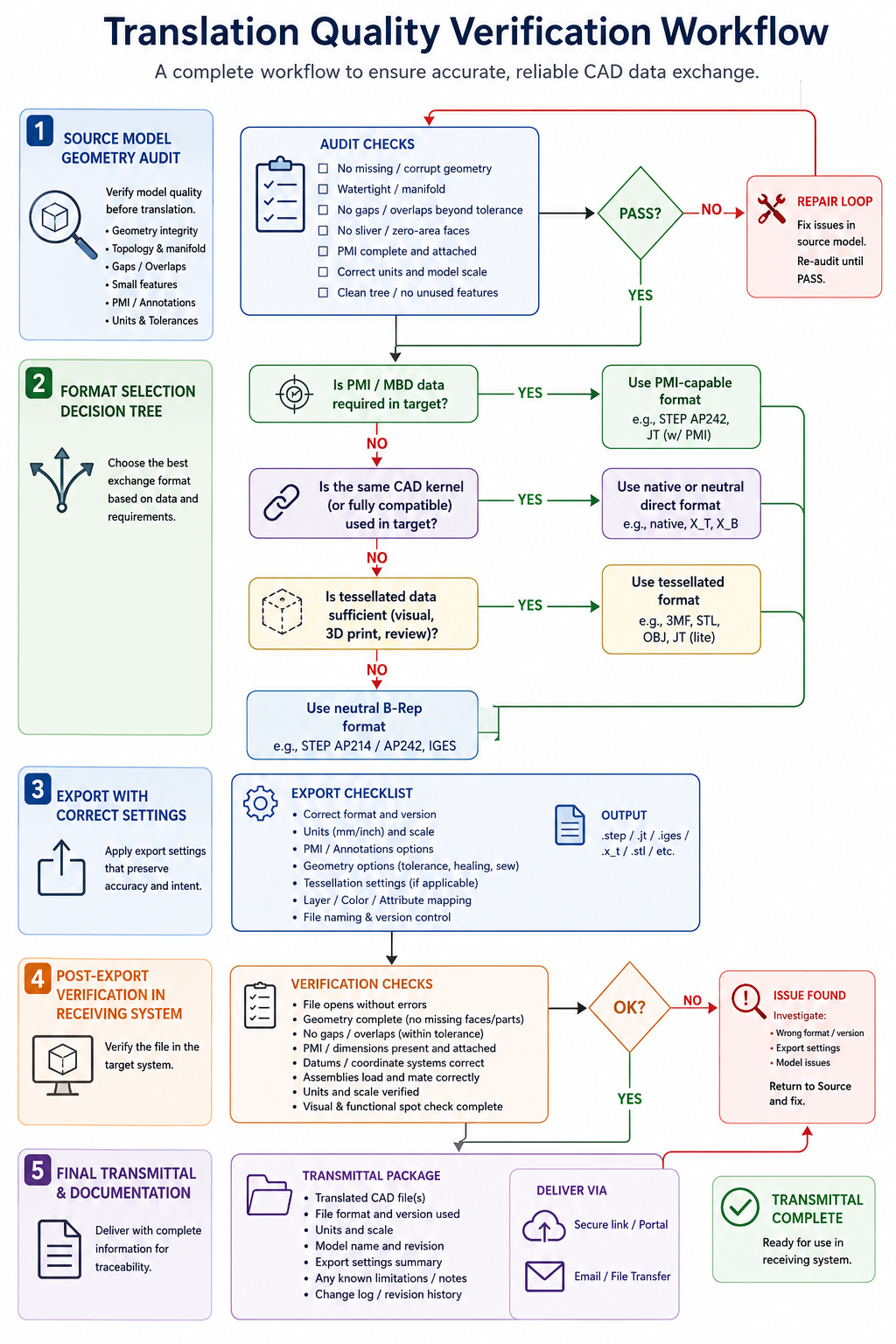
The Pre-Export Geometry Audit
Run the geometry check tool native to your CAD platform on every model before export. This is not an optional quality step. It is a mandatory check that takes under a minute and catches the source geometry problems that become translation errors in the receiving system. In SolidWorks, this is the Check Entity function under Evaluate. In Creo, it is the Geometry Check under Analysis. In Inventor, the Repair Bodies command. In CATIA V5, the Geometry Check function under Analysis.
The check should report zero invalid geometry before export. Any reported invalid geometry: short edges, degenerate faces, non-manifold conditions, zero-thickness features, or open shells that should be closed, must be corrected in the source model before export. Do not export a model that fails this check and expect the receiving system to heal the problems. Some healing is possible, but the sending organization is always in a better position to fix source geometry than the receiving organization is to repair translated geometry.
Read more article on: Design for Assembly: CAD Tips That Cut Production Costs
Simplification Before Export
Complex internal geometry that is not visible or functional from the exterior of a model adds file size, increases translation time, and creates unnecessary opportunities for translation errors. Suppress or remove internal geometry before exporting for manufacturing or supplier use. Thread detail on fastener holes, internal cavity geometry in housings, cosmetic surface features that are represented on the drawing rather than required in the 3D model, and construction geometry used during modeling but not part of the final part shape should all be removed or suppressed before export.
This simplification also benefits the receiving system: a leaner model opens faster, rebuilds faster in the receiving tool, and creates less overhead for CAM, FEA, and visualization applications. Maintaining a full-detail version for the engineering record and a simplified export version for transmission is a best practice that experienced teams implement as a standard step in their release workflow.
Pre-Export Checklist for CAD Translation |
Geometry Healing: Tools and Techniques for Fixing Translated Geometry
When translated geometry arrives with errors despite a clean source model and correct export settings, the geometry healing process begins. Every professional CAD platform includes geometry healing tools, and several dedicated interoperability toolkits exist specifically for translation quality management. Understanding what these tools can and cannot fix helps set realistic expectations for the healing workflow.
Native Healing Tools by Platform
SolidWorks Import Diagnostics is the most accessible healing interface available in any major CAD platform. It runs automatically when a STEP or IGES file is imported and presents a report of faulty faces and open edges, with buttons to attempt automatic repair of each category. For small gaps and minor stitching failures, Import Diagnostics resolves the majority of errors without manual intervention. For larger gaps or more complex topology failures, it identifies the specific faces and edges that need manual repair through surface editing.
PTC Creo Geometry Repair provides a similar workflow but with additional tools for specifically addressing the types of errors common in Creo’s conversion from STEP and IGES. The Geometry Repair tool in Creo categorizes errors by type and allows targeted repair actions: close gaps, flip normals, remove short edges, and fill holes in surfaces. Creo’s repair tools are particularly effective for models exported from non-PTC systems that experience edge tolerance mismatches when imported into the CGM kernel.
Siemens NX Heal Geometry and Solid Edge’s equivalent provide automated healing with detailed reporting. NX’s healing tools are well-regarded for their ability to handle complex geometry from aerospace and automotive sources, which tend to involve the kinds of large, complex freeform surfaces where topology errors are most damaging.
Ansys SpaceClaim is frequently used as a dedicated geometry repair environment precisely because its direct modeling tools make it fast to manually repair faces and edges that automated healing tools cannot resolve. Engineers receive a broken STEP file, open it in SpaceClaim, use the repair tools for automated fixes, then switch to direct face editing for the remaining issues, and export a clean STEP or Parasolid file for use in the final application.
Dedicated Interoperability Tools
For organizations that handle large volumes of translated geometry or that require certified translation quality for regulated industries, dedicated CAD interoperability toolkits provide capabilities beyond what CAD platform healing tools offer. Spatial’s 3D InterOp SDK, CADfix from ITI, and TransMagic provide translation and healing workflows that detect and correct over 150 defect types, generate detailed quality reports, and in some cases certify that translated geometry meets specific geometric accuracy standards.
These tools are particularly valuable in aerospace and automotive supply chains where a supplier’s ability to deliver verified-quality CAD data to a customer is a contractual requirement. A company using TransMagic or CADfix can provide a geometry quality certificate with every file they deliver, documenting the translation errors detected and the corrections applied. This transforms translation quality from an engineering workflow concern into a documented, auditable data quality process.
When Healing Is Not Enough: Rebuilding From Scratch
There are classes of translation errors that no healing tool can resolve: cases where the source model contains fundamental geometric problems that produce invalid topology regardless of how the translation is tuned or how thoroughly the received geometry is healed. In these cases, the correct decision is to request the source model from the sender and ask them to fix the source geometry before re-exporting, or to rebuild the affected geometry from scratch using the translated file as a reference rather than attempting further healing.
The decision point is when the time invested in healing exceeds the time to rebuild: typically when more than 20 percent of the faces in the model require manual repair. Rebuild the geometry by creating new surfaces or solids that reference the geometry of the damaged model visually, using the coordinates and dimensions from the original model’s specification as the driving values rather than the broken face geometry as the reference. This produces cleaner geometry than aggressive healing and typically takes comparable time to a thorough healing attempt on a severely damaged model.
Translation in the Modern Engineering Workflow: Supplier Communication and MBD
CAD data translation does not happen in isolation. It sits within a broader engineering communication workflow that determines how data flows between design, manufacturing, quality, suppliers, and customers. Understanding where translation fits in that workflow, and how to design the workflow to minimize translation-introduced errors, is the strategic layer above the technical fixes covered in earlier sections.
Designing the Supplier Communication Workflow Around Translation Constraints
Most supplier communication workflows evolved around PDF drawings because PDFs are universally readable, they carry 2D annotation data completely and without loss, and they do not require the recipient to have a CAD license. The challenge is that PDF drawings are a one-way, non-parametric communication medium: the supplier sees the drawing but cannot use the 3D geometry for CAM programming, inspection planning, or simulation without separately receiving a 3D file.
Best practice for supplier communication in 2026 combines three file types: the STEP AP242 file for geometry and PMI, the 3D PDF for stakeholders who need to view the model without CAD software, and the 2D drawing PDF as a redundant reference for inspection and fabrication contexts where the 2D format is preferred. This combination ensures that every recipient has the data they need in the format they can use, while the STEP AP242 file carries the authoritative geometry and PMI for manufacturing and inspection purposes.
Model Based Definition and the Future of Translation
Model Based Definition (MBD) is the practice of using the 3D CAD model as the authoritative definition of the product, replacing or significantly reducing the role of 2D drawings. MBD is increasingly mandated in aerospace (Boeing, Airbus, and major defense primes have adopted it), automotive (IATF 16949 explicitly supports MBD workflows), and medical device manufacturing (FDA guidance supports electronic design records).
The translation challenge in an MBD workflow is more significant than in a drawing-based workflow because the model must carry all manufacturing information that was previously on the drawing: not just geometry but GD&T, surface finish, material specifications, and process notes. This requires STEP AP242 with full semantic PMI export, correct configuration of the receiving system’s AP242 PMI reader, and a verification step at the receiving end that confirms PMI was received correctly before manufacturing or inspection activities begin.
As MBD adoption grows, the ability to reliably translate semantic PMI between CAD systems becomes a competitive differentiator for engineering organizations and their supplier chains. Suppliers who can receive and process semantic PMI directly from customer STEP files can automate their CMM programming, first article inspection, and SPC data collection, reducing their internal cost and improving their delivery reliability. This capability starts with understanding and correctly implementing the translation workflow covered in this article.
Frequently Asked Questions
Q: What is the best CAD format for exchanging files between different CAD systems?
STEP AP242 is the current industry standard for exchanging solid 3D geometry between different CAD platforms. It preserves solid B-Rep geometry with full topological integrity, assembly structure, and PMI/GD&T annotations when the exporting system supports AP242 PMI export. Use STEP AP242 for all new engineering data exchange programs. IGES should only be used when the receiving system does not support STEP, which is very rare for any software in active maintenance. For systems that share the same geometry kernel (such as two SolidWorks installations sharing the Parasolid kernel), native kernel format exchange provides better geometry fidelity than STEP for pure geometry without annotation data.
Q: Why do I get open edges and surface gaps after importing a STEP file?
Open edges occur when the geometric tolerance of the receiving CAD system’s kernel differs from the sending system’s kernel. Edges that were coincident within the sending system’s tolerance may fall outside the receiving system’s stitching tolerance, producing gaps that did not exist in the source model. The fix is to run the receiving system’s geometry healing tool (Import Diagnostics in SolidWorks, Geometry Repair in Creo, Heal Geometry in NX) to stitch the gaps closed. For persistent gaps, the sending engineer should run a geometry check on the source model before export and ensure the source geometry contains no pre-existing surface quality issues that the translation has revealed.
Q: What is the difference between STEP AP203, AP214, and AP242?
AP203 carries solid B-Rep geometry and basic assembly structure with no color or annotation data. AP214 adds color, layer data, and partial GD&T support, and is widely used in automotive supply chains. AP242 is the current comprehensive standard that adds full semantic PMI and GD&T support compliant with ASME Y14.5 and ISO 1101, composite material definitions, and kinematics data. For any program that uses Model Based Definition or requires GD&T data to survive translation, AP242 is the only appropriate choice. For programs where geometry alone is sufficient, AP214 is acceptable but AP242 is preferable as the forward-compatible choice.
Q: How do I fix a unit system error in a translated CAD file?
If a model was exported in millimeters but imported as inches (or vice versa), all dimensions will be wrong by a factor of 25.4. The fix depends on your CAD platform: in most systems you can re-import the file with an explicit unit override that specifies the correct source units, which applies the 25.4 scale correction automatically. Alternatively, scale the entire imported geometry by 25.4 (or 1/25.4) to convert from the wrong unit to the correct one. To prevent this error: verify that the exported STEP file includes a unit header (it should by default in any modern exporter), and measure one reference dimension immediately after any import to confirm it matches the known specification before proceeding with any downstream work.
Q: What is non-manifold geometry in CAD and why is it a problem?
Non-manifold geometry is a topological condition in a solid model where edges are shared by more than two faces, where zero-thickness walls create coincident face pairs, or where T-junctions exist within the surface structure. Non-manifold geometry is mathematically invalid as a solid because it cannot unambiguously define an interior volume. It blocks virtually all downstream engineering operations: FEA meshing fails, CAM toolpath generation fails, interference checking produces false results, and 3D printing slicers cannot generate valid layer boundaries. Non-manifold geometry almost always originates in the source model and is exposed by translation. The correct fix is to repair the source model and re-export, not to attempt repair of the translated file.
Q: What is semantic PMI and why does it matter for manufacturing?
Semantic PMI is the machine-readable structured data representation of GD&T and manufacturing annotations in a 3D model, as carried by STEP AP242. Unlike graphical PMI (which is just a visual display of the annotation), semantic PMI encodes the geometric characteristic type, tolerance value, datum references, and associated geometry in a way that downstream software can read and process automatically. CMM programming software that reads semantic PMI can automatically generate inspection routines. SPC systems can automatically collect tolerance data. CAM systems can identify critical surfaces. Without semantic PMI, every downstream team must manually re-enter annotation data from a 2D drawing or visual model inspection, creating both labor overhead and a risk of data entry errors in the manufacturing record.
Q: What tessellation chord tolerance should I use when exporting STL for 3D printing or CNC?
Set the chord tolerance to one-tenth of the tightest manufacturing tolerance in the model. For standard FDM 3D printing with 0.2mm layer height, a chord tolerance of 0.02mm is appropriate. For SLA or SLS printing at finer resolution, use 0.005mm to 0.01mm. For CNC reference geometry on standard tolerance parts (plus or minus 0.1mm), use 0.01mm chord tolerance. For precision bores at H7 tolerance (approximately plus or minus 0.02mm on a 25mm bore), use 0.002mm chord tolerance to ensure the tessellated geometry does not introduce dimensional error that falls within the tolerance band. The default chord tolerance in most CAD systems is set for visual quality, not manufacturing precision, and should never be used for precision manufacturing exports without review.
Conclusion:
CAD data translation is not an IT function or a file management task. It is an engineering process with measurable quality outcomes that directly affect manufacturing cost, schedule, and product integrity. A translated model with surface gaps that reach a CAM system produces incorrect toolpaths. A STEP file exported as AP203 from an MBD model silently discards all GD&T data that the manufacturing team needs. A tessellated STL file with default chord tolerance introduces dimensional errors that fall within the tolerance bands of precision features.
Every one of these failures is preventable with the systematic application of the knowledge in this article: choosing the right format and protocol for each use case, running the geometry audit before export, configuring the export settings correctly, verifying the output in the receiving system, and applying geometry healing to any errors that survive the process. None of this requires expensive specialized software. It requires deliberate process design applied consistently to every data exchange in the team’s workflow.
The broader implication is that as Model Based Definition adoption grows and 3D models increasingly replace 2D drawings as the authoritative definition of products, translation quality becomes more important, not less. When the model is the drawing, a model that arrives at the supplier with missing PMI or degraded geometry is not just an inconvenience. It is a breakdown in the engineering definition of the product, with consequences that propagate from the supplier’s shop floor into the product’s quality and the organization’s liability.
Build the pre-export checklist into your team’s data release workflow. Make the post-import verification a mandatory step before any translated geometry is used in manufacturing or quality activities. Document which translation paths in your organization require kernel-level exchange rather than STEP. And ensure that everyone who sends and receives CAD data understands what each format can and cannot carry, so that the choice of format is deliberate rather than defaulted.
Deepen your CAD engineering foundation with our guides on multi-body modeling techniques, CAD file management best practices, reusable CAD libraries, design for assembly, and the CAD modeling mistakes that delay manufacturing.