Tag: CAD drawings

  • How Much Does CAD Drafting Cost? 2026 Pricing Guide

    How Much Does CAD Drafting Cost? 2026 Pricing Guide

    One of the most common questions engineering managers, architects, and small business owners ask when a new project lands on their desk is deceptively simple: what is this going to cost in drafting?

    The honest answer is that CAD drafting costs span a wide range, from under $50 for a basic conversion task to well over $50,000 for a complex commercial construction drawing package. The range is not arbitrary. It reflects real differences in drawing complexity, drafter experience, project discipline, delivery speed, and where in the world the work is being done.

    Most pricing articles on this topic give you a number and move on. This guide goes deeper. We break down costs by drawing type, discipline, pricing model, and provider category. We explain every factor that moves the price up or down. We include a practical budget-planning section and a red flag list for quotes that do not pass the smell test. By the end, you will know not just what CAD drafting costs, but why it costs what it does, and how to get better value from every dollar you spend.

    Quick Answer: CAD Drafting Cost at a Glance
    If you need a number right now, here is where most CAD drafting projects land based on current market data compiled from vendor pricing pages, industry surveys, and published rate data for 2026-2026:
    CAD drafting cost comparison chart showing price ranges for 2D drafting, 3D modeling, BIM services, and shop drawings in 2026
    Pricing MetricTypical RangeNotes
    Hourly rate (domestic freelancer)$45 – $95/hrVaries by discipline and experience
    Hourly rate (domestic firm)$75 – $150/hrIncludes overhead, QA, account management
    Hourly rate (offshore firm)$8 – $35/hrVaries significantly by region and quality tier
    Per-sheet rate (2D CAD conversion)$45 – $250/sheetRush turnaround doubles or triples cost
    Simple 2D drawing package$150 – $800Single-page layouts, basic floor plans
    Standard residential drawing set$800 – $3,500Full permit-ready plans for a home
    Commercial drafting package$5,000 – $30,000+Multi-discipline, multi-sheet sets
    3D CAD model (single component)$300 – $2,500Complexity and tolerance precision drive cost
    BIM model (full building)$8,000 – $50,000+Depends on LOD and number of disciplines
    Monthly retainer (outsourced)$1,200 – $6,000/moDedicated or shared resource block
     Important framing:  These ranges reflect real market data, not optimistic estimates. The bottom of each range represents straightforward work from lower-cost providers. The top reflects complex, high-stakes deliverables from experienced domestic firms. Most real projects land somewhere in the middle.

    2. What Determines CAD Drafting Pricing? The 7 Core Variables

    CAD drafting is not a commodity where one price fits all. Every quote you receive reflects a specific combination of the following factors. Understanding each one helps you assess whether a quote is fair, and gives you tools to control your costs.

    Infographic showing seven variables that determine CAD drafting cost complexity, drafter experience, software, turnaround time, provider location, revisions, and project volume

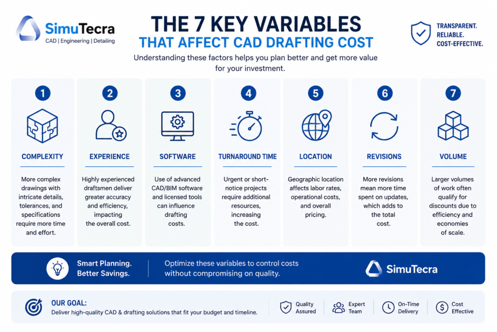
    Variable 1: Drawing Complexity

    Complexity is the single biggest cost driver in CAD drafting. A simple 2D floor plan redraw with clean linework and basic dimensions might take a skilled drafter three to five hours. The same space drawn with structural details, MEP coordination, material specifications, and permit-ready annotation can take fifteen to thirty hours. That difference directly multiplies your cost.

    Complexity factors include the number of distinct components or rooms, the level of annotation and dimensioning required, whether the drawing needs to meet code compliance or permit submission standards, how many layers and disciplines must be coordinated, and whether 3D modeling or BIM data is involved alongside 2D output.

    Variable 2: Drafter Experience and Specialization

    An entry-level drafter working in AutoCAD LT will produce basic 2D layouts accurately and affordably. A senior mechanical engineer who also drafts will charge three to four times more per hour, but may deliver a complete SolidWorks assembly package with GD&T annotations, BOM, and manufacturing notes in a fraction of the time. Specialization commands a premium. Structural steel detailing, medical device drafting, aerospace documentation, and MEP coordination drawings all require expertise that general drafters do not have, and the market rates for specialists reflect that.

    Variable 3: Software and Deliverable Format

    The software platform matters both for capability and cost. An AutoCAD 2D drawing is the most common and typically the least expensive output. SolidWorks or CATIA 3D models involve more complex workflows and higher-cost software licenses, which factor into quoted rates. Revit BIM deliverables require BIM-trained professionals and carry a premium over standard CAD. If you require deliverables in a specific format (native DWG, STEP, IFC, PDF, DXF), or need files structured to a specific standard like ISO or AIA layering, mention this upfront, as non-standard requirements affect time and cost.

    Variable 4: Turnaround Time

    Rush work costs more, often significantly more. Most CAD drafting providers have tiered pricing based on delivery speed. Standard turnaround (5 to 10 business days) is typically the baseline rate. Three-day delivery often carries a 25 to 50 percent premium. Same-day or next-day delivery, when available, can double the base price. If your timeline is flexible, communicate that clearly. Some providers discount work with relaxed deadlines, using it to fill gaps between priority projects.

    Variable 5: Provider Location

    Where the drafting is done dramatically affects what you pay. A domestic US firm in a major metropolitan area will charge two to five times what an equivalent-quality offshore firm in India or the Philippines charges for the same drawing. The cost difference is real, but so are the tradeoffs in communication, time zone overlap, and IP handling. The pricing section on domestic versus offshore providers covers this in detail.

    Variable 6: Number of Revisions

    Revisions are a significant and often underestimated cost driver. Most drawing packages include a defined number of revision rounds in the base quote (commonly one or two rounds of minor changes). Changes beyond that scope are billed at the hourly rate, which can substantially increase total project cost. Poor upfront briefing is the main cause of excessive revision cycles. The clearer and more complete your design intent and specifications are at the start, the fewer revision rounds you will need.

    Variable 7: Project Scale and Volume

    Volume pricing is real. A single drawing sheet costs proportionally more than a batch of fifty similar sheets. If you have an ongoing, high-volume drafting need, most firms will offer a reduced per-sheet or per-hour rate in exchange for a committed volume or retainer arrangement. Conversely, minimum project charges (typically $150 to $250 for most firms) mean that very small one-off requests are often not worth outsourcing individually.

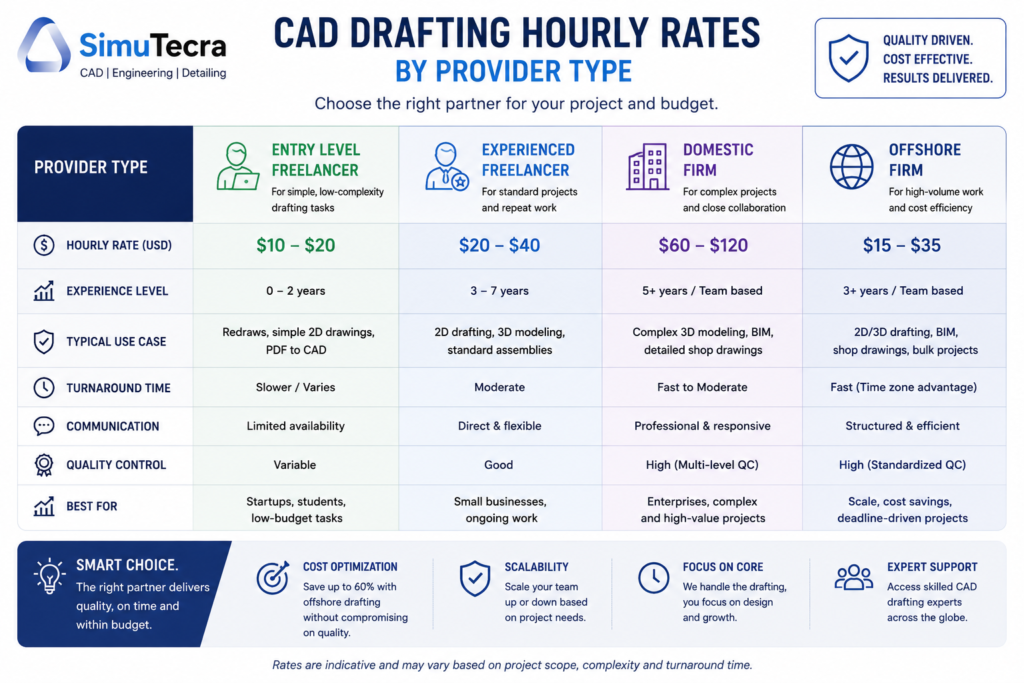
    3. CAD Drafting Hourly Rates: A Realistic Breakdown

    Hourly billing is the most transparent and flexible pricing model for CAD drafting, and it is the dominant model for iterative or undefined-scope work. Here is what the market looks like in 2026-2026 across provider types and experience levels.

    Bar chart comparing CAD drafting hourly rates by provider type from entry-level freelancers to domestic firms in 2026
    Provider TypeEntry LevelMid LevelSenior / SpecialistNotes
    US Domestic Freelancer$30 – $45/hr$45 – $75/hr$75 – $120/hrRates vary by discipline; structural and MEP specialists at the top
    US Domestic Firm$60 – $80/hr$80 – $120/hr$100 – $175/hrIncludes project management, QA, software overhead
    UK / Western Europe Firm£45 – £65/hr£65 – £100/hr£95 – £150/hrComparable to US in GBP; EU regulations familiarity a plus
    Eastern Europe (Poland, Romania)$20 – $35/hr$35 – $55/hr$50 – $80/hrStrong technical quality; growing for BIM and complex drafting
    India-Based Firm$8 – $15/hr$15 – $25/hr$22 – $40/hrLargest offshore talent pool; quality varies significantly
    Philippines-Based Firm$10 – $18/hr$18 – $30/hr$25 – $45/hrStrong English proficiency; good AEC and MEP drafting capability

    What Is Included in an Hourly Rate?

    When you hire a domestic firm at $100 per hour, you are not just paying for the drafter’s hands on a mouse. That rate typically covers:

    • The drafter’s time and expertise
    • Software license costs (AutoCAD at $1,975/year, Revit at $2,310/year, SolidWorks at $4,000+ per year)
    • Internal quality review before delivery
    • File management and delivery infrastructure
    • Project management and communication overhead
    • The firm’s business overhead including insurance, office, and administrative staff

    When you hire a solo freelancer at $55 per hour, most of those costs are lower or absent, which explains the rate difference. Neither is inherently better — the right choice depends on your project’s complexity and what level of process and oversight you need.

    4. Per-Sheet and Per-Project Pricing: When Each Makes Sense

    Per-Sheet Pricing

    Per-sheet pricing is common for CAD conversion work, PDF-to-DWG conversion, permit drawing sets, and other tasks where each sheet is a discrete, standardized deliverable. It is popular with clients because it is predictable: you know how many sheets you need, you multiply by the rate, and you have your budget.

    Drawing Sheet TypeTypical Per-Sheet RateRush MultiplierNotes
    PDF to CAD conversion (basic)$45 – $90/sheet2 – 3xSimple linework, minimal annotation
    PDF to CAD conversion (detailed)$90 – $180/sheet2 – 4xFull annotation, dimensions, notation
    Architectural floor plan (new draw)$150 – $350/sheet1.5 – 2xOriginal drafting from sketches or notes
    Structural detail sheet$200 – $450/sheet1.5 – 2.5xIncludes member sizing, connection details
    MEP (mechanical/electrical/plumbing)$175 – $400/sheet1.5 – 3xCoordination complexity adds cost
    Shop drawing (fabrication)$150 – $350/sheet1.5 – 2xWeld symbols, tolerances, BOM
    Civil site plan$250 – $600/sheet1.5 – 2xSurvey data integration, grading, utilities
    On rush pricing:  One published provider (CAD/CAM Services) lists a flat rate of $185 per D or E size AutoCAD 2D sheet at standard turnaround. The same work at rush turnaround (24 hours) typically runs $370 to $550. Plan your deadlines accordingly.

    Per-Project (Fixed Fee) Pricing

    Fixed-fee pricing works well when the scope is clearly defined and the deliverables are well-understood. The drafter agrees to produce a specific set of outputs for a set price. You get budget certainty; the drafter accepts the risk if the job takes longer than estimated.

    Fixed-fee pricing is common for residential drawing packages, permit submission sets, and defined industrial or manufacturing drawing packages. It is less common for complex commercial or industrial projects where scope evolves during the engagement.

    Project TypeTypical Fixed-Fee RangeWhat Is Usually Included
    Simple 2D drawing (single sheet)$150 – $400Line conversion or basic redraw, one revision round
    Small residential renovation drawings$800 – $2,700Floor plans, elevations, basic sections for permit
    Full custom home drawing set$3,500 – $10,000+Full architectural set: plans, sections, elevations, details
    Small commercial building (permit set)$5,000 – $15,000Multi-discipline permit package, ADA compliance
    Medium commercial / industrial$15,000 – $35,000Full structural, MEP, architectural coordination
    Large commercial or industrial project$35,000 – $100,000+Multiple disciplines, extensive coordination, BIM deliverables
    Product design (simple mechanical part)$300 – $1,5003D model, 2D drawing package, BOM
    Product design (complex assembly)$2,000 – $15,000+Multi-component assembly, GD&T, manufacturing drawings

    5. Cost by Drawing Type and Discipline

    CAD drafting costs vary significantly across disciplines. The differences are not arbitrary: they reflect the level of specialized knowledge required, the complexity of applicable standards and codes, and the typical time investment per drawing.

    Architectural CAD Drafting Costs

    Architectural drafting is one of the most common CAD services and covers a wide range of work from basic floor plans to complex construction document sets. Costs are driven by the number of sheets, the level of detail, and whether permit submission formatting is required.

    • Basic floor plan (single level): $300 – $800
    • Full residential permit set (plans, elevations, sections, details): $1,500 – $5,000
    • Commercial permit-ready drawing package: $8,000 – $30,000+
    • As-built drawings (measured and drawn): $500 – $3,000 depending on size and complexity
    • PDF to AutoCAD conversion (per sheet): $45 – $180

    Architectural drafting rates for domestic freelancers average $75 to $125 per hour. This is substantially less than hiring a licensed architect, whose hourly rates run $200 to $400 per hour. For pure drafting work (translating a design into accurate CAD output), a skilled architectural drafter is the appropriate choice, not an architect.

    Mechanical Engineering CAD Drafting Costs

    Mechanical CAD drafting is where precision is paramount. Drawings must convey exact dimensions, tolerances, material specifications, and surface finish requirements in a format that machinists and fabricators can execute without ambiguity. This level of precision requires experienced drafters and commands higher rates than basic architectural work.

    • Simple machined part (2D drawing): $150 – $600
    • Complex machined part with GD&T: $400 – $1,500
    • 3D solid model (single component): $300 – $2,000
    • Sub-assembly drawing package: $800 – $4,000
    • Full product assembly with BOM and exploded views: $2,000 – $15,000+

    Mechanical CAD specialists in AutoCAD Mechanical, SolidWorks, or CATIA typically bill $65 to $120 per hour domestically. The premium over general drafting rates reflects the knowledge of manufacturing processes, GD&T standards (ASME Y14.5), and the criticality of getting tolerances right.

    Structural Engineering CAD Drafting Costs

    Structural drafting covers foundation plans, framing plans, structural steel details, rebar layouts, and connection details. It sits at the intersection of engineering judgment and drafting skill, meaning the best structural drafters have a solid understanding of structural behavior, not just drafting technique.

    • Foundation plan: $400 – $1,200
    • Structural steel shop drawings (per sheet): $200 – $450
    • Rebar detailing drawings (per sheet): $150 – $350
    • Full structural drawing package for a residential project: $1,500 – $4,000
    • Commercial structural documentation package: $8,000 – $40,000+

    Structural shop drawings are a category where outsourcing to specialized overseas firms is extremely common. Firms in India and the Philippines have built strong capabilities specifically in steel detailing and rebar drawings for US and UK markets, typically charging $15 to $30 per hour for what domestic firms bill at $90 to $150 per hour.

    Civil Engineering CAD Drafting Costs

    Civil CAD drafting covers site plans, grading plans, utility layouts, road designs, and land development drawings. Civil work often involves integration with survey data, GIS systems, and regulatory formatting requirements that vary by municipality.

    • Basic site plan: $500 – $1,500
    • Full land development drawing package: $3,000 – $15,000
    • Road design drawings (per sheet): $300 – $700
    • Utility layout drawings (per sheet): $200 – $500
    • Civil 3D model (grading and drainage): $1,500 – $8,000

    MEP (Mechanical, Electrical, Plumbing) Drafting Costs

    MEP drafting is among the most complex and expensive CAD work because it requires coordination between three distinct systems, all of which must occupy the same physical building space without conflict. MEP drawings are increasingly produced in BIM to enable clash detection.

    • HVAC layout drawing (per floor): $600 – $2,000
    • Electrical layout drawing (per floor): $400 – $1,500
    • Plumbing riser diagram: $300 – $900
    • Full MEP coordination package for a commercial building: $15,000 – $60,000+
    • BIM model with MEP coordination and clash detection: $20,000 – $80,000+

    BIM Modeling Costs

    Building Information Modeling (BIM) represents the highest tier of CAD-related drafting cost. BIM is not just drawing: it is a data-rich 3D model that carries information about every component in a building, including material properties, manufacturer data, maintenance requirements, and spatial relationships. The Level of Development (LOD) spec required significantly determines cost.

    BIM Level of DevelopmentWhat It IncludesTypical Cost Impact
    LOD 100 (Conceptual)Massing and overall form onlyLowest cost; schematic only
    LOD 200 (Approximate Geometry)Generic elements, approximate sizesModerate cost; early design phase
    LOD 300 (Specific Geometry)Accurate dimensions, coordination-readyStandard for permit/construction use
    LOD 350 (Construction)Interfaces with adjacent elements includedHigh cost; needed for fabrication coordination
    LOD 400 (Fabrication)Full fabrication and installation detailVery high cost; used for prefab and shop drawing production
    LOD 500 (As-Built)Verified field conditions, actual installed stateHighest cost; full as-built documentation

    6. Domestic vs Offshore CAD Drafting: The Real Cost Comparison

    The cost gap between domestic and offshore CAD drafting is large, and it is worth examining honestly rather than in generalities.

    Cost FactorDomestic (US/UK)Offshore (India/Philippines)Notes
    Hourly rate$65 – $150/hr$8 – $30/hr4 – 10x difference in base rate
    Time zone overlapFull overlapMinimal (8 – 12 hrs difference)Offshore requires asynchronous workflow
    Communication frictionLowModerate to HighDepends on provider’s English proficiency and process maturity
    Revision cycle timeHours1 – 2 daysTime zone gap extends correction loops
    IP risk levelLowModerateManageable with proper contracts; not eliminated
    Drawing quality ceilingVery highHigh for standardized work, variable for complexBest offshore firms deliver excellent output
    Total effective cost (with mgmt overhead)$75 – $160/hr est.$20 – $55/hr est.Offshore savings real but not as large as rate gap suggests

      💰 The real saving:  If a domestic firm charges $100/hr and an offshore firm charges $18/hr, your raw cost savings are 82%. But management overhead, revision cycles, and QA review typically consume 30 to 50% of those savings. Real net savings for well-managed offshore arrangements typically run 40 to 60% compared to equivalent domestic work. Still significant, but calibrate expectations honestly.

    7. Freelancer vs Firm vs Outsourcing Agency: Pricing Differences

    Beyond geography, the type of provider you hire shapes both cost and experience significantly.

    Provider ModelHourly Range (Domestic)Best ForRisk Factors
    Solo freelancer$30 – $95/hrWell-defined projects, cost-conscious budgetsSingle point of failure; limited capacity; inconsistent availability
    Small specialist firm (2-10 people)$65 – $130/hrMid-complexity projects needing some team depthLimited surge capacity; still owner-dependent
    Established CAD firm$85 – $175/hrComplex, multi-sheet, regulated-industry workHighest cost; best process and accountability
    Offshore outsourcing firm$8 – $35/hrVolume drafting, standardized work, cost reductionCommunication overhead; QA management required
    Freelance platform (Upwork, Freelancer)$15 – $80/hrQuick tasks, price testing, low-stakes projectsHighly variable quality; no accountability structure
    Retainer / dedicated resourceNegotiated monthly rateOngoing high-volume needsRequires volume commitment; not flexible for sporadic work

    8. The Hidden Costs No One Talks About

    The quoted price for a CAD drafting project is often not the final price. These additional costs catch clients off guard repeatedly, and they deserve direct attention.

    Revision Costs Beyond Scope

    Most quotes include one or two rounds of minor revisions. Changes beyond that, whether driven by a design change on your end or a misunderstanding in the brief, are billed at the hourly rate. On a complex drawing package, multiple out-of-scope revision cycles can easily add 20 to 40 percent to the original quote. The solution is a comprehensive brief at the start, not a fight with your provider at the end.

    Format Conversion and File Compatibility

    If your provider works in one software platform and you need files in another, expect conversion fees. DWG to DXF is simple. AutoCAD to CATIA native format is not. File format requirements should be specified clearly in the brief and confirmed as included in the quote. Discovering at delivery that your machine shop needs a STEP file when you were expecting DWG files is a costly surprise.

    Minimum Project Fees

    Most professional CAD drafting providers have minimum fees, typically between $150 and $250. A five-minute correction that takes 30 minutes of a drafter’s time, including file handling and delivery, may still cost you the minimum. For very small, frequent requests, a retainer arrangement or in-house capability is usually more economical than individual project billing.

    Rush Premiums

    Rush fees are real and significant. A drawing that costs $500 at standard turnaround may cost $800 to $1,200 at two-day delivery. For same-day or next-day delivery (when available), premiums of 100 percent or more are not unusual. If you find yourself frequently paying rush rates, the root problem is usually project planning and timeline management, not drafting capacity.

    Back-and-Forth Communication Time

    This cost is invisible but real. Every email thread chasing clarification, every video call to explain a markup, every iteration of a brief that was not clear the first time represents time you are paying for indirectly (in management overhead) or paying for directly (in revision billing). Investing 30 to 60 minutes in a thorough project brief almost always saves more time and money than it costs.

    Software License Fees (When Applicable)

    Some specialized deliverables require proprietary software licenses. If you need a Revit model and your preferred firm works in AutoCAD, either the firm will need to bring in a Revit resource (which costs more) or you will need to engage a different firm. Similarly, if you require CATIA or Creo deliverables, expect a reduced pool of providers and higher rates. Always specify required software in your brief.

     Cost trap:  The single most expensive mistake in CAD drafting procurement is providing an incomplete brief and assuming the drafter will figure out the rest. Ambiguity in scope almost always resolves at your expense.

    9. How to Budget for a CAD Drafting Project

    Accurate budget planning for CAD drafting requires more than looking up a price range. Here is a practical process that experienced project managers use.

    Step 1: Define Your Deliverables Before You Ask for a Quote

    Write down exactly what you need: how many drawing sheets, what views (plan, section, elevation, detail, isometric, 3D model), what software format, what layering standard, what annotation level, and what the final use will be (permit submission, fabrication, client presentation, internal reference). The more specific your scope, the more accurate your quote will be.

    Step 2: Identify Your Drawing Type and Discipline

    Use the cost ranges in Section 5 as your starting benchmark. Are you buying architectural, mechanical, structural, civil, or MEP drawings? Simple 2D or 3D? BIM or CAD? Each discipline and output type has a different cost baseline.

    Step 3: Add a Revision Buffer

    Whatever your base quote is, budget an additional 15 to 25 percent as a revision contingency. This is not pessimism; it is realistic planning. Design changes, client feedback, and engineering review comments are normal, and they generate revision work. If you use the full contingency, you accounted for it. If you do not, it is a pleasant surprise.

    Step 4: Get Multiple Quotes and Compare Apples to Apples

    Price alone does not tell you which quote is the best value. When comparing quotes, confirm that each includes the same deliverables (number of sheets, revision rounds, file formats), the same software, the same turnaround window, and the same QA process. A quote that looks 30 percent cheaper may include fewer revision rounds or exclude file format delivery in your required standard.

    Step 5: Consider the Total Engagement Cost, Not Just the Hourly Rate

    If you are evaluating an offshore option, account for your management time. If a $20/hr offshore provider requires three hours of your team’s coordination time per week that would not be needed with a domestic provider at $90/hr, the real cost difference is smaller than the rates suggest. Factor in communication overhead, QA review time, and revision cycle duration when comparing total engagement costs.

    Budget example:  A small manufacturing firm needs a product redesign: 3D model of a new bracket assembly plus 2D manufacturing drawings for five components. Based on current market data, a domestic mid-level freelancer at $65/hr would likely complete this in 15 to 22 hours, putting total cost at $975 to $1,430. An offshore firm at $18/hr for similar complexity would quote $270 to $396, but factor in 4 to 6 hours of your team’s coordination and review time at your internal cost rate. The real offshore cost is likely $450 to $650, still a significant saving, but not the 80% discount the headline rate implies.

    10. Red Flags in CAD Drafting Quotes

    Not every low quote is a bargain, and not every high quote is unjustified. These warning signs in a quote or provider relationship deserve attention before you commit.

    • Vague scope acceptance: A provider who accepts your project brief without asking any clarifying questions does not fully understand the scope. Good providers ask about software requirements, layering standards, revision expectations, and deliverable formats upfront.
    • Unusually low rates without explanation: If a quote is 50 percent below the market rate, ask why. It may reflect genuinely lower overhead (offshore team, minimal QA), or it may reflect inexperience, substandard software, or a plan to bill extensively for revisions.
    • No portfolio in your discipline: A general CAD firm that has never done structural shop drawings is probably not the right choice for your structural shop drawing project. Ask for samples of work similar to yours before committing.
    • No defined revision terms: If the quote does not specify how many revision rounds are included and what constitutes a billable change, you have no budget protection once the project starts.
    • Resistance to NDA: Any provider that hesitates to sign a non-disclosure agreement for a project involving proprietary designs is a serious IP risk. A reputable firm will have a standard NDA ready.
    • No QC process described: Ask directly: who reviews the drawings before they are delivered to you? If the answer is unclear or does not involve a second set of eyes, your QA burden just landed entirely on you.
    • No example of their actual layering standards: A firm that cannot show you a sample drawing in their preferred layering convention before you commit may not have consistent standards, which means more rework aligning their output to your workflow.

    11. How to Reduce Your CAD Drafting Costs Without Cutting Quality

    There are legitimate ways to get better value from your CAD drafting budget. None of them involve choosing the cheapest provider regardless of capability.

    • A thorough brief reduces revision cycles, which is the most controllable cost lever you have. Specify drawing types, view counts, standards, format, software, and final use. Drawings produced to a clear brief require fewer corrections.Write a complete project brief before requesting quotes
    • Disorganized sketches, conflicting markup sets, and unclear source files slow the drafter down, and you pay for that time. Organize your inputs, resolve conflicts internally, and present a clear package.Provide organized input files
    • Rush premiums are avoidable if you plan ahead. Build drafting time into your project schedule rather than treating it as a last-minute activity.Be flexible on turnaround when you can
    • If you have a regular, predictable drafting volume, negotiate a monthly retainer rate. Most providers offer 10 to 20 percent below standard hourly rates for committed volume.Use retainer pricing for ongoing needs
    • Keep complex, IP-sensitive, or fast-turnaround work with a domestic provider. Send standardized, well-defined, lower-risk work offshore. This captures most of the cost savings from offshore pricing while protecting your most sensitive projects.Consider a hybrid sourcing model
    • Volume discounts are real. Instead of requesting five individual drawings one at a time, batch them into a single package. Per-unit cost drops, and provider efficiency increases.Batch similar work together
    • A well-organized title block, layer standard, and annotation template that you provide to your provider eliminates the time they spend inferring or guessing your preferences. This speeds production and reduces errors.Invest in a good drawing standards template

    Frequently Asked Questions

    The following questions represent the most common cost-related queries from engineering managers, project owners, and business leaders evaluating CAD drafting services.

    How much does a CAD drafter charge per hour?

    In the United States, domestic freelance CAD drafters typically charge between $45 and $95 per hour depending on their experience and specialization. Established domestic firms charge $75 to $175 per hour inclusive of overhead, QA, and project management. Offshore firms in India and the Philippines charge $8 to $35 per hour for equivalent skill levels. Hourly rates for specialized disciplines (structural detailing, medical device documentation, aerospace drawings) fall at the upper end of each range.

    How much does a single CAD drawing cost?

    A single CAD drawing can cost anywhere from $45 for a simple PDF-to-DWG conversion to $600 or more for a complex mechanical drawing with full GD&T annotation and 3D model. A standard architectural floor plan sheet typically costs $150 to $350. Structural and MEP sheets generally run $175 to $450 each. The cost per sheet drops meaningfully when you order a full set rather than individual sheets.

    How long does it take to produce a CAD drawing?

    Time varies dramatically with complexity. A simple 2D layout redraw takes 3 to 6 hours. A standard architectural floor plan with annotation and dimensions takes 8 to 15 hours. A complex mechanical assembly model with associated 2D drawings can take 20 to 60 hours. A full construction document set for a residential project typically takes 40 to 120 hours of drafting time. Turnaround time in calendar days depends on how many hours the drafter can dedicate per day and their current workload.

    Is it cheaper to hire a freelancer or a CAD firm?

    A freelancer will almost always be cheaper on an hourly basis. But cheaper per hour does not always mean lower total project cost. Firms bring process discipline, QA review, project management, and the ability to replace a resource if your dedicated drafter is unavailable. For high-stakes, complex, or ongoing work, the overhead of a firm is often worth the premium. For well-defined, contained projects without regulatory requirements, a skilled freelancer can deliver excellent value.

    Why do CAD drafting prices vary so much?

    Because the work itself varies enormously. A simple 2D redraw of a clean sketch and a BIM coordination package for a 10-story commercial building are both called ‘CAD drafting,’ but they involve completely different skill levels, software platforms, time investments, and risk profiles. The price range reflects the reality of the work, not inconsistency in the market. When you understand which of the seven variables in Section 2 apply to your project, the price range for your specific situation narrows considerably.

    What is the cheapest way to get CAD drafting done?

    The cheapest option is typically an offshore firm in India or the Philippines with published hourly rates of $8 to $15 per hour. However, the cheapest option is not always the most cost-effective. Poor quality or misunderstood drawings that require extensive rework can cost more than a higher-priced provider who got it right the first time. The most cost-effective approach combines a well-written project brief (which you control), a provider who has experience with your drawing type, clear revision terms in the contract, and a defined QA review step before the drawings enter production.

    Do CAD drafting services include revision rounds?

    Most professional providers include one or two rounds of minor revisions in their base quote. ‘Minor revisions’ typically means corrections to the existing scope (fixing a dimension that was marked incorrectly, adjusting an annotation). Scope changes (adding a view that was not in the original brief, redesigning a component) are almost always billed additionally at the hourly rate. Clarify exactly what revision terms are included before you sign off on a quote.

    Conclusion:

    CAD drafting costs are not mysterious, but they are not one-size-fits-all either. The wide price range you encounter when researching this topic is real, and it reflects real differences in scope, discipline, complexity, provider type, and geography.

    The most important insight in this guide is this: the cost of your CAD drafting project is more controllable than most clients realize. The biggest cost variable is not the provider’s rate. It is the clarity of your brief. An ambiguous or incomplete brief generates revision cycles, and revision cycles are the primary mechanism by which a well-priced project becomes an expensive one.

    Invest time in defining your scope clearly. Match your provider choice to your project’s actual requirements rather than just choosing the cheapest rate. Build a revision buffer into your budget. And review the drawings before they enter your production workflow, not after they have already been used.

    Do those things consistently, and you will get better results from every CAD drafting dollar you spend.

    Ready to plan your next CAD drafting project?

    Explore our related guides on in-house versus outsourced CAD drafting, version control for engineering drawings, and how to select the right CAD software platform for your team.

  • What Is Design for Manufacturability (DFM) and How Does It Affect Your CAD Drawings?

    What Is Design for Manufacturability (DFM) and How Does It Affect Your CAD Drawings?

    10x  cost multiplier at each development stage for fixing the same manufacturing issue. A sketch-stage fix costs hours. A post-tooling fix costs months and six figures.
    1981  year the first DFM software was released on an Apple II Plus, offering real-time feedback to engineers. DFM as a discipline predates the modern CAD era.
    30-50%  typical quote price reduction achievable by applying DFM to sheet metal and machined parts before issue to suppliers (published fabrication industry data, 2026)
    Weeks to days  DFM review cycle time compression reported by CoLab AutoReview users by sharing designs with manufacturing and quality engineers simultaneously, without requiring CAD access

    Introduction:

    There is a particular type of engineering problem that happens quietly, costs a lot, and is almost entirely avoidable. An engineer spends three weeks building a detailed CAD model. The drawing is clean, well-dimensioned, and geometrically precise. It goes to the fabricator. A week later, the quote comes back with a price that is 40 percent higher than expected and a list of queries about features the machinist cannot make with standard tooling.

    Or worse: the drawing passes quoting, the parts are made, and the first batch comes back with features that are technically within drawing tolerance but functionally wrong because the drawing was not specific enough about what the manufacturing process needed to deliver.

    Both of these problems have the same root cause: the design was completed without Design for Manufacturability applied. The engineer knew what the part needed to do. They did not build the knowledge of how it would be made into the decisions that shaped the geometry, the tolerances, and the drawing notes.

    This guide explains what DFM is, how it changes the specific content of CAD drawings, what the most important rules are for each common manufacturing process, how tolerances should actually be allocated rather than how they usually are, what AI DFM tools are doing differently in 2026, and the ten mistakes that most consistently make parts expensive, slow, or wrong.

    Quick definition:  Design for Manufacturability (DFM) is the practice of designing parts and assemblies so they can be manufactured efficiently, at minimum cost, and without the defects that result from ignoring process constraints during design. Applied to CAD drawings, DFM changes how features are geometrically defined, how tolerances are allocated, and what notes and specifications the drawing must contain to produce a manufacturable part.
    What Is Design for Manufacturability (DFM) and How Does It Affect Your CAD Drawings
    DFM is not about making the drawing more complex. It is about making the geometry actually manufacturable.

    What Is Design for Manufacturability? The Clear Explanation

    The idea behind Design for Manufacturability is straightforward. Every manufacturing process has constraints. CNC milling cutters are round, so they cannot cut perfectly sharp internal corners. Injection moulds open and close in a single direction, so walls must have draft to release cleanly. Sheet metal presses bend material in a way that deforms nearby holes if they are too close to the bend line.

    DFM is the practice of knowing these constraints and designing around them from the start, rather than discovering them when the quote comes back with a problem list or when the first batch fails inspection. It is not a single review step at the end of the design process. It is a continuous mindset applied to every feature as the model is built.

    The core disciplines within the broader DFM umbrella include:

    • DFM (Design for Manufacturability): individual part geometry designed to be made efficiently by the target process
    • DFA (Design for Assembly): assemblies designed to be assembled with minimum parts, minimum operations, and mistake-proof orientations
    • DFMA (Design for Manufacture and Assembly): both combined, which is how most mature organisations approach the methodology
    • DFQ (Design for Quality): geometry and tolerances designed so that inspection and quality control are practical and reliable
    • DFS (Design for Sustainability): material selection and geometry designed for minimum material waste, energy use, and end-of-life disassembly

    This guide focuses on DFM in its most direct engineering application: how the manufacturing process a part will go through should determine the geometry, tolerances, and documentation of the CAD drawing that produces it.

    Why DFM Has Been Around Since 1981 and Still Gets Ignored

    The first DFM software was released in 1981 on an Apple II Plus. Boothroyd Dewhurst, Inc. was founded in 1983 to commercialise DFM and DFA methodology. The principles have been taught in mechanical engineering degrees for four decades. And yet, the most common feedback from manufacturing engineers reviewing designs from product engineers is still that basic DFM rules have not been applied.

    The reason is structural, not individual. In most product development workflows, the design engineer and the manufacturing engineer are separated by process, timeline, and sometimes by geography. The design engineer’s incentive is to get the design right functionally. The manufacturing engineer’s knowledge enters the process only at review gates that happen after significant design investment has been made. By the time a DFM problem is formally identified, it is expensive to fix.

    AI DFM tools in 2026 are beginning to solve this by giving the design engineer manufacturing feedback at the moment they are making the decisions that create the problem, not after those decisions are locked into a finished drawing.

    The Cost of Getting DFM Wrong: Why Early Matters So Much

    The relationship between when a manufacturing problem is discovered and what it costs to fix it is not linear. It is exponential. Published data from the manufacturing industry consistently shows a ten times cost multiplier at each stage of the development process.

    StageWho catches the issueTypical correction costTime impact
    Concept / sketchDesign engineerNear zero: edit the sketchHours
    CAD model completeDFM review or tool$1,000 – $5,000Days to 1 week
    Drawing issuedManufacturer or DFM check$5,000 – $20,0001-3 weeks
    Prototype builtTesting team$20,000 – $100,000Weeks to months
    Tooling cut or orderedProduction engineer$50,000 – $500,000+Months
    Volume productionQuality / customer return$500,000 – millionsProgramme delay

    These are not theoretical figures. They reflect the actual economics of product development: engineering time to redesign, management overhead to approve the change, supplier communication to revise the order, scrapped tooling or scrapped parts, extended lead times, and in volume production, the cost of customer returns and warranty claims.

    The table makes the business case for DFM review at the concept stage self-evident. The cost of an engineering hour at concept is the same as at prototype. But an engineering hour at concept prevents a problem that would cost a hundred times more to fix at the same stage one step later in the process.

    The most common DFM timing mistake:  Treating DFM as a drawing release gate rather than a design activity. When DFM review only happens after the CAD model is complete and the drawing is drafted, every finding requires changes to finished work. The model must be reopened and edited. The drawing must be revised and re-checked. If DFM is instead applied feature by feature as the model is being built, the cost of each correction is essentially zero because the geometry does not yet exist in final form.
    Cost of Design Change by Development Stage Bar Chart
    DFM is not about adding cost to the design process. It is about avoiding the far larger costs that come when manufacturing problems are discovered late

    How DFM Directly Affects Your CAD Drawings: Element by Element

    The clearest way to understand how DFM in CAD works in practice is to look at specific drawing elements and compare how they appear with and without DFM applied. The differences are not cosmetic. They are the difference between a drawing that a manufacturer can confidently execute and one that generates a query list before production starts.

    Drawing ElementWithout DFM thinkingWith DFM applied
    Internal corner radiusSharp 90-degree corners on pocketed featuresMinimum radius callout matching available tool size
    Draft anglesVertical walls on moulded or cast parts1-3 degree draft on every wall with draw direction arrow
    TolerancesUniform tight tolerance on all featuresSelective: tight on functional interfaces, ISO 2768 elsewhere
    Wall thicknessVariable wall, thicker for stiffness, thinner for weightUniform wall, stiffness achieved through ribs and form
    Hole placementHoles positioned by assembly need aloneHoles checked against DFM rules for process before finalising
    Surface finishSingle Ra value across all surfacesSurface finish specified by zone: mating, sealing, general
    Material calloutNominal material grade, no processing specFull material spec with temper, condition, and standard reference
    Weld symbolsGeneric weld calloutProcess-specific: groove type, joint prep, inspection class
    GD&TAll dimensions in plus/minusGD&T applied at functional interfaces, datum structure defined
    NotesGeneric manufacturing notesProcess-specific notes: tool access, assembly sequence, inspection

    The Tolerance Conversation: What Most Engineers Get Wrong

    Tolerance over-specification is one of the most consistently expensive DFM failures, and one of the most consistently overlooked. When a drawing applies the same tight tolerance to every dimension regardless of whether that dimension affects function, the fabricator must either meet every tolerance at premium cost or query the drawing. Most of the time, tight tolerances are applied by default because the engineer did not consciously decide what each feature’s tolerance should be.

    The correct approach is selective tolerancing: apply tight tolerances only to features that genuinely require them for assembly or function, and let everything else default to a general tolerance standard like ISO 2768 medium (m). This approach communicates clearly to the fabricator what is critical and what is not, allowing them to prioritise process control where it matters and use their judgment elsewhere.

    Feature typeStandard tolerancePrecision toleranceWhen to specify precision
    Non-functional dimensionsISO 2768-mNot neededNever. Leave to process default.
    Mating clearance fitsISO 2768-mH7/g6 or similarWhen assembly requires controlled clearance
    Press fits / interferenceISO 2768-fH7/p6 or tighterWhen retention force is load-bearing
    Bearing seatsIT6-IT7 typicalIT5 for precisionAll rotating or oscillating bearing interfaces
    Sealing surfacesRa 1.6 surface finishRa 0.8 or 0.4All elastomeric or metal-to-metal seals
    Bolt clearance holesH12 or H13Not neededOnly for precise pin/dowel location
    General machined facesISO 2768-mAvoidGeneral form only, not functional mating
    Welded joint gapsPlus/minus 1.0mmPlus/minus 0.5mmOnly for precision structural weld joints
    The tolerance audit habit:  Before releasing any drawing, go through every toleranced dimension and ask one question: does the function of this part or assembly change measurably if this dimension is at the opposite end of its tolerance? If the answer is no, the tolerance is over-specified. Remove it or replace it with a general note reference. This single habit reduces manufacturing cost on most parts by 10 to 30 percent without changing function.

    DFM Rules by Manufacturing Process: What the Drawing Must Communicate

    The most important DFM knowledge for a design engineer is process-specific. The rules for CNC machining DFM are different from the rules for injection moulding, which are different from sheet metal, which are different from casting. The manufacturing process determines what the drawing must say, and a drawing that does not communicate the right things for its intended process is not a complete engineering document.

    Manufacturing ProcessKey DFM Rules for CADCommon CAD drawing violations
    CNC MachiningMin internal corner radius = tool radius + 10%. Max depth-to-width = 4:1 for slots. Uniform wall thickness. Limit setups to one or two sides.Sharp internal corners, pockets deeper than tool reach, features requiring 5-axis where 3-axis is spec
    Injection MouldingDraft angle 1-2 degrees on all walls. Min wall 1.2mm, uniform thickness. Rib height max 3x wall thickness. Gate location away from mating faces.No draft on tall walls, variable wall thickness causing sink marks, undercuts needing side actions
    Sheet MetalMin hole diameter = material thickness. Hole-to-bend distance = 2.5x thickness. Flange height = 4x thickness. Bend relief at intersecting bends.Holes too close to bends, flanges too short for press brake, no bend relief at corners
    Die CastingDraft 1-3 degrees. Wall uniformity critical. Parting line position chosen to minimise surface marks. Draft on cores and inserts.Non-uniform walls causing porosity, draft violations, undercuts on parting plane
    3D Printing (FDM)Orient to minimise supports. Min feature 2x nozzle diameter. Avoid horizontal overhangs beyond 45 degrees. Bridge length under 50mm without support.Features requiring excessive support, thin horizontal bridges, tolerance expectations beyond FDM capability
    Casting (sand/invest.)Min wall 3-5mm depending on alloy. Generous draft 2-5 degrees. Avoid sharp transitions, use fillets everywhere. Core placement feasibility.Thin sections that cannot fill, missing draft, sharp corners causing stress concentration in casting
    Welded fabricationAccess for welding torch and visual inspection. Joint gap specification. Weld sequence to minimise distortion. Avoid welds in high-stress zones.No access for torch, joints requiring simultaneous multi-position welding, tolerance on welded geometry too tight
    Turning / lathe workConsistent diameters to minimise tool changes. Undercuts need relief groove. Chamfers on all transitions. Length-to-diameter max 4:1 without steady.Long slender parts with no steady provision, multiple non-standard diameters, undercuts without relief

    CNC Machining DFM: The Internal Corner Is Where It Always Breaks

    The single most common CNC machining DFM violation is the sharp internal corner in a pocketed feature. A milling cutter is round. It cannot cut a 90-degree internal corner. It leaves a radius equal to its own radius. If the design requires a sharp corner, either a different operation is needed (EDM wire cutting, broaching, or grinding), or the part cannot be made as drawn.

    The solution is not complicated: specify a minimum internal corner radius in every pocketed feature, equal to the cutter radius plus ten percent clearance. For a 10mm end mill, specify R6mm internal corners. For a 6mm end mill, R4mm. If the mating part that fits into the pocket has a sharp corner, chamfer or relieve that part’s corner rather than requiring the pocket to be square.

    The second most common issue is feature depth relative to available tooling. Standard end mills have a flute length to diameter ratio of around 3:1 to 4:1. A pocket 60mm deep requiring a 10mm end mill cannot be machined with standard tooling because the flute length is only 30 to 40mm. The feature requires special extended-reach tooling, which adds cost, delivery time, and vibration risk to the operation. If the pocket depth is driven by function, acknowledge in the notes that extended tooling is required and confirm with the machinist before releasing.

    Injection Moulding DFM: Draft and Wall Thickness Are Not Optional

    Draft angle is the first and most critical injection moulding DFM rule. When a part is injected into a mould, it must be ejected cleanly as the mould opens. Without draft on the walls, the part grips the mould and either damages the surface, requires excessive ejection force that marks the part, or sticks entirely. The minimum draft angle depends on the surface finish: polished surfaces require at least 0.5 degrees, textured surfaces require 3 to 5 degrees in addition to the texture depth.

    Wall thickness uniformity is the second critical rule. Injection-moulded parts cool from the outside in. Thick walls cool slowly, thin walls cool quickly. Where thick and thin sections meet, the differential cooling creates internal stress, sink marks on the surface opposite the thick section, and warping as the part cools unevenly. The DFM-compliant approach is to design uniform wall thickness throughout and use ribs and gussets to add stiffness, not increased wall thickness.

    Rib design follows specific proportions from the wall: rib height maximum 3 times the wall thickness, rib thickness 50 to 60 percent of the wall thickness, and a draft of 0.5 to 1 degree on each rib face. These proportions prevent the rib from causing sink marks on the visible face while providing the stiffness that the design requires.

    Sheet Metal DFM: The Rules That Are Invisible Until You Break Them

    Sheet metal DFM rules are covered in depth in our guide on sheet metal design for manufacturing. The most consequential rules that affect CAD drawings specifically are the hole-to-bend distance (minimum 2.5 times material thickness from the hole edge to the nearest bend tangent line), the flange height minimum (4 times material thickness for press brake grip), and the requirement for bend relief cuts at all intersecting bends.

    These rules are invisible on the finished drawing to anyone who does not know them. A hole positioned 3mm from a bend in 2mm steel looks like a standard hole. The drawing does not announce that it will deform oval during bending. The experienced fabricator will query it. The inexperienced one will cut it and discover the problem at forming.

    AI DFM Tools in 2026: From Rule Checkers to Active Design Optimisers

    The AI DFM tool landscape in 2026 has split into two distinct categories: tools that check designs against rules and flag problems, and tools that actively optimise designs against manufacturing constraints without requiring the engineer to make every correction manually. Understanding the difference helps set realistic expectations about what each tool can deliver.

    AI DFM Analysis Interface Real-Time Feedback on CAD Model
    I DFM tools in 2026 flag issues as you model, not after the drawing is released. The fix takes seconds. The same fix after tooling takes months.
    ToolTypeWhat it checksCAD integration
    Xometry DFMCloud / uploadCNC, 3D printing, injection mouldingSTEP upload, instant feedback online
    CoLab AutoReviewCollaboration AIBest practices, company-specific standardsComment on 3D models in browser, no CAD needed
    InfinitFormIn-CAD AIActively optimises geometry, not just flagsDirect Fusion 360 and SolidWorks integration
    Autodesk DFM (Fusion)In-CAD integratedMachining, additive, sheet metalNative in Fusion 360 Manufacture workspace
    DFMXpressIn-CAD integratedMachining and injection moulding rulesNative in SolidWorks, runs on active model
    Dashnode AI DFMCloud / uploadCNC, turning, sheet metal, additiveSTEP/IGES upload, detailed feature-level report
    Protolabs DFMCloud / uploadInjection moulding, machining, 3D printingPart upload on quoting platform
    Fictiv DFM feedbackCloud / uploadAll common processes with manufacturabilityIntegrated in quoting and ordering workflow

    Static Rule Checkers vs AI-Driven Optimisers

    Traditional DFM tools, including the built-in DFMXpress in SolidWorks and early versions of cloud upload tools, apply static geometric rule sets. The rules are hard-coded: minimum corner radius, minimum draft, minimum hole diameter. When a feature violates a rule, the tool flags it. The engineer decides what to do.

    The limitation identified in a March 2026 CoLab analysis is that static rule checkers often generate high volumes of false positive alerts on designs that are technically acceptable for the specific tooling and process setup being used, even if they violate a generic rule. Engineers begin ignoring the alerts because too many are irrelevant. The signal-to-noise ratio degrades the value of the tool.

    AI-trained tools like InfinitForm and the newer generation of analysis engines trained on real manufacturing outcomes are beginning to address this. Rather than applying static geometric rules, they are trained on historical manufacturing data: which designs were quoted at a premium, which resulted in scrap, which required tool changes or process deviations. The feedback is contextual rather than generic, which reduces false positives and increases engineer trust in the outputs.

    InfinitForm: The Active Optimiser Approach

    InfinitForm represents a conceptually different approach from flagging tools. Rather than producing a list of problems for the engineer to solve, it applies automated geometry corrections directly to the CAD model: rounding corners, adding draft, adjusting wall thickness, all within the CAD environment without requiring the engineer to identify and manually fix each issue.

    For engineering teams processing high volumes of similar part geometries, this approach delivers significant throughput gains. For complex or novel designs where the engineering judgment behind each feature is important, the active optimiser approach needs careful supervision: automated corrections can change the design intent if the optimiser does not understand why a specific geometry exists. The engineer remains responsible for reviewing what the tool has changed.

    Cloud Upload Tools: Xometry, Protolabs, and Fictiv

    The cloud quoting platforms operated by Xometry, Protolabs, and Fictiv have built DFM analysis directly into their quoting workflow. When an engineer uploads a STEP file for a quote, the platform analyses the geometry against the selected process rules and returns both a price and a DFM report in the same response.

    This is probably the most consequentially positioned DFM feedback in any workflow: the engineer receives manufacturing feedback at the exact moment they are deciding whether to proceed with the design. A DFM issue flagged at the quoting stage costs an email and a model revision. The same issue discovered during production at that same supplier costs a production hold and an emergency re-design.

    Design for Assembly: The DFM Dimension That Affects the Whole Product

    If DFM focuses on how individual parts are made, Design for Assembly (DFA) focuses on how those parts come together. The principles are related but distinct, and both have direct effects on what appears on CAD drawings and assembly documentation.

    The Boothroyd-Dewhurst Principles That Still Apply in 2026

    Geoffrey Boothroyd and Peter Dewhurst codified the foundational DFA principles in the 1970s and 1980s. Four decades later, they remain the most consistently useful framework for assembly design decisions in CAD:

    1. Minimise the part count. Every part is a cost: material, manufacturing, inspection, inventory, and assembly time. Ask whether each part can be combined with an adjacent part without losing function. The part count is the single highest-lever driver of assembly cost.
    2. Design parts with unambiguous assembly orientation. If a part can be inserted in the wrong orientation, it will be, eventually, and the consequence will be a field failure or an assembly line stoppage. Use asymmetric geometry or assembly features to make the wrong orientation physically impossible.
    3. Design for top-down assembly. Where possible, design assemblies so each part is added from above and drops into place under gravity. This enables robotic assembly and reduces the number of repositioning steps required during manual assembly.
    4. Minimise fastener count and types. Each different fastener type requires a different tool, a different bin, and a different training requirement. Standardise on a minimum number of fastener types and sizes across a product family.

    How DFA Appears in CAD Drawings

    • Poka-yoke features (asymmetric tabs, locating pins, orientation notches) that make wrong assembly physically impossible
    • Assembly sequence notes specifying the order of sub-assembly and final assembly operations
    • Fastener callouts using the minimum number of standardised types across the assembly
    • Clearance specifications for assembly tool access (screwdriver, spanner, rivet gun)
    • Datum references that are accessible and measurable during assembly, not just during inspection

    Integrating DFM Into Your CAD Modeling Workflow

    DFM is most effective when it is not a separate activity from CAD modeling but a habit embedded in how the model is built. The following approach integrates DFM thinking at each stage of the modeling process without adding a separate review gate that is often compressed or skipped under schedule pressure.

    Before Opening the CAD Software

    The most important DFM decision is often the first one: selecting the manufacturing process. The process determines every subsequent DFM rule that applies. A design engineer who does not know whether a part will be machined, moulded, or fabricated cannot make any sensible geometry decisions because the constraints are completely different for each.

    If the process is not yet fixed, the concept design should use geometry that is agnostic enough to work for at least two candidate processes. Do not design sharp internal corners as a default if the part might be injection moulded, because adding draft later is more disruptive than designing with draft from the start. Use the concept stage to test which process is most appropriate before committing to the geometry that locks the choice.

    During Feature Creation

    Apply the most critical DFM rule for the chosen process to each feature as it is created. For machined parts: never create an internal pocket without specifying the corner radius in the feature. For moulded parts: apply draft before finalising any extruded wall. For sheet metal: check hole-to-bend clearance before placing any hole near a fold line.

    This is not additional work. It is the same modeling time applied with process awareness rather than pure geometry focus. The feature takes the same time to create. The only difference is whether the geometry that is created will need to be reopened and corrected when the DFM check is run after drawing completion.

    At Drawing Creation

    The drawing is where DFM is either confirmed or undermined by tolerances and notes. Three things matter most at the drawing stage.

    First, tolerance allocation: apply the tolerance table approach from earlier in this guide. Tight only where function requires it. General reference everywhere else. Add a general tolerance block in the title block referencing ISO 2768-m so the fabricator knows the default.

    Second, drawing notes: add process-specific notes that the drawing geometry alone cannot communicate. Tool access direction for inspection. Acceptable substitution materials if the primary specification is unavailable. Required testing before acceptance. Any feature that is critical to assembly or safety, marked as such.

    Third, run the AI DFM check before releasing. With tools like DFMXpress in SolidWorks or the Fusion 360 DFM workspace, this takes minutes and catches the geometric violations that might have slipped through modeling. Treat any critical finding as a mandatory fix, not an optional consideration.

    10 DFM Mistakes That Make Parts Expensive, Slow, or Wrong

    These are the DFM failures that come up most consistently across machined, moulded, and fabricated part reviews. Each one has a specific, measurable cost consequence and a straightforward prevention strategy.

    MistakeCost consequencePrevention
    Sharp internal corners in CNC pockets100% rejection or EDM rework: $500-$5,000/partSpecify minimum internal radius = tool radius + 10% in all pocketed features. Put it in the drawing notes.
    No draft on injection-moulded wallsMould tools reworked or part sticks on ejectionApply 1-2 degree draft to all walls in draw direction. Check mould flow simulation before tooling.
    Over-toleranced non-critical featuresQuote 30-50% higher than necessaryApply ISO 2768-m as default. Tighten only mating and functional interfaces. Mark critical dimensions clearly.
    Variable wall thickness in mouldingSink marks, warping, weld lines in productionDesign uniform wall thickness. Add ribs for stiffness. Transition thickness changes with tapered sections.
    Undercuts without side actions budgetedTooling cost overrun by 20-40%Identify all undercuts during DFM review and confirm whether side actions are in tooling budget and lead time.
    Material specified without temperWrong material properties, wrong machinabilityAlways specify full material standard: alloy, grade, temper, condition. Not ‘aluminium’ but ‘6061-T6 per AMS 2770’.
    Feature depth exceeding tool reachSpecial tooling ordered, programme delayedCheck all pocket depths against standard end mill reach ratios (max 4:1 depth:diameter for standard tooling).
    No tool access for inspectionIn-process inspection impossible, defects missedDesign inspection access for all critical features. Confirm measurement method with quality team before drawing release.
    Assembly sequence not consideredParts cannot be assembled in the designed orderBuild assembly sequence into notes. Check that every fastener has access and every sub-assembly can reach its position.
    Ignoring DFM until drawing is completeRework of finalised model is expensive and slowIntegrate DFM checks at the concept and mid-model stage, not as a gate after the drawing is finished.
    The DFM checklist for every drawing release:  Before releasing any CAD drawing: (1) Internal corner radii specified for all machined pockets. (2) Draft angles on all moulded or cast walls. (3) Wall thickness uniform or tapered for injection moulding. (4) Hole positions checked against bend distances for sheet metal. (5) Tolerance callouts reviewed, non-critical features set to ISO 2768-m. (6) Full material specification including temper and standard. (7) AI DFM check run and all critical findings resolved. (8) Assembly sequence and tool access confirmed where relevant. Two minutes of checking here prevents two weeks of rework later.

    DFM and Sustainability: The 2026 Dimension

    Sustainability-focused DFM is the fastest-growing component of the discipline in 2026. Regulatory pressure, customer expectations, and genuine cost savings from material efficiency are driving its adoption in sectors from consumer electronics to industrial equipment.

    Sustainability-focused design for manufacturability applies the same logic as cost-focused DFM: the design decision made at the CAD stage determines the material waste, energy consumption, and end-of-life recyclability of every part produced. Those outcomes cannot be improved significantly once the geometry is fixed and tooling is committed.

    • Material efficiency: topology-optimised geometry removes material from low-stress regions, reducing both part weight and the energy required to produce the raw material
    • Process selection for carbon footprint: machining from solid generates significant swarf waste; near-net-shape forming processes such as forging and casting use materially less input stock for the same output part
    • Fastener-free joining: snap-fit, press-fit, and adhesive-bonded joints reduce the number of dissimilar materials in an assembly, improving recyclability at end of life
    • Recycled material specification: calling out recycled aluminium alloys or post-consumer recycled polymer grades in the material specification is now a viable and often cost-neutral choice on many standard part types
    • Design for disassembly: ensuring that assembled parts can be separated at end of life without destroying either component, by avoiding permanent bonding of dissimilar materials and designing accessible fastener access

    Conclusion:

    The engineers who produce drawings that go directly to manufacture without a problem list are not the ones with the most experience. They are the ones who have internalised the constraints of the processes they are designing for, and who apply those constraints feature by feature as the model is built rather than as a checklist after it is finished.

    Design for Manufacturability is not complicated. The rules for each process are learnable in an afternoon. The tolerance strategy is a decision framework, not a table to memorise. The DFM habits, checking corner radii in machined pockets, adding draft to moulded walls, keeping holes away from bends, take no additional time once they are reflexive.

    What makes DFM expensive to ignore is the compounding cost of discovering problems late. What makes it worth prioritising is the compounding benefit of designs that work the first time: faster first article acceptance, fewer supplier queries, lower quoted prices, and manufacturing teams that trust the drawings they receive.

    In 2026, AI DFM tools from InfinitForm, Xometry, CoLab, and others are making it easier to catch the remaining violations that slip through even experienced design reviews. But the tools only work well on designs that were already being thought about correctly. The AI catches what the engineer missed. It does not replace the engineer thinking about manufacturability while the model is being built.

    Design the process into the part. The process cannot be designed in after the drawing is released.

    Frequently Asked Questions

    What is design for manufacturability (DFM)?

    Design for manufacturability (DFM) is an engineering methodology that ensures products are designed to be manufactured efficiently, reliably, and at minimum cost. It involves applying process-specific design rules during CAD modeling, reviewing geometry against manufacturing constraints before drawings are released, and selecting materials and tolerances that match what the production process can actually achieve. DFM reduces rework, scrap, and tooling corrections by catching problems at the design stage rather than on the shop floor.

    How does DFM affect CAD drawings specifically?

    DFM changes what a CAD drawing must communicate. A DFM-compliant drawing includes minimum internal corner radii that match available tooling, draft angles on moulded and cast walls, hole-to-bend distances for sheet metal, and selective tolerances that are tight only on functional interfaces while leaving the rest to ISO 2768 defaults. The manufacturing process determines what the drawing must say. Without DFM applied, drawings routinely specify features that are impossible for the intended process, tolerances that add cost without functional benefit, and geometry that a fabricator must query or reject.

    When in the design process should DFM be applied?

    DFM should be applied at the concept stage, before detailed CAD modeling begins. The cost of fixing a manufacturing issue increases by roughly a factor of 10 at each development stage. Fixing a DFM issue at concept costs engineering time only. The same problem found after tooling is cut costs tens of thousands to hundreds of thousands of dollars and delays the programme by months. The most effective DFM is not a gate review at drawing completion but a continuous habit of checking each feature against the target process as the model is built.

    What are the most important DFM rules for CNC machining?

    The most critical DFM rules for CNC machining in CAD are: minimum internal corner radius equal to the cutter radius plus ten percent, maximum pocket depth to width ratio of 4:1 for standard tooling, uniform wall thickness to avoid chatter and deflection, feature access from two setups maximum, chamfers rather than sharp edges on all transitions, and thread relief grooves on all threaded sections. Each of these rules is directly reflected in how the part is dimensioned and annotated on the drawing.

    What is the difference between DFM and DFA?

    DFM (Design for Manufacturability) focuses on how individual parts are made. DFA (Design for Assembly) focuses on how parts are assembled together. DFM asks whether a single part can be manufactured efficiently by the intended process. DFA asks whether the number of parts can be reduced, whether fasteners are accessible, whether parts can be assembled in only one orientation, and whether the assembly sequence is practical. Both disciplines are related and both affect CAD drawings, but they address different failure modes in product development.

    How does AI DFM analysis work in 2026?

    AI DFM tools in 2026 analyse CAD geometry automatically when a model is uploaded or as it is being built inside the CAD environment. They check features against process-specific rule libraries, flag violations with location, severity, and suggested fix, and in the most advanced tools such as InfinitForm, they automatically optimise the geometry rather than simply flagging the problem. Tools like Xometry and Protolabs integrate DFM feedback directly into the quoting workflow, so engineers receive manufacturability feedback at the same time as they receive a price. The shift from static geometric rules to AI trained on manufacturing outcomes is making DFM analysis faster, more accurate, and more accessible to engineering teams without dedicated DFM specialists.


    Boothroyd Dewhurst: the founding research organisation for DFMA methodology