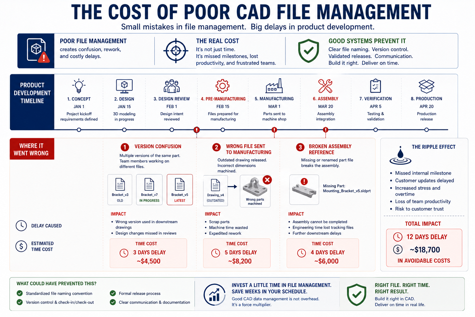
Somewhere in an engineering organization right now, a machinist is cutting a part to a drawing that was superseded three weeks ago. Somewhere else, two engineers are simultaneously editing the same assembly file, each unaware the other has it open. And somewhere, an engineer is spending their third hour this week trying to locate the correct version of a model that should have taken thirty seconds to find.
These are not isolated failures. They are the predictable outcomes of CAD file management that has not kept pace with the complexity of the team and the product. The files exist. The data is technically accessible. But without the systems, conventions, and disciplines to manage it properly, that data becomes a liability rather than an asset.
CAD file management is one of the most underinvested areas in engineering operations. Teams spend months selecting the right CAD tool and weeks on training, then leave file organization to evolve organically, which usually means chaotically. The result is a data environment where finding the right file takes longer than it should, where version errors reach production with embarrassing regularity, and where every new engineer who joins the team spends weeks just learning where things live.
This guide covers the practical systems, conventions, and decisions that transform a disorganized CAD data environment into one that accelerates engineering work rather than obstructing it. The principles apply whether your team uses SolidWorks, Creo, CATIA, Inventor, Fusion 360, or any other parametric platform, and whether you are a team of three engineers or three hundred.
Why CAD File Management Fails: The Root Causes
Before prescribing solutions, it is worth understanding exactly why CAD file management breaks down in the first place. The failure modes are consistent across organizations of every size and industry, and they almost always stem from the same set of root causes.
The Organic Growth Problem
Most engineering teams start small. In the early days, one or two engineers can keep track of everything in their heads. Files live on a shared drive organized by project, named by whoever created them, and managed through a combination of memory and informal communication. This works until it does not, and the transition from working to broken usually happens gradually enough that no one notices the moment it fails.
By the time the pain becomes acute, the organization has hundreds or thousands of files in a structure that reflects six years of organic growth rather than deliberate design. Retrofitting proper file management onto this situation is significantly harder than establishing it from the beginning, but it remains the situation most engineering teams find themselves in.
The CAD File Dependency Problem
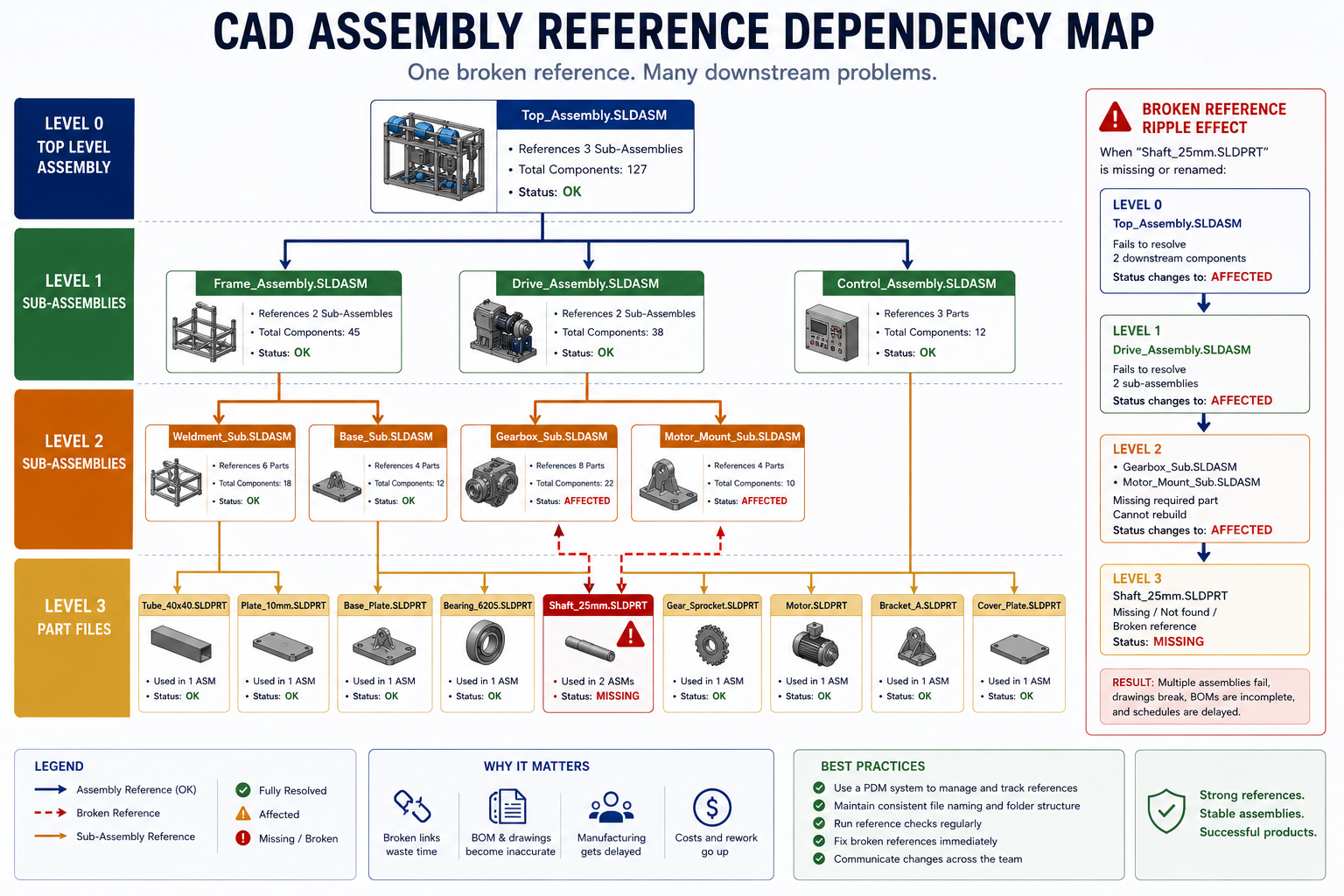
CAD files are not independent documents. A SolidWorks assembly file contains references to every part file it uses, stored as absolute or relative paths. An Inventor drawing file references the model it documents. A CATIA product structure references its component files. When any of these referenced files moves, is renamed, or is deleted, every file that references it develops a broken link and fails to load correctly.
This dependency structure makes CAD file management fundamentally different from managing ordinary documents. You cannot treat CAD files the way you treat PDF reports or Word documents, moving them around freely in Windows Explorer or copying them to a shared drive without consequences. Every file operation that happens outside the CAD software’s own file management tools carries the risk of silently breaking references throughout your entire model library.
| Critical Warning Renaming or moving CAD files using Windows Explorer, macOS Finder, or any sync tool that operates at the operating system level will break parametric assembly references. This is one of the most common and preventable sources of assembly load failures in engineering teams. Always rename and move CAD files using the tools built into your CAD software or PDM system, never through the operating system. |
The Version Proliferation Problem
Without a structured version control system, engineers solve the problem of tracking revisions the only way they can: by encoding version information in file names. This produces folders full of files with names like Housing_v3_FINAL_revised_USE-THIS-ONE.sldprt, which answer the question of which file is current exactly never. Each name makes sense to the engineer who created it at the moment they created it. Six months later, to anyone else, it is indecipherable.
The version proliferation problem compounds because people are cautious. Engineers are reluctant to delete older versions in case they need to go back, so old files accumulate alongside new ones. The folder grows. The file names grow longer and more desperate. And the probability that someone opens the wrong version and works from it for hours before noticing continues to increase.
The Onboarding Cost Nobody Measures
One of the most significant and least discussed costs of poor CAD file management is the time it takes new engineers to become productive on an unfamiliar dataset. In a well-organized, well-documented CAD data environment, a new engineer can navigate the file structure, understand the naming conventions, locate relevant models, and begin contributing meaningful work within days. In a poorly organized environment, the same process takes weeks.
This cost is rarely measured explicitly because it is diffuse: it shows up as slower output from a new hire, as questions to senior engineers that interrupt their own work, and as early errors from working with wrong or outdated files. Multiply it across every new hire and every engineer who picks up an unfamiliar project, and the cumulative cost of poor file organization becomes very significant.
The Foundation: A File Naming Convention That Actually Works
File naming is the most basic layer of CAD file management, and it is the one that most teams get wrong. A good naming convention does not just make files look organized. It encodes information that makes the right file findable, the revision level immediately visible, and the file’s role in the product structure instantly understood by anyone on the team.
The Core Principles of Effective CAD File Naming
Use part numbers, not descriptions, as the primary filename. A file named 10045-A.sldprt is unambiguous. A file named BracketMounting_revised_v2.sldprt is not. The part number uniquely identifies the component regardless of how its design evolves, what it is called colloquially, or how many revisions it goes through. The description belongs in the file properties and the drawing title block, not the filename.
Encode the revision level in the filename using a standardized format. The most common convention is a letter-based revision indicator appended to the part number: 10045-A.sldprt for revision A, 10045-B.sldprt for revision B. This makes the current revision visible without opening the file and makes it immediately clear when multiple revisions of the same part exist in a folder.
Use a consistent separator character and avoid spaces. Spaces in filenames cause problems in many engineering software environments, PDM systems, and automated workflows. Use hyphens or underscores as separators and apply them consistently across every file type: parts, assemblies, drawings, and associated documents.
A Practical Naming Convention Template
The following structure works for most mechanical engineering teams. Adapt it to your specific numbering system and organizational conventions, but maintain the principle that every element of the name carries specific, defined meaning.
CAD File Naming Convention TemplateFormat: [ProjectCode]-[PartNumber]-[Revision].[Extension]Examples: PROJ001-10045-A.sldprt (SolidWorks part, Project 001, PN 10045, Rev A) PROJ001-20012-A.sldasm (SolidWorks assembly) PROJ001-10045-A.slddrw (SolidWorks drawing) PROJ001-10045-A_STEP.step (STEP export for supplier use) PROJ001-10045-A_PDF.pdf (Drawing PDF for release)Rules: - Project code: 6-8 chars max, all caps - Part numbers: sequential, never reused for different parts - Revision: single letter, A through Z (skip I, O to avoid confusion) - No spaces, no special characters except hyphens and underscores - Part number in filename MUST match part number in drawing title block |
What to Do About Descriptive Elements
Some teams resist pure part-number filenames because they find description-based names more intuitive during daily work. A reasonable compromise is to use part numbers as the primary identifier while adding an optional short description token that is consistent and controlled. For example: 10045-BracketMount-A.sldprt. The part number remains the authoritative identifier. The description token aids quick visual recognition without creating the ambiguity that description-only names produce.
Whatever convention you choose, the critical discipline is consistency. A naming convention applied to 80 percent of files provides 20 percent of the value of one applied to 100 percent. Partial conventions create exactly the same confusion as no convention, because engineers cannot trust that the rules apply to any given file they encounter.
Folder Structure: Organizing for How Engineering Teams Actually Work
Folder structure is the second layer of CAD file organization, and it has a specific technical requirement that ordinary document management does not: it must preserve CAD assembly references. An assembly file contains paths to its component part files. How you organize your folders determines whether those paths remain valid as the project evolves and whether they survive when the project is archived or transferred to another system.
The Two Folder Structure Philosophies
Product-centric organization groups all files related to a product or project in a single folder hierarchy: parts, assemblies, drawings, specifications, and supporting documents all live under one root folder identified by the project or product name. This approach makes it easy to archive, transfer, or share an entire project because all its components travel together. It is the most common structure for teams working on discrete product programs.
Function-centric organization separates files by type: a global parts library, an assembly library, a drawings library, and so on. This structure works well when parts are reused across multiple projects, because the shared part lives in one location rather than being duplicated in each project folder. The tradeoff is that transferring a single project requires gathering files from multiple locations, which creates risk of missing components.
Most successful engineering teams use a hybrid: a product-centric primary structure with a separate, carefully controlled library for reusable standard parts, purchased components, and fasteners. The library is treated as infrastructure, managed with extra care, and referenced by all projects.
A Reference Folder Structure for Mechanical Engineering Teams
Recommended CAD Project Folder Structure |
The Archive Folder Discipline
The ARCHIVE folder in the structure above deserves specific attention. One of the most common file management failures is the accumulation of old revision files in the same location as current ones, because engineers are understandably reluctant to delete geometry that might be needed for reference. The archive folder solves this by providing a designated home for superseded revisions without cluttering the active working folders.
The archive folder should be treated as read-only once files are placed in it. Engineers can open archived files to reference them, but all active work happens in the main CAD folders using current revision files. This one discipline alone eliminates a significant fraction of the wrong-file-in-production errors that plague teams without structured version management.
| Team Discipline Note The folder structure only works if everyone uses it consistently. Establish the structure before the project starts, document it in a one-page reference guide, include it in the onboarding process for new engineers, and audit it periodically. A folder structure that 90 percent of the team follows is only marginally better than no structure, because the 10 percent of exceptions are exactly the files that will cause problems. |
Version Control: From Manual Naming to PDM Systems
Version control is the practice of tracking every revision of every file so that the history of the design is preserved, the current version is unambiguous, and previous versions can be recovered when needed. In CAD, this is not optional. It is a fundamental operational requirement for any team that expects to revise its designs, which is every team.
The Limits of Manual Version Control
Manual version control, meaning the use of file naming and folder organization to track revisions without dedicated software, can work for very small teams at early stages of a project. It requires extremely disciplined adherence to naming conventions, a clear protocol for how and when revision letters are incremented, and the self-discipline of every engineer to follow the system without exceptions.
The fundamental vulnerability of manual version control is that it has no enforcement mechanism. A single engineer who saves a file without updating the revision letter, who works on a local copy that is never synchronized back to the shared location, or who sends a supplier an attachment from their sent mail folder rather than from the controlled released folder bypasses the entire system without triggering any warning or audit trail. For teams beyond three to five engineers, or for any team where the consequences of a version error are significant, manual version control is not a sustainable approach.
Resilio
What PDM Actually Does
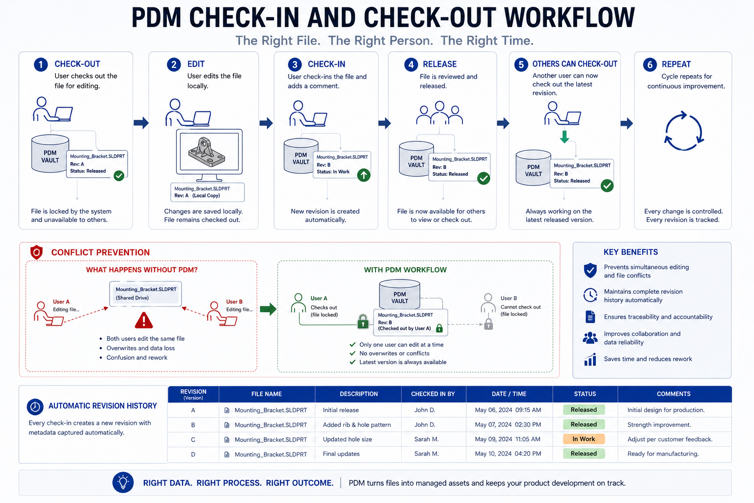
Product Data Management (PDM) is software designed specifically to manage the version control, access control, and workflow management of CAD files and related engineering data. Unlike a shared drive, a PDM system understands the dependency structure of CAD assemblies. It knows that when you check out an assembly, you may also need to check out its component parts. It maintains a complete revision history for every file. It prevents two engineers from simultaneously editing the same file. And it enforces a release workflow so that files cannot be marked as released without going through a defined approval process.
The check-in and check-out model is the core mechanism of PDM version control. When an engineer wants to modify a file, they check it out of the vault. The PDM system locks the file against editing by others while it is checked out. When the engineer is finished, they check the file back in, and the PDM system creates a new revision, preserving the previous version in the revision history. No file is ever overwritten, no revision is ever lost, and there is always a clear record of who changed what and when.
The OneDrive and Consumer Cloud Warning
A common shortcut for small engineering teams is to use consumer cloud storage services such as OneDrive, Dropbox, or Google Drive as a shared CAD repository. This approach has a specific and well-documented failure mode that makes it unsuitable for CAD data management: sync conflicts.
When two engineers have the same CAD file synced to their local machines and both make changes, the sync service creates conflict copies when it detects the divergence. In a standard document context, this is a minor inconvenience. In a CAD context, SolidWorks and other parametric CAD tools are known to experience file corruption from sync conflicts because these tools maintain external reference links and lock files during editing in ways that consumer sync services do not understand or respect. The result can range from broken assembly references to genuinely corrupted model files that cannot be recovered.
For teams that need cloud accessibility without the risks of general-purpose sync services, options include CAD-specific cloud platforms such as Onshape and Autodesk Fusion 360 (which handle version control natively in the cloud), or hosted PDM solutions that provide controlled cloud access to the vault through their own synchronization protocols.
Choosing the Right System for Your Team Size
One of the most common and costly mistakes in CAD data management is choosing a system that is either too simple for the team’s actual needs or so complex that the overhead of using it correctly exceeds its benefits. The right system is not a fixed answer. It depends on team size, project complexity, revision frequency, the number of external collaborators, and the regulatory environment.
The following table maps team size and stage to the appropriate management approach. Use it as a starting point for your own assessment, not as a rigid prescription.
| Team Size | Stage | Recommended Approach | Tools |
| 1-3 engineers | Startup / prototype | Structured local folders + strict naming convention | OS folders, manual PDF exports |
| 3-8 engineers | Early growth | Lightweight vaulting or hosted PDM | SOLIDWORKS PDM Standard, GrabCAD Workbench, Onshape |
| 8-25 engineers | Scaling product development | Full PDM with check-in/check-out and revision control | SOLIDWORKS PDM Professional, Autodesk Vault, Windchill |
| 25-100+ engineers | Multi-project, multi-site | PDM + PLM integration with ECO workflow automation | Windchill, Teamcenter, 3DEXPERIENCE, Arena PLM |
| 100+ engineers | Enterprise, regulated industries | Full PLM with ERP integration and compliance tracking | Siemens Teamcenter, Dassault 3DEXPERIENCE, SAP integration |
The Transition Points That Matter Most
The transition from shared folders to PDM is the most critical inflection point for engineering teams. Most teams delay this transition longer than they should because implementing a PDM system feels like a significant investment of time and money at a moment when the pain of the current approach is manageable. The problem is that the transition becomes harder the longer it is delayed: more files accumulate in the uncontrolled environment, more team members build habits around the old system, and the cost of migrating existing data grows.
The right moment to implement PDM is when the team reaches three to five engineers working concurrently on shared assemblies, not when version errors have already started causing production problems. Proactive implementation is significantly less expensive than reactive implementation.
The transition from PDM to PLM is appropriate when engineering data needs to flow beyond the engineering team: to manufacturing, procurement, quality, supply chain, and service. A PLM system is not just a bigger PDM. It connects engineering data to business processes across the entire product lifecycle, enabling change management workflows, BOM handoff to ERP, and compliance documentation that PDM alone cannot provide.
| Key Insight PDM is the right tool when your primary challenge is controlling engineering data within the design team. PLM is the right tool when your primary challenge is connecting engineering data to every other function that needs it throughout the product’s life. Many teams need both: PDM as the day-to-day engineering environment and PLM as the enterprise coordination layer. |
Managing Assembly References: The Most Technically Demanding Part of CAD File Management
For engineering teams working with complex parametric assemblies, managing file references is where CAD file management becomes genuinely technical. Assembly references are the links that hold a multi-body model together. Managing them incorrectly is one of the most common causes of catastrophic file failures in engineering organizations.
How Assembly References Work
When you insert a part into an assembly in SolidWorks, CATIA, Creo, or Inventor, the assembly file stores the path to that part file. The path is typically absolute (the full file system path from the root) or relative (the path from the assembly file’s location). Every time you open the assembly, the CAD software follows each stored path to find and load the component files.
If any component file has been moved, renamed, or deleted since the assembly was last opened, the path no longer leads to a valid file and the assembly cannot resolve that component. The result is a missing reference error: the component either disappears from the assembly, is replaced by a placeholder, or causes the entire assembly to fail to open depending on the CAD software and its reference resolution settings.
The Windows Explorer Rename Trap in Detail
This specific failure is worth addressing with extra clarity because it catches so many teams off guard. In Windows Explorer, renaming a file appears to be a completely safe and reversible operation. But for a CAD part file that is referenced by one or more assembly files, renaming it through Windows Explorer breaks every one of those references instantly.
The assembly files still contain the old filename in their stored paths. The CAD software cannot find the file under its new name. The assemblies fail to load their component. The only resolution is to manually re-establish each broken reference, which in a large assembly with many affected files can take hours.
The correct procedure is always to use the rename and move tools within your CAD software or PDM system. SolidWorks has a Pack and Go tool and a Rename function in its file management utilities. Creo has its own file management interface. PDM systems like SOLIDWORKS PDM Professional handle renames and moves automatically, updating all stored references across the vault whenever a file is renamed. Never use operating system file management tools for operations on files that are referenced by CAD assemblies.
Relative vs. Absolute Reference Paths
Absolute paths (for example: C:\Engineering\Projects\PROJ001\CAD\Parts\10045-A.sldprt) specify the exact location of a file on a specific machine or network drive. They work reliably as long as the drive letter and folder structure never change, which they frequently do when projects are archived, transferred, or opened on different machines.
Relative paths (for example: ..\Parts\10045-A.sldprt) specify the location of a file relative to the location of the assembly file that references it. As long as the folder structure within the project remains consistent, relative paths work correctly regardless of where the project root folder sits on the file system. This makes them significantly more portable and more suitable for projects that will be archived, transferred, or worked on across multiple machines.
Most PDM systems manage reference paths transparently, abstracting away the file system path entirely and using internal database identifiers instead. This is one of the practical advantages of PDM over manual folder management: reference integrity is maintained by the system regardless of where files physically sit on the storage infrastructure.
Revision Control and the Engineering Change Process
Version control tracks every edit to every file. Revision control is a more formal layer on top of it: the process of formally incrementing and documenting a design change so that there is a clear, auditable record of what changed, why it changed, who approved the change, and what the impact was on downstream files, drawings, and procured parts.
These two concepts are often conflated, but the distinction matters. You can have excellent version control through a PDM system while having no formal revision control process, and the result is a complete history of every file save with no way to understand which changes were significant, which were approved, and which are reflected in production parts.
Engineering Change Orders and Their Connection to CAD Data
An Engineering Change Order (ECO) or Engineering Change Notice (ECN) is the formal document that authorizes and records a design change. It specifies the part or assembly being changed, the nature of the change, the reason, the impact assessment, and the signatures of everyone who approved it. The ECO is the business record of the change. The PDM revision history is the technical record. Both are needed.
The connection between ECOs and CAD file management is direct: when an ECO is approved, the relevant CAD files must be revised and the new revision released into the controlled environment in a way that supersedes the previous revision. Drawings must be updated to reflect the revision letter. Bills of materials that reference the changed part must be updated. And suppliers who hold drawings or models of the part must be notified and provided with updated documentation.
Managing all of this manually is error-prone and slow. PLM systems are specifically designed to automate and enforce this workflow, but even without a PLM, a clearly defined manual ECO process that includes explicit steps for updating CAD data, releasing new drawings, and notifying suppliers will prevent most of the version errors that reach manufacturing.
Read related article on: How Design Tables Speed Up Product Development
Release States: The Key to Controlling What Goes to Manufacturing
One of the most powerful features of a PDM or PLM system is the ability to assign release states to files. Common states include Work in Progress, Under Review, Released, and Obsolete. Files in the Released state are locked against further modification without initiating a formal change process. Only Released files can be transmitted to manufacturing or procurement.
This state-based control closes the gap that manual version control leaves wide open: in a shared folder environment, there is nothing to prevent an engineer from sending a Work in Progress drawing to a supplier by accident, because there is no system-enforced distinction between files that are ready for release and files that are not. With state-based PDM control, the distinction is structural rather than procedural, which means it works even when engineers are in a hurry.
Multi-Site and Multi-Supplier CAD Data Management
For engineering teams that work across multiple offices, collaborate with contract engineering firms, or regularly exchange CAD data with suppliers and customers, file management introduces a layer of complexity that single-site, single-team approaches do not address. The core challenge is maintaining a single source of truth for design data when multiple parties need access to it from different locations, using different CAD tools, and with different levels of data access authorization.
The Single Source of Truth Imperative
Single source of truth means that there is one authoritative location for every piece of design data, and every team member, supplier, and partner who needs that data accesses it from that single location rather than from their own local copy. In a multi-site environment, maintaining this principle requires deliberate architecture: either a central server with controlled remote access, a hosted PDM vault with synchronization to satellite offices, or a cloud-based PLM that provides access to all authorized parties through a browser or client application.
When the single source of truth breaks down, which happens whenever teams maintain local copies that drift out of sync with the central repository, the result is the multi-version problem at scale. Teams in different locations may be working from different versions of the same assembly. A change made at headquarters may not propagate to the contract engineering firm for days. A supplier may be quoting from a model that was superseded two ECOs ago.
Controlling What Suppliers Receive
Supplier data management is one of the most consistently under-engineered aspects of CAD file management. The common practice of emailing STEP files and PDF drawings to suppliers is fragile by design: there is no tracking, no confirmation of which revision was received, no mechanism for notifying the supplier when a revision changes, and no way to prevent the supplier from continuing to use an outdated file after a revision has been issued
Better practice involves transmitting supplier data only through a controlled release process: a formal transmittal document that lists every file being sent, the revision level of each, and the purpose of the transmittal. The transmittal is logged in the project record along with confirmation of receipt. When a revision changes, a new transmittal is issued and the supplier is explicitly asked to confirm they have replaced the previous revision.
For suppliers who are integrated deeply into the design process, collaborative PDM or PLM platforms that provide suppliers with controlled, view-only or limited-edit access to specific project data eliminate the transmittal overhead entirely while providing even stronger version control than manual transmittals can achieve.
CAD Data Exchange Formats for External Collaboration
- STEP (ISO 10303): The most universal neutral exchange format for 3D geometry. Preserves solid body geometry and color information but not parametric history. Use for most supplier communication.
- IGES: An older neutral format, still widely supported but increasingly superseded by STEP for new work. Useful for legacy systems that do not support STEP.
- PDF with embedded 3D (PDF/A with 3D annotation): Useful for sharing models with parties who need to view but not edit geometry. Preserves drawing annotations alongside 3D geometry.
- Native CAD formats: Transmit only when contractually required or when the recipient uses the same CAD tool. Transmitting native files exposes internal parameters, modeling logic, and proprietary design decisions.
Backup, Recovery, and Long-Term Archiving
CAD data represents hundreds or thousands of hours of engineering work. Losing it to a hardware failure, ransomware attack, or accidental deletion is a business-level event, not just an IT inconvenience. Despite this, backup strategies for CAD data are frequently inadequate, partly because the large file sizes and complex dependency structures of CAD datasets make them more difficult to back up correctly than ordinary files.
The 3-2-1 Backup Principle for CAD Data
3-2-1 backup means: three copies of the data, on two different media types, with one copy off-site. Applied to CAD data: the primary working copy in the PDM vault or shared drive, a local backup on a separate NAS device or backup server, and a cloud or off-site backup that is geographically separated from the primary location.
The critical requirement for CAD backups that is often overlooked is that the backup must capture the entire dependency graph, not just individual files. Backing up only the assembly file without its component parts produces a backup that cannot be opened. A complete project backup must include every part file, every drawing file, every configuration file, and every referenced document that the assembly depends on. PDM systems simplify this by allowing entire vault backups that capture all data and all relationships simultaneously.
Testing Backups: The Step Most Teams Skip
A backup that has never been tested is not a backup. It is a hypothesis. Backup systems fail in specific and non-obvious ways: files are backed up but cannot be restored, backup jobs report success while missing certain file types, incremental backups build on a corrupted base without flagging the problem, or the restoration process assumes software or configuration that is no longer in place.
Schedule a full restoration test at least once per quarter. Select a random sample of project data, restore it to a clean test environment, open the assembly in the CAD tool, and verify that all references resolve and all files are intact. This test takes a few hours per quarter and provides genuine confidence in the backup. Skipping it means you will not discover that the backup does not work until you need it.
Long-Term Archiving for Product Lifecycle Compliance
For companies in regulated industries such as aerospace, medical devices, defense, and automotive, CAD data must be retained in an accessible and verifiable state for the life of the product and often beyond. This is a different requirement from backup: it is about maintaining a complete, auditable record of the design data that existed at the time each product was manufactured.
Long-term archiving requires a strategy for maintaining file accessibility as software versions evolve. A SolidWorks 2015 file opened in SolidWorks 2026 may have minor differences due to solver updates. An archived file that was exported to neutral format (STEP, PDF) at the time of manufacture provides a format-independent record that does not depend on CAD software backward compatibility. For regulated products, archiving both the native CAD files and neutral format exports at each production release is the most defensible approach.
| Compliance Note In aerospace (AS9100), medical devices (ISO 13485), and automotive (IATF 16949) quality management systems, design history records including CAD data must be maintained for specified periods that often extend well beyond the product’s active production life. Your CAD file management system must be designed to support this requirement, including the ability to demonstrate what revision of a design was current at any specific point in time. |
Building a CAD File Management Culture, Not Just a System
Systems and tools are necessary but not sufficient. The most sophisticated PDM system delivers poor results if engineers route around it, and the simplest naming convention delivers excellent results if every engineer follows it without exception. CAD file management ultimately depends on human discipline applied consistently, and that requires cultural investment as much as technical investment.
Making the Right Behavior the Easy Behavior
The most effective way to ensure compliance with file management standards is to design the system so that the correct behavior is also the easiest behavior. If checking a file into the PDM system is faster and simpler than saving it to a personal desktop folder, engineers will check it in. If the folder structure makes it faster to find a file than searching through a personal downloads folder, engineers will use the folder structure.
Friction in the correct workflow is the enemy of compliance. Audit your file management process for points where doing the right thing requires extra steps, and eliminate those steps wherever possible. A five-second check-in process will be used consistently. A three-screen approval workflow for a routine revision will be routinely bypassed.
Onboarding: Where File Management Culture is Established or Lost
The most important moment to establish file management culture with a new engineer is in their first week. If the first project they work on has a clear, well-organized file structure with a documented naming convention and a working PDM system, they will internalize these as the normal state of affairs. If their first experience is of a chaotic shared drive with no discernible organization, they will adapt to that chaos and perpetuate it.
Build file management standards into the engineering onboarding process explicitly. Provide a one-page reference document covering the naming convention, folder structure, and PDM workflow. Walk through a real example of the check-in and check-out process. Explain where the archive folder is and how to use it. This investment of an hour in onboarding prevents weeks of confusion and incorrect file management over the course of the engineer’s tenure.
Periodic Audits: Keeping the System Honest
Even well-designed systems drift over time as team members develop shortcuts and as the pressure of project deadlines creates exceptions that quietly become norms. Schedule a periodic audit of your CAD file management practices, quarterly for active teams, semi-annually for more stable ones. The audit should check:
- Whether the naming convention is being applied consistently to all new files
- Whether the folder structure is being maintained or whether ad-hoc folders are proliferating
- Whether the archive folder contains all superseded revisions or whether old files are accumulating in active folders
- Whether PDM check-out and check-in workflows are being followed or whether engineers are directly editing files in the vault
- Whether supplier transmittals are being logged and tracked
- Whether backup restoration tests have been completed on schedule
The audit is not a policing exercise. It is a diagnostic tool that identifies where the system has gaps and where additional training or process improvement is needed. Treat findings as opportunities to improve the system rather than as individual failures.
Frequently Asked Questions
Q: What is the best way to name CAD files for a small engineering team?
Use part numbers as the primary filename component rather than descriptive names. A format like [ProjectCode]-[PartNumber]-[Revision].[extension] is unambiguous, scales as the team grows, and integrates cleanly with PDM systems when you implement them. Avoid spaces, avoid special characters except hyphens and underscores, and apply the convention consistently to every file from day one.
Q: Why do CAD assembly files lose their references when files are moved?
CAD assembly files store the locations of their component parts as file paths. When a part file is moved or renamed using operating system tools like Windows Explorer, the stored path no longer points to a valid file location and the assembly cannot find the component. Always use the rename and move tools within your CAD software or PDM system, which update all stored references automatically when a file is relocated.
Q: When should an engineering team implement a PDM system?
Implement PDM when your team reaches three to five engineers working concurrently on shared assemblies, or earlier if you are in a regulated industry where design data control is a compliance requirement. The cost of PDM implementation is significantly lower than the cost of the version errors, lost files, and rework that occur without it. The longer you wait past this threshold, the more expensive the transition becomes.
Q: What is the difference between PDM and PLM?
PDM (Product Data Management) focuses on managing CAD files and engineering documents within the design team: version control, check-in and check-out, revision history, and access control. PLM (Product Lifecycle Management) extends this to cover the entire product lifecycle across all departments: manufacturing, procurement, quality, supply chain, and service. PDM manages the files. PLM manages the product and all the business processes around it.
Q: Is it safe to store CAD files in OneDrive or Google Drive?
Consumer cloud sync services are not recommended for CAD file storage for professional engineering use. SolidWorks and other parametric CAD tools are known to experience file corruption from sync conflicts when two users have the same file synced locally and edit it simultaneously. For cloud CAD data management, use CAD-native cloud platforms such as Onshape or Autodesk Fusion 360, or hosted PDM solutions that manage synchronization through controlled protocols designed for CAD data.
Q: How should engineering teams handle CAD data exchange with suppliers?
Use formal transmittal documents that record every file sent, its revision level, and the date of transmission. Send only controlled neutral format exports (STEP, PDF) rather than native CAD files unless contractually required. Confirm receipt and revision acknowledgment with the supplier. Issue new transmittals whenever a revision changes and explicitly request that suppliers retire the previous revision. For deeply integrated suppliers, consider a collaborative PDM or PLM platform that gives them controlled, audited access to released data.
Q: How long should CAD files be retained after a product is discontinued?
Retention requirements depend on your industry and applicable regulations. For aerospace (AS9100) and medical devices (ISO 13485), design records are typically required for the life of the product plus a specified period, often ten years or more after the last manufactured unit. For automotive (IATF 16949), requirements vary by customer. In unregulated industries, a practical minimum is to retain all CAD data for the warranty period of the product plus a reasonable buffer. Consult your legal and quality teams to establish the specific requirement for your products.
Conclusion:
A CAD model that cannot be found is worth nothing. A drawing released without version control is a liability. An assembly that loses its references every time a file is moved is a time bomb. These are not hypothetical risks. They are the daily reality of engineering teams whose file management practices have not kept pace with the complexity of what they are designing.
The investment required to fix this is smaller than the cost of not fixing it. Establishing a clear naming convention takes an afternoon. Setting up a logical folder structure takes a day. Implementing a lightweight PDM system for a small team takes a week. And the cumulative time saved by eliminating version errors, wrong-file manufacturing events, and broken reference debugging pays back that investment within the first program cycle.
Start with the practice that will have the highest immediate impact for your specific team. If version errors are your primary pain, focus on naming conventions and archive discipline first. If broken assembly references are costing you hours, invest in understanding and fixing your reference path strategy. If manual version tracking has become unsustainable, evaluate PDM options now, not after the next production error.
The engineering work your team does is valuable. The CAD data that captures it is the tangible record of that value. Managing it with the same rigor you apply to the engineering itself is not overhead. It is how you protect and leverage the investment your team makes every day.
Looking to tighten up your full CAD workflow? Explore our guides on design intent, parametric modeling best practices, avoiding CAD rework, and DFM for manufacturing.