Tag: Cad software

  • Best CAD Software for Engineers: 2026 Complete Guide

    Best CAD Software for Engineers: 2026 Complete Guide

    Choosing the best CAD software for engineers is one of the most consequential technical decisions a professional, a team, or a company makes. The wrong choice does not just cost money, it costs time, efficiency, compatibility, and career development. Switching between major CAD platforms mid-career or mid-project is painful and expensive. Getting the decision right from the start matters.

    The problem is that most CAD software comparison guides are either too generic (a list of tools with brief descriptions), too narrow (focused on one engineering discipline), or openly biased (written by a CAD vendor or a site earning commission on software referrals). None of them answer the questions engineers actually need answered: Which CAD tool is dominant in my specific industry? What does it actually cost for a small team? Which tools will make me more employable? When does it make sense to use free software rather than paid? What does each tool genuinely do badly?

    This guide answers all of those questions honestly. It covers the 10 most important CAD software tools for engineers in 2026, with an industry-specific recommendation matrix across 8 engineering disciplines, a verified pricing comparison table, an honest assessment of each tool’s weaknesses alongside its strengths, career and job market data, a free vs paid decision guide, and a full FAQ section. No affiliate links. No vendor influence. Just the data.

    Quick Recommendations by Use Case:  Mechanical/product design: SolidWorks (mid-market) or CATIA/NX (enterprise). 2D drafting and documentation: AutoCAD. Startups and budget-conscious teams: Fusion 360. Aerospace and automotive: CATIA or Siemens NX. Civil and infrastructure: AutoCAD Civil 3D or Bentley MicroStation. Free alternative: FreeCAD or Onshape (free tier). The full guide below explains why.

    How to Choose CAD Software: The Four Deciding Factors

    Before evaluating individual tools, clarifying four fundamental factors eliminates most of the complexity in choosing CAD software for engineers. Most engineers who end up with the wrong tool failed to prioritise these questions before starting their evaluation.

    Factor 1: Industry and Employer Standard

    The single most important factor is not which CAD tool is objectively best, it is which tool dominates your target industry and the employers you want to work for. Aerospace companies overwhelmingly use CATIA or NX. Automotive OEMs use CATIA, NX, or Creo depending on geography. Most mechanical engineering product development companies use SolidWorks. Civil and infrastructure projects use AutoCAD Civil 3D or Bentley. Knowing your industry’s standard tool and prioritising proficiency in it is the most career-efficient approach in almost every case.

    Factor 2: 2D Documentation vs 3D Parametric Modelling vs Both

    Many engineers, particularly those working in construction, infrastructure, or traditional manufacturing, primarily need 2D technical drawing and documentation capability. For them, AutoCAD or AutoCAD LT is sufficient and appropriate. Engineers involved in product development, component design, or manufacturing process design almost always need 3D parametric modelling capability (SolidWorks, Fusion 360, NX, CATIA, Creo). Some roles require both, in which case AutoCAD for documentation combined with a parametric 3D tool for modelling is a common workflow.

    Factor 3: Team Size and Budget

    CAD software costs vary by a factor of 20 to 30 across the tools in this guide. Enterprise tools (CATIA, NX) are priced at $10,000 to $80,000+ per seat per year and are designed for large engineering organisations with IT infrastructure, PLM integration, and dedicated CAD administration. They deliver exceptional value at scale but are completely impractical for individuals or small teams. Mid-market tools (SolidWorks, Creo, Inventor) are priced at $2,000 to $10,000 per seat per year. Accessible tools (Fusion 360, Onshape) are priced at $500 to $2,000 per seat per year and are available free for qualifying users. Matching the tool to the budget reality is as important as matching it to the technical requirement.

    Factor 4: Collaboration Model (Desktop vs Cloud)

    Traditional desktop CAD tools (AutoCAD, SolidWorks, CATIA, NX, Creo) require local installation and a dedicated hardware workstation. They offer maximum performance and the most mature feature sets, but file sharing and version control require PDM/PLM infrastructure. Cloud-native tools (Onshape, Fusion 360, Shapr3D) store all data in the cloud and allow real-time collaboration without additional infrastructure. They work on any modern computer and allow mobile access. The trade-off is that they require reliable internet connectivity and have some limitations in handling very large assemblies or complex simulations compared to desktop tools.

    CAD Software Pricing Comparison Table 2026

    The following pricing data is sourced from official vendor pricing pages and publicly available subscription information as of 2026. Enterprise pricing for CATIA and NX is highly variable based on contract size and varies significantly by configuration, ranges are indicative only.
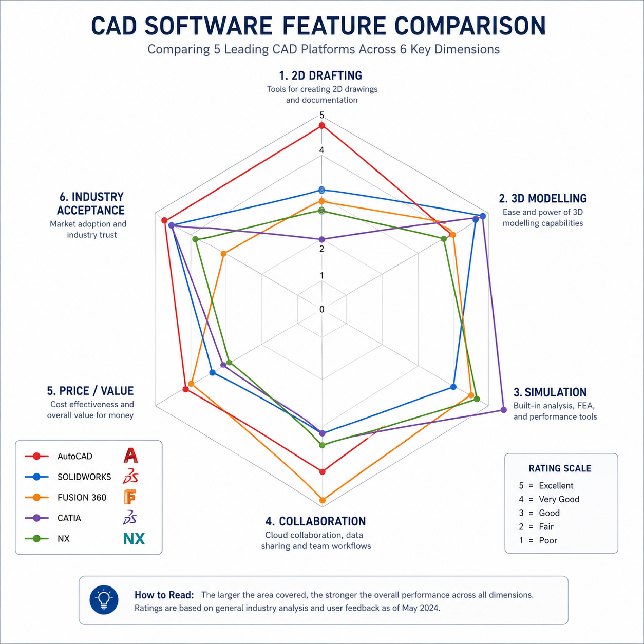
    CAD software comparison radar chart comparing AutoCAD SolidWorks Fusion 360 CATIA and Siemens NX across 2D drafting 3D modelling simulation collaboration price and industry acceptance
    CAD SoftwareEntry Price (per seat/year)Full ProfessionalStudent / EducationFree Tier Available?Deployment
    AutoCAD$2,230/year or $195/monthSame (single product)Free via Autodesk Education30-day trialDesktop + Web + Mobile
    AutoCAD LT$570/year or $55/monthSame (2D only)Free via Autodesk Education30-day trialDesktop + Web
    SolidWorks (Standard)~$2,620/year (subscription)SolidWorks Premium ~$5,500+/yearSOLIDWORKS for Students (low cost)No (trial only)Desktop
    Autodesk Fusion 360$545/year (Personal/Startup)~$795/year (commercial)Free for students/educatorsYes, personal/startup free tierCloud + Desktop
    CATIA (3DEXPERIENCE)$10,000-$80,000+/year (enterprise, varies)Configured per enterprise contractAcademic access via institutionsNoDesktop + Cloud (3DX)
    Siemens NX$8,000-$70,000+/year (enterprise, varies)Configured per enterprise contractNX for Students (free)No (30-day trial)Desktop
    PTC Creo$2,500-$15,000+/year (varies by module)Creo Advanced or UltimatePTC Education licenceNo (30-day trial)Desktop
    Autodesk Inventor$2,545/year (subscription)Included in Product Design SuiteFree via Autodesk Education30-day trialDesktop
    Onshape$1,500/year (Standard)Professional: $2,100/yearFree for students/educatorsYes, free public planCloud-native (browser)
    Bentley MicroStation~$3,500/year (subscription)Enterprise via Bentley contractAcademic/student licences availableNoDesktop
    FreeCADFree (open source)Free (open source)FreeYes, fully freeDesktop (cross-platform)
    Note: Pricing is indicative based on publicly available information as of 2026. Enterprise contracts for CATIA, NX, and Creo are negotiated individually and typically include volume discounts, support, training, and PLM integration. Always verify current pricing directly with vendors before budgeting.

    Industry-Specific Recommendation Matrix

    This matrix reflects real industry adoption data based on job posting frequency, employer survey data, and engineering community usage patterns as of 2026. The Primary Tool is the tool most commonly required by employers in that sector. The Secondary Tool is a strong alternative or complement.
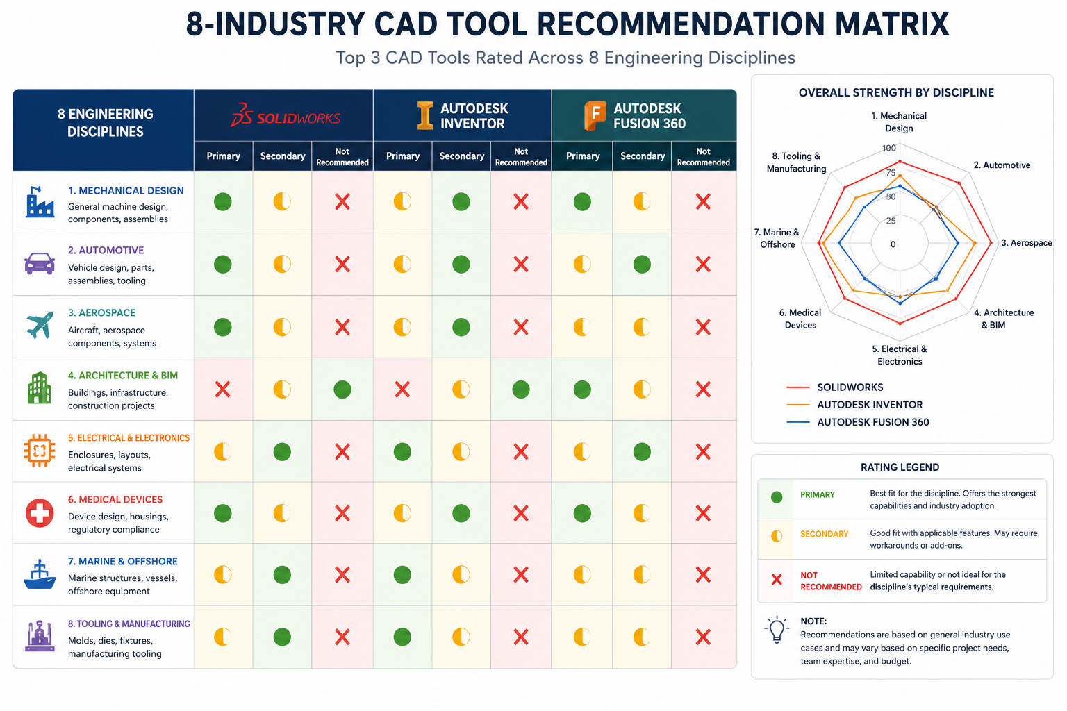
    CAD software recommendation matrix for engineers by industry showing AutoCAD SolidWorks CATIA Fusion 360 NX suitability across 8 engineering disciplines
    Engineering DisciplinePrimary CAD ToolSecondary ToolWhy This Tool DominatesKey Reason to Learn It
    Mechanical / Product DesignSolidWorksAutodesk Inventor or Fusion 360Market-leading parametric 3D tool for product development. Required in over 65% of mechanical engineering job postings.Most in-demand parametric CAD skill globally for mid-market mechanical engineering roles
    Aerospace and DefenceCATIA (Dassault)Siemens NXAirbus, Boeing, Dassault Aviation, and most global aerospace OEMs standardise on CATIA or NX. Deep surface modelling and systems engineering capability.Essential for careers in commercial aerospace, space vehicles, and high-end defence engineering
    Automotive (OEM)CATIA or Siemens NXCreo (PTC)European and Asian OEMs (BMW, VW, Toyota) use CATIA; GM uses NX. Body-in-white, surface design, and digital mockup drive tool selection.Automotive OEM and Tier 1 supplier roles require enterprise CAD proficiency
    Civil and InfrastructureAutoCAD Civil 3DBentley MicroStationAutoCAD Civil 3D dominates road, drainage, and site design. Bentley is the standard in large-scale infrastructure (rail, highways, utilities).Most civil engineering employers require AutoCAD proficiency at minimum
    Architecture and Construction (MEP)AutoCAD / RevitAutoCAD MEP toolsetAutoCAD for documentation; Revit for BIM coordination. HVAC engineers use AutoCAD MEP toolset or MicroStation.AutoCAD is baseline; Revit adds BIM value for coordination roles
    Structural EngineeringAutoCAD / Tekla StructuresSolidWorks (for steel connections)Structural steelwork: Tekla Structures dominant. Reinforced concrete detailing: AutoCAD widely used.AutoCAD proficiency expected; Tekla adds specialist steel detailing value
    Electrical EngineeringAutoCAD ElectricalEPLAN (not CAD per se, but dominant)AutoCAD Electrical toolset for wiring diagrams, panel layouts, and schematics is the primary choice for electrical designers.AutoCAD Electrical is the most employer-requested electrical CAD tool
    Manufacturing EngineeringSolidWorks or Fusion 360Siemens NX (with CAM)Product design uses SolidWorks; CNC machining benefits from Fusion 360’s integrated CAM. Process-heavy manufacturing uses NX.Fusion 360’s CAD+CAM integration is uniquely valuable for manufacturing engineers who also oversee machining

    Tool 1: AutoCAD, The Universal Standard for Documentation

    AutoCAD has been the global standard for technical drawing and documentation for over 40 years, and in 2026 it remains the most widely deployed CAD software in the world by active users. Its DWG file format is the universal language of engineering drawings, readable by virtually every other CAD system ever made.

    What AutoCAD Does Best

    • 2D technical drafting: No other tool matches AutoCAD for 2D drawing production speed, precision, and compatibility across disciplines.
    • Drawing documentation and annotation: Dimensions, tables, text, hatching, and plotting workflows are more mature than any competing platform.
    • Universal compatibility: DWG file format compatibility with every other CAD tool, CNC machine, fabricator, and engineering system.
    • Industry toolsets: The AutoCAD subscription includes specialist toolsets for Architecture, Mechanical, Electrical, Civil, MEP, Plant, and Map 3D at no extra cost.

    Where AutoCAD Falls Short

    • 3D parametric modelling: AutoCAD’s 3D solid modelling is functional but non-parametric. It cannot match SolidWorks or Fusion 360 for feature-based part design or assembly management.
    • Simulation and analysis: No built-in FEA or CFD capability. Engineers needing simulation must use separate tools (ANSYS, SolidWorks Simulation, Fusion 360 Simulation).
    • Cost: At $2,230/year, AutoCAD is expensive for 2D-only work when AutoCAD LT ($570/year) or free alternatives may suffice.
    Best For:  Civil engineers, architects, structural detailers, electrical designers, MEP engineers, manufacturing documentation engineers, and any professional whose primary output is 2D technical drawings. The single most employable CAD skill across the broadest range of engineering disciplines.

    Tool 2: SolidWorks, The Mechanical Engineering Workhorse

    SolidWorks by Dassault Systemes is the dominant parametric 3D CAD tool in the mid-market mechanical engineering sector. It holds approximately 30 percent of the global CAD market by paid seats and is the most frequently required 3D CAD skill in mechanical engineering job postings globally.

    What SolidWorks Does Best

    • Feature-based parametric 3D modelling: SolidWorks’ parametric modelling engine is mature, stable, and highly efficient for mechanical component design. Changes propagate automatically through part, assembly, and drawing.
    • Assembly management: Large assembly tools (SpeedPak, Lightweight mode, Assembly Visualize) allow engineers to work with complex multi-component products efficiently.
    • Integrated simulation (SolidWorks Simulation): FEA structural analysis, fluid flow, thermal analysis, and drop test simulation are available as integrated add-ons, reducing the need for separate simulation tools.
    • Sheet metal and weldment design: Dedicated sheet metal and weldment workflows are among the best in class for manufacturing-focused mechanical engineers.
    • Ecosystem depth: PDM (Product Data Management), Inspection, Plastics, and Electrical add-ons provide a comprehensive product development platform.

    Where SolidWorks Falls Short

    • Cost for small teams: At ~$2,620/year per seat for Standard, SolidWorks is not the most budget-friendly option for freelancers or very small teams. Fusion 360 provides substantial capability at a fraction of the cost.
    • Cloud and collaboration: Traditional desktop-first architecture. Real-time collaboration requires additional PDM/PLM infrastructure investment.
    • Surface modelling for Class A surfaces: SolidWorks’ surfacing tools are good but not as sophisticated as CATIA or NX for consumer product aesthetics and Class A automotive surfaces.
    • 3DEXPERIENCE transition: Dassault’s push toward the 3DEXPERIENCE platform (cloud-based SolidWorks) has created some user confusion and concerns about transition costs.
    Best For:  Mechanical engineers, product designers, manufacturing engineers, tooling designers, R&D engineers in product development companies, and any engineer whose primary work involves 3D mechanical component and assembly design at the mid-market level.

    Tool 3: Autodesk Fusion 360, Best All-in-One for Smaller Teams

    Autodesk Fusion 360 occupies a unique and increasingly important position in the CAD market: it is the only platform that provides integrated 3D CAD, CAM (computer-aided manufacturing), CAE (simulation), electronics PCB design, and generative design in a single cloud-based subscription, at a price point accessible to startups, small businesses, and individual engineers.

    What Fusion 360 Does Best

    • Integrated CAD + CAM: Fusion 360 is the most capable integrated CAD+CAM platform available at its price point. Engineers who both design components and programme their machining (CNC routing, turning, milling) in a single workflow gain significant productivity advantages.
    • Generative design: Fusion 360 includes generative design tools that use AI to explore optimised geometries based on engineering constraints, a capability that typically requires much more expensive enterprise software.
    • Cloud collaboration: All project data lives in Autodesk cloud. Team members can access, view, and comment on designs from any device without PDM infrastructure.
    • Price-to-capability ratio: At ~$545/year (or free for qualifying personal/startup use), Fusion 360 provides more integrated capability than any comparable subscription at this price.

    Where Fusion 360 Falls Short

    • Large assembly performance: Fusion 360 struggles with assemblies above ~1,000 components compared to desktop tools like SolidWorks or NX.
    • Industry acceptance: Fusion 360 is well-accepted in manufacturing, consumer products, and startups, but is rarely seen in aerospace, automotive OEM, or large industrial engineering environments where enterprise tools are mandated.
    • Offline capability: While Fusion 360 can work offline, its cloud-dependency means reduced functionality without internet access.
    • Drawing documentation maturity: Fusion 360’s 2D drawing creation is improving but still less mature than AutoCAD or SolidWorks for complex drawing documentation.
    Best For:  Startups, product development startups, small manufacturing businesses, engineers who both design and machine parts, hobbyists and makers wanting professional-grade tools, and engineers in roles where CAD+CAM integration is more valuable than enterprise assembly management.

    Tool 4: CATIA, Enterprise Aerospace and Automotive Standard

    CATIA (Computer-Aided Three-Dimensional Interactive Application) by Dassault Systemes is the most powerful and comprehensive CAD platform in the world for complex surface modelling, large-scale assembly management, and systems engineering. It is the primary CAD tool at Airbus, Boeing (partially), Dassault Aviation, Renault, PSA Peugeot-Citroen, and dozens of other major aerospace and automotive OEMs.

    What CATIA Does Best

    • Class A surface modelling: CATIA’s FreeStyle and Generative Shape Design workbenches are the gold standard for creating mathematically perfect curvature-continuous surfaces for aerospace exteriors, automotive body panels, and premium consumer products.
    • Large-scale digital mockup: CATIA handles assemblies of tens of thousands of components (entire aircraft or vehicle programs) efficiently through dedicated DMU Navigator and interference checking tools.
    • Knowledge-based engineering (KBE): CATIA’s product knowledge base and engineering rules engine allow companies to encode design standards, automate repetitive design tasks, and ensure design compliance at scale.
    • Systems engineering (SysML/MBSE): Through 3DEXPERIENCE platform integration, CATIA supports model-based systems engineering for complex multidisciplinary products.

    Where CATIA Falls Short

    • Cost and accessibility: CATIA is priced for large enterprises and is effectively inaccessible to individuals, small businesses, or companies without a significant CAD budget. Student access is limited.
    • Learning curve: CATIA has the steepest learning curve of any mainstream CAD tool. The workbench-based interface and the breadth of modules require significant dedicated training investment.
    • Overkill for most mechanical engineering: For the vast majority of mechanical engineering work, CATIA’s power is far beyond what is needed and its complexity is a productivity cost rather than a benefit.
    Who Should NOT Use CATIA:  Small and medium-sized engineering businesses, individual engineers, and anyone outside aerospace, automotive OEM, or complex industrial systems engineering. SolidWorks provides 90 percent of CATIA’s utility for typical mechanical engineering at a fraction of the cost and complexity.

    Tool 5: Siemens NX, The High-End Manufacturing Platform

    Siemens NX (formerly Unigraphics NX) is Siemens Digital Industries Software’s flagship CAD/CAM/CAE platform, competing directly with CATIA at the enterprise end of the market. NX is the CAD standard at General Motors, BMW, Volkswagen (partially), Lockheed Martin, and many Tier 1 automotive suppliers.

    What Siemens NX Does Best

    • Integrated CAD/CAM/CAE at scale: NX provides seamlessly integrated 3D design, advanced manufacturing programming, and simulation within a single platform, eliminating the file translation issues that occur when using separate tools for each stage.
    • Advanced manufacturing: NX CAM is one of the most powerful and widely used CNC programming environments for 5-axis machining, turning, and EDM in high-precision manufacturing.
    • Convergent modelling: NX’s Convergent Modelling technology allows engineers to work directly with mesh (scan) data alongside B-rep models, useful for reverse engineering and as-built modelling.
    • PLM integration (Teamcenter): NX integrates natively with Siemens Teamcenter PLM, the most widely deployed PLM system in manufacturing industry.
    Best For:  Automotive OEM and Tier 1 suppliers, precision manufacturing companies, aerospace and defence companies using Siemens infrastructure, and large industrial equipment manufacturers requiring integrated CAD-CAM-PLM workflows.

    Tool 6: PTC Creo, Strong in Industrial and IoT Engineering

    PTC Creo (formerly Pro/ENGINEER) is PTC’s parametric 3D CAD platform, historically strong in industrial machinery, consumer products, and medical devices. Creo is particularly notable for its advanced surfacing capabilities, its model-based definition (MBD) tools, and its ThingWorx IoT integration for smart connected products.

    What Creo Does Best

    • Industrial machinery and heavy equipment: Creo’s robust assembly management and mechanism simulation tools make it particularly well-suited for complex industrial machinery design.
    • Model-Based Definition (MBD): Creo’s MBD tools for embedding 3D annotations (GD&T, tolerances, surface finish) directly in the 3D model as replacements for 2D drawing views are among the most mature in the industry.
    • IoT and smart product design: Creo’s integration with PTC’s ThingWorx IoT platform is unique among CAD tools, allowing engineers to design products and their IoT connectivity simultaneously.
    Best For:  Industrial machinery, heavy equipment, oil and gas equipment, medical devices, and companies with existing PTC Windchill PDM infrastructure.

    Tool 7: Autodesk Inventor, SolidWorks Alternative Within the Autodesk Ecosystem

    Autodesk Inventor is Autodesk’s parametric 3D mechanical CAD tool, occupying a similar market position to SolidWorks but with the advantage of native compatibility with AutoCAD DWG files and the rest of the Autodesk product suite. It is particularly strong in the UK, Australia, and markets where AutoCAD adoption is high and a natural upgrade path to 3D is valued.

    Inventor is often bundled with AutoCAD in the Autodesk Product Design and Manufacturing Collection ($3,155/year), providing both 2D and 3D capability at a cost that is competitive with standalone SolidWorks. For companies already using AutoCAD and considering a move into 3D, Inventor is a natural and cost-efficient choice.

    Inventor vs SolidWorks Decision:  If your team already uses AutoCAD and the Autodesk ecosystem, Inventor is the logical 3D upgrade, shared licensing, native file interoperability, and familiar UI patterns. If your industry partners and clients standardise on SolidWorks files, SolidWorks is the better choice for compatibility and ecosystem depth.

    Tool 8: Onshape, The Cloud-Native Challenger

    Onshape is the most mature cloud-native parametric CAD platform available. Founded by SolidWorks’ original development team, Onshape runs entirely in a web browser with no local installation required, provides real-time multi-user collaboration (multiple engineers editing the same model simultaneously), and uses a built-in version control system instead of traditional PDM software.

    What Onshape Does Best

    • Real-time collaboration: Multiple engineers can edit the same model simultaneously with conflict resolution, similar to Google Docs for CAD. This is genuinely unique among all CAD platforms.
    • Version control without PDM: Onshape’s branching and merging version control is built in, no Vault, Workgroup PDM, or Teamcenter installation required.
    • Zero IT infrastructure: No server installation, no licence management, no IT administration. Particularly valuable for small teams and remote workforces.
    • Access from any device: Full CAD functionality on any computer with a modern browser, including tablets with a native Onshape app.
    Best For:  Remote engineering teams, startups without IT infrastructure, hardware companies needing Google Docs-style collaboration, companies wanting to eliminate PDM infrastructure costs, and engineers who work across multiple devices or locations.

    Tool 9: Bentley MicroStation, Infrastructure and Civil Engineering

    Bentley MicroStation is the primary alternative to AutoCAD for large-scale infrastructure and civil engineering projects. It is the standard CAD platform for many national highway agencies, rail operators, utilities, and large infrastructure consultancies, particularly in projects where the scale and geographic scope exceed AutoCAD’s comfort zone.

    MicroStation handles very large geographically referenced files more efficiently than AutoCAD, supports 3D infrastructure modelling with OpenRoads and OpenBridge, and integrates with Bentley’s broader infrastructure digital twin platform (iTwin). It is standard at Highways England, Network Rail (UK), TfNSW, and many large European infrastructure clients.

    Who Should Learn MicroStation:  Civil, structural, and transportation engineers targeting large infrastructure projects, national highway and rail operators, utilities, and water industry companies. If your target employers use MicroStation, proficiency in it adds significant value that AutoCAD training alone does not provide.

    Tool 10: FreeCAD, The Best Free CAD for Engineers

    FreeCAD is the most capable free, open-source parametric 3D CAD tool available in 2026. It has advanced significantly in capability over the past three years, particularly with the FreeCAD 1.0 release, which resolved many of the topological naming instability issues that had previously limited its usefulness for professional work.

    What FreeCAD Does Well

    • Parametric 3D solid modelling: FreeCAD’s Part Design workbench provides feature-based parametric modelling comparable in workflow to SolidWorks for straightforward parts.
    • FEA simulation (FEM workbench): FreeCAD includes a FEM workbench based on Calculix and Elmer, providing basic structural FEA at zero cost.
    • Python scripting and customisation: FreeCAD’s full Python API makes it highly extensible for users who need custom workflows or automated design tasks.
    • Total cost: Zero. Free for all use cases including commercial.

    Where FreeCAD Falls Short

    • Large assembly handling: FreeCAD struggles with assemblies above ~200-300 components and lacks the dedicated large assembly management tools of commercial platforms.
    • Drawing documentation: The TechDraw workbench for generating 2D drawings is functional but less capable and less reliable than AutoCAD or SolidWorks drawing environments.
    • Industry acceptance: FreeCAD is not accepted as a deliverable format by most engineering clients or manufacturers. Files must be exported to neutral formats (STEP, DXF) for sharing.
    • Sheet metal and weldment tools: Less mature than commercial tools for fabricated structural and sheet metal design.
    Best For:  Students learning parametric CAD, researchers, engineers on tight budgets who need basic 3D modelling for personal or prototype projects, open-source hardware projects, and engineers who need basic FEA capability without budget for commercial simulation tools.

    Desktop vs Cloud-Native CAD: Honest Comparison

    CriterionDesktop CAD (AutoCAD, SolidWorks, NX, CATIA)Cloud-Native CAD (Onshape, Fusion 360, Shapr3D)
    Performance with large assembliesSuperior, local processing, no bandwidth limitationLimited, large assemblies slow down cloud rendering
    Collaboration and version controlRequires PDM/PLM infrastructure investmentBuilt-in real-time collaboration and version control
    Hardware requirementHigh-spec workstation or laptop required (GPU, RAM)Any modern computer with browser; no high-spec requirement
    Offline workingFull functionality offlineReduced functionality without internet; limited offline mode
    Data securityData stays on company servers/local machinesData lives on vendor cloud, critical for IP-sensitive sectors
    Feature maturityMost mature feature sets, decades of refinementRapidly improving but some gaps vs desktop tools
    Initial setup costHigher, software, hardware, IT infrastructure, PDMLower, subscription only, no server infrastructure
    Industry acceptanceRequired by most large engineering clients and employersGrowing acceptance; not yet standard in aerospace, automotive OEM
    Best forEnterprise engineering, aerospace, automotive, large infrastructureStartups, small teams, remote workers, education, rapid iteration

    Free CAD Software for Engineers: When It Makes Sense

    Free CAD tools are genuinely appropriate in specific situations, and the growth in quality of free options (FreeCAD, Onshape free tier, Fusion 360 personal use, AutoCAD Web free functionality) means the case for paying for software is weaker than it once was for some use cases.

    SituationFree Tool RecommendationWhy It WorksWhen to Upgrade to Paid
    Student learning parametric 3D CADFreeCAD or Onshape (free) or SolidWorks/AutoCAD via education licenceEducation licences for SolidWorks and AutoCAD are free and functionally identical to commercial versionsWhen entering employment, commercial proficiency is required
    Personal/hobby engineering and makingFusion 360 (personal free tier) or FreeCADFusion 360 personal free tier provides excellent CAD+CAM capability for non-commercial useWhen commercialising, Fusion 360 free tier prohibits commercial use above $1,000/year revenue
    Startup below $100k revenueFusion 360 (Startup free tier, < $100k revenue) or Onshape (free public plan)Fusion 360 offers full professional capability free for qualifying startupsAt startup’s first funding round, professional licensing is expected
    Viewing and reviewing CAD files (no creation)Autodesk DWG TrueView, eDrawings, Onshape viewerFree viewers are sufficient for review-only workflows without any CAD creation needNever, if creation is not needed, paid tools have no value
    Basic 2D drafting for personal useAutoCAD Web (free limited tier) or LibreCAD (free)For occasional 2D documentation tasks, free tiers are sufficientWhen professional documentation output or collaboration is required

    CAD Software and Career Impact: Job Market Data

    The CAD software skill listed on a job posting is one of the most reliable indicators of which tool dominates a given industry. The following data reflects analysis of engineering job postings on LinkedIn, Indeed, and sector-specific job boards across the UK, US, Germany, and Australia in 2024-2026.
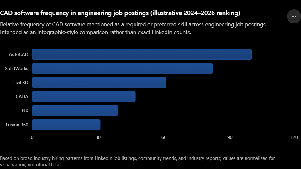
    Bar chart showing CAD software frequency in engineering job postings 2026 with AutoCAD SolidWorks Fusion 360 CATIA NX and Civil 3D ranked by employer demand
    CAD SoftwareJob Posting FrequencyIndustries With Highest DemandTypical Salary Premium vs No CAD SkillCertification Available?
    AutoCADHighest, appears in more engineering job postings than any other single toolAll engineering disciplines, architecture, construction, civil+10 to 20% for verified proficiency; Autodesk Certified Professional (ACP) valuedYes, Autodesk Certified User (ACU) and Professional (ACP)
    SolidWorksVery high, most common 3D CAD requirement in mechanical engineeringMechanical, product design, manufacturing, medical devices+15 to 25% for CSWP/CSWE certification holders vs uncertifiedYes, SOLIDWORKS Certified Professional (CSWP) and Expert (CSWE), highly valued
    Fusion 360Growing rapidly, most common in startups and manufacturing SMEsProduct design startups, CNC manufacturing, consumer products+10 to 15%; Autodesk Certified User level availableYes, Autodesk Certified User in Fusion 360
    CATIAModerate overall; very high in aerospace/automotive specificallyAerospace, automotive OEM, defence, premium consumer products+20 to 35% in specialist aerospace/automotive roles; scarcity premiumYes, Dassault Systemes certified associate and professional levels
    Siemens NXModerate overall; very high in automotive/precision manufacturingAutomotive OEM, Tier 1 suppliers, precision manufacturing, defence+20 to 35% in specialist roles; high scarcity premiumYes, Siemens NX Certified Associate and Professional levels
    AutoCAD Civil 3DHigh in civil/infrastructure sectorCivil engineering, transportation, land development, water infrastructure+15 to 20% vs AutoCAD-only in civil sectorYes, Autodesk Certified Professional in Civil 3D
    OnshapeGrowing; common in hardware startups and mechatronicsHardware startups, mechatronics, IoT device design+10 to 15%; emerging tool with growing employer baseYes, PTC Onshape certification available
    FreeCADLow in commercial job postings (open-source, less employer-required)Academia, open-source hardware, personal projectsMinimal employer premium; primarily valuable for self-developmentNo formal certification
    Career Strategy Insight:  The highest-value CAD investment for most mechanical engineers is SolidWorks proficiency plus CSWP certification. CSWP is employer-recognised, independently validated, and consistently associated with a salary premium of 15 to 25 percent over uncertified peers. For civil and multi-discipline engineers, AutoCAD ACP certification provides the broadest career coverage. For aerospace and automotive-targeting engineers, CATIA or NX proficiency (gained through employer training) is the primary differentiator.

    Frequently Asked Questions (FAQ)

    What is the best CAD software for mechanical engineers?

    For most mechanical engineers, SolidWorks is the best CAD software: it is the most widely used parametric 3D CAD tool in the global mid-market mechanical engineering sector, required in over 65% of mechanical engineering 3D CAD job postings, and has the deepest ecosystem of simulation, sheet metal, and manufacturing tools. For smaller teams and budget-conscious engineers, Autodesk Fusion 360 provides excellent integrated CAD+CAM capability. For aerospace and automotive OEM roles, CATIA or Siemens NX are the industry-mandated standards.

    What CAD software do most engineers use?

    The most widely used CAD software across all engineering disciplines is AutoCAD for 2D drafting and documentation (used in architecture, civil, structural, electrical, mechanical, and MEP engineering). For 3D parametric mechanical design, SolidWorks is the most common tool in the mid-market. For aerospace, CATIA and Siemens NX are the standards. For startups and small teams, Fusion 360 is increasingly common. The tool that appears in the most engineering job postings globally remains AutoCAD by a significant margin.

    Is AutoCAD or SolidWorks better for engineers?

    They serve fundamentally different purposes, so the comparison depends on the engineering role. AutoCAD is best for 2D technical drawing, documentation, and multi-discipline drafting across architecture, civil, structural, and electrical engineering. SolidWorks is best for 3D parametric mechanical design, assembly modelling, simulation, and product development. Many mechanical engineers use both: SolidWorks for 3D design work and AutoCAD for 2D drawing production and documentation.

    What is the best free CAD software for engineers?

    The best free CAD software for engineers depends on use case. Fusion 360 offers the best free professional capability for qualifying personal/startup users (free for non-commercial use and for startups below $100k revenue). FreeCAD is the best fully open-source parametric 3D CAD with no usage restrictions. Onshape (free public plan) provides cloud-native collaboration at zero cost. For 2D drafting, AutoCAD Web has a limited free tier and LibreCAD is fully free and open-source.

    Is Fusion 360 good for professional engineering?

    Yes, Fusion 360 is a professional-grade engineering tool for many applications. It is particularly strong for product design startups, CNC manufacturing engineering, consumer products, and any workflow benefiting from integrated CAD+CAM capability. Its limitations are in large assembly handling (above ~1,000 components), industry acceptance in aerospace and automotive OEM environments (where CATIA and NX are mandated), and drawing documentation maturity compared to SolidWorks or AutoCAD. For the price point ($545/year commercial or free for qualifying use), it offers exceptional value.

    What CAD software is used in aerospace engineering?

    Aerospace engineering primarily uses CATIA (Dassault Systemes) and Siemens NX. Airbus, Dassault Aviation, many European aerospace OEMs, and major defence contractors standardise on CATIA. Boeing, General Motors, Lockheed Martin, and their supply chains typically use NX. CATIA is valued for Class A surface modelling, large digital mockup, and knowledge-based engineering. NX is valued for its integrated CAD/CAM/CAE capability and Teamcenter PLM integration. Both have steep learning curves and are priced for enterprise deployment.

    How long does it take to learn CAD software?

    Learning time varies by tool and target proficiency level. For AutoCAD, productive 2D proficiency typically takes 4 to 8 weeks of regular practice. For SolidWorks, productive 3D modelling competence typically takes 3 to 5 months. For Fusion 360, 2 to 4 months for CAD proficiency, longer to master the CAM workflows. For enterprise tools like CATIA or NX, initial productivity typically takes 6 to 12 months of dedicated training and practice. All tools offer much shorter learning curves if you already have proficiency in a similar competing tool.

    Which CAD software certification is most valuable for engineering careers?

    The most career-valuable CAD certifications for engineers are: SOLIDWORKS Certified Professional (CSWP) for mechanical engineers, consistently associated with 15 to 25% salary premiums; Autodesk Certified Professional (ACP) in AutoCAD for the broadest multi-discipline engineering recognition; and Autodesk Certified Professional in Civil 3D for civil and infrastructure engineering roles. CATIA and NX certifications are valuable but are typically obtained through employer training programs rather than independent self-study.

    Conclusion: How to Make the Final Decision

    The best CAD software for engineers is always context-dependent, and any guide that names a single universal winner is oversimplifying a genuinely complex decision. The frameworks in this guide are designed to cut through that complexity.

    Start with your industry and target employers. If they use SolidWorks, learn SolidWorks. If they use CATIA, that is what matters. If you are a civil engineer, AutoCAD Civil 3D is not optional, it is the baseline. The most common mistake engineers make is choosing a tool based on marketing, price, or personal preference rather than industry and employer alignment.

    Once you have identified the right tool for your industry, the second most important decision is certification. A validated, externally recognised certification (CSWP for SolidWorks, ACP for AutoCAD, Professional for Civil 3D) adds salary premium, recruitment signal, and professional credibility that self-reported proficiency does not.

    For students and early-career engineers: use your free education access to develop genuine proficiency in the tool your industry uses. For established professionals: the investment in one additional CAD certification in a high-demand area (CSWP if you have not done it, Civil 3D ACP if you are in infrastructure) has one of the fastest returns of any professional development investment available.


    Further reading recommendation: Monograph Best Engineering Design Software

    Explore the broader CAD landscape: read CAD Software Explained: Types, Uses, and Best Tools for the complete overview, or deep-dive into AutoCAD Tutorials for Beginners and Professionals to start building the most universally applicable CAD skill in engineering.
  • CAD Software Explained: Types, Uses, and Best Tools 2026

    CAD Software Explained: Types, Uses, and Best Tools 2026

    Computer-Aided Design (CAD) software is one of the most transformative technologies in the history of engineering, architecture, and manufacturing. In four decades it has replaced every drawing board, eliminated most of the calculation errors that cost lives in engineered structures, compressed product development timelines from years to months, and made it possible to design objects of extraordinary geometric complexity with precise dimensional control.

    And yet, for all its ubiquity, CAD software is profoundly misunderstood , even by many of the engineers, architects, and designers who use it daily. Most people know the name of the tool they use. Far fewer understand the category that tool belongs to, why that category exists, how it relates to other CAD categories, or what the technology actually does under the surface to enable the work it supports.

    This pillar guide closes that gap. It explains CAD software from first principles: what it is, where it came from, how it is categorised into distinct types, what each type does and why it was invented, how the major tools within each type compare, how CAD fits into the broader product development and construction workflow, what file formats it uses and why they matter, how the technology is changing with AI and cloud computing, and what career paths are built on it. It is the most comprehensive, readable, and practically useful guide to CAD software available outside of a university textbook.

    Quick Definition:ย  CAD software (Computer-Aided Design software) is any software application used to create, modify, analyse, and document designs with a precision and efficiency that manual drawing cannot match. It ranges from 2D drafting programs that produce technical drawings to parametric 3D solid modelling tools, architectural BIM platforms, aerodynamic simulation environments, and AI-assisted generative design systems.

    What Is CAD Software? A Complete Definition

    CAD software is a category of computer application that enables engineers, architects, designers, and technicians to create precise digital representations of physical objects, structures, and systems. The word “design” in Computer-Aided Design encompasses both the creative act of conceiving a new object and the analytical act of verifying that it will perform as required , making CAD simultaneously a creative and an engineering tool.

    At the most fundamental level, a CAD software application provides a digital environment in which geometric objects (lines, curves, surfaces, solids) can be created, positioned, dimensioned, and modified with precision measured to fractions of a millimetre or micron. Unlike a general-purpose drawing application (such as Adobe Illustrator or Microsoft PowerPoint), CAD software models geometry in actual physical coordinates , every object has a precise location, dimension, and relationship to every other object, defined in the same units of measurement (millimetres, inches, metres) that the physical object will eventually be produced in.

    What Makes CAD Different from General Drawing Software

    FeatureCAD SoftwareGeneral Drawing / Illustration Software
    Coordinate precisionExact geometric coordinates , objects are positioned to engineering precisionApproximate pixel or point positions , not dimensionally accurate
    UnitsReal-world measurement units (mm, in, m) throughoutArbitrary canvas units , not calibrated to physical dimensions
    Object relationshipsGeometric constraints and parametric relationships between objectsObjects are independent , no geometric relationships
    Dimensional accuracyDimensions are exact and queryable , DIST, AREA, MASS PROPERTIES commandsDimensions are approximations , not guaranteed accurate
    Manufacturing outputProduces drawings and data directly usable for manufacturing, fabrication, and constructionProduces artwork for visual communication, not manufacturing
    File formatsEngineering formats: DWG, DXF, STEP, IGES, STL, IFCGraphic formats: AI, PDF, SVG, PSD, PNG

    The Three Core Uses of CAD Software

    All CAD software serves three fundamental purposes, which together define what computer-aided design means in practice:

    • Design and modelling: Creating the geometric representation of a product, structure, or system , the digital model from which everything else flows.
    • Analysis and verification: Confirming that the design meets its requirements , structurally sound, thermally stable, manufacturable, collision-free , before anything physical is built.
    • Documentation and communication: Producing the drawings, specifications, bills of materials, and data files that communicate the design to manufacturers, fabricators, constructors, and clients.
    Scale of Impact:ย  According to Grand View Research, the global CAD software market was valued at $12.0 billion in 2024 and is projected to reach $17.5 billion by 2030, growing at a CAGR of 6.5%. Architectural CAD software alone is projected to reach $30.17 billion by 2026, driven by cloud-based BIM adoption, AI-assisted design, and global construction digitisation. CAD is no longer a specialist engineering tool , it is infrastructure for the entire built environment, product manufacturing, and energy systems industries.

    The History of CAD Software: From Drawing Boards to AI

    The history of CAD software is one of the most important stories in the history of technology. It is the story of how an entire profession was transformed from pencil-and-paper craft into digital engineering in less than 50 years.

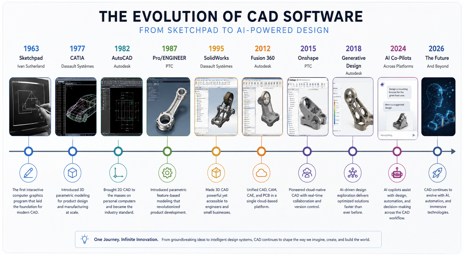
    CAD software history timeline from 1963 Sketchpad to 2026 AI-assisted design showing AutoCAD SolidWorks CATIA Fusion 360 and cloud CAD milestones

    1960s: The Birth of Computer-Aided Design

    The concept of computer-aided design was born in 1963 when Ivan Sutherland, a PhD student at MIT, presented Sketchpad , the first interactive computer graphics system , in his doctoral thesis. Sketchpad allowed users to draw geometric shapes on a CRT display using a light pen and introduced fundamental CAD concepts including constraints, object hierarchies, and parametric editing that are still central to modern CAD software 60 years later.

    Sutherland’s work inspired automotive and aerospace companies to explore computer graphics for engineering design. General Motors partnered with IBM to develop DAC-1 (Design Augmented by Computer) for automobile body design in 1963. Lockheed Aviation developed CADAM (Computer Augmented Design and Manufacturing) in the late 1960s. These early systems ran on room-sized mainframe computers and cost millions of dollars , accessible only to the largest industrial corporations.

    1970s: Proprietary Workstation CAD

    The 1970s brought the first commercial CAD systems. CATIA was developed by Dassault Systemes (originally for Dassault Aviation) beginning in 1977. CADAM was acquired by Lockheed and commercialised. Unigraphics (the predecessor to Siemens NX) and Pro/ENGINEER (the predecessor to PTC Creo) were both developed in this decade. These systems ran on dedicated engineering workstations costing $50,000 to $150,000 per seat , still expensive, but beginning to be accessible to mid-sized engineering firms.

    The critical innovation of this era was the introduction of 3D wireframe and surface modelling: the ability to represent the full three-dimensional form of an object in the computer rather than just its 2D projections. This transformed CAD from an expensive drafting tool into a genuine design tool, enabling engineers to visualise, analyse, and refine 3D geometry before physical prototypes were built.

    1982: AutoCAD and the Personal Computer Revolution

    The most consequential event in the history of CAD software was the release of AutoCAD by Autodesk on 1 December 1982 at COMDEX in Las Vegas. AutoCAD was the first fully functional CAD program to run on a personal computer. At an initial price of $1,000 (compared to $50,000+ for competing workstation CAD systems), it democratised CAD access and within a decade had become the global standard for technical drawing, destroying the commercial drawing board market entirely.

    AutoCAD’s introduction did more than make CAD affordable. It established the DWG file format as the universal language of engineering drawings, created the concept of a command-line interface for precision CAD input, and set the user interaction paradigm that most 2D CAD tools still follow today.

    1987-1995: The Parametric Revolution

    The next transformational shift came with the introduction of parametric feature-based 3D solid modelling. PTC released Pro/ENGINEER in 1987, the first commercially successful fully parametric 3D CAD system. Pro/ENGINEER’s fundamental innovation was that every feature in a 3D model was defined not just by its geometry but by its parameters (dimensions, constraints, relationships to other features) and its creation intent (this boss is on the top face of this body, at this offset from this edge).

    This meant that changing a parameter automatically updated the entire model: change the hole diameter and every related feature updated accordingly. The parametric approach was a profound shift from direct geometry manipulation , it encoded the engineer’s design intent into the model rather than just its current geometry. SolidWorks launched in 1995 with a Windows-native interface and significantly lower cost, bringing parametric 3D CAD to the mainstream mechanical engineering market.

    2000s: Integration, Simulation, and PLM

    The 2000s brought the integration of CAD with simulation (CAE), manufacturing programming (CAM), and product lifecycle management (PLM). ANSYS, MSC Nastran, and SolidWorks Simulation brought finite element analysis to the design engineer’s desktop. Mastercam, Fusion 360 (CAM), and NX CAM integrated manufacturing programming with the design model. Dassault’s 3DEXPERIENCE platform and Siemens’ Teamcenter provided the PLM backbone to manage complex multi-disciplinary product data across engineering organisations.

    2010s-Present: Cloud, Collaboration, AI, and Generative Design

    The defining developments of the current era are the shift to cloud-native CAD (Onshape launched 2015, Fusion 360 hybrid cloud launched 2013), the integration of AI and generative design (Autodesk introduced generative design in Fusion 360 in 2018), and the rapid growth of BIM (Building Information Modelling) as the standard for construction project design and coordination. In 2024-2026, conversational AI interfaces (CAD assistants, natural language design query tools, AI-powered topology optimisation) are beginning to reshape the daily workflow of CAD practitioners for the first time since the introduction of parametric modelling.

    How CAD Software Works: The Core Technology Concepts

    Understanding what happens inside a CAD software application when you draw a line, extrude a profile, or run a simulation makes the entire landscape of CAD types and tools more logical. Most of the distinctions between CAD tools trace back to fundamental differences in the underlying technology.

    Geometric Kernels: The Mathematical Engine

    Every 3D CAD tool is built on a geometric kernel , a mathematical library that handles the representation and manipulation of 3D geometry. The two dominant commercial geometric kernels are Parasolid (owned by Siemens) and ACIS (owned by Spatial Corporation / Dassault). SolidWorks, NX, Solid Edge, and many others use Parasolid. AutoCAD 3D solid modelling, Inventor, and some others use ACIS. CATIA uses its own proprietary kernel.

    The geometric kernel determines what types of geometry the CAD tool can represent, how accurately it handles complex operations like Boolean intersections and filleting, and what output formats it can produce. This is why files exported from one CAD tool often need to be translated through a neutral format (STEP, IGES) when moving to a different tool , the underlying geometry representations are different.

    Feature Trees and Parametric History

    Parametric 3D CAD tools maintain a feature tree (also called a model tree or design tree) , a chronological record of every operation performed to create the 3D model. The feature tree is the model’s construction history: it records that the base extrusion came first, then a fillet was applied, then a hole was added, then a pattern of holes was created.

    The feature tree is what makes parametric CAD models editable by intent rather than by geometry. Changing the diameter of the original hole also updates the pattern of holes, because the pattern references the parent hole’s geometry. Parametric models can be updated by editing parameters anywhere in the feature tree, and the model rebuilds from that point downward.

    Constraint Solving

    2D CAD sketches and 3D assembly positions are governed by constraint solvers , mathematical engines that enforce geometric relationships between objects. A coincident constraint forces two points to occupy the same location. A tangent constraint forces a line to be tangent to a circle. A perpendicular constraint forces two lines to meet at 90 degrees. When constraints are fully satisfied, the sketch or assembly is fully constrained: it cannot move or deform except by changing the parameters or constraints themselves. Constraint solving is the foundation of parametric design intent.

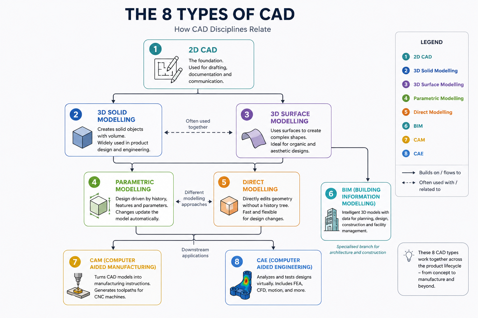
    The 8 Types of CAD Software Explained

    CAD software is not a single technology. It is a family of distinct types, each developed to address a specific design, analysis, or documentation problem. Understanding the eight primary types of CAD software is the conceptual foundation for understanding the entire CAD landscape.

    Diagram showing the 8 types of CAD software and their relationships including 2D CAD, 3D solid modelling, parametric, direct modelling, surface modelling, BIM, CAM, and CAE simulation
    TypePrimary PurposeOutput ProducedKey TechnologiesRepresentative Tools
    2D CADTechnical drawing and documentationEngineering drawings, construction plans, schematicsVector geometry, layers, annotation, plottingAutoCAD, AutoCAD LT, LibreCAD, QCAD
    3D Solid ModellingCreating 3D volumetric models for design and manufacturing3D solid models, assembly models, rendered visualisationsB-rep solid geometry, feature trees, Boolean operationsSolidWorks, Inventor, Solid Edge
    Parametric CADIntelligent design with parametric relationships and constraintsParametric models that update intelligently when changedFeature history, constraint solving, parametric equationsSolidWorks, CATIA, NX, Creo, Fusion 360
    Direct ModellingFast, flexible geometry manipulation without history constraints3D models editable without feature history dependenciesDirect geometry manipulation, face pushing/pullingSpaceClaim, Fusion 360 (direct mode), Creo (Flexible Modelling)
    Surface ModellingComplex curved surface design for aesthetics and aerodynamicsClass A surfaces, organic shapes, complex curvature-controlled formsNURBS surfaces, continuity analysis, curvature-based toolsCATIA FreeStyle, NX Freeform, Rhino, Alias
    BIM (Building Information Modelling)Integrated building design with intelligent building elementsMulti-discipline building models with embedded dataObject-based parametric building components, IFCRevit, ArchiCAD, Vectorworks, Allplan
    CAD/CAMConnecting design models to manufacturing machine programmingCNC toolpaths, machining simulations, G-codeToolpath algorithms, machine kinematics, material databasesFusion 360 (CAM), Mastercam, NX CAM, Siemens NX
    CAD/CAE (Simulation)Analysing design performance under simulated conditionsStress results, thermal distributions, fluid flow results, factor of safetyFEA solvers (Nastran, Calculix), CFD solvers (Fluent, OpenFOAM)ANSYS, SolidWorks Simulation, COMSOL, Abaqus

    Type 1: 2D CAD Software , Technical Drafting and Documentation

    2D CAD software produces flat technical drawings: engineering drawings, architectural plans, structural layouts, electrical schematics, and construction documents. It is the direct digital successor to the manual drawing board and remains the primary output format for technical communication between engineers, architects, and construction and manufacturing trades.

    Despite the growth of 3D CAD and BIM, 2D CAD drawings remain the primary legally binding deliverable in most engineering, construction, and manufacturing contracts globally. Fabricators, contractors, and manufacturers work from 2D drawings. Building permits are issued on the basis of 2D plans. Quality inspection is conducted against 2D engineering drawings. The 3D model is increasingly the design tool; the 2D drawing remains the communication and contract instrument.

    What 2D CAD Produces

    • Engineering drawings: Component drawings with dimensions, tolerances, surface finish, and GD&T callouts for manufacturing
    • Assembly drawings: Multi-part drawings showing how components fit together with part references and bill of materials
    • Architectural plans: Floor plans, sections, elevations, and construction details for building projects
    • Electrical schematics: Circuit diagrams, wiring diagrams, and panel layouts for electrical systems
    • Civil engineering plans: Site plans, road layouts, drainage networks, and utility routing drawings
    • P&ID diagrams: Piping and instrumentation diagrams for chemical processes and industrial plants

    The undisputed leader in 2D CAD is AutoCAD, with over 4 million active subscribers globally and a market share in 2D engineering drawing that no competitor comes close to matching. Its DWG file format is the universal standard for 2D technical drawing exchange. AutoCAD LT ($570/year) provides the full 2D drafting capability without 3D modelling for users who only need documentation.

    Type 2: 3D Solid Modelling CAD

    3D solid modelling is the representation of physical objects as mathematically defined volumetric solids in a three-dimensional coordinate space. A solid model has mass, volume, surface area, and centre of mass , it is a complete digital representation of a physical object that can be interrogated, modified, and used to generate manufacturing instructions.

    Solid models use boundary representation (B-rep) , the solid is defined by its bounding surfaces (faces, edges, and vertices) and the mathematical relationships between them. The Parasolid and ACIS geometric kernels use B-rep to represent solids, as does every major commercial 3D CAD tool.

    What 3D Solid Modelling Enables

    • Interference checking: Automatically detecting whether two components in an assembly physically overlap (clash) , critical for verifying assembly feasibility before manufacturing
    • Mass properties: Calculating weight, centre of gravity, moments of inertia , essential for structural analysis and balance calculations
    • Automated drawing generation: Creating 2D orthographic views, sections, and details automatically from the 3D model , far faster than drawing views manually
    • Visualisation and rendering: Producing photorealistic images of the product before any physical prototype exists
    • Simulation input: Providing the geometry for FEA stress analysis, CFD fluid simulation, and thermal analysis
    • Manufacturing instructions: Generating toolpaths for CNC machining directly from the solid model geometry

    Type 3: Parametric CAD Software

    Parametric CAD is not a separate type of CAD so much as a design methodology , the most important methodology in modern engineering CAD. A parametric CAD model encodes the design intent as well as the geometry: relationships between features, governing dimensions, and the logical order in which features are created are all part of the model definition.

    The defining characteristic of parametric CAD is that changing a parameter value automatically propagates through the entire model, updating all dependent features according to the design intent encoded when the model was built. A parametric model of a bolt pattern does not just record where the holes are , it records that the holes are equally spaced around a bolt circle of a specified diameter, so changing the bolt circle diameter automatically repositions all holes correctly.

    Parametric vs Non-Parametric CAD

    AspectParametric CADNon-Parametric (Direct) CAD
    Change propagationChanges to parameters automatically update entire modelChanges apply only to the selected geometry; no automatic propagation
    Design intent storageDesign intent encoded in feature tree and constraintsGeometry only , no stored design intent
    Edit flexibilityStructured: edits must respect feature dependenciesFlexible: any face or edge can be moved freely
    Best forProduction design, repeated design iterations, family-of-parts designConcept modelling, imported geometry repair, quick shape exploration
    Learning curveSteeper: must plan feature structure to edit reliablyFaster to start: no upfront structural planning required
    Major toolsSolidWorks, CATIA, NX, Creo, InventorSpaceClaim, Fusion 360 (direct), Creo Flexible Modelling Extension

    Type 4: Direct Modelling (Explicit) CAD

    Direct modelling (also called explicit modelling or history-free modelling) is an approach where the engineer manipulates geometry directly , pushing faces, pulling edges, blending surfaces , without a parametric feature history constraining those manipulations. Each edit acts on the current state of the geometry rather than on a record of how it was built.

    Direct modelling has two primary use cases: fast concept exploration (where the freedom to modify without feature history constraints accelerates early-stage design) and working with imported geometry (where files from other CAD systems arrive as dumb solids without feature history). Tools like Ansys SpaceClaim (now SpaceClaim Engineer) are specifically optimised for the latter , preparing imported CAD geometry for FEA simulation by simplifying, repairing, and modifying solids that have no parametric history.

    Type 5: Surface Modelling CAD

    Surface modelling creates 3D shapes as collections of mathematical surfaces rather than as volumetric solids. Where solid modelling is analogous to sculpting a clay block, surface modelling is analogous to bending and joining sheets of material , building the outer skin of an object face by face.

    Surface modelling is essential for any design where the precise shape and curvature of the exterior surface is itself the primary design criterion: automotive body panels (where surface curvature affects aerodynamics, water runoff, and visual reflection quality), aircraft fuselage and wing skins (where aerodynamic performance is surface-quality dependent), and premium consumer product casings (where the visual and tactile quality of the surface is a primary differentiator).

    NURBS: The Mathematics of CAD Surfaces

    Most CAD surface modelling is based on NURBS (Non-Uniform Rational B-Splines) , a mathematical representation that can define smooth curves and surfaces of arbitrary complexity with a compact set of control points and weights. NURBS surfaces can represent everything from a perfect cylinder to a complex organic aerodynamic shape, and they export to neutral formats (IGES, STEP) without losing surface quality.

    Class A Surfaces

    The highest standard of surface quality in automotive and consumer product design is called Class A surfaces: surfaces that are not just smooth but have mathematically perfect curvature continuity across all joins. Class A is the standard for automotive exterior body panels and is tested by analysing how light and environment reflections behave across the surface , any discontinuity in curvature shows up as a visible distortion in the reflection. CATIA FreeStyle and Autodesk Alias are the primary tools for Class A surface creation.

    Type 6: Building Information Modelling (BIM) Software

    BIM software represents the application of CAD technology to the architecture, engineering, and construction (AEC) industry, with a fundamental difference from conventional CAD: in BIM, the model is not just a collection of geometric shapes but a database of intelligent building objects , walls, doors, windows, beams, pipes, ducts , each containing geometric, physical, and functional data about the real building element it represents.

    A BIM model of a building knows that the object labelled ‘Wall Type A’ is a 200mm thick load-bearing concrete wall with specific thermal properties, fire rating, and finish specifications. When a door is placed in that wall, the BIM software automatically creates the opening in the wall geometry, adjusts the wall area calculations, and records that the wall has a door of a specific type. This intelligence enables automatic generation of schedules, quantity takeoffs, energy analyses, and clash detection reports from a single coordinated model.

    BIM Levels of Development

    BIM LevelWhat It MeansKey Capability Enabled
    LOD 100 (Conceptual)Approximate size, shape, location, and orientationSite planning, massing studies, conceptual energy analysis
    LOD 200 (Schematic)Approximate geometry with generic object types, quantities, and systemsPreliminary clash detection, approximate cost estimating, coordination between disciplines
    LOD 300 (Design Development)Specific geometry, size, shape, location, orientation with real object typesDetailed clash detection, accurate quantity takeoff, construction coordination, permit drawings
    LOD 350 (Construction)Full construction detail with interface information for adjacent elementsComplete construction coordination, fabrication drawings, MEP coordination
    LOD 400 (Fabrication)Full fabrication and assembly detail , as-built representationOff-site fabrication, assembly sequencing, shop drawings
    LOD 500 (As-Built)Model verified on-site to actual conditionsFacilities management, maintenance planning, digital twin

    The dominant BIM software tool globally is Autodesk Revit, which holds approximately 60 to 70 percent of the BIM market for architectural and structural design. Graphisoft ArchiCAD is a strong competitor, particularly in Europe. Bentley’s OpenBuildings Designer is used for large infrastructure projects. The open exchange format for BIM data is IFC (Industry Foundation Classes), developed by buildingSMART International, which allows different BIM tools to exchange building model data without proprietary format dependency.

    Type 7: CAD/CAM Software , Design to Manufacture

    CAD/CAM software (Computer-Aided Design / Computer-Aided Manufacturing) combines 3D design tools with manufacturing programming tools in a single integrated workflow. The “manufacturing” part (CAM) generates the machine instructions , typically CNC toolpaths and G-code , needed to produce the designed component on a CNC milling machine, lathe, router, plasma cutter, or other computer-controlled manufacturing equipment.

    The fundamental advantage of an integrated CAD/CAM workflow is that the same geometric model used for design is used directly for manufacturing programming , there is no need to recreate or import geometry into a separate CAM package. Any change to the design model automatically updates the associated toolpaths when the CAM program is regenerated, reducing the risk of manufacturing from outdated geometry.

    What CAM Software Does

    • Toolpath generation: Calculates the precise path the cutting tool must follow to remove material from a workpiece and produce the designed geometry
    • Machine simulation: Simulates the complete cutting process to verify toolpaths, check for collisions between the tool/holder and workpiece/fixture, and estimate machining time
    • G-code output: Generates the machine-specific numerical control code (G-code) that is loaded into the CNC machine controller
    • Setup documentation: Produces setup sheets describing workholding, tool selection, cutting parameters, and operation sequence for the machinist

    The most significant CAD/CAM development for everyday engineers in recent years is Autodesk Fusion 360’s integrated CAD+CAM workflow. Fusion 360 provides fully capable 2.5-axis, 3-axis, 4-axis, and 5-axis milling, turning, and wire EDM programming alongside its 3D design tools in a single subscription at a price accessible to small manufacturers and individual engineers.

    Type 8: CAD/CAE Software , Simulation and Analysis

    CAD/CAE software (Computer-Aided Engineering) uses the geometry of a CAD model as the input for numerical simulation , predicting how a design will perform under real-world conditions before any physical prototype is built. The economic and safety value of this capability is enormous: finding that a bracket will fail under load in a simulation takes minutes and costs nothing to fix; finding it in a physical test takes weeks and may require costly tooling changes; finding it in service may cost lives.

    The Primary Types of CAE Simulation

    • Finite Element Analysis (FEA): Predicts structural stress, strain, deflection, and failure in solid components under mechanical, thermal, or dynamic loading. The most widely used simulation type in mechanical engineering.
    • Computational Fluid Dynamics (CFD): Simulates fluid flow (liquid or gas) around or through a 3D geometry , predicting aerodynamic drag, lift, pressure drops, heat transfer, and flow distributions.
    • Thermal analysis: Predicts temperature distributions through conduction, convection, and radiation , critical for electronics cooling, engine thermal management, and HVAC system design.
    • Modal analysis / dynamics: Predicts natural frequencies and vibration mode shapes of structures , essential for avoiding resonance failures.
    • Multi-physics simulation: Couples multiple physics domains (structural + thermal + fluid) in a single simulation , used for complex coupled problems like thermal expansion causing structural stress.

    The dominant CAE platform globally is ANSYS, which provides FEA, CFD, thermal, electromagnetic, and multi-physics simulation tools. SolidWorks Simulation provides integrated FEA within the SolidWorks environment. COMSOL Multiphysics specialises in coupled multi-physics problems. Autodesk Nastran and MSC Nastran are the aerospace and automotive standard for structural analysis.

    The Three Modelling Paradigms: Solid, Surface, and Mesh

    Within 3D CAD, three distinct mathematical paradigms are used to represent geometry. Understanding them explains why different CAD tools are used for different types of design work.

    ParadigmHow Geometry Is RepresentedBest ForStrengthsLimitations
    Solid Modelling (B-rep)Closed volumetric solids defined by bounding surfaces, edges, and verticesMechanical engineering, product design, structural components, anything that will be manufacturedMathematically complete, mass properties calculable, Boolean operations, FEA-readyLess suited to organic/sculptural shapes; requires watertight geometry
    Surface Modelling (NURBS)Collections of smooth mathematical surfaces without enclosing a volumeAutomotive styling, aerospace aerodynamics, consumer product aesthetics, complex curved shapesPerfect curvature control, Class A surfaces achievable, handles organic shapes wellSurfaces must be manually stitched and made watertight for manufacturing
    Mesh / Polygon ModellingGeometry approximated by a mesh of flat polygonal faces (triangles or quads)Game assets, visual rendering, 3D printing of organic shapes, reverse engineering from scan dataHandles highly complex organic shapes, fast for visualisation, compatible with 3D printingNot dimensionally precise, limited manufacturing suitability, large file sizes for complex models

    Modern professional CAD tools are increasingly hybrid, supporting multiple modelling paradigms within the same environment. SolidWorks supports both solid and surface modelling. CATIA and NX support all three. Fusion 360 integrates solid, surface, and mesh (T-spline) modelling. The ability to move fluidly between paradigms , starting with surface forms, solidifying them for structural analysis, and exporting mesh for visualisation , is increasingly a defining capability of enterprise-class CAD platforms.

    How CAD Fits into the Product Development Workflow

    CAD software does not exist in isolation. It sits within a structured product development or construction workflow that defines how design intent is captured, developed, verified, documented, and communicated from initial concept through to finished product or built structure. Understanding where each type of CAD fits in this workflow clarifies why different tools are used at different stages.

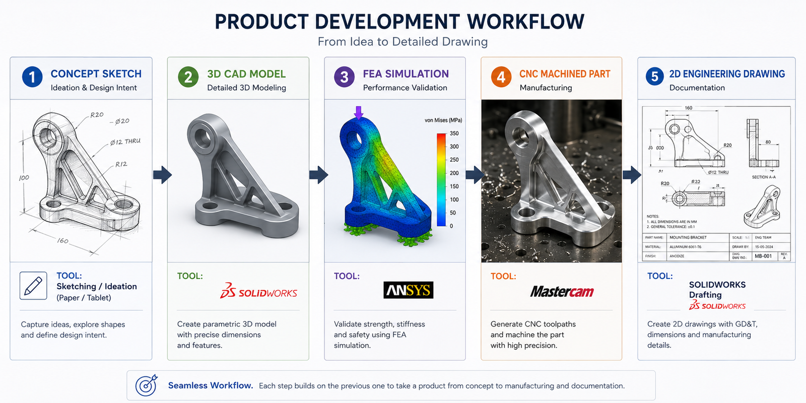
    Product development workflow diagram showing how CAD software types are used at each stage from concept design through 3D modelling FEA simulation and CNC manufacturing to 2D documentation
    Workflow StagePrimary ActivityCAD Type UsedTypical ToolsOutput
    Concept and IdeationSketching, form exploration, initial proportioningDirect modelling, sketch tools, mesh modellingFusion 360, SketchUp, Shapr3D, BlenderConcept sketches, rough 3D form studies
    Schematic DesignEstablishing spatial layout, system routing, design intent2D CAD, BIM, schematic toolsAutoCAD, Revit (BIM), Visio (schematics)Schematic drawings, layout plans, system diagrams
    Detail DesignFully detailed 3D models with all geometry, tolerances, and materialsParametric 3D CAD, surface CAD (for Class A)SolidWorks, CATIA, NX, Creo3D solid models, assembly models
    Analysis and SimulationVerifying structural integrity, fluid performance, thermal behaviourCAE simulation softwareANSYS, SolidWorks Simulation, COMSOL, FluentFEA stress results, CFD flow fields, factor of safety reports
    Manufacturing DocumentationCreating drawings, specifications, BOM, NC programs2D CAD, CAD/CAMAutoCAD, SolidWorks Drawing, Fusion 360 CAMEngineering drawings, bills of materials, CNC toolpaths, G-code
    Fabrication and ConstructionProducing the physical object or structure2D drawings, CAM G-code, BIM modelsFactory equipment, CNC machines, construction sitePhysical product or built structure
    Operations and MaintenanceManaging the built asset throughout its service lifeDigital twin, BIM (facilities), PLMBentley AssetWise, IBM Maximo, Autodesk TandemAs-built models, maintenance records, performance data

    CAD File Formats Explained

    CAD file formats are one of the most practically important topics for working engineers and designers. The choice of file format for exchanging CAD data between tools, teams, and organisations determines what information is preserved, what is lost, and what compatibility problems will arise.

    FormatTypeWhat It PreservesBest Used ForLimitations
    DWGNative (Autodesk)Full 2D drawing content: all AutoCAD objects, layers, styles, blocks, attributesSharing between AutoCAD users; universal 2D drawing exchangeProprietary format with version compatibility issues across AutoCAD versions
    DXFOpen interchange2D geometry, layers, blocks , simplified vs DWGSending 2D drawings to non-AutoCAD tools, CNC machines, laser cuttersComplex AutoCAD objects simplified or lost; older versions lose newer features
    STEP (.stp/.step)Open 3D neutralFull solid geometry, B-rep, assembly structure, some metadataGold standard for 3D solid model exchange between different CAD toolsDoes not preserve parametric history or feature trees
    IGES (.igs/.iges)Open 3D neutral (older)Surfaces, solids (B-rep), some assembly dataLegacy 3D exchange, particularly for surface-heavy aerospace/automotive dataOlder standard; STEP is generally preferred for new work
    STL3D printing / meshTriangle mesh approximation of 3D surface , no solid data3D printing, rapid prototyping, reverse engineering, visualisationNo exact geometry (faceted approximation), no parametric data, no units
    SLDPRT / SLDASMNative (SolidWorks)Full parametric feature history, assembly structure, matesWorking within SolidWorks environment; sharing with other SolidWorks usersOnly readable in SolidWorks (or with SolidWorks viewer)
    IFCOpen BIMFull BIM model: building objects, geometry, metadata, relationships, schedulesExchanging BIM models between Revit, ArchiCAD, and other BIM toolsNot all tools implement IFC equally; some data loss common across platforms
    FBXVisualisation / animationMesh geometry, materials, textures, animation data3D rendering, visualisation, game engine importNot suitable for engineering manufacturing
    Parasolid (.x_t)Geometric kernel neutralFull B-rep solid geometry without feature historyTransferring solid geometry between tools sharing Parasolid kernelLimited tool support compared to STEP
    OBJMesh / visualisationPolygon mesh, materials, texture coordinates3D visualisation, rendering, web 3D, game assetsNo engineering precision, no solid data, no dimensions
    File Format Decision Rule:ย  For 3D solid model exchange between different CAD tools: use STEP (.step). It is the most universally supported neutral 3D format and preserves solid geometry with the least data loss. For 2D drawing exchange with non-AutoCAD users or fabrication services: use DXF (R14). For 3D printing: use STL. For BIM model exchange: use IFC. Always keep your native format (.sldprt, .dwg, .rvt) as the master file.

    Desktop CAD vs Cloud-Native CAD: Architecture and Trade-offs

    The fundamental architecture of CAD software , whether it runs on a local workstation or lives in the cloud , is one of the most consequential decisions in modern CAD adoption. This is not just a technical question. It affects security, collaboration, hardware cost, IT overhead, and the long-term direction of the engineering workflow.

    DimensionDesktop CADCloud-Native CAD
    Data locationLocal hard drive or company serverVendor cloud (AWS, Google, Azure infrastructure)
    ProcessingLocal CPU/GPU , performance limited by workstation specHybrid: geometry solving local, storage and collaboration cloud
    CollaborationPDM/PLM required (Vault, Teamcenter, Windchill)Built-in real-time collaboration without PDM infrastructure
    Version controlManual (naming conventions) or PDM-managedAutomatic, branching/merging model similar to git
    Offline workingFull functionalityReduced , most operations require internet
    Hardware costHigh-spec workstation required ($2,000-$8,000+)Any modern computer with web browser
    IT overheadSignificant , installs, updates, licence servers, PDM adminMinimal , vendor manages infrastructure
    Data security / IPData under company controlData on vendor infrastructure , IP risk consideration
    Large assembly performanceBetter , local processing not network-limitedLimited , large assemblies can be slow over network
    Feature maturityMost mature , decades of developmentImproving rapidly , some gaps vs desktop at extremes
    Best forEnterprise engineering, large assemblies, aerospace, automotive, any IP-sensitive sectorStartups, SMEs, remote teams, hardware companies, rapid product development

    The CAD Software Ecosystem: Point Tools vs Integrated Suites

    The CAD software ecosystem is structured into three distinct categories that reflect different approaches to the relationship between design, simulation, manufacturing, and data management:

    Point Tools

    Point tools are software applications designed to do one thing exceptionally well. AutoCAD is a point tool for 2D drafting. ANSYS Fluent is a point tool for CFD. Mastercam is a point tool for CAM. Point tools offer the deepest capability in their specific domain and are often the preferred choice of specialists, but they require file translation workflows when moving data between stages of the development process.

    Integrated Suites

    Integrated suites combine multiple CAD, simulation, and data management capabilities within a single platform and data model. Siemens NX integrates CAD, CAM, and CAE. Autodesk Fusion 360 integrates CAD, CAM, and simulation. Dassault 3DEXPERIENCE integrates SolidWorks/CATIA, simulation, and PLM. Integrated suites eliminate file translation between stages and ensure that the analysis model is always in sync with the design model, at the cost of less depth in any individual domain compared to the best specialist point tools.

    Platform Ecosystems

    The largest CAD vendors have evolved from selling software tools to building platform ecosystems that connect CAD tools with PDM, PLM, ERP, simulation, generative design, IoT, and digital twin technologies. Autodesk’s Platform Services (formerly Forge) and Construction Cloud, Dassault’s 3DEXPERIENCE Marketplace, Siemens’ Xcelerator portfolio, and PTC’s ThingWorx IoT + Windchill PLM all represent attempts to expand the value of CAD from a design tool into the connective tissue of the entire product lifecycle.

    Best CAD Software by Engineering and Design Discipline

    DisciplinePrimary CAD ToolAlternative / Specialist ToolKey Reason
    Mechanical Engineering (Product Design)SolidWorksAutodesk Inventor or Fusion 360Dominant market share, largest ecosystem, most employer-required parametric 3D tool in mid-market
    Mechanical Engineering (Enterprise/Aerospace)CATIA or Siemens NXPTC CreoMandated by major aerospace and automotive OEMs; only tools with the scale for complex programs
    Civil EngineeringAutoCAD Civil 3DBentley MicroStation / OpenRoadsDominant for road, drainage, and site design; Bentley for large infrastructure networks
    Architecture (Documentation)AutoCADMicroDraft, VectorWorksUniversal standard for architectural technical drawings and construction documentation
    Architecture (BIM)Autodesk RevitGraphisoft ArchiCADMarket-leading BIM platform for architectural design and multi-discipline coordination
    Structural EngineeringAutoCADTekla Structures (structural steel)AutoCAD for detailing; Tekla for 3D structural steel fabrication modelling
    Electrical EngineeringAutoCAD ElectricalEPLAN (EDA, not traditional CAD)AutoCAD Electrical toolset for wiring diagrams; EPLAN for complex panel design
    Manufacturing / CNCFusion 360 (CAD+CAM)Mastercam, NX CAMFusion 360’s integrated CAD+CAM at competitive price; Mastercam for advanced multi-axis
    Product Design / Industrial DesignFusion 360 or Rhino 3DSolidWorks, Alias (styling)Fusion 360 for functional design; Rhino for complex form; Alias for automotive Class A styling
    3D Printing / AdditiveFusion 360 or nTopSolidWorks, FreeCADFusion 360 has best generative/lattice design for AM; nTop (nTopology) for advanced lattice structures

    AI and the Future of CAD Software

    Artificial intelligence is beginning to transform CAD software at a pace that is accelerating in 2024 and 2026. The changes range from incremental productivity improvements to potentially fundamental shifts in how engineering design is done.

    Generative Design

    Generative design uses AI optimisation algorithms to explore thousands of design configurations based on engineering constraints defined by the engineer: load cases, material constraints, manufacturing method, mass targets, and performance objectives. The resulting geometries are often organic in form , mathematically optimised rather than intuitively designed , and frequently achieve the same structural performance as conventional designs at 20 to 50 percent lower mass.

    Autodesk’s generative design tools (in Fusion 360 and Inventor) are the most widely deployed. nTop (nTopology) specialises in lattice and field-driven generative structures for additive manufacturing. SOLIDWORKS AI Topology Study provides topology optimisation within the SolidWorks environment.

    AI-Assisted Design Workflows

    • SOLIDWORKS Aura (2026): An AI co-pilot embedded in SolidWorks that answers design questions, suggests features, and assists with model creation through conversational interaction.
    • Autodesk AI (Fusion 360 / AutoCAD): AI-powered command autocomplete, design suggestions, and automated drawing creation features being rolled out across Autodesk products.
    • Physics-Informed Neural Networks (PINNs): Research-stage AI that can solve FEA and CFD problems at speeds orders of magnitude faster than traditional solvers, enabling real-time simulation during design.
    • Automated drawing creation: AI tools that automatically generate 2D drawing views, add dimensions, and create title blocks from 3D models, reducing documentation time significantly.

    The Long-Term Trajectory

    The convergence of AI, generative design, and digital twin technology is moving CAD software toward a future where the engineer’s role shifts from geometry creation toward design intent specification: defining the problem (loads, materials, constraints, cost targets) and evaluating the AI-generated solutions rather than manually creating every geometric feature. This is not imminent for most engineering work , the complexity and safety criticality of most engineered products ensures that human engineering judgement will remain central for decades. But the direction of travel is clear and the pace is accelerating.

    CAD Software Career Paths and Certifications

    Proficiency in CAD software is not a career in itself , it is a foundational skill that amplifies the value of engineering, architecture, and design expertise. The career paths built on CAD proficiency span roles from CAD technician through to engineering director, and the salary premium for certified CAD proficiency is consistently documented across all major engineering job markets.

    Career PathPrimary CAD ToolsKey CertificationsTypical Entry Salary (US)Senior Potential
    Mechanical Design EngineerSolidWorks or NX/CATIACSWP, CSWE (SolidWorks)$65,000-$80,000$110,000-$150,000+
    Civil/Infrastructure EngineerAutoCAD Civil 3D, MicroStationAutodesk ACP Civil 3D$60,000-$75,000$95,000-$130,000
    Structural EngineerAutoCAD, Tekla, RevitAutodesk ACP, Tekla certification$60,000-$72,000$90,000-$125,000
    Architectural DesignerAutoCAD, RevitAutodesk ACP AutoCAD/Revit$55,000-$70,000$85,000-$120,000
    Manufacturing/CNC EngineerFusion 360, Mastercam, NXAutodesk CAM certification$60,000-$75,000$90,000-$120,000
    CAE/Simulation EngineerANSYS, SolidWorks Simulation, AbaqusANSYS certification programmes$70,000-$90,000$115,000-$155,000
    BIM Manager / CoordinatorRevit, Navisworks, Civil 3DAutodesk Certified Professional (Revit)$65,000-$80,000$95,000-$130,000
    Aerospace Structural EngineerCATIA, NX, ANSYS NastranCATIA/NX certificates, PE licence$80,000-$100,000$130,000-$180,000+
    Certification Strategy:ย  The highest-return CAD certification investment for most engineers in 2026 is the SOLIDWORKS Certified Professional (CSWP) , independently validated, widely recognised by employers, and consistently associated with 15 to 25 percent salary premiums. For multi-discipline engineers, the Autodesk Certified Professional (ACP) in AutoCAD provides the broadest career coverage. Both can be achieved through self-study and tested at Autodesk/Dassault-authorised testing centres globally.

    Frequently Asked Questions (FAQ)

    What is CAD software?

    CAD software (Computer-Aided Design software) is a category of computer application used to create, modify, analyse, and document designs of physical objects, structures, and systems with engineering-level precision. It ranges from 2D technical drafting programs (AutoCAD) to 3D parametric solid modelling tools (SolidWorks, CATIA), architectural BIM platforms (Revit), simulation software (ANSYS), and integrated CAD/CAM manufacturing programming systems (Fusion 360). CAD software replaced manual drawing boards across engineering, architecture, and manufacturing, and is used by over 10 million professional engineers, architects, and designers globally.

    What are the main types of CAD software?

    The eight main types of CAD software are: (1) 2D CAD for technical drawing and documentation (AutoCAD); (2) 3D Solid Modelling CAD for creating volumetric product models (SolidWorks, Inventor); (3) Parametric CAD for intelligent models that update by design intent (SolidWorks, CATIA, NX); (4) Direct Modelling CAD for flexible geometry manipulation without history (SpaceClaim); (5) Surface Modelling CAD for complex curved forms (CATIA FreeStyle, Rhino, Alias); (6) BIM software for intelligent building design (Revit, ArchiCAD); (7) CAD/CAM software for design-to-manufacture (Fusion 360, Mastercam); (8) CAE/Simulation software for design analysis (ANSYS, SolidWorks Simulation).

    What is parametric CAD?

    Parametric CAD is a 3D CAD approach where the model captures design intent , the relationships, constraints, and governing dimensions that define how the design is meant to work , alongside the geometry. When a parameter is changed (for example, a dimension or a constraint), the entire model updates automatically to reflect the change throughout all dependent features. Parametric CAD tools include SolidWorks, CATIA, Siemens NX, PTC Creo, and Autodesk Inventor. It contrasts with direct modelling, where geometry is manipulated freely without stored parametric history.

    What is BIM and how is it different from CAD?

    BIM (Building Information Modelling) is a specific type of CAD for the construction industry where the model contains not just geometry but intelligent building objects , walls, doors, beams, pipes , each containing physical, functional, and material data about the real building element they represent. Unlike standard CAD (which produces geometric shapes), BIM models automatically generate schedules, cost estimates, energy analyses, and clash detection reports because the objects are data-rich. The most widely used BIM tool is Autodesk Revit. BIM is a form of CAD, but with intelligence, data, and multi-discipline coordination capabilities that standard CAD tools do not provide.

    What is the difference between CAD, CAM, and CAE?

    CAD (Computer-Aided Design) creates the 3D model or 2D drawing of the product or structure. CAM (Computer-Aided Manufacturing) uses the CAD model to generate the machine instructions (CNC toolpaths, G-code) needed to manufacture the part on computer-controlled equipment. CAE (Computer-Aided Engineering) uses the CAD model as input for numerical simulation (FEA, CFD, thermal analysis) to verify that the design will perform as required before physical testing. These three disciplines represent the progression from design through analysis to manufacture, and modern integrated tools like Fusion 360 and NX combine all three in a single platform.

    What is the best CAD file format for sharing with other software?

    The best CAD file format for sharing 3D solid models between different CAD tools is STEP (.step or .stp) , it is an open, internationally standardised format that preserves complete B-rep solid geometry and assembly structure with minimal data loss across all major CAD platforms. For 2D drawing exchange, DXF (R14) is the most widely compatible format, readable by virtually every CAD tool and fabrication system. For 3D printing, use STL. For BIM model exchange, use IFC. Always retain your native format file as the master document.

    What CAD software is best for beginners?

    The best CAD software for beginners depends on the target discipline. For general engineering and the widest career applicability: AutoCAD (free student licence) for 2D drafting and Fusion 360 (free for students/personal use) for 3D modelling are the most accessible starting points. Both have large communities, abundant tutorials, and free access for learners. For those targeting architecture, Revit’s student version is the appropriate starting tool. For mechanical engineering specifically, SolidWorks student licences provide access to the industry’s most widely used professional tool at low cost.

    How is AI changing CAD software?

    AI is changing CAD software in several important ways in 2026: Generative design algorithms explore thousands of design configurations based on constraints, producing optimised geometries at lower mass; AI co-pilots (SolidWorks Aura, Autodesk AI) embed conversational AI assistance directly into the design workflow; Physics-Informed Neural Networks are beginning to accelerate FEA and CFD simulation by orders of magnitude; and automated drawing creation tools are reducing documentation time. The long-term trajectory moves the engineer’s role from geometry creation toward design intent specification and AI-generated solution evaluation.

    What is the difference between 2D CAD and 3D CAD?

    2D CAD produces flat technical drawings on a 2D plane , engineering drawings, floor plans, schematics , that describe an object’s shape through multiple views (front, top, side) and dimensions. It is the direct digital replacement for the drawing board. 3D CAD creates a complete three-dimensional digital model of an object in a 3D coordinate space. The 3D model has volume, mass, and surface area, can be viewed from any angle, can be used for simulation and interference checking, and can automatically generate 2D drawing views. Most modern engineering workflows use 3D CAD for design and 2D CAD drawings for manufacturing documentation.

    What is NURBS in CAD?

    NURBS (Non-Uniform Rational B-Splines) is the mathematical representation used by most professional CAD tools to define smooth curves and surfaces. NURBS surfaces can describe anything from a simple flat plane to a complex aerodynamic fuselage shape with perfect mathematical continuity. They are defined by control points and weights that determine how the surface is pulled toward each control point. NURBS is the standard representation for surface modelling in tools like CATIA, Rhino, Autodesk Alias, and SolidWorks. The STEP and IGES file formats preserve NURBS surface data for exchange between tools.

    Conclusion

    CAD software is not a single technology. It is a diverse family of tools, each evolved to address a specific aspect of the design, analysis, documentation, and manufacturing workflow. Understanding the landscape , what each type of CAD is for, how the types relate to each other, how the major tools within each type compare, and how the whole ecosystem fits together , is the foundation for making intelligent decisions about which tools to learn, which to deploy, and which to commission.

    The history of CAD is a history of progressive democratisation: from room-sized mainframes accessible only to the largest aerospace corporations in the 1960s, to personal computer tools accessible to any engineering firm by the 1990s, to cloud-native tools accessible to any individual engineer for free today. Each wave of democratisation has expanded the population of people who design and engineer things, and the current wave, AI-assisted generative design and cloud collaboration, will continue that expansion.

    For students and early-career engineers, the practical implication is clear: invest in genuine proficiency in the tools that matter for your industry (not the tools with the best marketing), obtain recognised certifications where available, and stay alert to the AI-driven changes that are beginning to reshape what CAD proficiency means in practice. The engineer who can specify design intent, evaluate AI-generated solutions, and communicate effectively with manufacturing and construction teams , amplified by deep CAD toolset knowledge, will be the most valuable engineering professional of the next decade.

    Explore the full CAD Software cluster: Best CAD Software for Engineers , our comprehensive tool-by-tool comparison with pricing, industry fit, and career impact. Or begin building your foundational CAD skills with AutoCAD Tutorials for Beginners and Professionals.

  • AutoCAD Tutorial for Beginners and Professionals 2026

    AutoCAD Tutorial for Beginners and Professionals 2026

    AutoCAD is the most widely used CAD software in the world. With over 4 million active subscribers globally and adoption across architecture, mechanical engineering, civil engineering, electrical design, and manufacturing, it is the tool that connects a design concept to a finished technical drawing more reliably than any other software in existence.

    Whether you have never opened a CAD program before, or you have been using AutoCAD for years and want to sharpen the professional skills that separate competent users from genuinely efficient ones, this guide covers the full spectrum. It is structured as a genuine beginner-to-professional learning path, not a reference list or a tips collection.

    You will learn what AutoCAD is, how its interface works, the foundational 2D drawing commands every user must know, how to set up drawings correctly from day one, how layers and blocks work and why they matter, how to produce professional-grade 3D models, how to print and plot drawings to industry standards, and how to apply AutoCAD skills across different engineering and design disciplines. The guide also covers the professional-level habits, keyboard shortcuts, and workflow principles that experienced AutoCAD users use daily but that beginners rarely encounter in online tutorials.

    Quick Answer:  AutoCAD is a Computer-Aided Design (CAD) software developed by Autodesk, first released in 1982. It is used to create precise 2D drawings and 3D models across engineering, architecture, and design. Learning AutoCAD typically takes 1 to 3 months to reach productive competence for 2D drafting, and 3 to 6 months to develop solid 3D modelling skills. It remains the most in-demand CAD skill in the global job market.

    What Is AutoCAD? A Complete Overview

    AutoCAD is a commercial computer-aided design and drafting software developed and marketed by Autodesk. First released on 1 December 1982 as one of the first CAD programs to run on personal computers, it has grown into the global standard for technical drawing and design across dozens of industries.

    At its core, AutoCAD allows users to create precise geometric drawings in 2D (lines, arcs, circles, polygons) and 3D (solid models, surfaces, meshes) with exact dimensional control that paper drawing and general-purpose illustration software cannot match. Every object in an AutoCAD drawing exists in coordinate space: it has a precise location, dimension, and relationship to other objects that can be measured, queried, and modified with engineering-level accuracy.

    What AutoCAD Is Used For

    AutoCAD is used to produce engineering drawings (mechanical component drawings, assembly drawings, schematics), architectural drawings (floor plans, elevations, sections, construction documents), civil engineering plans (site plans, road layouts, drainage networks, surveys), and electrical and piping diagrams (single-line diagrams, P&IDs, wiring schematics). In manufacturing, it is used to produce the 2D drawings that define component dimensions, tolerances, and surface finishes for machining and fabrication.

    Who Uses AutoCAD

    • Mechanical engineers and designers: Creating component drawings, assembly drawings, and manufacturing documentation
    • Architects: Producing construction documentation, floor plans, sections, and elevations
    • Civil engineers: Site layouts, road design, drainage plans, earthwork sections
    • Structural engineers: Reinforcement drawings, connection details, structural layout plans
    • Electrical designers: Circuit diagrams, cable routing plans, switchboard layouts
    • Interior designers: Space planning, furniture layouts, interior elevations
    • Students and trainees: Learning CAD fundamentals applicable to multiple disciplines

    AutoCAD Versions: Which One Should You Use?

    Autodesk releases a new version of AutoCAD annually, typically numbered by year. The current version is AutoCAD 2026 for the 2026/2026 subscription year. Understanding which version to use and which licensing option suits your situation is the first practical decision any new user must make.

    Version / OptionWho It Is ForKey FeaturesCost Model
    AutoCAD 2026 (full)Professional engineers, architects, and designers in industryFull 2D/3D capability, all industry toolsets, AutoCAD Web and Mobile, cloud collaborationSubscription: ~$2,230/year or ~$195/month (Autodesk 2026 pricing)
    AutoCAD LTUsers needing 2D drafting only, budget-conscious professionalsFull 2D drafting capability, no 3D modelling or custom programmingSubscription: ~$570/year (significantly lower cost)
    AutoCAD with ToolsetsSpecialists (mechanical, architecture, electrical, civil, plant, MEP)All standard AutoCAD features plus industry-specific symbol libraries, automated tools, and templatesSame subscription as full AutoCAD; toolsets included
    AutoCAD WebLight users, collaboration review, remote access to drawingsBrowser-based, core 2D commands, DWG compatibleIncluded with full AutoCAD subscription; limited standalone access
    AutoCAD MobileSite engineers, field access to drawingsView, markup, and basic editing on iOS/AndroidBasic free tier; full features with subscription
    AutoCAD for Students (Education)Students and educatorsFull AutoCAD functionalityFree for verified students and educators via Autodesk Education Community
    Key Recommendation:  If you are a student, get the free AutoCAD student licence from the Autodesk Education Community immediately. It is identical in functionality to the professional version and is valid for 1 year, renewable. If you are a professional evaluating AutoCAD, Autodesk offers a 30-day free trial of the full version. For 2D-only work in a professional setting, AutoCAD LT offers excellent value at less than one-quarter of the full version’s annual cost.

    Mastering the AutoCAD Interface

    The AutoCAD interface can look intimidating the first time you open it. There are panels, toolbars, tabs, a command line, and a drawing area that all compete for your attention simultaneously. The good news is that once you understand what each element does and why it is there, the interface becomes logical and highly efficient. Most experienced users find that AutoCAD’s interface structure is one of the most streamlined in the professional CAD world.

    Annotated AutoCAD interface screenshot showing Application Menu, Ribbon, Drawing Area, Command Line, and Status Bar labelled for beginners

    The Application Menu

    The Application Menu (the AutoCAD logo in the top-left corner) provides access to file management commands: New, Open, Save, Save As, Print, Publish, and Export. It also provides access to recent documents and drawing utilities. Think of it as AutoCAD’s equivalent of a File menu.

    The Quick Access Toolbar

    Directly to the right of the Application Menu is the Quick Access Toolbar (QAT), which contains the most frequently used file and undo commands: New, Open, Save, Save As, Print, Undo, and Redo. This toolbar can be customised to add any command you use frequently. Experienced users typically add the LAYER command and PLOT command to their QAT to save navigation time.

    The Ribbon

    The Ribbon is the large tabbed panel at the top of the interface, introduced in AutoCAD 2009 to replace the classic menu bar and toolbar system. It is organised into tabs (Home, Insert, Annotate, Parametric, View, Manage, Output, Add-ins, Collaborate) and within each tab, into panels containing related commands. The Home tab contains the most frequently used drawing and modification commands and is where most users spend the majority of their working time.

    If your ribbon has disappeared or appears empty, this is one of the most common AutoCAD problems for new users. It is easily resolved: type RIBBON in the command line and press Enter to restore it. Alternatively, check that the correct workspace is loaded under the Workspace Switching icon in the bottom-right status bar.

    The Drawing Area

    The Drawing Area is the large central space where your design exists. It represents an infinite 2D coordinate plane (or 3D space in the 3D workspace). The drawing area has no physical size: you draw at real-world scale (a 10-metre wall is drawn as 10 metres long) and control the print scale when plotting. The cursor crosshair tracks your position in coordinate space, displayed in the bottom-left status bar.

    The Command Line

    The Command Line at the bottom of the drawing area is the most important element of the AutoCAD interface for productive work. It is where you type command names and shortcuts (LINE, CIRCLE, TRIM, etc.), where AutoCAD prompts you for input, and where you enter dimensions, angles, and coordinates. Experienced AutoCAD users rely heavily on the command line because typing a command alias is almost always faster than clicking through the ribbon.

    AutoCAD’s command autocomplete means you only need to type the first few letters of a command to see a filtered list of options. Typing LA reveals LAYER and all layer-related commands. Typing TR reveals TRIM and TRIM-related commands. This is the single biggest productivity accelerator for new AutoCAD users to learn early.

    The Status Bar

    The Status Bar runs along the very bottom of the screen and contains toggleable drawing aids that profoundly affect how you interact with AutoCAD: SNAP (snaps cursor to a defined grid), GRID (displays a reference grid), ORTHO (constrains drawing to horizontal and vertical directions only), POLAR (constrains to specified angles), OSNAP (Object Snap: snaps to specific points on existing objects), and DYNAMIC INPUT (displays coordinates and prompts near the cursor).

    The most critical status bar setting to understand immediately is OSNAP (Object Snap). When OSNAP is active, moving the cursor near an existing object snaps it to precise points: endpoints, midpoints, centres, intersections, perpendiculars. Drawing without OSNAP active leads to inaccurate drawings where lines appear to connect but are actually slightly misaligned. Experienced AutoCAD users virtually always work with OSNAP on.

    Read related article on How to Draw a Line from Its Midpoint in AutoCAD

    Interface ElementKeyboard Shortcut / AccessWhat It DoesPro Tip
    Application MenuClick the AutoCAD logoFile management: New, Open, Save, Print, ExportAdd frequently used files to the recent documents list for one-click access
    RibbonType RIBBON to restore if missingAll drawing, modification, annotation, and output commands organised by tabRight-click any panel to add it to the Quick Access Toolbar
    Command LineCtrl + 9 to toggle on/offType commands, receive prompts, enter values and coordinatesPress F2 to expand the command history window
    Drawing AreaScroll wheel to zoom, middle-button drag to panYour design canvas: infinite 2D or 3D coordinate spaceType Z then Enter, then E then Enter (ZOOM EXTENTS) to fit drawing to screen
    Status BarFunction keys and status bar iconsToggle ORTHO, OSNAP, POLAR, SNAP, GRID, DYNAMIC INPUTF8 = ORTHO, F3 = OSNAP, F10 = POLAR TRACKING – memorise these three
    Properties PaletteCtrl + 1View and modify all properties of selected objectsUse to change layer, colour, linetype of multiple selected objects at once
    Layer Properties ManagerLA then EnterCreate, modify, and manage all layers in the drawingPin it as a docked palette for drawings with complex layer structures

    Setting Up Your Drawing Correctly from Day One

    One of the most common mistakes new AutoCAD users make is starting to draw without setting up their drawing environment properly. Drawing setup takes five to ten minutes and saves hours of correction work later. Experienced CAD professionals always work from a correctly configured template file, never from a blank default drawing.

    Setting Drawing Units

    Type UNITS (or UN) and press Enter to open the Drawing Units dialogue. Set the unit type (Decimal for metric engineering, Architectural for feet and inches) and precision (typically 0.00 for most engineering work, 0.000 for precision parts). Set the Insertion Scale to the units your drawing will use. Getting units wrong at setup means all dimensions will be incorrect and all blocks inserted from external sources will scale incorrectly.

    Setting Drawing Limits

    Type LIMITS to define the extent of your drawing. For most mechanical engineering work at 1:1 scale, set limits to match your drawing sheet size multiplied by your intended print scale. A drawing to be printed at 1:10 on an A1 sheet would have limits of 8,400 x 5,940 mm (A1 dimensions: 841 x 594 mm multiplied by 10).

    Setting Up Layers Before Drawing

    Never draw everything on Layer 0. Create your layer structure before drawing a single line. A well-structured layer scheme for a mechanical drawing might include layers for: Object Lines, Hidden Lines, Centre Lines, Dimensions, Text/Annotations, Hatching, Title Block, and Construction Lines. Each layer should have a defined colour, linetype, and lineweight. This investment at setup saves enormous time when editing, plotting, and sharing drawings.

    Using a Template File

    A drawing template file (.DWT) saves your standard layer structure, units settings, text styles, dimension styles, and title block layout so you do not need to recreate them for every new drawing. Create your company or personal standard template once and select it in the New Drawing dialogue whenever you start a drawing. Autodesk also provides standard template files (acad.dwt for imperial, acadiso.dwt for metric) as starting points.

    Essential AutoCAD Drawing Commands for Beginners

    The following AutoCAD drawing commands are the foundation of 2D drafting. Every AutoCAD user, from student to 30-year professional, uses these commands daily. Learn them thoroughly before moving to more advanced topics.

    CommandAliasWhat It DoesKey Input Tips
    LINELCreates straight line segments between specified pointsClick points or type coordinates. Press Enter or Esc to end. Type C then Enter to close a polygon back to the start point
    CIRCLECCreates a circle by centre point and radius (default), or by diameter, 2 points, or 3 pointsType C, click centre, type radius value and press Enter. Or type C, then D for diameter mode
    ARCACreates an arc defined by 3 points, or start/centre/end, or other combinationsDefault is 3-point arc. Right-click during ARC command to see all arc definition methods
    RECTANGLERECCreates a closed rectangular polyline by two diagonal corner pointsType REC, click first corner, type relative coordinates @width,height (e.g. @150,80) and Enter
    POLYGONPOLCreates a regular polygon with a specified number of sidesType POL, enter number of sides, specify centre, choose inscribed or circumscribed, enter radius
    POLYLINEPLCreates connected line and arc segments as a single objectUnlike LINE, a polyline is one object. Essential for shapes that need to be edited as a unit
    ELLIPSEELCreates an ellipse by axis endpoint and other axis distance, or by centreType EL, specify axis endpoint, second endpoint of same axis, then other axis distance
    SPLINESPLCreates a smooth curve through or near specified control pointsUsed for irregular curves. Click control points, press Enter to end
    HATCHHFills a closed area with a pattern (hatching) or solid fillType H to open Hatch Creation. Click inside a closed boundary. Select hatch pattern and scale
    POINTPOPlaces a point object at a specified locationSet point display style with PDMODE before placing points. Useful as construction references
    Critical Habit for Beginners:  Always use Object Snap (OSNAP) when drawing. Press F3 to toggle it on and off. With OSNAP on, your cursor will snap to the exact endpoints, midpoints, centres, and intersections of existing objects. Drawing without OSNAP leads to drawings that look correct visually but have tiny gaps and overlaps that cause major problems when trimming, hatching, or exporting to manufacturing. Professional AutoCAD users virtually never draw with OSNAP off.

    Essential AutoCAD Modify Commands

    Drawing commands create geometry. Modify commands are how you edit, refine, and complete that geometry. In professional AutoCAD use, modify commands are used more frequently than drawing commands. The ability to efficiently trim, extend, offset, mirror, array, and fillet geometry is what separates fast, accurate drafters from slow ones.

    CommandAliasWhat It DoesProfessional Tip
    ERASEEDeletes selected objectsSelect objects first, then press Delete key as an alternative to typing ERASE
    COPYCOCreates copies of selected objects at specified offsetsType CO, select objects, press Enter, specify base point, then displacement point. Use multiple copy mode for placing many copies
    MOVEMMoves selected objects to a new positionType M, select objects, press Enter, specify base point, then new position. Combine with OSNAP for precision
    ROTATERORotates selected objects around a specified base pointType RO, select objects, Enter, base point, then rotation angle. Add R for Reference to rotate to a specific angle
    SCALESCScales selected objects up or down from a base pointType SC, select objects, Enter, base point, scale factor. Use R (Reference) to scale by known dimensions
    MIRRORMICreates a mirrored copy of selected objects about a mirror lineType MI, select objects, Enter, two points defining mirror line, then Yes/No to delete original
    OFFSETOCreates a parallel copy of a line, arc, circle, or polyline at a specified distanceType O, specify offset distance, click the object, click the side to offset toward. One of the most-used commands in all of AutoCAD
    TRIMTRTrims objects back to cutting edges defined by other objectsType TR, press Enter (selects all objects as potential cutting edges), then click objects to trim. In AutoCAD 2021+, press Enter twice to use quick trim mode
    EXTENDEXExtends objects to meet a boundary edgeSame workflow as TRIM. In recent AutoCAD versions, holding Shift while in TRIM mode switches to EXTEND
    FILLETFCreates a rounded corner (arc) between two lines or edgesType F, set radius (R then value), then click the two lines to fillet. Set radius 0 to create sharp corners at intersections
    CHAMFERCHACreates a bevelled corner between two linesSimilar to FILLET but creates a flat bevel. Set distances with D option
    ARRAYARCreates a rectangular grid, polar ring, or path-distributed array of objectsType AR, select objects, Enter, choose array type. Associative arrays update when the source object changes
    STRETCHSStretches part of a drawing while keeping connections intactMust use a crossing selection (right to left selection window). Excellent for adjusting geometry without rebuilding it
    EXPLODEXBreaks blocks, polylines, and other compound objects into individual elementsUse with caution: exploded objects lose their block properties and polyline width information

    AutoCAD Layers: The Professional’s Most Important Tool

    If there is one AutoCAD concept that separates professional-quality drawings from amateur ones, it is the correct use of layers. Layers in AutoCAD function like transparent overlays: each layer contains specific types of drawing content, and layers can be turned on or off, locked, frozen, or plotted independently. A drawing with a well-designed layer structure is infinitely easier to edit, plot, and share than one where everything exists on a single layer.

    AutoCAD drawing comparison showing no layer structure versus professional layer structure with correct colours, linetypes, and lineweights

    How Layers Work

    Every object in an AutoCAD drawing exists on a layer. The default layer is Layer 0, which has special properties useful for block creation but should not be used for general drawing content. Each layer has four key properties that can be set independently:

    • Colour: Controls the display colour of objects on that layer. In plotting, colour is used to control lineweight through colour-based plot styles (CTB files).
    • Linetype: Controls whether lines are continuous, dashed, centre-line style, dotted, etc. Load linetypes with the LINETYPE command before assigning them to layers.
    • Lineweight: Controls the physical width of plotted lines. Set in millimetres (0.25mm for thin lines, 0.5mm for medium, 0.7mm for thick/outline lines is a common convention).
    • Plot/No Plot: Controls whether a layer is included in plots. Construction lines and reference layers should typically be set to No Plot.

    Professional Layer Naming Conventions

    Industry standards for AutoCAD layer naming vary by discipline and company, but all good naming conventions share the same principle: the layer name should immediately communicate what type of content is on that layer. A mechanical engineering drawing might use:

    Layer NameColourLinetypeLineweightContent
    OBJ-VISIBLEWhite / 7Continuous0.50 mmVisible object outlines and edges
    OBJ-HIDDENBlue / 5HIDDEN20.25 mmHidden lines (edges not visible in current view)
    OBJ-CENTRERed / 1CENTER20.25 mmCentre lines for holes, arcs, and symmetry axes
    DIMGreen / 3Continuous0.18 mmAll dimension objects
    TEXT-NOTESCyan / 4Continuous0.18 mmGeneral annotation and notes text
    HATCHMagenta / 6Continuous0.18 mmAll hatch and fill patterns
    TITLE-BLOCKWhite / 7Continuous0.50 mmTitle block and border geometry
    CONSTRUCTIONGrey / 8Continuous0.18 mmConstruction lines and reference geometry (No Plot)
    VIEWPORTGrey / 8Continuous0.18 mmPaper space viewport borders (No Plot)
    Professional Rule:  Never override layer properties at the object level (avoid using ‘BYLAYER’ exceptions) unless you have a specific reason. Keep all colour, linetype, and lineweight assignments set to BYLAYER. This means each object’s appearance is controlled entirely by its layer, making drawing-wide changes as simple as modifying a layer property once. Drawings where individual objects have overridden colours and linetypes are extremely difficult to maintain and edit professionally.

    Dimensions, Text, and Annotations in AutoCAD

    A drawing without dimensions and annotations is just a picture. AutoCAD dimensions are intelligent objects that measure and display the size of geometric features automatically, and they update when the geometry changes. Setting up dimension styles correctly before annotating is as important as setting up layers before drawing.

    Setting Up Dimension Styles

    Open the Dimension Style Manager (DIMSTYLE or D) to create and modify dimension styles. Key settings to configure include: text height (should match your drawing scale so text prints at 2.5-3.5mm high on the final sheet), arrow size (typically equal to or slightly larger than text height), precision (number of decimal places), tolerances (if applicable), and overall scale (DIMSCALE: set this to your drawing scale factor to ensure dimensions plot at the correct size).

    Key Dimensioning Commands

    • DIMLINEAR (DLI): Creates horizontal or vertical linear dimensions. The most commonly used dimension type.
    • DIMALIGNED (DAL): Creates a linear dimension aligned to an angled line.
    • DIMRADIUS (DRA): Dimensions the radius of an arc or circle.
    • DIMDIAMETER (DDI): Dimensions the diameter of a circle or arc.
    • DIMANGULAR (DAN): Measures the angle between two lines or between three points.
    • QDIM: Quickly creates a series of dimensions from selected objects simultaneously.
    • DIMCONTINUE (DCO): Creates a chain of dimensions from the endpoint of an existing dimension.
    • DIMBASELINE (DBA): Creates stacked dimensions all measured from a common baseline point.

    Text in AutoCAD: MTEXT vs DTEXT

    AutoCAD has two text objects: MTEXT (MT) (Multiline Text) and DTEXT (DT) (Dynamic Text, also called Single-Line Text). MTEXT is the preferred method for most annotation: it supports paragraph formatting, automatic wrapping within a defined boundary, and advanced text editing features. DTEXT is useful for quick single-line labels. Always create a Text Style (STYLE command) that references a standard font (SHX or TTF) and set a standard text height before creating text in any drawing.

    AutoCAD Blocks: Build Once, Use Forever

    AutoCAD blocks are one of the most powerful productivity tools in the software. A block is a named collection of objects grouped into a single reusable entity. Once defined, a block can be inserted into a drawing as many times as needed, at any scale and rotation, and any change to the block definition automatically updates all instances in the drawing.

    Why Blocks Matter for Professional Work

    In professional drafting, the same standard elements appear repeatedly: bolt holes, surface finish symbols, weld symbols, title blocks, door and window symbols, electrical components, piping fittings. Drawing these elements from scratch every time they appear is a massive waste of time. AutoCAD blocks allow you to create or import these standard elements once and insert them with a single command, at any scale and orientation, across any number of drawings.

    Creating a Block

    1. Draw the geometry that will form the block (draw it at 1:1 scale, centred on or near the origin).
    2. Type BLOCK (B) and press Enter to open the Block Definition dialogue.
    3. Enter a name for the block (descriptive and unique, e.g. M8-HOLE-SYMBOL or SURFACE-FINISH-125).
    4. Specify the Base Point: the insertion handle for the block. Pick a logical point (bottom-left corner, centre, or a specific snap point).
    5. Select Objects: select all the geometry that should form the block.
    6. Choose block settings: decide whether to convert selected objects to a block, retain them, or delete them.
    7. Click OK. The block is now defined in the drawing and can be inserted with the INSERT (I) command.

    Dynamic Blocks: The Professional Standard

    Dynamic blocks extend standard blocks with parameters and actions that allow a single block to represent multiple configurations. A dynamic block for a bolt, for example, might allow the user to choose bolt length from a drop-down list by clicking the block after insertion. A door swing block might allow the swing angle to be adjusted by dragging a grip. Creating dynamic blocks requires the Block Editor (BEDIT command) and is an intermediate-to-advanced AutoCAD skill, but using existing dynamic blocks is straightforward and significantly accelerates drafting.

    Master AutoCAD Keyboard Shortcuts: The Complete Reference Table

    Keyboard shortcuts are the single most effective way to increase AutoCAD productivity. Experienced AutoCAD users rarely click the ribbon for common commands: they type aliases in the command line. The difference in speed between a user who draws by clicking ribbon icons and one who types command aliases is dramatic: alias users are typically 30 to 50 percent faster on equivalent tasks.

    Shortcut / AliasFull CommandCategoryWhat It Does
    LLINEDrawingCreate line segments
    CCIRCLEDrawingCreate circle
    AARCDrawingCreate arc
    RECRECTANGLEDrawingCreate rectangle
    PLPOLYLINEDrawingCreate polyline
    POLPOLYGONDrawingCreate regular polygon
    ELELLIPSEDrawingCreate ellipse
    HHATCHDrawingCreate hatch pattern
    SPLSPLINEDrawingCreate spline curve
    EERASEModifyDelete selected objects
    COCOPYModifyCopy objects
    MMOVEModifyMove objects
    ROROTATEModifyRotate objects
    SCSCALEModifyScale objects
    MIMIRRORModifyMirror objects
    OOFFSETModifyOffset / parallel copy
    TRTRIMModifyTrim objects to cutting edge
    EXEXTENDModifyExtend objects to boundary
    FFILLETModifyCreate filleted corner
    CHACHAMFERModifyCreate chamfered corner
    ARARRAYModifyCreate array of objects
    XEXPLODEModifyExplode compound objects
    SSTRETCHModifyStretch part of drawing
    PEPEDITModifyEdit polylines
    LALAYERLayer / ViewOpen Layer Properties Manager
    VPVPORTSLayer / ViewCreate/manage viewports
    ZZOOMNavigationZoom (add E for Extents, W for Window, P for Previous)
    PPANNavigationPan the view
    REREGENNavigationRegenerate drawing display
    UNUNITSSetupDrawing units settings
    OPOPTIONSSetupAutoCAD options/preferences
    DSDSETTINGSSetupDrafting settings (OSNAP, POLAR, etc.)
    DDIMSTYLEDimensionDimension style manager
    DLIDIMLINEARDimensionLinear dimension
    DANDIMANGULARDimensionAngular dimension
    DRADIMRADIUSDimensionRadius dimension
    DDIDIMDIAMETERDimensionDiameter dimension
    MTMTEXTTextMultiline text
    DTDTEXTTextSingle line text
    STSTYLETextText style manager
    IINSERTBlocksInsert block
    BBLOCKBlocksCreate block definition
    WWBLOCKBlocksWrite block to external file
    PLPLOTOutputPrint / plot drawing
    PUPURGEUtilitiesRemove unused objects, layers, styles
    Ctrl + ZUNDOGeneralUndo last action
    Ctrl + YREDOGeneralRedo last undone action
    Ctrl + SSAVEGeneralSave current drawing
    Ctrl + 1PROPERTIESGeneralOpen properties palette
    Ctrl + 9COMMANDLINEGeneralToggle command line visibility
    F3OSNAP toggleStatus BarToggle Object Snap on/off
    F8ORTHO toggleStatus BarToggle Ortho mode on/off
    F10POLAR toggleStatus BarToggle Polar Tracking on/off
    EscCancelGeneralCancel current command
    Enter / SpaceRepeat last commandGeneralPressing Enter or Space repeats the last command

    AutoCAD Layouts and Paper Space Explained

    The distinction between Model Space and Paper Space is one of the most confusing concepts for new AutoCAD users, and one of the most important to understand for professional drafting. Misunderstanding this distinction leads to drawings that look correct on screen but print incorrectly or that have dimensions and text at the wrong scale.

    AutoCAD model space versus paper space comparison showing 2D drawing in model space and the same drawing composed in a paper space layout with title block

    Model Space: Where You Draw

    Model Space is the infinite drawing environment accessed from the Model tab at the bottom of the drawing area. This is where you draw everything at full real-world scale: a 5-metre beam is drawn as 5000mm long, a 50mm bolt is drawn as 50mm. There is no concept of paper size or print scale in Model Space. Everything exists at its true physical scale.

    Paper Space: Where You Compose for Printing

    Paper Space (accessed via Layout tabs at the bottom of the screen) represents a physical sheet of paper at its actual print size (A1, A2, A3, A4, etc.). In Paper Space, you create Viewports: rectangular (or custom-shaped) windows that display views of your Model Space content at specific scales. A single Paper Space layout can contain multiple viewports at different scales, allowing you to show an overall plan at 1:100 and a detail at 1:10 on the same sheet.

    The professional workflow is always: draw in Model Space at 1:1, compose and annotate in Paper Space using appropriately scaled viewports, and plot from Paper Space at 1:1. This is the workflow used by every professional CAD office globally, and it is the only workflow that correctly handles scale-dependent elements like dimension text, annotation symbols, and title blocks.

    Printing and Plotting AutoCAD Drawings Professionally

    Producing a correctly formatted, accurately scaled plot from an AutoCAD drawing is a skill that many users never fully master, leading to drawings that print at the wrong scale, with incorrect lineweights, or without the right elements included. The following workflow produces professional-quality plots consistently.

    The Professional Plotting Workflow

    1. Work from a Paper Space Layout: set up your title block, viewports, and scale from Paper Space.
    2. Set viewport scales exactly: double-click inside a viewport to enter it, type Z, then 1/50XP for 1:50 scale (replace 50 with your scale denominator), then press Enter.
    3. Lock viewports after scaling: select the viewport border, right-click, Display Locked > Yes. This prevents accidental zoom changes to the viewport scale.
    4. Open the Plot dialogue: Ctrl + P or type PLOT and Enter.
    5. Select the correct printer/plotter: choose your physical printer, PDF driver (DWG to PDF for digital output), or multi-format publisher.
    6. Set paper size: match the paper size to your layout (A1, A2, A3, A4).
    7. Plot from Layout: ensure ‘What to Plot’ is set to Layout, not Extents or Window.
    8. Select Plot Style Table (CTB or STB): choose your company standard plot style. CTB (colour-based) is most common for mechanical engineering.
    9. Enable Plot with Plot Styles and Plot Object Lineweights.
    10. Preview before plotting: always use Preview (bottom of Plot dialogue) to verify the output before committing to print.

    Introduction to AutoCAD 3D Modelling

    While AutoCAD is most widely used for 2D drafting, its 3D modelling capabilities are substantial and are used extensively in mechanical engineering, architecture, and product design for creating solid models, surface models, and conceptual 3D layouts.

    Switching to the 3D Modelling Workspace

    AutoCAD organises its tools into Workspaces. Switch from the default Drafting and Annotation workspace to the 3D Modelling workspace using the Workspace Switching icon in the status bar (bottom right). This changes the Ribbon to show 3D-specific tools including Solid, Mesh, and Surface creation panels.

    Core 3D Solid Modelling Commands

    • BOX: Creates a rectangular 3D solid. Specify corner, opposite corner, and height.
    • CYLINDER: Creates a cylindrical solid. Specify centre, radius, and height.
    • SPHERE: Creates a spherical solid. Specify centre and radius.
    • EXTRUDE (EXT): Extrudes a 2D closed profile (polyline, circle, region) into a 3D solid to a specified height. The most commonly used 3D command in mechanical engineering.
    • REVOLVE (REV): Revolves a 2D closed profile around an axis to create a solid of revolution. Essential for shafts, turned parts, and axisymmetric components.
    • LOFT: Creates a solid or surface that transitions between two or more cross-section profiles.
    • SWEEP: Sweeps a 2D profile along a specified path curve to create a 3D solid.
    • UNION: Combines two or more 3D solids into one by Boolean union.
    • SUBTRACT: Cuts one 3D solid from another by Boolean subtraction. Used to create holes, pockets, and cutouts.
    • INTERSECT: Creates a solid from the overlapping volume of two intersecting solids.
    • FILLET (3D): Applies rounded fillets to edges of 3D solids. Select edge(s) and specify fillet radius.
    • CHAMFER (3D): Applies bevelled chamfers to edges of 3D solids.
    3D vs Dedicated CAD Software:  AutoCAD’s 3D modelling capability is suitable for conceptual models, spatial layouts, and relatively simple mechanical parts. For complex parametric mechanical design, detailed assembly modelling, or integrated FEA simulation, dedicated parametric CAD tools such as SolidWorks, CATIA, Fusion 360, or NX are more appropriate. AutoCAD 3D is best used when you are already working in AutoCAD for 2D documentation and need to add 3D geometry to support the drawing set, or when producing architectural 3D layouts that complement 2D construction documents.

    AutoCAD for Different Industries: Mechanical, Architectural, and Civil

    While AutoCAD is the same software across industries, the way it is used, the drawing standards applied, the templates used, and the industry toolsets employed differ significantly by discipline.

    IndustryPrimary Use of AutoCADKey Standards AppliedTypical AutoCAD ToolsetUnique Workflow Considerations
    Mechanical EngineeringComponent drawings, assembly drawings, manufacturing documentation, GD&T annotationISO 128, ASME Y14.5, BS 8888 (UK)AutoCAD Mechanical Toolset (symbol libraries, automated drawing standards)Drawing at 1:1 scale; precise tolerances and surface finish callouts; extensive block libraries for standard hardware
    ArchitectureFloor plans, elevations, sections, construction documents, site plansAIA Layer Standards, local building codes, NBS specifications (UK)AutoCAD Architecture Toolset (walls, doors, windows as intelligent objects)Multiple scale views on same sheet; schedule tables; coordination with structural and MEP drawings
    Civil EngineeringSite plans, road layouts, drainage networks, earthwork sections, land surveysNHSS, local highway standards, OS grid conventions (UK)AutoCAD Civil 3D (terrain modelling, road corridors, drainage networks)Working with real-world geographic coordinates; large drawing extents; contour data from survey
    Electrical EngineeringSingle-line diagrams, circuit schematics, cable routing plans, switchboard layoutsIEC 60617, BS 3939, NFPA 79AutoCAD Electrical Toolset (intelligent wiring diagrams, panel layouts, wire numbering)Symbol libraries for components; wire numbering and cable scheduling automation
    Structural EngineeringReinforcement drawings, connection details, structural layout plans, foundation drawingsBS EN 1992, ACI 318, local structural drawing standardsStandard AutoCAD with custom block librariesCoordination with architectural drawings; RC detailing conventions; bar bending schedules

    AutoCAD vs Other CAD Software: Honest Comparison

    Understanding how AutoCAD compares to alternative CAD platforms helps engineers and designers choose the right tool for their needs and understand AutoCAD’s genuine strengths and limitations.

    SoftwareBest ForKey Advantage over AutoCADKey Disadvantage vs AutoCADTypical Industries
    AutoCAD2D drafting across all disciplines; documentation; multi-industryDWG is the universal exchange format; largest user base; widest discipline coverage2D-oriented; limited parametric 3D capability compared to dedicated ME CAD toolsAll engineering disciplines, architecture, construction
    SolidWorksParametric 3D mechanical design and engineeringFull parametric feature-based 3D modelling; integrated FEA (SolidWorks Simulation); assembly managementLess capable for 2D documentation and drawing annotation; not used outside mechanical engineeringMechanical engineering, product design, manufacturing
    AutoCAD (Fusion 360)Integrated 3D design, CAM, and collaboration for mechanical/product designCloud-based; integrated CAM for machining; lower cost; generative design featuresLess mature 2D drafting than AutoCAD; learning curve for transition usersProduct design, small manufacturers, startups
    Revit (Autodesk)Building Information Modelling (BIM) for architecture and constructionTrue 3D BIM model with intelligent building elements; all views generated from single modelArchitecture/structural/MEP only; not suitable for mechanical engineering drawing productionArchitecture, structural engineering, MEP engineering
    MicroStation (Bentley)Large infrastructure and civil engineering projectsExcellent for very large files (city-scale infrastructure); used widely in rail, roads, and utilitiesSmaller user base; different file format; steeper learning curve for AutoCAD-trained usersInfrastructure, transport, utilities, government
    FreeCAD / LibreCADBudget-conscious users, students, open-source advocatesCompletely free and open sourceLimited professional features; less reliable for high-stakes production work; smaller support communityHobbyists, students, small businesses, developing markets

    Professional Workflow Habits That Separate Good Users from Great Ones

    The difference between an AutoCAD user who is competent and one who is genuinely efficient comes down to habits. The following professional workflow habits are what experienced AutoCAD practitioners use consistently, and they are almost never taught in beginner tutorials.

    Work from the Command Line, Not the Ribbon

    The single fastest way to improve AutoCAD productivity is to stop clicking the ribbon for common commands and start typing aliases in the command line. The alias for OFFSET is O: two keystrokes. Finding and clicking the Offset icon in the Modify panel of the Home ribbon takes five to seven seconds. Multiplied across hundreds of commands per day, the time difference is enormous. Set a goal to memorise five new command aliases per week until you have mastered the 40 most common ones.

    Use Selection Sets Intelligently

    AutoCAD has multiple selection methods, and choosing the right one for each situation is a significant efficiency multiplier. Window selection (left to right drag) selects only objects entirely within the window. Crossing selection (right to left drag) selects all objects that the window crosses or contains. FENCE selection (type F during selection) selects all objects the fence line crosses. SELECT ALL (Ctrl + A) selects everything in the current space. Quick Select (QSELECT command) allows filtering selections by layer, object type, colour, or any other property: invaluable for changing all objects on a specific layer or of a specific type at once.

    Use OVERKILL to Clean Drawings

    The OVERKILL command removes duplicate or overlapping objects from a drawing, a common problem when drawings have been built up over time or imported from external sources. Run OVERKILL on any drawing before submitting it to a client, sharing it with a contractor, or importing it into another application. It dramatically reduces file size and eliminates geometric inconsistencies.

    PURGE Drawings Before Saving

    The PURGE command (PU) removes all unused named objects from a drawing: unused layers, block definitions, text styles, dimension styles, and linetypes. Run PURGE and OVERKILL before archiving or sharing any drawing. Unpurged drawings accumulate enormous quantities of redundant data, particularly when blocks from external sources have been inserted and then deleted without purging.

    Save with Incremental Version Numbers

    Professional CAD practice involves saving drawings with version-tracked file names (e.g. PROJECT-PIPE-LAYOUT-R1.dwg, PROJECT-PIPE-LAYOUT-R2.dwg) rather than overwriting the same file. This provides a recovery path if a drawing is damaged, incorrectly modified, or if a previous version is needed to resolve a design query. A simple R1, R2, R3 suffix system is sufficient for most projects.

    AutoCAD Learning Path: From Zero to Job-Ready

    The following structured learning path takes a complete beginner from zero AutoCAD knowledge to job-ready professional competence. The timeline assumes approximately 1 to 2 hours of daily practice.

    StageDurationFocus TopicsMilestone to Achieve
    Stage 1: OrientationWeek 1-2Interface navigation, drawing setup, units, OSNAP, ORTHO, basic LINE and CIRCLE commandsDraw a simple mechanical part (bracket or plate) from a sketch with correct dimensions
    Stage 2: Core 2D DrawingWeek 3-5All draw commands (arc, rectangle, polygon, hatch, polyline), OFFSET, TRIM, FILLET, CHAMFER, basic layersProduce a complete 2D mechanical drawing with all geometry correct and properly layered
    Stage 3: AnnotationWeek 6-7Dimension styles, all dimension types, MTEXT, text styles, tables, leadersAdd complete GD&T-style dimensioning and annotation to a mechanical drawing
    Stage 4: Blocks and EfficiencyWeek 8-9Block creation and insertion, WBLOCK, XREF, ARRAY, MIRROR, advanced selection methods, command aliasesCreate a reusable block library for standard mechanical hardware; demonstrate 40% faster drawing time
    Stage 5: Paper Space and PlottingWeek 10-11Layouts, viewports, MVIEW, viewport scale, plot styles (CTB), professional plotting workflowProduce a plot-ready multi-view drawing on an A2 sheet with correct scales and title block
    Stage 6: 3D FundamentalsWeek 12-143D workspace, UCS, EXTRUDE, REVOLVE, UNION, SUBTRACT, FILLET 3D, solid editingCreate a 3D model of a simple mechanical component and generate 2D views from it
    Stage 7: Professional PracticeWeek 15-20Dynamic blocks, parametric constraints, XREF management, OVERKILL/PURGE, industry-specific standards, template creationBuild a professional drawing template with full layer structure, text styles, and dimension styles; complete a multi-sheet drawing set for a real project

    Read related article on How to Sort Tables in AutoCAD: All Methods (2026)

    AutoCAD Certifications and Career Value

    Formal AutoCAD certification from Autodesk validates your proficiency for employers and clients and distinguishes you from candidates who are self-taught without formal validation. Autodesk offers two levels of certification for AutoCAD.

    Autodesk Certified User (ACU) in AutoCAD

    The Autodesk Certified User (ACU) certification is the entry-level validation, targeting students and early-career professionals. It tests competency in the core 2D drawing, modifying, annotating, and file management tasks covered in Stages 1 through 5 of the learning path above. The exam is available through Autodesk Authorised Testing Centres and takes approximately 50 minutes.

    Autodesk Certified Professional (ACP) in AutoCAD

    The Autodesk Certified Professional (ACP) certification is the professional-level validation, targeting experienced users with at least 400 hours of AutoCAD use. It tests advanced 2D and 3D skills, complex block and xref workflows, parametric constraints, customisation, and professional plotting. The ACP designation is recognised by engineering and architecture employers globally and provides a meaningful CV differentiator in competitive job markets.

    AutoCAD Career Value in 2026

    AutoCAD proficiency remains one of the most consistently in-demand technical skills in engineering job postings globally. According to LinkedIn job posting data analysed by multiple career research platforms in 2024 and 2026, AutoCAD appears as a required or preferred skill in more engineering and design job postings than any other single software tool. Starting salaries for engineering technicians and drafters with verified AutoCAD proficiency are typically 10 to 20 percent higher than equivalents without documented CAD skills. For mechanical engineers, AutoCAD (combined with SolidWorks or CATIA for 3D) represents the fundamental software stack that virtually all employers expect.

    Frequently Asked Questions (FAQ)

    What is AutoCAD used for?

    AutoCAD is used to create precise 2D drawings and 3D models across engineering, architecture, and design. Mechanical engineers use it for component and assembly drawings. Architects use it for floor plans, sections, and construction documents. Civil engineers use it for site plans, road layouts, and drainage designs. Electrical engineers use it for circuit diagrams and wiring schematics. It is the most widely deployed CAD software globally, with over 4 million active subscribers across virtually every industry that produces technical drawings.

    How long does it take to learn AutoCAD?

    With consistent daily practice, most beginners can achieve productive 2D drafting competence in 4 to 8 weeks. Reaching professional-level proficiency in 2D drafting, including layers, blocks, paper space layouts, and professional plotting, typically takes 3 to 5 months. Adding solid 3D modelling competence requires a further 2 to 3 months. Full professional mastery, including dynamic blocks, parametric constraints, customisation, and industry-specific workflows, develops over 1 to 2 years of regular use on real projects.

    Is AutoCAD hard to learn?

    AutoCAD has a moderate learning curve. The basic drawing commands (LINE, CIRCLE, TRIM, OFFSET) can be learned in a few hours. The concepts that require more effort are the professional workflow principles: layers, paper space vs model space, drawing setup, and annotation scaling. These take most new users 4 to 8 weeks of practice to master. The good news is that AutoCAD’s logic is consistent: once you understand how one command works, similar commands follow the same pattern. The investment pays off quickly because AutoCAD proficiency is one of the most transferable and in-demand technical skills in engineering.

    What is the difference between AutoCAD and AutoCAD LT?

    AutoCAD LT is a lower-cost version of AutoCAD that includes full 2D drafting capability but excludes 3D modelling, the AutoCAD programming API (for custom scripts and applications), and the industry-specific toolsets (Mechanical, Architecture, Electrical, etc.). For professionals who need only 2D drafting and documentation, AutoCAD LT provides excellent value at approximately one-quarter of the full AutoCAD subscription cost. Most drafters, engineering technicians, and architects working on 2D documentation can work effectively with AutoCAD LT.

    What are the most important AutoCAD commands for beginners?

    The most important AutoCAD commands for beginners to learn first are: LINE (L), CIRCLE (C), RECTANGLE (REC), OFFSET (O), TRIM (TR), FILLET (F), COPY (CO), MOVE (M), ERASE (E), LAYER (LA), and HATCH (H). These ten commands cover the majority of basic 2D drafting tasks. Alongside these, mastering OSNAP (F3), ORTHO (F8), and the ZOOM and PAN navigation commands is essential. Once these are fluent, the next priority is BLOCK (B), INSERT (I), MTEXT (MT), and the dimensioning commands (DIMLINEAR, DIMRADIUS, DIMDIAMETER).

    What is the difference between model space and paper space in AutoCAD?

    Model Space is where you draw your design at true real-world scale (1:1). Paper Space (accessed via Layout tabs) represents a physical sheet of paper at its actual print size, where you compose viewports of your Model Space content at specific scales for printing. The professional workflow is: draw in Model Space at 1:1, compose and annotate in Paper Space using scaled viewports, and plot from Paper Space at 1:1. This is the correct, professional method for producing multi-scale, multi-view drawings.

    What is the best way to learn AutoCAD for free?

    The best free resources for learning AutoCAD are: the Autodesk student licence (free full AutoCAD for verified students via the Autodesk Education Community), Autodesk’s own free tutorial library at learn.autodesk.com, the 30-day free trial of AutoCAD for non-students, and the tutorial articles on this site which cover specific commands and workflows in detail. YouTube channels by experienced AutoCAD instructors provide excellent supplementary video content. The most important free resource, however, is simply regular practice on real drawing projects: reading tutorials without applying them in a live drawing environment is far less effective.

    Is AutoCAD still relevant in 2026?

    Yes, AutoCAD is fully relevant and widely in demand in 2026. While dedicated parametric 3D tools (SolidWorks, CATIA) are preferred for complex mechanical 3D design, and BIM tools (Revit) are increasingly used in architecture and construction, AutoCAD remains the universal standard for 2D technical drawing production, drawing exchange, and documentation across all engineering and design disciplines. Its DWG file format is the universal language of technical drawing. AutoCAD proficiency consistently appears in more engineering and design job postings than any other single software tool.

    Conclusion

    AutoCAD has been the global standard for technical drawing for over 40 years, and in 2026 it remains the most in-demand CAD skill across engineering, architecture, and design. Whether you are learning it for the first time, transitioning from paper-based drafting, or seeking to sharpen professional-level skills you already have, the path is consistent: understand the interface, master the foundational 2D commands, build professional habits around layers and drawing setup, learn blocks and paper space properly, and then extend into 3D and industry-specific workflows.

    The articles in this cluster provide deep, step-by-step coverage of specific AutoCAD topics that complement this pillar guide. Each supporting article addresses a specific task or workflow that engineers and designers encounter regularly and struggle to find clear, practical answers for.

    Explore the full AutoCAD tutorial series on this site. Start with our guides on the most common AutoCAD problems and workflows: Why Is My AutoCAD Ribbon Empty?, How to Draw a Line from Its Midpoint, How to Create a 3D Model from 2D Views, and Dynamic Block Lookup Tables Explained.