When a large engineering program runs into trouble, the diagnosis almost always traces back to the same category of failure: the left-hand team did not know what the right-hand team was doing until the two sub-systems came together for integration, and the interface between them was wrong. Not slightly wrong. Wrong in ways that require significant redesign, tooling rework, and schedule recovery that consumes the program’s margin and sometimes exceeds it.
This failure mode has a name in systems engineering: interface mismanagement. And it has a technical solution in CAD: the master model. A master model is a CAD architecture in which a single controlled source file defines the critical interfaces, envelope geometry, and spatial constraints that all other components in the program must respect. It is the engineering equivalent of a master plan: drawn first, referenced by everyone, and changed only through a controlled process that propagates the change to every dependent design automatically.
Master models are not a new idea. Aerospace programs have used skeleton-driven assembly design in CATIA and NX for decades. Automotive programs at tier-one suppliers have built complex powertrain and chassis designs using Creo skeleton models for nearly as long. The challenge is that this approach, which transforms how large teams work together, is rarely documented comprehensively enough for engineering leaders to make the decision to adopt it with confidence, or for the engineers who will implement it to do so correctly from the beginning.
This article provides that comprehensive foundation. It covers what master models are and why they work at a structural level, the specific benefits they deliver on large programs with specific and quantified examples, how master models are implemented differently across the major CAD platforms, how to govern them so they remain an asset rather than becoming a bottleneck, and where master models break down and how to prevent those failures. For engineering teams deciding whether to adopt master modeling on an upcoming program, this article gives you the information to make that decision with confidence.
What a Master Model Is and How It Works
A master model in CAD is a specially designated file or set of files that serves as the single authoritative source of critical geometric information for an entire assembly or program. Every component in the program that depends on that information references it from the master model rather than defining it independently. When the master model changes, all dependent components update automatically through the parametric linkages that connect them to the master.
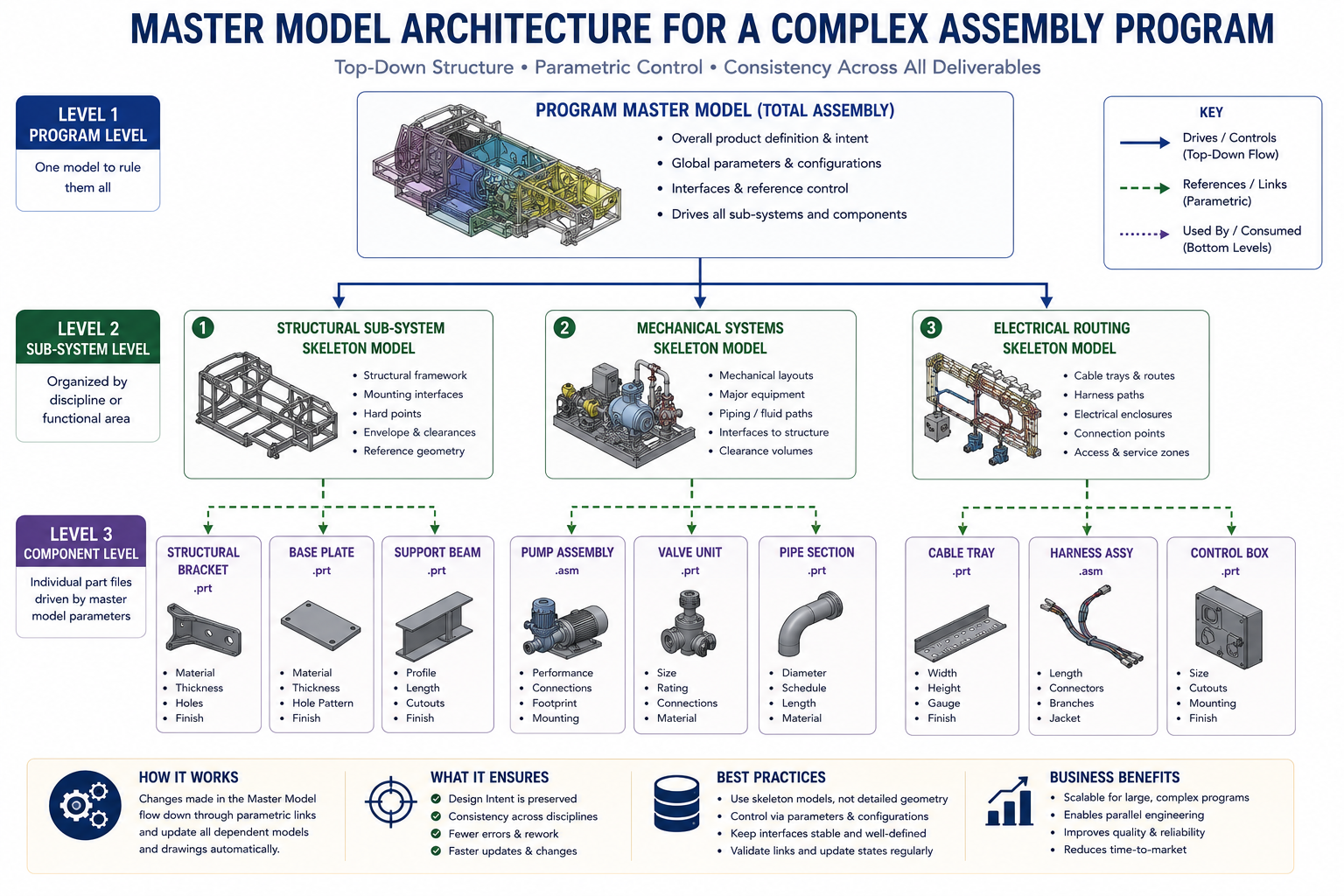
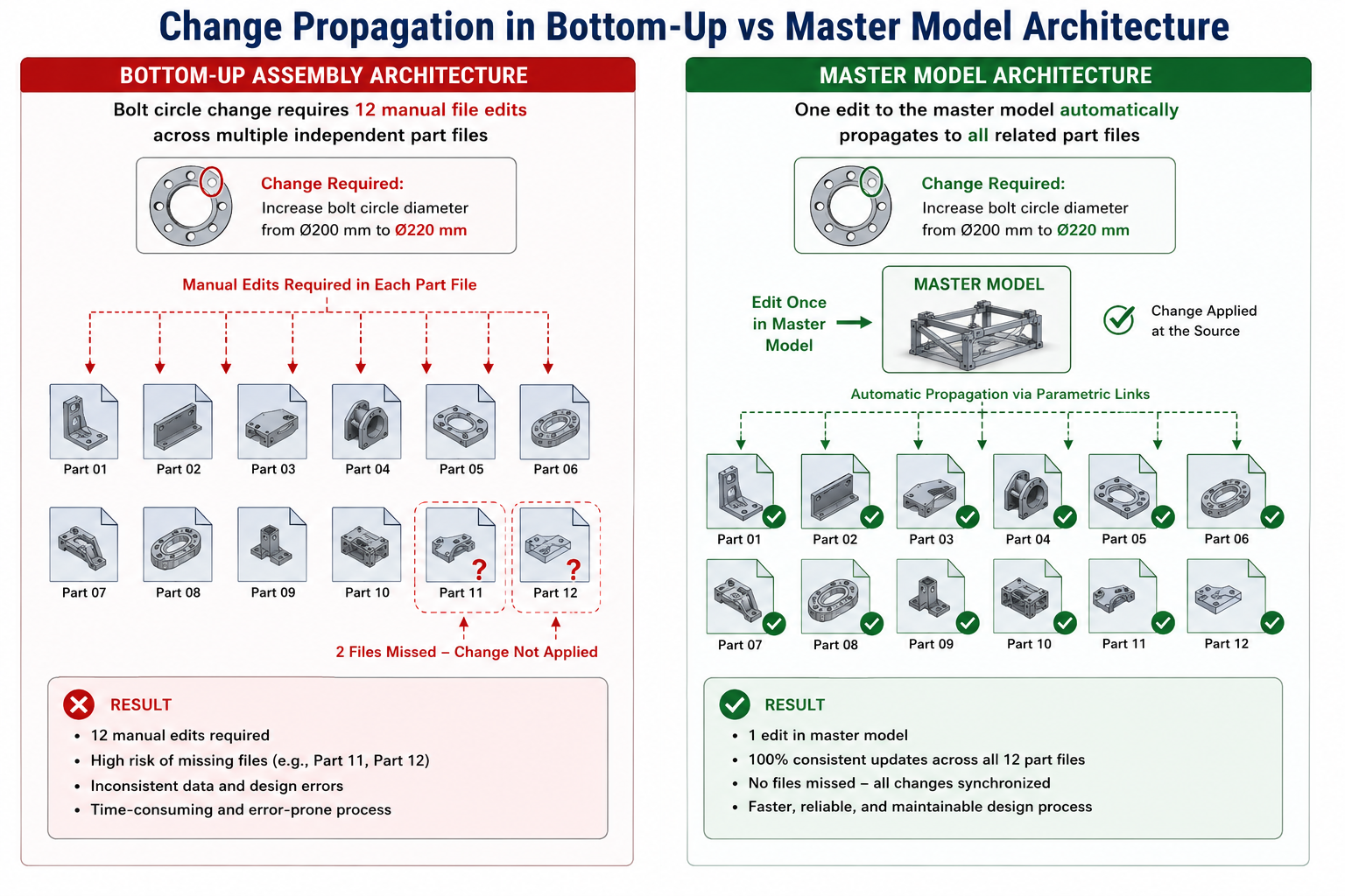
The most immediately apparent benefit is change propagation: a design change that affects ten components in the program requires one edit to the master model rather than ten edits to ten separate part files. The less immediately obvious but ultimately more valuable benefit is interface integrity: because all components that share an interface draw that interface geometry from the same master model source, the interface is inherently consistent. There is no scenario in which two components define the same interface differently and diverge over time.
Master Models vs. Skeleton Models: Understanding the Distinction
The terms master model and skeleton model are often used interchangeably, but they describe slightly different concepts that are worth distinguishing precisely. A skeleton model is a lightweight geometry file that contains reference geometry only: planes, axes, curves, and key points that define the layout and interfaces of an assembly, with no solid bodies and no mass properties. Its purpose is to serve as a spatial reference framework.
A master model is a broader concept that encompasses skeleton models but extends to any controlling file that drives dependent geometry. A master model may contain solid bodies (for multi-body modeling approaches where components are extracted from a solid master), surface bodies (for surface-driven product designs), or purely reference geometry (in which case it is functionally identical to a skeleton).
In Creo, the formal skeleton model is a specific file type with a special designation. In SolidWorks, the closest equivalent is a layout sketch or master sketch in a part file or an in-context driven assembly. In NX, the WAVE Geometry Linker establishes similar inter-part relationships without requiring a dedicated skeleton file type.
For the purposes of this article, master model refers to the broader architecture: any CAD design in which a designated controlling file or set of files defines the critical shared geometry that drives all dependent components. The specific implementation varies by platform, but the architectural principle and the benefits it delivers are consistent.
The Reference Architecture: What the Master Model Contains
A well-designed master model does not contain everything. It contains only the information that must be consistent across multiple components or sub-systems. Putting too much in the master model creates an unwieldy file that is slow to open and difficult to manage. Putting too little defeats the purpose by leaving critical interfaces undefined at the system level.
The appropriate content of a master model for a complex mechanical assembly includes:
- Critical interface surfaces and planes: the mounting faces, parting surfaces, and contact planes between major sub-systems that must be consistent for the assembly to close correctly
- Envelope geometry: the maximum space claim of each sub-system, defined as a volume or set of bounding surfaces that establishes what space each sub-system owns and what space is available to adjacent sub-systems
- Key dimensions and parameters: the hole patterns, bolt circles, shaft diameters, channel widths, and other dimensions that appear in multiple components and must be changed synchronously when any one of them changes
- System-level axes and reference planes: the coordinate system and primary reference planes that establish a consistent orientation framework for the entire program
- Kinematic constraints: the motion limits, travel envelopes, and clearance volumes for moving components within the assembly, defined at the system level so all fixed components can verify clearance against them
| What is a master model in CAD? A master model in CAD is a designated controlling file that defines critical interface geometry, envelope dimensions, and system-level parameters for a complex assembly. All component files in the program reference the master model parametrically, so design changes made in the master propagate automatically to every dependent component. Master models enable large engineering teams to work concurrently on different sub-systems with confidence that their interfaces will be compatible at integration. |
The Five Core Benefits of Master Model Architecture on Large Programs
The case for master models on large engineering programs is not made by theory alone. It is made by specific, measurable benefits that affect program schedule, cost, quality, and team productivity in ways that are directly traceable to the master model architecture. The following five benefits represent the consistent outcomes reported by engineering teams that have implemented master modeling on complex programs.
Benefit 1: Interface Integrity by Design
The most costly category of engineering failure in complex assembly programs is interface mismatch: two components, designed by different engineers or different teams, that do not fit together at their shared interface. These mismatches are discovered during integration, which is the most expensive stage of development to make corrections.
A published study in product development literature finds that design changes made during integration cost 10 to 100 times more than the same changes made during detailed design, due to the cascading effect on tooling, procurement, testing, and schedule.
Master model architecture eliminates this failure mode for all interfaces that are defined in the master. When two components both draw their shared interface from the master model, they are by construction geometrically compatible. The interface surface is not defined twice by two engineers who must agree: it is defined once in the master and referenced by both.
Interface mismatch at that boundary is geometrically impossible unless the master itself is wrong, and the master is controlled by a governance process that prevents unauthorized changes.
A tier-one automotive supplier implementing master model-based design for a new transmission housing program reported that first-assembly fit issues dropped by 78 percent compared to the previous program, which was designed using bottom-up assembly without a master model. The reduction was directly attributable to the master model architecture eliminating the category of interface mismatch errors that had been the dominant source of assembly failures on the previous program.
Benefit 2: Concurrent Engineering at Full Team Scale
Bottom-up assembly design serializes the work: mechanical team finishes before systems team starts, electrical team waits for mechanical to define routing space, manufacturing engineering cannot begin fixture design until all parts are final.
This serialization is not inefficiency through poor planning. It is a structural consequence of not having a defined spatial framework within which teams can work concurrently. Without a master model, there is nothing reliable for the second team to reference until the first team’s work is complete.
A master model breaks this serialization. Once the master model is established with the envelope geometry, key interfaces, and system-level parameters, every sub-system team has a defined spatial contract within which they can work simultaneously. The mechanical team knows the space available to them. The electrical team knows where they cannot run cables.
The manufacturing engineering team knows the part envelope and can begin fixture and tooling design in parallel with the detailed design phase.
In a program without a master model, these teams work sequentially, and the total program schedule is the sum of all phases. In a program with a master model, the teams work concurrently, and the total program schedule is approximately the length of the longest critical path.
For a program with four major sub-system teams, the theoretical schedule compression from full parallelism is up to 75 percent of the sequential duration. In practice, dependencies and integration requirements limit the actual compression, but programs consistently achieve 30 to 50 percent schedule compression on the concurrent engineering phases through master model-enabled parallelism.
Benefit 3: Change Propagation That Scales With Program Complexity
In a bottom-up assembly, a single change to a critical interface dimension requires finding and updating every component that references that dimension. For a program with 200 components that share a common mounting bolt pattern, changing the bolt circle diameter means visiting 200 files. Each visit carries the risk of missing the change in one file, of introducing an error during the manual update, or of the change triggering a downstream failure in that file’s feature tree that requires additional repair.
The manual update burden scales linearly with the number of affected components. The error probability scales with the update burden.
With a master model, the same change requires one edit: the bolt circle diameter parameter in the master model. Every component that references the master model’s bolt pattern updates automatically on the next rebuild. The engineer does not need to identify which components are affected, does not need to open each one individually, and does not risk missing a component or introducing an error during manual update. The change propagation is complete, consistent, and automatic.
For a medical device design team that rebuilt their primary platform using master model architecture, a customer-requested envelope size change that would have taken three weeks in their previous bottom-up workflow was completed in two days. The master model defined the envelope geometry. All 87 components in the assembly referenced it.
Changing the master envelope dimensions triggered a full rebuild that updated all 87 components simultaneously. Two days of verification and review replaced three weeks of manual updates.
Benefit 4: Design Intent Preserved at the System Level
Individual component design intent, the parametric relationships within a single part file, is preserved by the techniques covered in the article on reducing CAD rework through design intent. But system-level design intent, the reasoning behind why components relate to each other the way they do, is rarely captured anywhere in a bottom-up assembly. It exists in the engineer’s memory, in meeting notes, and in email threads, but not in the CAD model itself.
A master model makes system-level design intent explicit and self-documenting. The critical interfaces are in the master model, named and organized according to what they represent. The envelope geometry is in the master, with dimensions driven by parameters named after the requirements they encode.
When a new engineer joins the program six months in, they can open the master model and understand the system-level geometry of the entire program in one place, without needing to synthesize that understanding from two hundred individual part files.
This preserved design intent has compounding value: it accelerates onboarding of new team members, it makes the design explainable during customer and regulatory reviews, and it provides the geometric traceability that regulated industries require to demonstrate that design requirements are reflected in the physical geometry of the product.
Benefit 5: Reduced Rework Cost at the Most Expensive Stage
The cost of rework in product development follows a well-documented exponential increase as a program progresses. A design change made at the concept phase costs dollars. Made during detailed design, it costs hundreds. Made after tooling release, it costs tens of thousands. Made during production ramp-up, it can cost hundreds of thousands when tooling changes, scrap, retest, and schedule impact are totaled.
Master models reduce rework cost by moving error detection to the earliest possible stage: the moment the master model is built, all interface errors that would have been discovered at integration are visible and correctable.
This is not a theoretical benefit. It is the direct consequence of the interface integrity benefit described above. Interface mismatches that are caught at the master model stage, weeks or months before any physical parts exist, cost only engineering time to fix. The same mismatches caught at first prototype build cost parts, tooling, assembly labor, test resources, and schedule. The master model’s primary economic value is the elimination of the latter category.
Master Model vs Bottom-Up Assembly: A Scenario-by-Scenario Comparison
The decision to use master model architecture versus a conventional bottom-up assembly approach is not a blanket choice for or against either method. It depends on the nature of the program, the team structure, and the specific design challenges involved. The following comparison provides decision criteria for ten common engineering scenarios.
| Design Scenario | Bottom-Up Assembly | Master Model / Top-Down | Winner |
| First interface fit check | Late (after all parts exist) | Immediate (interfaces in master) | Master Model |
| Late-stage design change affecting 20+ parts | 2+ weeks (manual updates per part) | Hours (propagates from master) | Master Model |
| Parallel team working concurrently on sub-systems | Risk of interface mismatch at integration | Teams work from shared master interfaces | Master Model |
| Simple product, single engineer, few parts | Faster to start | Overhead not justified | Bottom-Up |
| Reusing existing standard components unchanged | Copy files directly, place in assembly | Skeleton references add unnecessary complexity | Bottom-Up |
| Design exploration before concept is set | Flexible, minimal commitment | Skeleton setup before concept is premature | Bottom-Up |
| Complex assembly, 50+ parts, multiple engineers | High integration risk, rework-heavy | Controlled interfaces, disciplined change | Master Model |
| Assembly with critical interface dimensions | Mating errors found at build | Errors caught at master model stage | Master Model |
| PDM-managed long-lifecycle product | Individual file control sufficient | Master model enables system-level change control | Master Model |
| Regulated product requiring design traceability | Tracing to root cause is difficult | Master model is single traceable origin of all geometry | Master Model |
The pattern in this table reflects the fundamental economics of master model architecture: the benefits are proportional to complexity and team size, while the overhead is fixed. For a simple product designed by one engineer, the master model overhead is not justified by the benefits. For a complex program with multiple concurrent engineering teams and many shared interfaces, the master model is not an optimization. It is a prerequisite for the program to succeed at schedule and cost targets.
Platform-Specific Implementation: How Master Models Work in Your CAD Tool
The architectural principle of master modeling is consistent across platforms, but the specific tools, file types, and workflows differ significantly. Understanding your platform’s implementation is essential for building a master model that leverages the platform’s strengths and avoids its specific failure modes.
| CAD Platform | Master Model Tool | Skeleton/Linker Feature | Multi-Level Hierarchy | Performance Tool | Key Strength |
| PTC Creo | Skeleton Model (.prt skeleton) | Publish Geometry / Copy Geometry | Yes (nested skeletons) | Simplified Representation | Industry-leading skeleton architecture, formal skeleton part type |
| Siemens NX | Master Part / Assembly Context | WAVE Geometry Linker | Yes (multi-level WAVE) | Lightweight Reference Sets | Most powerful inter-part linking, used in aerospace/auto programs |
| Dassault CATIA V5/V6 | Skeleton (Structured Design) | External Parameters / Publication | Yes (Structured Design) | CGR Visualization Mode | Standard in aerospace (Airbus, Boeing CATIA programs) |
| SolidWorks | Master Sketch / Layout Sketch | In-Context References | Limited (2 levels practical) | SpeedPak / Lightweight Mode | Accessible, but external reference management requires discipline |
| Autodesk Inventor | Skeleton Part / iAssembly | Derived Part / Adaptivity | Limited | Substitutes (simplified) | Good for mid-complexity programs, integrates with Vault PDM |
| Autodesk Fusion 360 | Master Component / Assembly Context | External References | Limited | Proxy Components | Cloud-native, suited for smaller teams, real-time collaboration |
| Siemens Solid Edge | Skeleton Model | Inter-Part Copy | Partial | Simplify Part | Strong for SME-level programs, synchronous technology integration |
PTC Creo: The Formal Skeleton Architecture
Creo’s skeleton model is a formal, platform-recognized file type rather than an ordinary part file used as a master. When you create a skeleton in Creo, the system assigns it a special designation that distinguishes it from regular parts in the assembly tree. The skeleton is excluded from mass properties calculations, excluded from the BOM, and excluded from clash analysis because it is not a physical component. It is infrastructure.
The Publish Geometry and Copy Geometry features in Creo are the mechanisms by which skeleton geometry is transferred to component parts. Publish Geometry in the skeleton identifies specific curves, surfaces, planes, and axes that are available for external reference. Copy Geometry in the component part creates a parametric link to those published elements. The component’s features then reference the copied geometry, which updates whenever the skeleton changes.
Creo’s multi-skeleton capability supports hierarchical master model architectures: a program-level skeleton, sub-system skeletons that reference the program skeleton, and component parts that reference the sub-system skeletons. Changes propagate top-down through this hierarchy automatically.
This architecture is used in complex aerospace and defense programs where hundreds of engineers work concurrently on different sub-systems, each owning their sub-system skeleton while the program team controls the top-level skeleton.
Siemens NX: The WAVE Geometry Linker
WAVE (What-if Alternative Value Engineering) is NX’s inter-part linking technology, and it is arguably the most powerful master model implementation available in any commercial CAD platform. WAVE creates associative geometry links between any two parts or assemblies in the same NX session, with full parametric update propagation across any number of levels in the linking hierarchy.
Unlike Creo’s skeleton-based approach, WAVE does not require a designated skeleton file type. Any NX part can be the source of WAVE-linked geometry for any other NX part. The WAVE Geometry Linker creates a link that can transfer individual faces, edges, curves, datums, or entire bodies between parts, with the linked geometry updating in the target part whenever the source changes.
Multiple levels of WAVE linking are fully supported, allowing a program-level master to drive sub-system models that in turn drive component models through a chain of WAVE links.
WAVE is the standard master model technology in NX-based aerospace and automotive programs. Airbus uses NX with WAVE-based master models on major structural programs. Several major automotive OEMs and tier-one suppliers use WAVE-linked skeleton architectures for body-in-white, powertrain, and chassis programs.
The technology’s strength is its flexibility: it does not impose a fixed architectural pattern, allowing each program to structure its linking hierarchy according to its own organizational and technical requirements.
SolidWorks: In-Context References and Layout Sketches
SolidWorks implements master model concepts through in-context references: features in one part file that reference geometry from another part in the same open assembly. An in-context extrude can reference a face in a different component. An in-context cut can be sized by a dimension in the layout sketch. These references create the parametric linkage that makes the master model pattern work.
The layout sketch approach uses a part file (typically named Master.sldprt or Layout.sldprt) containing only sketch geometry: reference lines, circles, and points that define the system-level geometry. This file is placed as the first component in the top-level assembly and used as the reference source for all other components’ in-context features. It is functionally equivalent to a Creo skeleton but without the formal platform designation as a skeleton type.
The critical failure mode for SolidWorks master models is the out-of-context reference. When a part with in-context references is opened outside the context of the assembly that contains the master model file, SolidWorks cannot resolve the references. Features turn gray in the feature tree with a warning icon. If the engineer makes changes to the part in this out-of-context state, SolidWorks may break the in-context reference permanently.
Managing this requires strict discipline: components with in-context references must always be opened through the assembly, never as standalone files.
Autodesk Inventor: Skeleton Parts and Adaptivity
Inventor supports master modeling through two mechanisms: the skeleton part approach (similar to Creo’s skeleton, a designated reference geometry file placed in the assembly) and adaptivity, which allows a part’s features to automatically adjust their dimensions based on the mating geometry of other components in the assembly.
Adaptivity is more automated than explicit skeleton referencing but less controlled, and it can produce unexpected behavior in complex assemblies when multiple adaptive relationships create conflicting constraints.
For complex programs in Inventor, the skeleton part approach is more reliable than adaptivity. A skeleton part is created as an ordinary part file that contains only sketch geometry and reference planes, placed in the assembly as the first component, and referenced by other components through the Derive Part feature or through in-context editing.
The workflow is similar to SolidWorks but with Inventor-specific tools for managing the external reference structure.
Building a Multi-Level Master Model Hierarchy for Enterprise Programs
For programs at the scale of aircraft, vehicles, complex industrial machines, or large medical systems, a single master model file is not architecturally sufficient. The information needed at the program level (the overall vehicle envelope, the primary structural axes, the system-level kinematic travel) is different from the information needed at the sub-system level (the engine bay envelope, the powertrain mounting interfaces), which is different again from what is needed at the component level (the specific bolt pattern on a specific bracket).
Enterprise-scale programs require a hierarchical master model architecture: multiple skeleton or master files organized in a parent-child hierarchy, each level defining the information appropriate to its scope, with lower levels referencing higher levels through parametric links. Changes made at the program level propagate automatically through all levels of the hierarchy to every dependent component.
The Three-Level Hierarchy: Program, Sub-System, Component
The most common hierarchical architecture for large programs uses three levels. At the top, the program-level master model defines the overall envelope, primary coordinate systems, system-level kinematic travel, and the space claims assigned to each major sub-system. This file is owned by the chief engineer or lead systems engineer and is the most tightly controlled file in the program.
At the second level, sub-system skeleton models define the detailed geometry within each sub-system’s space claim. The powertrain sub-system skeleton defines the engine mounting interfaces, the transmission attachment points, the cooling system envelope, and the exhaust routing space.
The structural sub-system skeleton defines the primary frame geometry, the cross-member locations, and the attachment interfaces to adjacent sub-systems. Each sub-system skeleton references the program master for its envelope and primary interfaces, and adds the detail geometry needed within its own scope.
At the third level, individual component parts reference the sub-system skeleton for the interfaces and constraints relevant to their design. A bracket references the frame attachment geometry from the structural sub-system skeleton.
A heat shield references the exhaust envelope from the powertrain sub-system skeleton. The component’s features are driven by the sub-system skeleton, which is in turn driven by the program master.
Change Propagation Through the Hierarchy
The parametric chain through the hierarchy means that a change at any level propagates automatically to all levels below it. A change to the program-level master updates all sub-system skeletons that reference it, which in turn updates all component parts that reference those sub-system skeletons. For a large program with three skeleton levels and several hundred component parts, this automatic propagation is the capability that makes large-scale concurrent engineering tractable.
The propagation is not instantaneous in large assemblies. A full rebuild of a three-level hierarchy with hundreds of dependent parts can take minutes in complex programs. Performance management is essential for making this workflow practical. Every major CAD platform includes tools for managing rebuild performance in hierarchical master model architectures: Simplified Representations in Creo, Reference Sets in NX, SpeedPak in SolidWorks.
Using these tools to control which geometry is loaded and rebuilt during the iterative design phase, reserving full rebuilds for milestone checks, keeps the architecture usable during active design work.
Multi-Level Master Model File Naming Convention |
Master Model Governance: Ownership, Change Control, and Access
A master model without governance is a liability rather than an asset. If any engineer can modify the master model at any time, the change propagation that makes the master model valuable becomes the mechanism by which a single careless edit triggers unwanted geometry updates in hundreds of dependent component files, potentially undetected until first article inspection.
Master model governance establishes clear rules for who can change the master, how changes are authorized, how affected teams are notified, and how the integrity of the master is verified after each change. The governance framework is not bureaucracy. It is the control system that converts the master model’s raw propagation power into a reliable engineering tool.
Defining Master Model Ownership
Every level of the master model hierarchy must have a designated owner: a specific engineer or engineering role that is responsible for the integrity, currency, and governance of that file. For the program-level master, the owner is typically the chief engineer or lead systems engineer. For sub-system skeletons, the owner is the sub-system lead. Ownership means responsibility for authorizing changes, not necessarily for making them
The owner’s responsibilities include: reviewing all proposed changes before they are made, assessing the downstream impact of proposed changes on all teams that reference the file, notifying all affected teams before implementing changes, verifying the integrity of the master after changes are made, and ensuring that the revision history accurately records what changed and why.
These responsibilities are manageable when the master model has a clear, single owner. They become unmanageable when ownership is informal or collective.
The Change Authorization Process
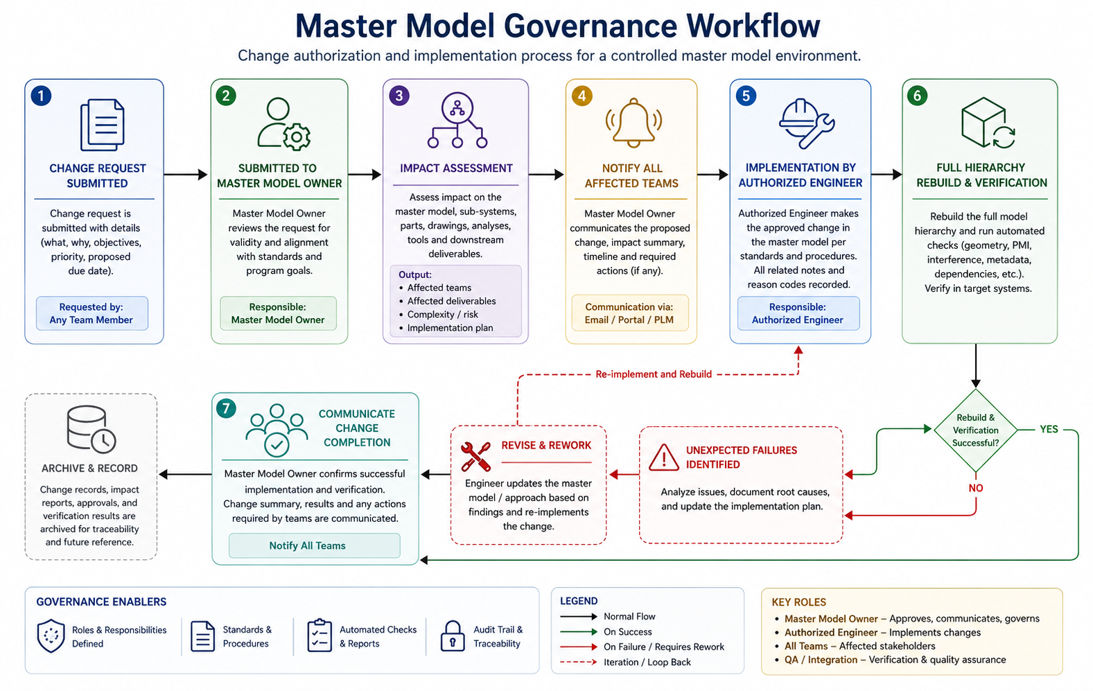
Changes to the master model should follow a lightweight but formal change authorization process. Unlike a full Engineering Change Order, which may be appropriate for released production-level masters, the process during the design phase should be fast enough not to impede design progress while controlled enough to prevent unauthorized changes from propagating to dependent teams.
A practical change authorization process for a master model during the design phase includes:
- Change request: The requesting engineer describes the proposed change and its technical justification. Takes ten minutes to document.
- Impact assessment: The master model owner identifies which teams and which files will be affected by the change. Takes thirty minutes to one hour depending on program complexity.
- Notification: All affected teams are notified of the pending change with enough advance notice to prepare for the rebuild, typically 24 to 48 hours.
- Implementation: The change is made to the master model by its owner or under the owner’s direct supervision.
- Rebuild and verification: The full hierarchy is rebuilt and inspected for unexpected failures or unintended geometry changes in dependent components.
- Communication: All affected teams are notified that the change is implemented and are asked to verify their components rebuilt correctly.
This six-step process takes one to two days for a well-managed master model. The two-day overhead per master model change sounds significant until it is compared to the alternative: uncontrolled changes that silently break dependent components and are discovered days or weeks later when those components are used.
PDM Integration for Master Model Version Control
Master model files must be under PDM version control with stricter settings than ordinary component files. In SolidWorks PDM, this means configuring the skeleton file to require an elevated permission level for checkout, ensuring that only authorized engineers can edit it. In Creo Windchill, the skeleton model should be in a controlled state that prevents editing without an explicit lifecycle state transition approved by the owner.
In NX with Teamcenter, the master model file should be on a controlled lifecycle that triggers a change management workflow for any state transition that permits editing.
The revision history of the master model is the chronological record of all interface and system-level changes made to the program. It should document not just what changed but why: the requirement change, the customer input, the structural analysis result, or the interference detection that drove the master model revision.
This documentation transforms the master model’s revision history into a design rationale record that is invaluable for program reviews, regulatory submissions, and the engineering memory that new team members need to understand how the program reached its current state.
Managing the External Reference Problem in SolidWorks Master Models
SolidWorks engineers who implement master model workflows consistently encounter the same challenge: external reference management. When a component file contains in-context references to a master model or to other components in the assembly, those references are only resolvable when the entire assembly is open and all referenced files are accessible.
Opening the component file in isolation produces the out-of-context warning, and any changes made in the out-of-context state risk breaking the reference permanently. This is not a flaw in SolidWorks. It is a fundamental property of parametric inter-file referencing. The reference is a relationship between two files. Resolving it requires both files to be present.
The challenge is that engineers naturally want to open individual part files for quick edits without loading the entire assembly context, and the master model architecture makes this simple habit potentially destructive.
The Out-of-Context Reference Failure Mode
When SolidWorks cannot find a referenced file, it marks the affected features with an out-of-context indicator. If the engineer proceeds to edit the part while out-of-context, SolidWorks must decide what to do with features that depend on the missing reference: it typically freezes the feature at its last known state.
If the engineer then modifies a dimension that overrides the in-context reference, the override becomes permanent and the parametric link to the master model is severed. The next time the assembly is opened with all files present, the feature does not update from the master model because the link has been broken by the out-of-context edit
This silent link breakage is the most damaging failure mode in SolidWorks master model workflows. The component looks correct in the assembly because the last-known master model geometry was used. But it will not update when the master model changes, defeating the entire purpose of the master model architecture.
Systematic Prevention of Out-of-Context Edits
Prevention requires both technical and procedural measures:
- Technical: Configure the SolidWorks external reference settings to lock out-of-context features rather than allowing them to be edited. Under Tools > Options > External References, set the option to not allow modification of out-of-context features. This makes the out-of-context state obviously non-functional and forces engineers to open the assembly before editing.
- Technical: Use the SolidWorks Open in context option, available by right-clicking a component in the assembly tree, to open the component file within the assembly context without loading the full assembly graphics. This provides the component editing experience with the external references resolved.
- Technical: Configure SpeedPak or Simplified Representations for the master model assembly so that the full assembly can be opened quickly without loading all component details, making the assembly context the natural starting point for component editing.
- Procedural: Establish a team rule that components with external references are never edited through Windows Explorer double-click or through the Recent Files list, which opens them without assembly context. All editing of externally-referenced components begins by opening the parent assembly first.
- Procedural: Include an external reference audit in the pre-release checklist for any component with in-context features. The audit verifies that all external references are resolved, no references are dangling or out-of-context, and all dependent features are updating correctly from the master model.
Master Models in Regulated Industries: Aerospace, Medical, and Defense
Regulated industries apply additional requirements to master model governance beyond what product development programs in general industry typically need. In aerospace (AS9100), medical devices (ISO 13485), and defense (MIL-SPEC design configuration management), the geometric definition of a product must be traceable, controllable, and auditable to a degree that requires specific master model architecture decisions.
Design Traceability Through the Master Model
In regulated product development, design traceability means the ability to demonstrate that every geometric feature in the released product design can be traced back to a specific requirement.
For products designed with a master model architecture, the master model itself becomes the primary traceability artifact: the critical interfaces and envelope geometry in the master are driven by specific design requirements, and the master model’s revision history documents how requirements changes translated into geometry changes over the program’s development history.
This traceability is difficult or impossible to establish in a bottom-up assembly where critical interfaces are defined independently in individual component files with no system-level reference. When a regulatory auditor asks why the mounting bolt pattern has a specific diameter and PCD, the answer must trace back to a design requirement.
In a master model, that answer is in the master model parameter definition: the bolt circle diameter is driven by a named parameter that was set to the value derived from the load calculation in the design record. In a bottom-up assembly, the engineer who chose that value may no longer be with the organization.
Configuration Control for the Baseline Master Model
Aerospace and defense programs use the concept of a design baseline: a formally released configuration of the design at a specific program milestone (Preliminary Design Review, Critical Design Review, production release) that becomes the reference configuration for all subsequent changes. In a master model architecture, the baseline includes the master model files at their revision levels at the baseline date, along with all dependent component files.
The PDM system must be configured to capture and restore the complete baseline configuration, including all skeleton levels and all dependent component files, as a coherent snapshot. When a change is proposed after baseline, it must be processed through the Engineering Change Order workflow, and the change’s impact must be assessed against the baseline configuration.
The master model’s parametric structure makes this impact assessment tractable: the owner of the master can identify all downstream files affected by a proposed master model change by querying the PDM system’s where-used analysis for the master model file.
Multi-Site Programs and Distributed Master Model Access
Large regulated programs often involve engineering teams at multiple geographic locations, different organizations, or different subsidiaries. A master model architecture for these programs must address how the master model is accessed by teams that are not co-located and may be operating under different PDM environments or organizational security requirements.
The standard approach for multi-site programs is to designate the program management organization as the custodian of the program-level master model, with other organizations accessing it through controlled read-only copies or through a federated PLM environment that maintains synchronization between sites.
Changes to the master follow the change authorization process described in the governance section, with the additional step of distributing the changed master to all site repositories before requesting dependent teams to rebuild their components.
When Master Models Break Down: Failure Modes and How to Prevent Them
Master model architecture delivers its benefits when it is implemented correctly and governed consistently. When either condition fails, the master model does not simply underperform: it can actively harm the program by creating a false sense of interface control while the actual interfaces drift out of alignment due to broken references, unauthorized edits, or an overgrown master that no one can maintain.
The Overgrown Master Model
The most common master model failure mode on programs that start with good discipline is the overgrown master. The master model starts with the appropriate content: critical interfaces, envelope geometry, key dimensions. Over time, as the program evolves, engineers add more geometry to the master because it is convenient to put shared information in one place. The master grows. It becomes slower to open.
Rebuilds take longer. Engineers start opening components without the assembly context to avoid the rebuild time. External references begin breaking. The master model, which was supposed to be the lightweight coordination layer, has become the heaviest file in the program.
Prevention requires scope discipline enforced by the master model owner: a clear, written definition of what belongs in the master and what does not, reviewed at each major program milestone and enforced through the change authorization process.
When an engineer requests to add geometry to the master, the owner asks: does this geometry need to be shared across two or more sub-systems? If yes, it belongs in the master or the appropriate sub-system skeleton. If it is specific to one component or one sub-system, it belongs in that component or sub-system skeleton, not in the master.
The Unresolvable Reference Chain
In multi-level skeleton hierarchies, long chains of parametric references can create performance and reliability problems. A program-level master drives a sub-system skeleton, which drives a component skeleton, which drives three component parts. Each link in this chain adds rebuild time and each link is a potential point of failure if any file in the chain moves, is renamed, or has its reference broken.
Keep reference chains as short as possible. A component that needs information from the program-level master should reference it directly (through its sub-system skeleton, not through two or three intermediate skeletons) to minimize the chain length.
Every additional link in a reference chain adds fragility and rebuild time without adding design control value. Design the skeleton hierarchy to provide the right information at each level rather than building long pass-through chains that carry information from the top level all the way down without modification.
The Abandoned Master Model
The most damaging failure mode is the master model that is abandoned mid-program because the governance overhead became unmanageable, the master model owner left the program, or the program transitioned to a faster-paced development phase where waiting for change authorization felt too slow. When the master model is no longer maintained, teams stop referencing it.
References go out of date. The master model no longer reflects the actual design. Engineers continue to reference it because it is in the assembly, but the references are stale and the propagated geometry is wrong.
Prevent abandonment by designing governance for the program’s pace: lighter processes for early concept development, heavier processes for post-baseline design. If the change authorization process is taking two weeks in a phase where the design changes daily, the process is wrong for the phase. Streamline it.
If no one has budget to maintain the master model, the program needs to recognize master model maintenance as a funded activity rather than an assumed background task. A master model that is 90 percent maintained is a liability: teams will not know which references are current and which are stale, and the false confidence of having a master model is more dangerous than having no master model at all.
Frequently Asked Questions
Q: What is a master model in CAD?
A master model in CAD is a designated controlling file that defines the critical interface geometry, envelope dimensions, and system-level parameters for a complex assembly or engineering program. All component files in the program reference the master model parametrically through features that update automatically when the master model changes.
The master model ensures that all components sharing a critical interface draw that interface from the same geometric source, preventing interface mismatch errors and enabling controlled, automatic propagation of design changes across all dependent components.
Q: What is the difference between a master model and a skeleton model in CAD?
A skeleton model is a type of master model that contains only reference geometry (planes, axes, curves, and points) without solid bodies, mass properties, or a BOM entry. In PTC Creo, skeleton models are a dedicated file type with special system behavior. A master model is a broader concept that can also include solid or surface bodies for multi-body design workflows. In SolidWorks and Autodesk Inventor, master models are typically standard part files using layout or master sketches, since no dedicated skeleton file type exists.
Q: How does a master model reduce design changes in large engineering programs?
A master model simplifies design changes by automatically propagating updates to all linked components through parametric references. A single change in the master model updates every dependent part during assembly rebuild, eliminating repetitive manual edits. This reduces engineering effort, prevents inconsistencies, and minimizes the risk of missed updates.
Q: What is the WAVE Geometry Linker in Siemens NX and how does it support master modeling?
WAVE is Siemens NX’s inter-part linking technology that enables associative master model workflows by automatically propagating geometry changes between linked parts. It supports hierarchical multi-level links without requiring a dedicated skeleton file, making it widely used in large aerospace and automotive programs.
Q: What are the risks of using in-context references in SolidWorks master models?
The biggest risk is out-of-context reference failure, where editing a linked part outside its assembly can permanently break its connection to the master model. This prevents future automatic updates and is avoided by opening parts through the assembly and restricting out-of-context editing.
Q: How should master models be governed in a large engineering team?
Effective master model governance requires clear ownership, controlled change approval, and PDM-based version control with restricted editing permissions. All changes should be documented with their justification and impact, with governance becoming more formal as the project matures.
Q: When should you use a master model versus a bottom-up assembly approach?
Use a master model for complex, multi-team projects with shared interfaces, frequent design changes, or traceability requirements. Use a bottom-up assembly for small, simple projects, reusable standard components, or early-stage concept development.
Conclusion:
The difference between a large engineering program that integrates smoothly and one that spends months recovering from interface mismatches and design change rework is rarely a difference in individual engineering skill. It is a difference in system-level design architecture. Master models are that architecture.
By defining critical interfaces, envelope geometry, and system-level parameters in a single controlled source that all teams reference, master models eliminate the category of interface mismatch errors entirely for any interface they control. By propagating changes automatically through the hierarchy, they make large-scale design changes manageable rather than overwhelming. By enabling concurrent engineering, they compress program schedules in ways that no improvement to individual engineer productivity can match.
The investment in master model architecture is real: the planning time to design the skeleton hierarchy, the discipline to govern it correctly, the learning curve for teams implementing it for the first time. But it is a one-time investment per program that delivers returns throughout the entire program lifecycle.
The programs that make this investment at the beginning consistently outperform those that attempt to retrofit organization onto a bottom-up assembly that grew organically, because retrofit is always more expensive than planning.
Start with the program-level master model. Define the critical interfaces. Assign ownership. Establish the change authorization process before the first change is needed. Then build the sub-system skeletons and onboard the component teams. The architecture will feel like overhead in the first two weeks and like infrastructure for the rest of the program.
Strengthen your CAD engineering practice with our guides on multi-body modeling techniques, design intent and parametric modeling, CAD file management for complex programs, and managing CAD data translation for multi-platform teams.