A precision machined aluminium housing had been passing inspection at the machining supplier for six months. Every inspection report showed every feature within tolerance. When the housings arrived at assembly, roughly one in eight needed rework because a critical bore wasn’t perpendicular to the mating surface within the functional requirement.
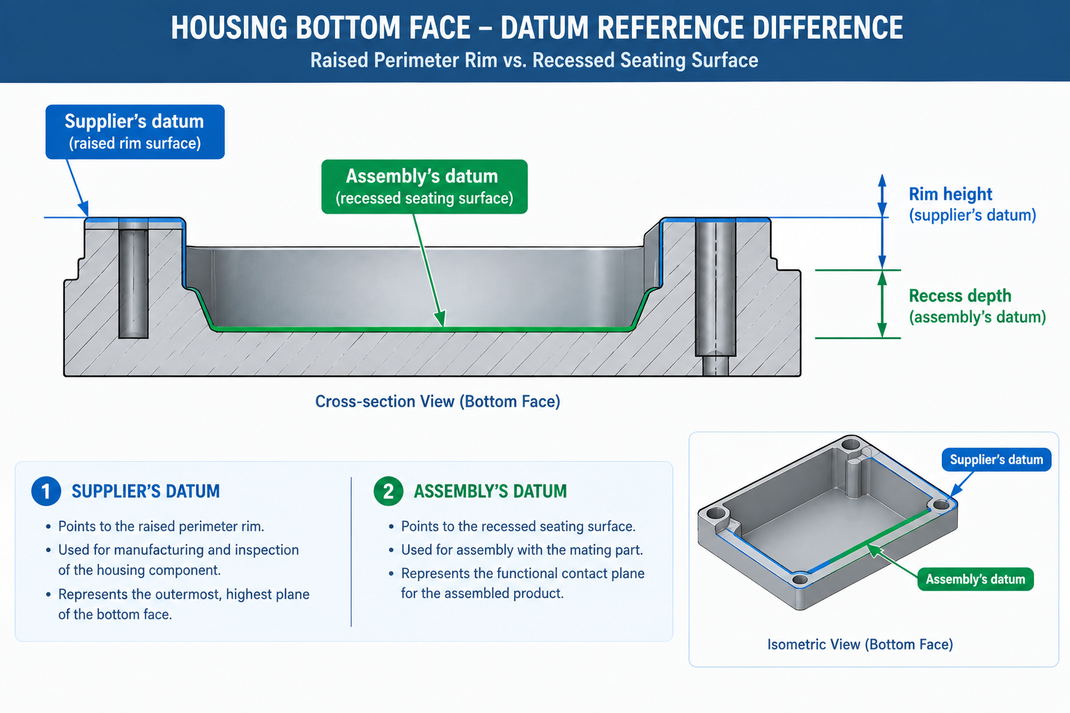
The supplier’s CMM report showed perpendicularity of 0.04mm to datum A, within the 0.05mm callout. The assembly team’s CMM showed 0.09mm to their datum. The drawing specified datum A as “bottom face.” The supplier measured from the largest bottom face. The assembly team measured from the functional seating surface, a recessed area 12mm smaller on each side, with a step around the perimeter.
| Quick answer: Two legitimate interpretations of “bottom face” produced two legitimate measurements, one part that assembled correctly and one that didn’t. The supplier did nothing wrong, and neither did the assembly team. The drawing had specified a datum that was correct in principle but incomplete in definition, and that gap propagated silently through six months of production before assembly revealed it. Good datum selection follows six criteria, stability, accessibility, functional relevance, geometric quality, repeatability, and independence, and functional relevance overrides all the others: the datum must match the surface that actually locates the part in assembly, not the surface that’s easiest to measure. |
Datum selection is the foundation of GD&T. The tolerance values on a feature control frame are only as meaningful as the datums they reference, and a technically achievable tolerance becomes functionally worthless if the datum structure doesn’t reflect how the part is actually located in assembly.
What a Datum Actually Is and Why the Definition Matters
A datum in GD&T is a theoretically exact geometric reference: a perfect plane, axis, or point, derived from actual part surfaces but not identical to them. The actual surface it’s derived from is the datum feature. This distinction matters because real surfaces have form error, a flat datum feature has waviness and roughness, but the datum derived from it is treated as a perfect plane for measurement purposes.
In practice, the datum is simulated by the inspection fixture: a granite surface plate simulates a perfect flat datum plane, a precision mandrel simulates a perfect cylindrical axis. The quality of this simulation determines how accurately features can be measured relative to it. A granite plate with 0.002mm flatness simulates a perfect plane far more accurately than the 0.03mm datum feature on the part, which is what makes it a valid simulator. If the simulator’s own form error rivals the tolerances being measured, the measurement loses credibility regardless of the CMM’s resolution.
The Datum Reference Frame: Constraining All Six Degrees of Freedom
A rigid body has six degrees of freedom: three translational and three rotational. Defining a body’s position and orientation completely means constraining all six. This is what a three-datum reference frame does: datum A constrains three (a flat surface typically constrains translation in Z and rotation about X and Y), datum B constrains two more, and datum C constrains the last one.
When the datum reference frame is incomplete, one or more degrees of freedom stay unconstrained. An under-constrained part can shift or rock in the fixture, and the measured position of any feature depends on which of many possible positions the part happened to settle in during setup. This produces inspection results that vary between measurements of the same part, making it impossible to tell whether variation comes from the part or the setup. The housing story was exactly this: “bottom face” wasn’t complete enough to fully constrain the part, and different teams set up from different interpretations of it.
Six Criteria for Selecting a Good Datum Feature
Applying these six criteria in order usually identifies which surfaces should be datums. The order matters: functional relevance is the most important, and a datum that fails it shouldn’t be used regardless of how well it scores on the others.
| Criterion | Good Datum Feature | Poor Datum Feature | Test to Apply |
|---|---|---|---|
| Stability | Large flat surface with well-separated contact points; precision bore with adequate length-to-diameter ratio | Small area, curved, or thin edge surface likely to flex under contact | Press lightly on the candidate surface: does it rock or shift? |
| Accessibility | First surface machined, usable throughout all operations without repositioning | Surface hidden in a pocket or requiring the part to be turned after locating on other datums | Can all referenced features be measured while resting stably on this datum? |
| Functional relevance | The surface or axis that actually contacts the mating part in service | A surface convenient in CAD but absent from the assembly interface | In the assembled product, which surface actually contacts the mating part? |
| Geometric quality | A surface with adequate flatness/roundness, much tighter than the tolerances it controls | A wavy, rough, or burred surface that introduces its own variation | Measure the candidate’s own form; it should be 5-10x tighter than the tightest tolerance referencing it |
| Repeatability | Easy to clean, unaffected by normal handling | Prone to burrs, nicks, or requiring special preparation | Run the same part three times on the same fixture; do results match? |
| Independence | Three datums each constraining different degrees of freedom | Two parallel flat surfaces used as primary and secondary, constraining the same direction | After locating on primary, check what freedom remains; secondary should stop what primary cannot |
Functional Relevance: The Criterion That Overrides All Others
Functional relevance is the criterion violated most often in practice, and the violations produce exactly the housing-failure scenario from the opening story. A designer who picks datum surfaces because they’re large, flat, and easy to measure in CAD, without checking whether they’re the surfaces that actually locate the part in assembly, builds a datum scheme that’s geometrically sensible but functionally disconnected from the product’s real behaviour.
The test is physical: hold the part and place it into the assembly the way it would actually be placed. Which surfaces contact first? Which constrain movement as the part seats? Those are the functional datum candidates, following the datum rules defined in ASME Y14.5. The last surface to contact before the part is fully seated is the tertiary datum; the first is the primary. This physical walk-through, done at the drawing stage rather than discovered on the shop floor, is the single most effective way to build a datum scheme reflecting functional reality.
Datum Schemes for Six Common Part Types
What works for a prismatic block doesn’t work for a shaft, and what works for a sheet metal bracket may not work for a cast housing.
| Part Type | Primary (A) | Secondary (B) | Tertiary (C) | Common Mistake |
|---|---|---|---|---|
| Prismatic machined block | Largest flat face (sits on this in assembly/fixture) | Perpendicular face with most contact area | Third perpendicular face | Making secondary parallel to primary, giving no independent constraint |
| Rotating shaft | Central axis (simulated by precision V-blocks/mandrels) | One end face (prevents axial translation) | Optional keyway/flat (constrains rotation) | Using the shaft diameter surface instead of the axis; diameters carry form error the axis doesn’t |
| Flanged housing, bore-located | Central bore axis (accepts the locating pin/shaft) | Mounting face (seats against mating flange) | One mounting hole/slot | Making the large flat face primary, which is convenient but not how the part is actually located in assembly |
| Sheet metal bracket | Largest flat panel face | Nearest long edge or slot | One mounting hole | Using bend flanges as primary; they’re often not flat and introduce large datum error |
| Thin disc or washer | One flat face (constrains tilt) | Outer diameter or bore (centres in-plane) | Rarely needed for symmetric parts | Specifying OD as primary; a thin disc’s OD is a poorly defined short cylinder |
| Cast part, complex geometry | Machined pad or boss (specifically machined as the datum reference) | Machined bore or pin location | Second machined bore/slot | Using the raw cast surface as a datum; its form error is far too large for tight tolerances |
The Cast Part Special Case
Cast parts pose the most challenging datum selection problem in manufacturing. Raw cast surfaces carry form error orders of magnitude larger than any reasonable manufacturing tolerance: surface roughness of Ra 6 to 25 microns, flatness deviation of 0.5 to 3mm over large surfaces, and variation between castings from the same mould driven by solidification effects rather than tool geometry. Using a raw cast surface as a datum means every measurement referenced to it inherits all of that variation.
The standard solution is machining datum pads: small, precisely machined areas designated specifically as datum reference surfaces and machined to tight flatness before any other features are cut. These pads are typically marked on the drawing with a datum symbol and sometimes with a physical stamp on the casting. All functional features are then measured from these machined pads, not the raw cast surface, which is only used as the rough locating reference for the first machining operation that creates the pads.
Datum Error Sources: Why Measurements Disagree Between Teams
The most frustrating inspection disputes happen when both parties have the same drawing, use the correct datum labels, and produce measurements they each consider correct, yet those measurements disagree. These disputes almost always trace to one of six sources.
| Error Source | How It Affects Measurement | Typical Magnitude | Prevention |
|---|---|---|---|
| Datum surface form error | Part rocks/tilts on fixture; different contact combinations give different measurements | +/-0.05 to 0.5mm | Specify and inspect the datum’s own form tolerance; hold it 5-10x tighter than what it controls |
| Datum contamination (chips, burrs) | Foreign material lifts the part locally, creating artificial tilt | +/-0.1 to 1.0mm | Clean datum surfaces before every measurement; specify burr-free in drawing notes |
| Datum simulation error (fixture wear) | Fixture locators wear over production runs; the simulated datum drifts | +/-0.01 to 0.1mm accumulating | Calibrate fixtures periodically; measure locators with reference gauge pins |
| Datum accessibility compromise (proxy datum) | Inspector substitutes an accessible surface for the specified one | +/-0.05 to 0.3mm | Design datums for setup accessibility; use datum targets if accessibility is genuinely limited |
| Datum sequence error | Measuring from datum B before establishing datum A leaves the part unconstrained | Variable, can be large | Establish datums in A-B-C order; train inspectors on datum priority |
| Thermal expansion during measurement | Long parts or temperature differences change measured dimensions | +/-0.01mm per °C per 100mm (steel); +/-0.023mm (aluminium) | Measure at 20°C reference temperature; allow parts to stabilise before measuring |
Datum Contamination: The Error That Looks Like a Process Problem
Datum contamination is one of the most common measurement error sources in machining environments, and one of the most easily confused with a genuine process capability problem. A chip lodged under the primary datum surface lifts one corner of the part off the fixture, tilting it by an amount proportional to chip height and datum contact area. Every feature measured from that tilted datum is displaced by an amount depending on its distance from the chip and the tilt angle.
The signature is a systematic bias in a cluster of features on one side of the part, with the opposite side measuring correctly. A chip under one corner tilts the part about a line through the other datum contacts, shifting features on the elevated side one way and features on the opposite side the other. When an inspection report shows this pattern, the first diagnostic step is cleaning the datum face and re-measuring before concluding the process is out of control. Three minutes of cleaning is faster and cheaper than a nonconformance report over a problem that never existed in the part.
Machining Sequence: Preserving the Datum Reference Frame Across Operations
The datum reference frame isn’t just a drawing tool; it’s a manufacturing tool. Used correctly, it ensures each machining operation builds on the accuracy of the previous one. The correct sequence machines datum features first and uses them as the reference for everything downstream, so every feature cut in the sequence has the most accurate possible positional relationship to every other feature.
| Operation | Datum Used | Purpose | Why This Order |
|---|---|---|---|
| 1: Face mill primary datum surface (A) | Rough part surface (pre-datum) | Create the precision flat reference for all subsequent operations | Must machine A first, it’s the foundation for all other measurements |
| 2: Square secondary datum surface (B) to A | Datum A (freshly machined) | Machine B perpendicular to A within its own tolerance | B can only be accurately squared to A after A is machined |
| 3: Machine tertiary datum surface (C) perpendicular to A and B | Datums A and B | Complete the three-datum reference frame | All three datums must exist before any functional features are cut |
| 4: Machine all functional features | Datum A, B, C, the complete frame | Produce holes, pockets, bosses in one setup referenced to the completed frame | Eliminates accumulated setup error; features in the same setup relate most accurately to each other |
| 5: Inspect all functional features and datum surfaces | Datum A, B, C, same as machining | Verify tolerances relative to the datum reference frame | Inspection must use the same frame as machining or results won’t correspond to how the part was made |
The Single-Setup Principle
The most accurate machined parts come from a single setup using the finished datum reference frame, since single-setup machining eliminates the repositioning error that accumulates between setups. When a part needs features on multiple faces, the ideal sequence machines all datum surfaces first, even if that requires an initial rough setup, then machines all functional features in one setup from the completed datum frame.
In practice, most parts can’t be completely machined in a single setup, but the principle still gives clear direction: minimise the number of setups, always machine datums before functional features, and use the datum surfaces as the reference for all subsequent setups. Each deviation from the single-setup ideal introduces error that compounds across the tolerance stack-up of features cut in different setups.

Datum Targets: When a Whole Surface Is Not a Good Datum
Sometimes a natural datum candidate is too large, irregular, or poorly controlled for the entire surface to serve as a datum. A large casting’s bottom face may have waviness that makes one contact point differ from another by half a millimetre. A sheet metal bracket’s mounting face may be distorted by forming stresses. Using the full surface as a datum in these cases introduces all of that variation into every measurement, making tight tolerances impossible to hold.
Datum targets solve this. Instead of designating the whole surface as datum A, the designer designates specific points, lines, or limited areas as the contact locations, and only those specific spots touch the fixture locators. The datum is defined by those contact points rather than the full surface, eliminating the rest of the surface’s form error from the measurement. Datum targets are specified by a target symbol on the drawing giving the contact point’s location and, for area targets, the size and shape of the contact area.
Datum targets are most common on castings and forgings with large raw-surface form error, sheet metal parts with forming distortion, and large machined parts that can’t be guaranteed flat across their entire surface. The fixture implementing datum targets uses precision spherical contact points or flat pads at the specified locations rather than full-surface contact, and that matched pair of drawing and fixture is what makes the scheme repeatable across all production and inspection setups.
Worked Examples
Correcting the housing datum scheme: The housing from the opening story specified datum A as “bottom face,” interpreted differently by the supplier (full bottom face including the rim) and the assembly team (the recessed central seating surface). Neither interpretation was wrong given the drawing’s language; the drawing used natural language where a GD&T symbol was needed.
The correction applied the datum feature symbol directly to the recessed seating surface, with a flatness callout of 0.02mm defining its own form requirement, plus a note clarifying that datum A was the recessed surface, not the perimeter rim. Adding datum targets specifying the three contact points of the fixture locators ensured both the supplier’s inspection fixture and the assembly team’s CMM setup contacted the same specific areas.
After the revision, both facilities measured perpendicularity relative to the same surface at the same contact points, the first inspection after revision produced matching results between them, and the rework rate dropped to zero. Six months of assembly rework traced to two words, “bottom face,” replaced by a symbol, a flatness callout, and three datum target coordinates.
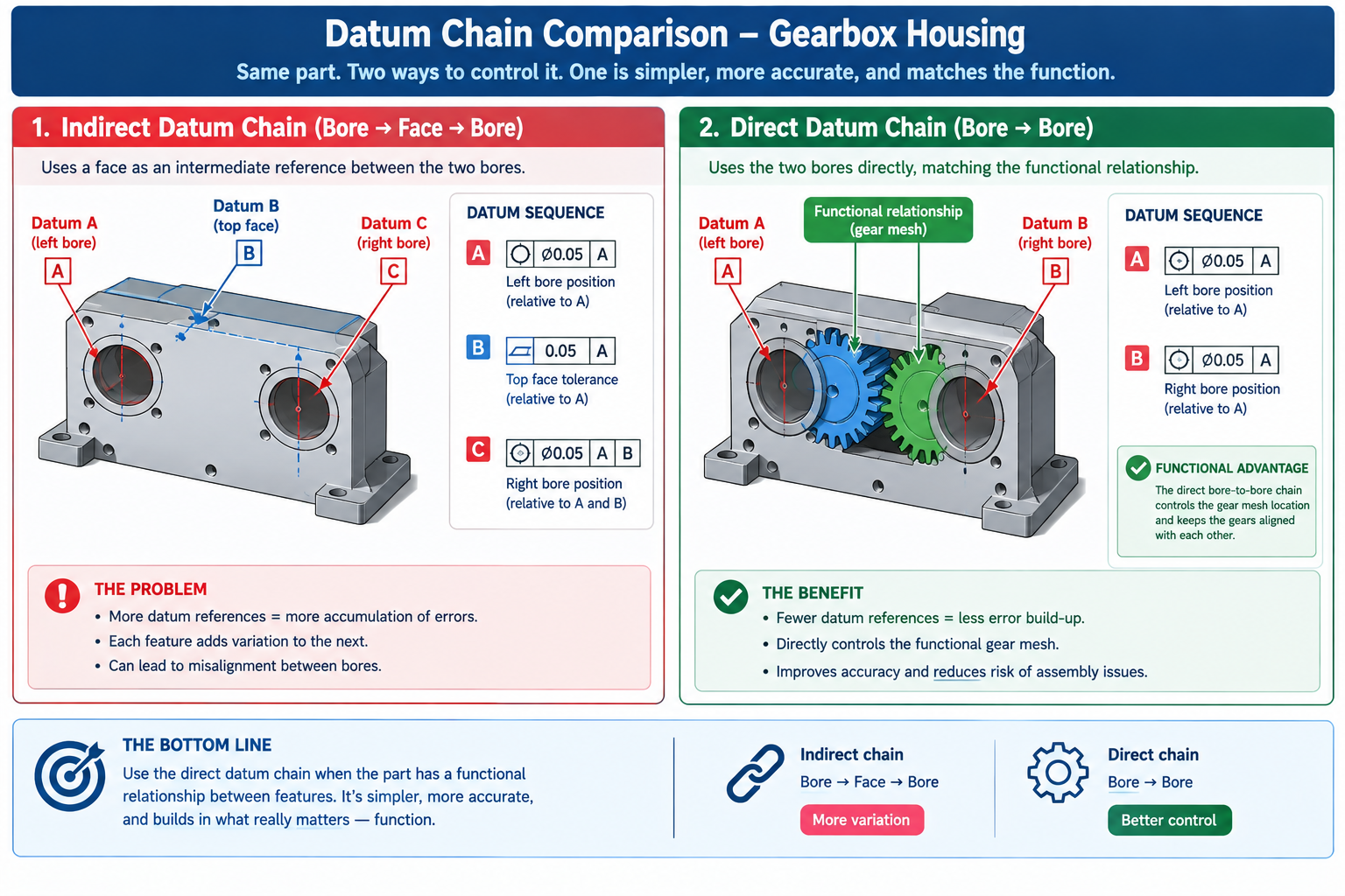
The shaft housing with a bore datum: An aluminium gearbox housing had a main shaft bore and a secondary shaft bore whose centre distance and parallelism were critical for gear mesh quality. The original drawing used the flat base mounting face as datum A and specified the secondary bore position relative to it. The machine shop measured from the base face and held conformance; the gearbox assembly facility measured bore-to-bore and found parallelism varying up to 0.12mm beyond spec, against a noise requirement of 0.03mm parallelism over 100mm.
The root cause was a datum that didn’t match the assembly’s functional geometry. Gear mesh quality is governed by the relationship between the two shaft axes, not by each axis’s relationship to the housing base, which is functionally the mounting datum for the gearbox to the vehicle. Specifying bore positions relative to the base face created an indirect chain (bore to face to bore) when the direct relationship (bore to bore) was what actually mattered.
The redesign used the primary shaft bore axis as datum A, with the secondary bore specified directly by centre distance and parallelism relative to it, keeping the base face as a separate datum for the mounting features that actually relate to it. Two separate datum reference frames, one for gear mesh geometry and one for mounting geometry, each matching the functional relationship it controls. After the revision, the machining setup located the secondary bore from the primary bore, matching what actually governs gear noise, and the assembly facility’s measurements agreed with the supplier’s. Gearbox noise improved and the measurement disputes stopped.
Frequently Asked Questions
How do I know which surface should be the primary datum? The primary datum should be the surface that most completely locates the part in its assembly function, practically the surface that contacts first and provides the most stable constraint when seated in its assembly or inspection fixture. For prismatic parts, usually the largest flat face. For shaft-based components, the axis of the main locating bore or shaft. For flanged parts located by a bore, the bore axis. The test is physical: place the part into the assembly as it would actually be assembled and identify the first surface to contact the mating part.
Can the same drawing have different datum reference frames for different features? Yes, and it’s sometimes the correct approach for complex assemblies where different feature groups relate to different functional references. A gearbox housing may have one datum reference frame for gear-set bore geometry and a separate one for mounting features. These are different functional relationships that don’t need to share a datum scheme. Each feature control frame carries its own datum reference, as long as each references datums appropriate for the functional requirement it controls.
What is a datum target and when should I use one? A datum target is a specific point, line, or limited area on a datum feature designated as the actual contact location for the inspection fixture. Only the targeted locations contact the fixture, so the datum is defined by those specific contacts rather than the full surface with all its form error. Use datum targets when the datum feature is a cast or forged surface with significant form error, a large sheet metal panel where the full surface isn’t reliably flat due to forming stresses, or a complex shape where only specific areas can practically serve as locating references.
Why does the order of datums in a feature control frame matter? The order (A, B, C left to right) defines the priority in which they constrain the part during measurement setup: A is applied first, removing three degrees of freedom, then B removes two more, then C removes the last one. If applied in the wrong order, the part may be constrained differently than intended, producing different results. This is why the datum order must match the physical assembly sequence, primary first, secondary second, tertiary third, and a correctly set-up CMM program establishes each datum in that order before measuring any feature.
What is the difference between a datum feature and a datum? A datum feature is the actual physical surface or axis on the part, carrying form error, a flat surface isn’t perfectly flat, a bore isn’t perfectly round. A datum is the theoretically exact plane, axis, or point derived from the datum feature and used as the measurement reference. The datum is perfect by definition; the datum feature is real and imperfect. In practice, the datum is simulated by the inspection fixture, and the quality of that simulation determines how accurately the datum is established.
How does poor datum selection cause parts to pass inspection and fail assembly? When the inspection datum doesn’t match the assembly datum, the measurement confirms the part conforms to the drawing’s datum scheme, but that scheme doesn’t reflect how the part is actually located in assembly. The part can be perfectly within tolerance relative to the inspection datum while out of specification relative to the assembly’s functional datum, because those two datums aren’t the same surface.
This is exactly what happened in both worked examples here: both teams measured the same physical part correctly against their own references, and only aligning the inspection datum with the assembly functional datum, following the practical measurement guidance in Meadows’ Geometric Dimensioning and Tolerancing, fixes it.
Key Takeaways
The housing dispute from the opening story cost six months of production output before anyone identified the cause. The gearbox noise problem required redesigning both the drawing and the machining setup on an established production programme. Both were caused by datum selections that were technically valid under a loose reading of the drawing but functionally disconnected from what the assembly actually required, not by manufacturing error, measurement error, or tolerance error.
The six selection criteria, functional relevance especially, are the engineering discipline that prevents these failures. A datum that passes all six will produce consistent measurements at the machining supplier, at incoming inspection, and at the assembly station, because all three are measuring from the same functional reference that defines how the part is actually used.
Get the datums right and the tolerances, however tight, are measurements of things that matter. Get the datums wrong and even a perfectly made part can fail inspection, or pass inspection and fail assembly, depending entirely on which surface each team happened to measure from.