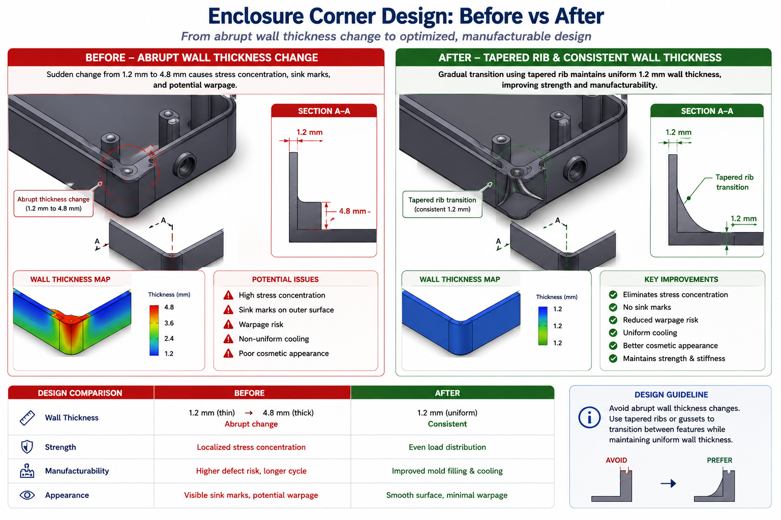
An injection-moulded enclosure looked fine on screen. Wall thickness ranged from 1.2mm to 4.8mm across the part because the designer hollowed out a solid model without tracking where the resulting walls changed thickness. Nobody caught it in CAD review, since the review checked fit and function, not wall uniformity.
The tooling got cut. First shots showed sink marks over every thick section and a warp across the lid that threw the snap-fit tabs out of alignment by half a millimetre. Fixing it meant reworking tool steel and revalidating fit. The change cost eleven thousand dollars and pushed launch back six weeks.
| Quick answer: Design for manufacturability (DFM) is the set of process-specific constraints that turn a geometrically correct CAD model into a part that can actually be produced, at target cost, without surprises after tooling is committed. The highest-leverage checks are wall thickness uniformity, draft angles, internal fillet radii, and tolerances specified no tighter than function requires. None of these are engineering skill gaps; they’re a missing systematic check against how the part will actually be made. |
This guide covers the four processes most engineers actually work with: injection moulding, CNC machining, sheet metal forming, and assembly. It includes a 20-item checklist with priority ratings, four reference tables with the numbers you need at the CAD stage, and worked examples showing how a DFM review changes a part before it reaches a tool shop.
The 20-Point DFM Checklist
This master checklist spans all four process families and is built to scan quickly during a design review. Critical items cause part failure, tooling damage, or major rework if missed. High items cause significant cost or schedule impact. Medium items are good practice that controls cost without being make-or-break.
| # | Checklist Item | Process | Cost Impact if Ignored | Priority |
|---|---|---|---|---|
| 1 | Minimum wall thickness meets process capability | Moulding, die casting | Sink marks, incomplete fill; scrap up 10-30% | Critical |
| 2 | Uniform wall thickness throughout the part | Moulding, casting, sheet metal | Warping, sink marks, internal stress | Critical |
| 3 | Draft angle applied to all vertical faces | Moulding, casting, forging | Part sticks in mould; drag marks; tooling damage | Critical |
| 4 | Generous fillets at internal corners | All processes | Stress concentration, sink marks, crack initiation | Critical |
| 5 | Hole diameter-to-depth ratio within process limits | Machining, moulding, casting | Drill wander, tool breakage, incomplete fill | High |
| 6 | Avoid undercuts unless side-action tooling is budgeted | Moulding, die casting | Requires slides/lifters; tooling cost +20-50% | Critical |
| 7 | Standard fastener sizes and thread specs used | Assembly, machining | Custom fasteners cost 3-10x standard | High |
| 8 | Tolerances specified only as tight as needed | Machining, all processes | Cost increases exponentially per tightened tolerance | Critical |
| 9 | GD&T datums match assembly and inspection method | Machining, inspection | Unmeasurable tolerances; assembly issues | High |
| 10 | Symmetric or self-locating parts | Assembly | Incorrect assembly; warranty and rework cost | High |
| 11 | Minimize part count through consolidation | Assembly, all processes | Each part adds time, inventory, failure points | High |
| 12 | Avoid dissimilar materials without joining plan | Assembly, welding, bonding | Galvanic corrosion; CTE mismatch failure | Critical |
| 13 | Bend radius meets minimum per material/thickness | Sheet metal | Cracking at bend; unpredictable springback | Critical |
| 14 | Features kept clear of bend lines (2-3x thickness) | Sheet metal | Distortion near bend; feature tolerance lost | High |
| 15 | Machined features accessible without special tooling | CNC machining | Custom fixtures or multiple setups needed | High |
| 16 | Parting line positioned to minimize flash | Die casting, sand casting | Excess flash removal labor; cosmetic defects | Medium |
| 17 | Weld joint design matches process capability | Welding/fabrication | Poor penetration, distortion, rework | Critical |
| 18 | Surface finish specified only where necessary | Machining, finishing | Unnecessary polishing operations add cost | Medium |
| 19 | Design supports automated inspection | Quality/inspection | Manual inspection required; slower, less repeatable | Medium |
| 20 | Reviewed against supplier’s process capability data | All processes | Design exceeds shop capability; late redesign | Critical |
| How to use this checklist: Run it at the CAD stage, before any drawing goes out for quoting or tooling. It works best as a joint review between the design engineer and someone with shop-floor or supplier experience, since the reference table numbers are starting points, not universal constants. Every supplier has their own capability data, and asking for it directly is the only way to know your actual limits. |
Injection Moulding: Where Wall Thickness Decides Everything
Injection moulding is unforgiving about wall thickness in a way that surprises engineers coming from machining or sheet metal backgrounds. Molten plastic fills a cavity and has to cool before ejection. Thick sections cool slower than thin ones, and that mismatch is the root cause of most defects people associate with cheap-looking plastic parts: sink marks, warping, internal voids.
The fix is almost always the same: keep wall thickness as close to uniform as possible, within the range the resin and geometry can support. Where a thicker section is unavoidable, like a screw boss, taper into it gradually instead of stepping straight from thin to thick.
| Design Parameter | Recommended Value | What Happens If Violated |
|---|---|---|
| Nominal wall thickness | 1.0-3.5mm most thermoplastics; 0.5-1.0mm minimum for engineering resins | Thicker: sink marks, voids. Thinner: incomplete fill, high pressure |
| Wall thickness uniformity | Variation under 10-15% of nominal | Differential cooling causes warping and internal stress |
| Draft angle | 1-2° minimum for smooth surfaces; 3-5° for textured | Drag marks, part sticking, ejector pin stress |
| Internal corner radius | 0.5x wall thickness minimum; ideal 0.75-1.0x | Stress concentration (Kt up to 3+), fracture initiation |
| Rib thickness | 50-60% of adjacent wall thickness at base | Ribs over 60-75% cause visible sink marks opposite |
| Boss wall thickness | 60% of nominal wall; taper thinner at tip | Thick bosses sink and crack; thin bosses strip threads |
| Hole diameter-to-depth | Through holes up to 4-6x diameter; blind holes 2-3x | Deep core pins deflect, causing wall variation or breakage |
| Minimum feature size | 0.4-0.5mm standard; 0.15-0.25mm with precision tooling | Features below capability fail to fill or break during ejection |
Draft Angle: The Rule Everyone Forgets Until the First Shot
Draft angle is the small taper on vertical walls that lets the part release from the mould without the steel scraping the surface on the way out. A part with zero draft looks completely normal on screen, sometimes cleaner than one with draft applied. The problem only shows up at the tool shop, or on the first production shot, when the part either won’t release or comes out scarred with drag marks.
Apply draft as one of the first steps once a surface is finalised, not as an afterthought. Most CAD packages include a draft analysis tool that colour-codes the model relative to pull direction. Run it before calling the design done. Textured surfaces need roughly an extra degree of draft for every 0.025mm of texture depth, since texture adds friction during ejection.
Ribs and Bosses: The Sink Mark Trade-off
Ribs add stiffness without adding bulk, which is why they show up everywhere in plastic part design. A rib is effectively a local thickness increase where it meets the wall. If that local thickness gets too close to the wall’s own thickness, a sink mark appears on the opposite face as material pulls in during cooling. Keeping the rib base at roughly half to sixty percent of the adjacent wall is the standard fix, worth knowing by heart.
Screw bosses add a second consideration: the boss needs to survive repeated screw insertion without cracking, which pushes toward a thicker wall, while a thicker wall pushes toward sink marks. The usual resolution keeps the boss wall around sixty percent of nominal thickness and adds a gusset rib connecting it to the nearest structural wall.
CNC Machining: Designing Around Tooling and Fixturing
Machining feels more forgiving than moulding since material is removed rather than formed, with no mould to fill or shrink unevenly. But it has its own constraints, rooted in cutting tool geometry and the practical limits of holding a part securely while cutting. Both are easy to overlook in CAD, since a 3D model doesn’t care how a tool would physically reach a pocket or how the part sits in a vice.
The most common machining DFM mistake is calling out a sharp internal corner in a pocket. Every end mill is a cylinder, so it leaves a radius in every internal corner it cuts. A sharp 90-degree internal corner forces the machinist into a tiny, fragile custom tool or a separate EDM finishing step, either of which adds cost that a slightly larger radius avoids for free.
| Design Parameter | Recommended Practice | Cost Impact |
|---|---|---|
| Internal corner radius | Match standard end mill sizes: 1.5mm, 3mm, 6mm, 10mm | Custom small-radius tooling adds 30-100% machining time |
| Hole tolerance and finish | Standard reamed/drilled (+/-0.05 to 0.1mm) unless function requires tighter | Each tightened level adds 15-40% cost |
| Thread depth and type | Standard series (UNC, UNF, metric coarse); blind hole depth 1.5-2x diameter | Custom thread forms require special long-lead tooling |
| Pocket depth-to-width | Keep below 4:1 for standard end mills | Long-reach tooling cuts feed rate 30-60% |
| Datum and fixturing access | Flat, accessible reference surfaces for workholding | Custom fixtures cost $2,000-$20,000 and add weeks |
| Number of setups required | Minimize machine orientations needed | Each additional setup adds 20-40% cost |
| Tool access for deep features | Verify standard-length tool reaches without collision | EDM workaround costs 5-20x standard milling |
| Thin wall machining | Minimum 0.5mm wall for rigid materials with support | Thin walls need slower feeds, multiple passes: 2-4x cycle time |
Setups: Every Reorientation Costs Time and Accuracy
A CNC machine only reaches features from the orientation it currently holds the part in. Features cut from four different sides mean the part gets removed, flipped, and realigned four times, and each of those setups adds machine time, operator labor, and a small amount of alignment error between features cut in different orientations.
This doesn’t mean avoiding multi-sided parts; plenty of functional designs genuinely need features on more than one face. It means that between two functionally equivalent designs, the one needing fewer setups will be meaningfully cheaper and faster. A quick mental walk-through of how the part sits in a vice and how a tool reaches each feature catches a surprising number of these issues before they hit a quote.
Sheet Metal: Bend Lines Are Where Things Go Wrong
Sheet metal parts start as flat stock that gets cut and bent into shape, and almost every design problem traces back to a bend line. Material doesn’t like being bent sharply. Bend it too tight relative to thickness and it cracks on the outside of the bend, especially in stainless steel or hardened aluminum tempers with less ductility than mild steel.
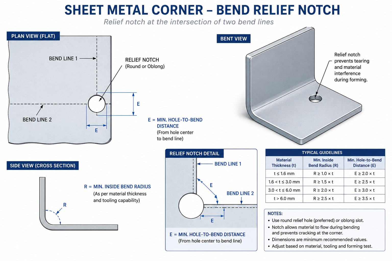
Minimum bend radius scales roughly with material thickness. A radius equal to material thickness is a safe baseline for mild steel and most aluminum alloys, with stainless and harder tempers needing more. Where two bend lines meet at a corner, a relief notch is needed at the intersection before bending, or the corner tears as both folds try to occupy the same material at once.
| Design Parameter | Recommended Practice | Common Mistake |
|---|---|---|
| Minimum bend radius | ~1x material thickness for mild steel/aluminum; 2-3x for harder tempers | Specifying a zero-radius bend, which cracks |
| Bend relief at corners | Relief notch at least equal to material thickness | Omitting relief causes tearing at bend intersections |
| Hole-to-bend distance | 2.5-3x thickness plus bend radius | Placing holes too close causes distortion during forming |
| Hole-to-edge distance | 1.5-2x material thickness | Holes too close to edge cause bulging or tearing |
| Minimum flange length | 3x thickness plus bend radius | Flanges too short for tooling to grip inconsistent bend angle |
| Tab and slot fit | Slot width = tab thickness + 0.1-0.2mm clearance | Zero-clearance designs ignoring cutting tolerance |
| Countersink compatibility | Match standard tooling angle (82° or 90°) | Countersink deeper than material allows, breaking through |
Features Near a Bend Line Move More Than You Expect
Holes, slots, and cutouts placed too close to a bend line get pulled out of position as material deforms during forming. Keep functional features at least two and a half to three times the material thickness from the nearest bend line, with extra margin if hole tolerance is tight. This is one of the more common reasons a sheet metal part comes back from its first form with mounting holes that no longer line up, and it’s entirely avoidable by checking feature-to-bend distance before the flat pattern is finalised.
Tolerances: The Hidden Cost Multiplier
Tolerance specification hides a lot of unnecessary cost, because tightening a tolerance doesn’t add cost linearly, it adds it disproportionately, and that relationship isn’t obvious from looking at a drawing. A dimension at commercial tolerance might cost a few cents to hold. The same dimension at precision tolerance might cost several times that, not because the machine runs slower, but because tighter tolerances usually require additional operations, more careful fixturing, environmental control, and inspection.
The habit worth building: for every toleranced dimension, ask what actually breaks if the tolerance were twice as loose. If the honest answer is nothing, the tolerance is tighter than needed and adding cost with no functional benefit.
| Tolerance Class | Typical Range (linear, mm) | Relative Cost | Achievable By |
|---|---|---|---|
| General/commercial | +/- 0.25 to 0.5 | 1.0x (baseline) | Standard milling, turning, sheet metal forming |
| Precision | +/- 0.05 to 0.15 | 1.5-2.5x | Standard CNC with normal process control; reamed holes |
| High precision | +/- 0.01 to 0.05 | 3-6x | Temperature-controlled CNC; CMM verification |
| Ultra-precision | +/- 0.002 to 0.01 | 8-20x | Grinding, honing, jig boring; climate-controlled metrology |
| Flatness (general) | 0.05-0.1mm over 100mm | 1.5-2x vs no callout | Standard machining and finishing |
| Position (general) | +/- 0.1-0.25mm diameter zone | 1.5-3x vs basic dimension | CNC with standard fixturing |
| Surface finish, as-machined | Ra 1.6-3.2 μm | 1.0x (baseline) | Standard milling and turning |
| Surface finish, ground/polished | Ra 0.1-0.8 μm | 3-10x | Grinding, lapping, polishing |
GD&T Datums Should Match How the Part Is Actually Used
Geometric dimensioning and tolerancing gives a precise language for describing how a feature can vary, following the ASME Y14.5 standard for dimensioning and tolerancing, but it only helps if the datum structure reflects how the part is actually held during machining, measured during inspection, and mated during assembly. A datum scheme that looks correct on paper but doesn’t match any of those real-world references creates a part that can pass inspection and still not assemble correctly.
A practical check: picture the part sitting in the inspection fixture or on the CMM table, and ask whether the called-out datums are actually the surfaces that would locate it there. If the answer is unclear, revisit the datum structure before the drawing goes out. Correcting it after parts are in production is a far bigger conversation than catching it during design review.
Design for Assembly: Reducing Parts and Preventing Mistakes
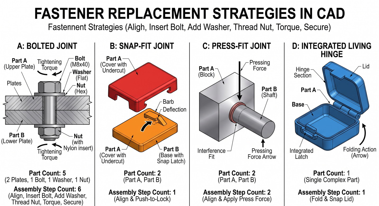
Design for assembly (DFA), usually paired with DFM under the combined acronym DFMA, asks a different question: not whether each part can be made, but whether the whole product can be put together efficiently and correctly. The two biggest levers are reducing part count and making incorrect assembly physically difficult.
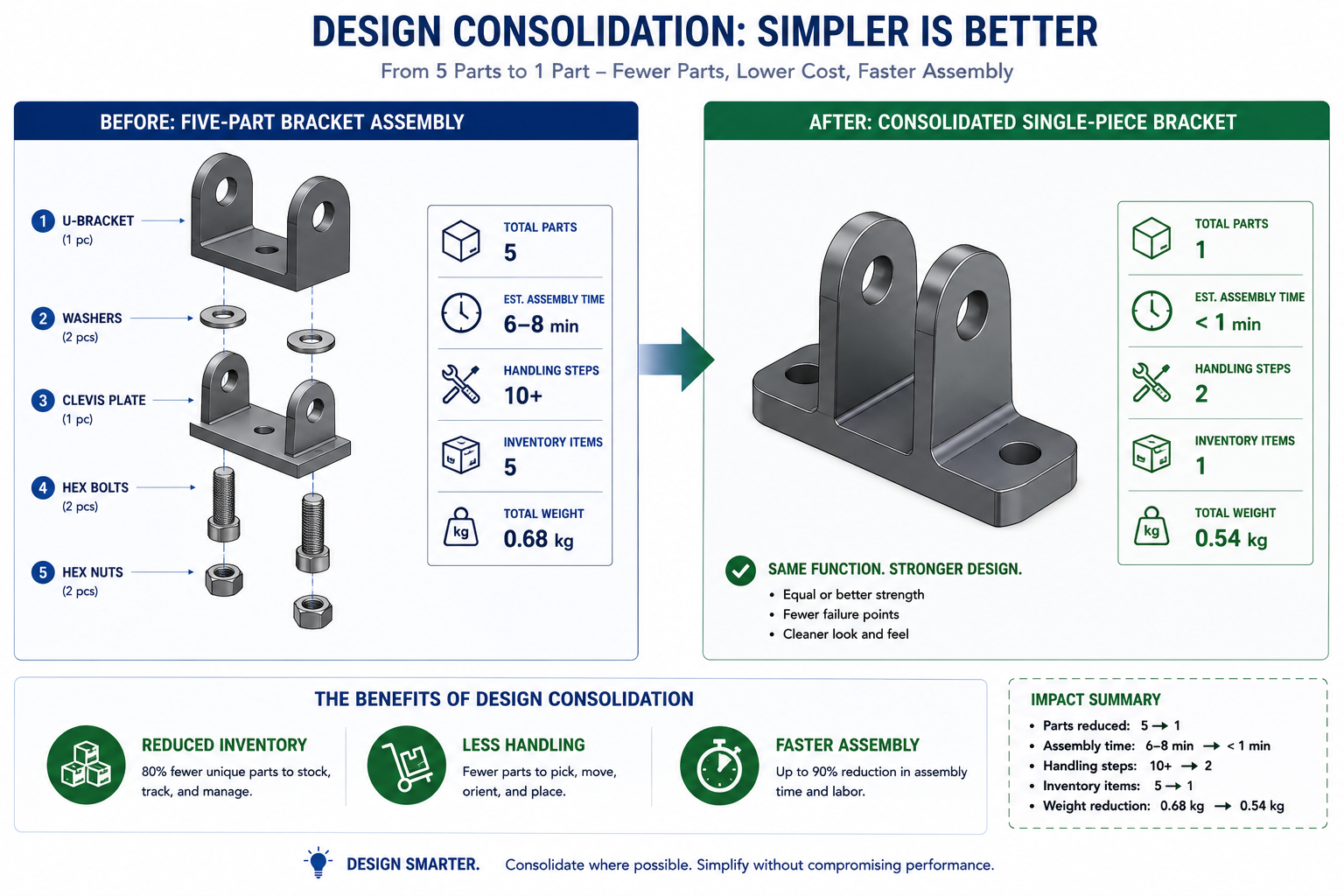
Every part in an assembly carries cost beyond its own material and machining: it needs to be ordered, stocked, picked, oriented, and joined, with paperwork and quality records to manage. A design that combines three separate brackets into one moulded or formed piece eliminates two entire chains of that overhead, not just the material cost of two fewer parts. This feature consolidation is one of the highest-leverage things a DFM review can catch, since savings compound across every unit ever built.
Poka-Yoke: Making the Wrong Assembly Physically Impossible
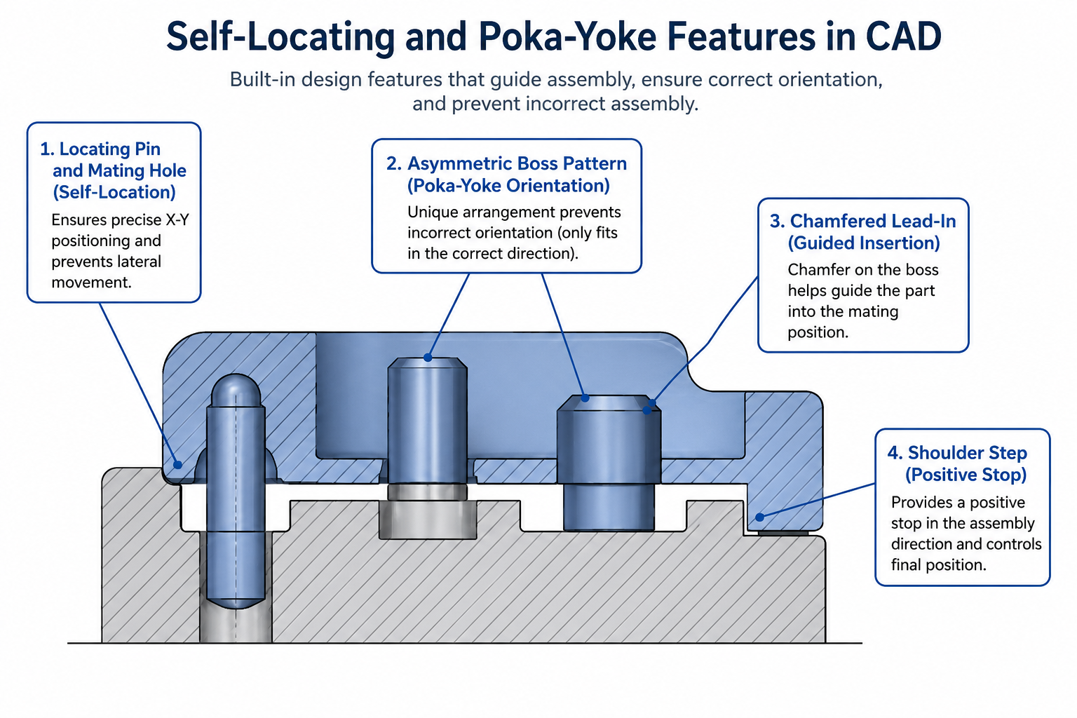
The Japanese term poka-yoke translates roughly to mistake-proofing: designing parts so incorrect assembly is either impossible or immediately obvious. A connector symmetric enough to plug in backwards eventually will get plugged in backwards on a production line, no matter how good the work instructions are. A keyed, asymmetric connector shape removes that failure mode entirely, at zero ongoing cost once the tooling exists.
The same thinking applies to brackets, covers, and any orientation-sensitive part. If a part looks identical in two orientations but only works correctly in one, build in an asymmetric feature, an offset hole or a notch, that makes the correct orientation the only one that fits. This is far cheaper to design in at the CAD stage than to manage through inspection or training later.
Mixed Materials and the Joining Problem
Combining dissimilar materials is sometimes unavoidable, but it needs to be a deliberate decision, not something that falls out of picking the cheapest material for each part independently. Two metals with very different positions on the galvanic series will corrode at the joint when moisture is present, even if neither corrodes on its own. Materials with very different coefficients of thermal expansion build up stress at a rigid joint as temperature cycles, eventually leading to fatigue cracking or loosened fasteners.
This doesn’t mean avoiding mixed materials. It means that whenever a design crosses a material boundary, that joint deserves a specific look: is there galvanic corrosion risk requiring an isolating coating or gasket, and is there a CTE mismatch requiring the joint to accommodate movement rather than resist it rigidly. Catching this at the design stage is far cheaper than diagnosing a field failure years after shipping.
Worked Examples
The enclosure with uneven walls: A consumer electronics housing, moulded as a single shell hollowed from a solid block model, ended up with wall thickness ranging from 1.2mm to 4.8mm because the hollowing offset the outer surface by a constant amount except where ribs and bosses interrupted it. The DFM review flagged the variation as well outside the 10-15 percent guideline, and flagged the abrupt step between the 4.8mm and 1.8mm sections with no taper.
The redesign replaced the thick corner with a 1.8mm wall plus a separate internal rib, tapered into the surrounding wall over roughly 6mm. The screw boss in that corner was rebuilt at 60 percent of nominal wall thickness with a gusset rib. The result eliminated sink mark risk entirely and cut part mass by roughly 12 percent, with no loss of stiffness, all caught in CAD before the tool was cut.
The bracket with an inaccessible pocket: A machined aluminum bracket had a straightforward rectangular pocket on its underside, positioned beneath an overhanging flange added for a separate mounting requirement. The DFM review found that no standard-length end mill could reach the pocket without colliding with the flange, leaving only a costly custom long-reach tool or a redesign.
Relocating the flange 8mm further from the pocket gave a standard tool clearance to approach directly, with no change to the flange’s mounting function since the new position still aligned with the mating bracket’s hole pattern. This avoided a roughly 70 percent per-part cost premium the shop had estimated for the custom tooling, and took an afternoon of CAD work instead of a multi-week delay.
Frequently Asked Questions
What is the difference between DFM and DFA? DFM focuses on whether an individual part can be produced efficiently by a given process, covering wall thickness, draft angle, and tolerances. DFA focuses on whether the parts can be assembled efficiently once they exist, covering part count reduction and mistake-proofing. The two are usually discussed together as DFMA because they overlap heavily in practice: a part that’s hard to make is often hard to assemble too.
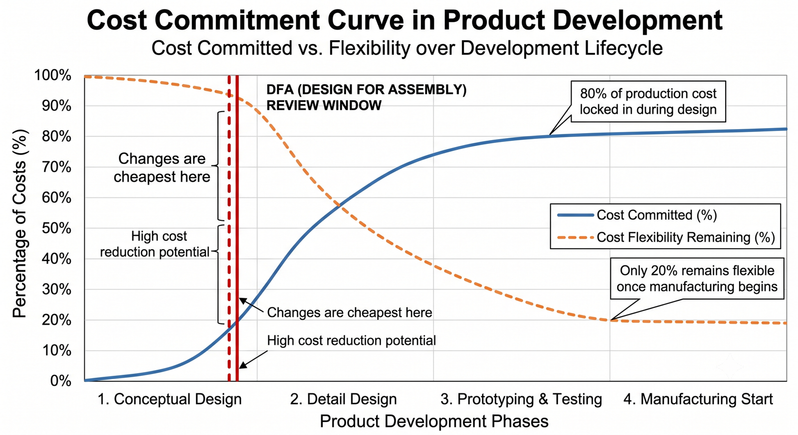
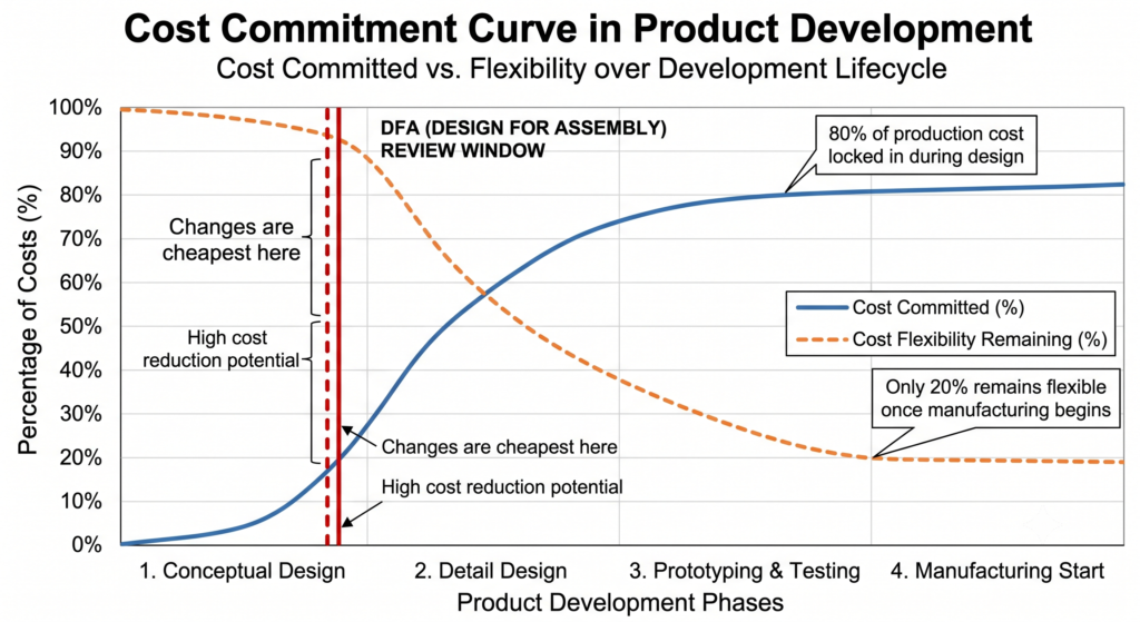
When in the design process should a DFM review happen? As early as possible, and more than once. The first pass belongs at the concept or early CAD stage, before significant effort goes into specific geometry, when changes are cheapest. A second pass belongs just before release for tooling or first-article quoting, the last point where a change avoids tooling cost entirely. Waiting until after a prototype reveals a problem pushes the fix to the most expensive stage possible.
How do I know what wall thickness or tolerance my supplier can actually achieve? Ask them directly for their process capability data rather than relying on generic published guidelines. The numbers in a checklist like this are reasonable starting points, but actual capability varies by shop, machine, tooling condition, and the specific material and geometry involved. The earlier you get this data, the fewer surprises at first-article inspection.
Why does tightening a tolerance cost so much more than the value suggests? Because tighter tolerances usually trigger a step change in process, not a smooth increase in effort. A hole within a few microns of nominal often can’t be held by drilling alone and needs reaming or boring. A flatness requirement tight enough for a sealing surface often needs a separate grinding operation. Each step change adds a separate operation, setup, and often inspection equipment, which is why tolerance cost looks like a series of jumps rather than a straight line.
Can a DFM checklist replace talking to a manufacturing engineer or supplier? No. A checklist catches the common, well-documented mistakes that show up across most projects in a given process, which prevents the most frequent and expensive surprises. It can’t replace the specific knowledge a manufacturing engineer or experienced supplier has about your particular part, material, and equipment. The most effective use is as preparation: work through it yourself first, then bring a tighter design to the conversation so it can focus on the genuinely difficult decisions.
What’s the single highest-impact DFM change most engineers could make? Reducing part count through feature consolidation, especially in assemblies that grew across multiple design iterations without anyone stepping back to ask whether several parts could become one. Every part carries cost beyond material and machining, ordering, stocking, handling, and quality tracking all scale with part count. Combining three brackets into one moulded piece often pays for the redesign effort many times over, since savings compound on every unit built.
Key Takeaways
Every item in this checklist describes a constraint that exists whether or not the design respects it. A wall too thick relative to its neighbours will sink. A tool without draft will not pull the part. A bend too tight for the material will crack. None of these are arbitrary rules; they’re physical realities that surface sooner or later. The only real choice an engineer has is whether they show up on a CAD screen during review, or on a production floor after tooling is already cut.
None of the numbers here are exotic: a 1 to 2 degree draft angle, a rib at 50 to 60 percent of wall thickness, a bend radius around one times material thickness, a tolerance no tighter than the function actually demands. What makes DFM valuable isn’t the difficulty of any single rule. It’s the discipline of checking every part against the rules that govern the process it will actually go through, before that process turns an overlooked detail into an expensive lesson.
Build the checklist into your design review process, keep the reference numbers close during CAD work, and treat your supplier’s actual process capability data as the final word over any general guideline, including this one.