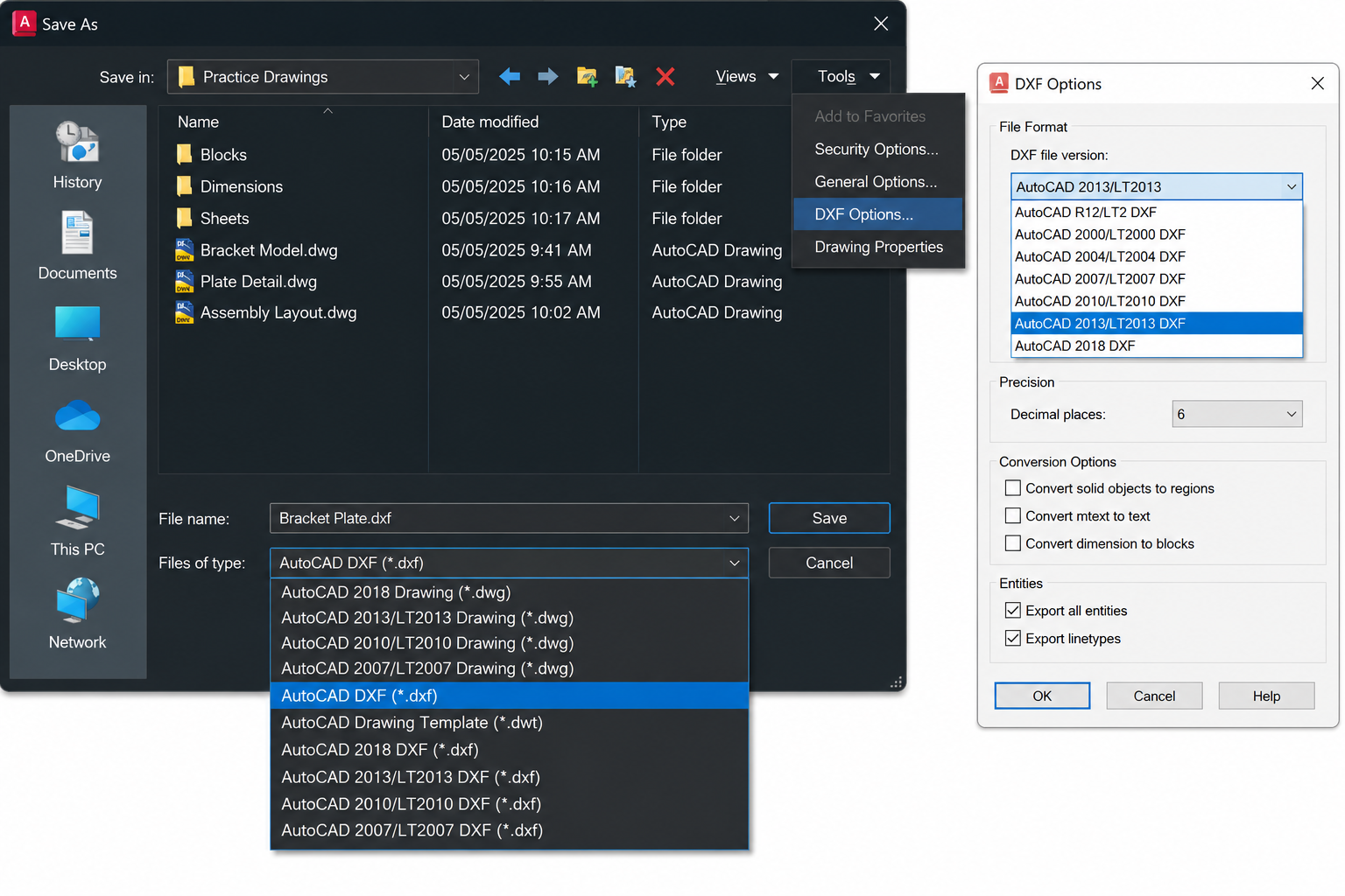
DXF files (Drawing Exchange Format) are the universal passport of the CAD world. Where the native DWG file format is AutoCAD’s proprietary drawing file, DXF is the open, interoperable format that allows AutoCAD drawings to be shared with virtually any other CAD software, CNC machine, laser cutter, vinyl cutter, or fabrication system in existence.
If you have ever needed to send a drawing to a laser cutting shop, share geometry with a client using different CAD software, import a survey from GIS software, or get an AutoCAD drawing into a 3D modelling tool like Rhino or SolidWorks, DXF is almost certainly the format that bridges that gap. Understanding how to open, import, export, and prepare DXF files correctly in AutoCAD is one of the most practically valuable skills in the professional CAD toolkit.
This guide covers everything: what DXF files actually are, the three different ways to bring them into AutoCAD (and why they are different), how to export DXF files at the correct version for your recipient, how to prepare a clean DXF for CNC and fabrication use, how to fix the most common DXF problems, and a complete comparison of DXF versus DWG to help you decide which format to use in any situation.
| Quick Answer: To open a DXF file in AutoCAD: go to File > Open, change the file type filter to DXF (*.dxf), navigate to the file, and click Open. AutoCAD opens the DXF as a new drawing. To import DXF into an existing drawing: type DXFIN in the command line (only works on a blank new drawing) or use INSERT > Attach to insert the DXF as a block reference. To export as DXF: go to File > Save As and select AutoCAD DXF (*.dxf) from the format dropdown. |
What Is a DXF File? Understanding the Format
DXF stands for Drawing Exchange Format (also sometimes called Drawing Interchange Format). It was developed by Autodesk in 1982, the same year AutoCAD was first released, specifically to allow AutoCAD drawings to be shared with and used by other software programs without requiring a licensed copy of AutoCAD.
At its core, a DXF file is a text-based (ASCII) or binary file that describes the contents of a CAD drawing in a structured, documented format. Unlike the proprietary DWG format (which is encoded and undocumented by Autodesk), the DXF format has a publicly documented specification, which means any software developer can write code to read and write DXF files correctly. This is why DXF has become the universal interchange standard across the entire CAD and fabrication industry.
What a DXF File Contains
A DXF file stores the same fundamental drawing data as a DWG file, but with some important limitations:
- Geometric entities: Lines, arcs, circles, polylines, splines, ellipses, and all standard 2D and 3D drawing objects.
- Layer structure: Layer names, colours, linetypes, and visibility states are preserved in DXF files.
- Blocks: Block definitions and insert references are stored, though complex dynamic blocks may be simplified or lost depending on the DXF version.
- Dimensions and annotations: Dimension objects and text are included, though font rendering may differ between applications.
- Hatching: Hatch patterns are stored, though complex pattern types may not transfer correctly to all DXF readers.
- NOT included in DXF: Complex parametric constraints, AutoCAD-specific object types (dynamic block properties, data links, point clouds), and some rendering and visualisation data are lost or simplified when saving to DXF.
| Historical Note: Autodesk introduced DXF in 1982 specifically because early AutoCAD users needed to share drawings with other software. As AutoCAD evolved, the DXF format evolved with it, with new versions (R12, R14, 2000, 2004, 2007, 2010, 2013, 2018) supporting increasingly complex features. However, older DXF versions remain widely used because many fabrication machines and older CAD systems cannot read newer DXF versions. Choosing the right DXF version for your recipient is one of the most important practical decisions in DXF workflow. |
Read The related Blog on AutoCAD Tutorial for Beginners and Professionals 2026
DXF vs DWG: When to Use Each Format
Understanding when to use DXF versus DWG is one of the most practical decisions in professional CAD work. The two formats serve different purposes, and choosing the wrong one causes unnecessary compatibility problems.
| Criterion | Use DWG | Use DXF |
| Working with other AutoCAD users | Yes — DWG is AutoCAD’s native format. Preserves all AutoCAD-specific features. | Not necessary — DXF adds no benefit when both parties use AutoCAD. |
| Sharing with users of other CAD software (SolidWorks, Rhino, Revit, Fusion 360) | Sometimes — many modern CAD tools read DWG. Check recipient first. | Yes — DXF has broader support across non-Autodesk tools and older software. |
| Sending to CNC machines, laser cutters, vinyl cutters, or waterjet machines | Rarely — most fabrication software and controllers prefer DXF. | Yes — DXF R14 or R2000 is the near-universal fabrication format. |
| Preserving all AutoCAD features (dynamic blocks, parametric constraints, xrefs) | Yes — DWG preserves all native features. DXF may lose or simplify them. | Not ideal — complex features are simplified or lost in DXF. |
| Sending to clients who only need to view geometry (not edit) | DWG or PDF are both suitable options. | DXF works but PDF is simpler for view-only distribution. |
| Importing into GIS, mapping, or survey software | Sometimes supported | Yes — DXF is widely supported by ArcGIS, QGIS, and survey software. |
| Archiving drawings for long-term storage | Yes — DWG with ETRANSMIT to bundle all dependent files. | Not ideal for archiving — DXF may lose some data versus DWG. |
| Compatibility with very old software (pre-2000) | DWG compatibility may be limited for very old versions. | Yes — DXF R12 is readable by virtually any CAD application ever made. |
| Rule of Thumb: Use DWG as your primary working format and for sharing with other AutoCAD users. Use DXF as your delivery format when the recipient uses non-Autodesk software, when sending to fabrication or CNC services, or when maximum compatibility with unknown software is required. Never use DXF as your internal working format — always keep a DWG master and export DXF from it as needed. |
Three Ways to Open or Import a DXF File in AutoCAD
There are three distinct methods for bringing a DXF file into AutoCAD, and they produce meaningfully different results. Choosing the right method depends on whether you want the DXF content to become your working drawing, to merge into an existing drawing, or to be referenced without permanently adding to the drawing database.
| Method | Command / Access | What It Does | Best For |
| Open as New Drawing | File > Open > change file type to DXF, or drag-and-drop DXF onto AutoCAD | Opens the DXF as a standalone new drawing. Full geometry, layers, and blocks are preserved and editable. | When the DXF IS the drawing you want to work on and edit directly |
| DXFIN Command | Type DXFIN in command line (must be used on a blank/new drawing only) | Imports the entire DXF file into the current drawing. Current drawing must be a new blank drawing — DXFIN fails if the drawing already contains objects. | When you need to import DXF content into a freshly created drawing before adding your own geometry |
| INSERT / ATTACH (as a block reference) | Type INSERT or ATTACH > browse to DXF file and change filter to *.dxf | Inserts the DXF content as a block reference at a specified insertion point, scale, and rotation. The DXF geometry is treated as a single block object. | When you need to reference DXF geometry in an existing drawing without merging it permanently — for example, importing a site plan or background reference |
Method 1: Opening a DXF File as a New Drawing — Step by Step
- Launch AutoCAD.
- Go to File > Open (or press Ctrl + O).
- In the Open dialogue, change the Files of type dropdown to DXF (*.dxf).
- Navigate to your DXF file and click it to select it.
- Click Open. AutoCAD opens the DXF as a new drawing. The title bar shows the DXF filename.
- Immediately after opening, type ZOOM and press Enter, then type E and Enter (Zoom Extents) to fit the imported geometry to the screen.
- Check units immediately (see the Units section below). A newly opened DXF may use different units from your AutoCAD default.
Method 2: DXFIN Command — Step by Step
- Open a new blank drawing in AutoCAD (File > New). This is essential — DXFIN will fail if the current drawing already has any objects.
- Type DXFIN and press Enter.
- In the file selection dialogue that opens, navigate to the DXF file and click Open.
- AutoCAD reads the DXF and populates the blank drawing with all geometry, layers, and blocks from the file.
- Type ZOOM > E to fit the imported geometry to screen.
Method 3: INSERT / ATTACH — Step by Step
- Open your existing drawing where you want to add the DXF reference.
- Type ATTACH and press Enter (or go to Insert tab > Reference panel > Attach).
- In the Select Reference File dialogue, change the file type filter to DXF (*.dxf) and browse to your file.
- Click Open. The Attach External Reference dialogue opens.
- Set the insertion point, scale, and rotation as needed. For a reference drawing in the same coordinate system, use 0,0,0 as the insertion point and 1 as the scale.
- Click OK. The DXF is inserted as a block reference in your drawing.
- To explode the block and make the DXF geometry fully editable within your drawing, select it and type X (EXPLODE), then Enter.
| DXFIN Limitation: The DXFIN command is the original AutoCAD method for importing DXF files, but it only works on completely blank new drawings. If you try to use DXFIN on a drawing that already has any objects, AutoCAD will display an error. In modern AutoCAD (2010 onwards), simply opening a DXF with File > Open is almost always the better approach — it is more reliable and has no blank-drawing restriction. |
How to Export a Drawing as a DXF File from AutoCAD
Exporting a DXF from AutoCAD is straightforward, but choosing the correct DXF version and preparing the drawing correctly before exporting makes the difference between a DXF that works first time and one that causes problems for the recipient.
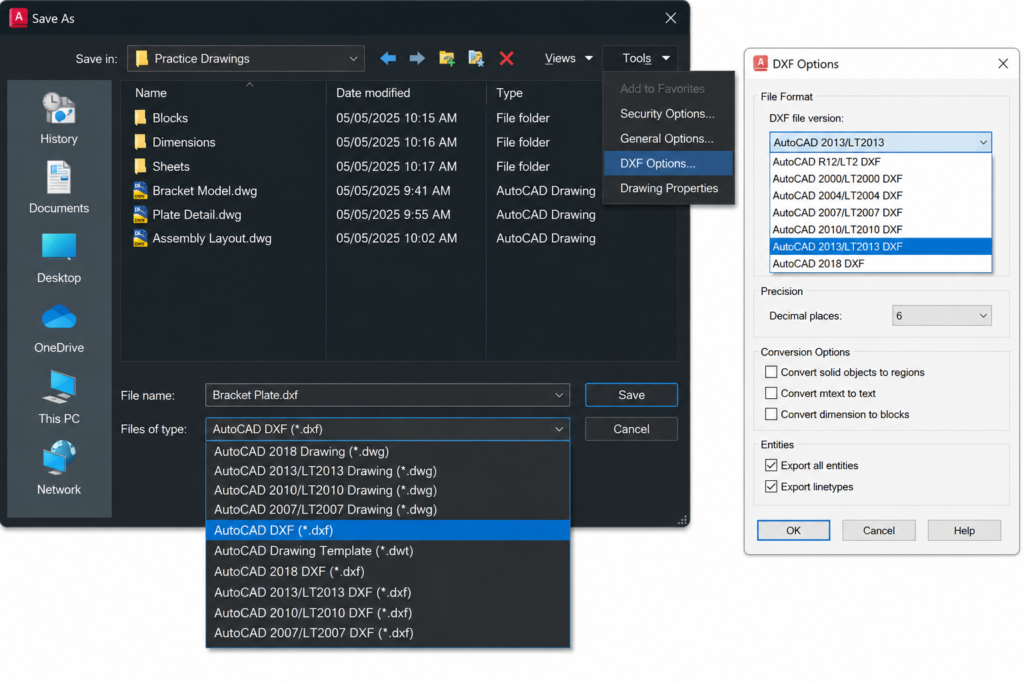
Method A: Save As DXF (Full Drawing Export)
- Ensure your drawing is in the state you want to export (correct layers visible, model space or paper space as appropriate).
- Go to File > Save As (or press Ctrl + Shift + S).
- In the Save As dialogue, change the Files of type dropdown from DWG to AutoCAD DXF (*.dxf).
- Click the Tools > Options button in the Save As dialogue (not the main AutoCAD Options) to access DXF format settings.
- Select the appropriate DXF version (see the version selection table below). The default is the current AutoCAD version — change it if the recipient needs an older format.
- Enter the filename and navigate to the save location.
- Click Save. The DXF file is created.
Method B: DXFOUT Command
- Type DXFOUT in the command line and press Enter.
- In the Save Drawing As dialogue, the file type is automatically set to DXF.
- Set the filename and click Save. The DXF is exported using the most recently used DXF version setting.
Method C: Export Selected Geometry Only
To export only specific geometry (not the entire drawing) as a DXF:
- Select the geometry you want to export.
- Type WBLOCK (Write Block) and press Enter.
- In the Write Block dialogue, select Objects and ensure the selected geometry is referenced.
- Set the File name and path and change the file type to DXF.
- Click OK. Only the selected geometry is exported to the DXF file.
Choosing the Right DXF Version When Exporting
This is the single most important and most commonly neglected aspect of DXF file export from AutoCAD. AutoCAD offers multiple DXF versions when saving, and choosing the wrong one causes geometry to be missing, simplified, or unreadable by the recipient’s software or machine.
| DXF Version | AutoCAD Release | Best Used For | Limitations |
| DXF R12 (AC1009) | AutoCAD Release 12 (1992) | Maximum compatibility: CNC controllers, older plotters, vintage CAD systems, any unknown recipient | No true arc support in some readers; no true ellipses; polylines only; blocks simplified; no true colours; no modern lineweights |
| DXF R14 (AC1014) | AutoCAD Release 14 (1997) | CNC machines, laser cutters, vinyl cutters, most fabrication software. The fabrication industry standard. | Limited true colour support; no plot styles; no sheet sets; dynamic blocks not supported |
| DXF 2000 / 2000i / 2002 (AC1015) | AutoCAD 2000/2002 | Sharing with slightly older CAD software; good balance of compatibility and feature support | Limited advanced annotation support; no parametric constraints |
| DXF 2004 / 2005 / 2006 (AC1018) | AutoCAD 2004-2006 | Sharing with CAD software from mid-2000s. Good general-purpose compatibility. | No dynamic blocks in full; no parametric; still limited 3D solid support |
| DXF 2007 / 2008 / 2009 (AC1021) | AutoCAD 2007-2009 | Sharing with modern CAD tools that support DXF 2007. Better 3D and spline support. | Not supported by older machines and controllers |
| DXF 2010 / 2011 / 2012 (AC1024) | AutoCAD 2010-2012 | Modern CAD software exchange, 3D model data, full spline and surface support | Many CNC and fabrication systems cannot read this version |
| DXF 2013-2018 (AC1027/AC1032) | AutoCAD 2013-present | Sharing with current AutoCAD versions and modern design software only | Limited compatibility; many systems cannot read it; not suitable for fabrication |
| Fabrication Industry Standard: When sending a DXF to a laser cutting service, CNC router, waterjet cutter, plasma cutter, or vinyl cutter, always use DXF R14 (AC1014). If R14 causes any issues (rare), try R12. These two versions are readable by virtually every fabrication machine and controller ever manufactured. Never send a 2010 or later DXF to a fabrication service without first confirming they can read it. |
Checking and Fixing Units After Importing a DXF
Unit mismatch is the most common problem after importing a DXF file, and it is one that goes unnoticed until dimensions are measured or the drawing is used for fabrication. A drawing that was created in millimetres but opens in AutoCAD set to inches will appear to be the correct shape but all dimensions will be wrong by a factor of 25.4.
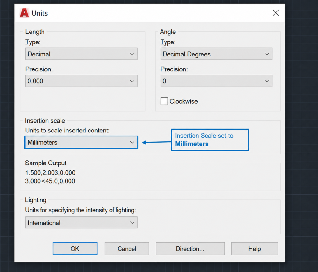
How to Check Units After Importing
- After opening or importing a DXF, type UNITS (or UN) and press Enter.
- The Drawing Units dialogue opens. Check the Length Type and Insertion Scale settings.
- If the units are incorrect, change the Insertion Scale to the correct unit (Millimeters or Inches as appropriate).
- Click OK.
- Draw a known dimension — a line you know should be, for example, 100mm long — and use DIST (Measure Distance) to verify it measures correctly.
Rescaling a Drawing That Was Imported at the Wrong Units
If a drawing was imported at the wrong scale (for example, a millimetre drawing that AutoCAD interpreted as inches), rescale the entire drawing:
- Type SCALE (or SC) and press Enter.
- Type ALL and press Enter to select all objects, then press Enter to confirm.
- Click any point as the base point (0,0 is safest).
- Enter the scale factor. For a millimetre drawing incorrectly shown in inches, the scale factor is 25.4 (to scale up from inches to mm). For an inches drawing shown in millimetres, use 0.03937 (1/25.4).
- Press Enter. All geometry is rescaled. Verify dimensions with DIST.
Layer Management When Working with DXF Files
Layer information is generally preserved in DXF files, but the way layers transfer depends on the DXF version, the sending software, and how the DXF was prepared. Understanding what to expect prevents layer confusion on import.
What Layer Information DXF Preserves
- Layer names: Preserved in all DXF versions.
- Layer colours (by colour index): Preserved. True colour (RGB) values preserved in DXF 2000 and later only.
- Linetype names: Layer linetype names are stored, but the actual linetype definition may need to be loaded manually if it is not a standard AutoCAD linetype.
- Layer on/off and frozen state: Preserved in most DXF versions.
- Layer lineweight: Preserved in DXF 2000 and later. May be lost in R14 and earlier.
Managing Layers After Import
After importing a DXF, open the Layer Properties Manager (LA) to review the imported layer structure. Common issues:
- Unexpected layer names: Some CAD applications use non-standard layer naming conventions. Rename layers using the Layer Properties Manager to match your drawing standards.
- Missing linetypes: If layers reference linetypes that are not loaded in the current drawing, objects may display with a continuous line. Use LINETYPE > Load to load the required linetypes from AutoCAD’s standard linetype library.
- All geometry on one layer: Some DXF exporters flatten all geometry to a single layer. If this happens, inspect the imported geometry and manually reassign objects to appropriate layers.
Preparing a Clean DXF for CNC, Laser Cutting, and Fabrication
Sending a raw AutoCAD DXF to a fabrication service without preparing it properly is one of the most common and costly mistakes in engineering and design work. Fabrication machines and their CAM software have specific requirements for DXF files that are very different from the requirements of a standard design drawing. A DXF that looks perfect in AutoCAD can produce cut paths with errors, skipped features, double cuts, or incorrect dimensions at the machine.
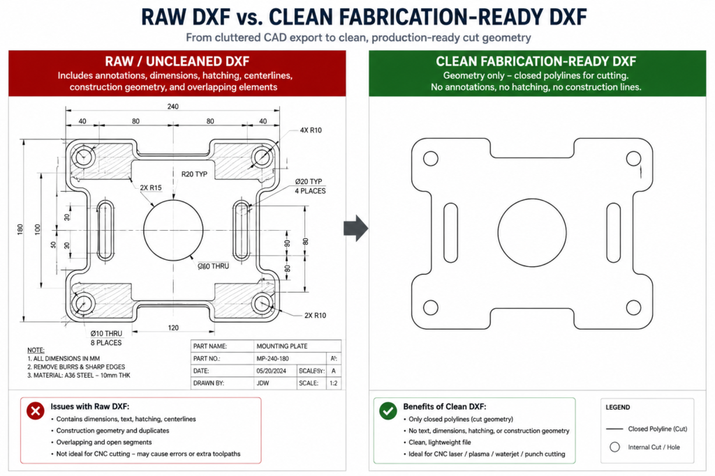
The following preparation workflow produces a clean, fabrication-ready DXF that meets the requirements of virtually any CNC, laser, waterjet, or vinyl cutting service.
Step 1: Work Only in Model Space for Fabrication DXFs
Fabrication machines read only the geometry in model space. Paper space layouts, viewports, and title blocks should not be included in a fabrication DXF. Ensure that your cut profiles are in model space at 1:1 scale before beginning the export preparation.
Step 2: Ensure All Profiles Are Closed Polylines
Most fabrication CAM software requires that cut profiles are closed polylines rather than individual line and arc segments. Use PEDIT > Join to combine all segments forming each cut profile into closed polylines. Use BOUNDARY to auto-detect and create closed polylines from complex boundary areas. Verify each profile by clicking it — if it highlights as one object, it is a single polyline.
Step 3: Remove Duplicate and Overlapping Lines
Overlapping geometry causes double-cut passes at the machine, wasting material and potentially damaging the workpiece or cutting tool. Run the OVERKILL command (type OVERKILL, Enter, select all, Enter) to automatically delete duplicate and overlapping geometry. After OVERKILL, zoom into complex areas to verify no accidental geometry was removed.
Step 4: Remove All Non-Geometry Content
Fabrication DXFs should contain cut geometry only. Remove or move to a separate non-plotted layer:
- Dimensions and annotations
- Title blocks and borders
- Centre lines and reference lines
- Hatch patterns
- Text labels
- Construction geometry
Step 5: Explode All Blocks
Most fabrication CAM software cannot process AutoCAD block references correctly. Type EXPLODE (X) and select all geometry, then Enter. This converts all blocks into their constituent geometry. Run OVERKILL again after exploding to remove any duplicate geometry created by the explosion.
Step 6: Purge the Drawing
Type PURGE (PU) and select purge all. This removes all unused layer definitions, block definitions, text styles, and dimension styles from the drawing, reducing file size and eliminating potential compatibility issues.
Step 7: Verify Units and Scale
Confirm that the drawing units are set correctly and that all geometry is at 1:1 real-world scale. Many laser cutting services work in millimetres. Type UNITS and verify that Insertion Scale is set to Millimeters (or the correct unit for the fabrication service). Measure a known dimension with DIST to confirm.
Step 8: Export as DXF R14
Save As DXF using DXF R14 (AC1014) format. This is the fabrication industry standard. If the service specifically requests R12, use that instead. Avoid any DXF version newer than R2000 unless the service explicitly confirms they can read it.
| Pro Tip for Laser Cutting: Many laser cutting services also require that profiles be organised by operation type (e.g. cut, engrave, score) into different layers with specified colours. For example: red layer for outer cuts, blue for inner cuts, green for engraving. Check the specific requirements of your fabrication service before preparing the DXF — most publish a DXF preparation guide on their website. |
Using DXF Files with Other CAD and Design Software
| Software | DXF Import Support | DXF Export Support | Best DXF Version to Use | Notes |
| SolidWorks | Yes — full 2D and 3D DXF | Yes — sheet metal flat patterns to DXF | DXF 2007 or DXF R14 for 2D | SolidWorks imports DXF well for sketch geometry. 3D DXF geometry imports as imported bodies. |
| Fusion 360 | Yes — 2D and 3D DXF | Yes — sketches and drawings to DXF | DXF 2007 or 2010 | Fusion 360 handles modern DXF versions well. For sketch import, use 2D DXF. |
| Rhino 3D | Excellent — full support | Yes — DXF export well-supported | DXF 2007 or 2010 | Rhino’s DXF translator is one of the most reliable available. Named UCS imports as CPlane. |
| Illustrator / Inkscape | Yes — 2D geometry only | Yes — vector paths to DXF | DXF R14 or 2000 | Only 2D geometry transfers. Text may need converting to curves/outlines before export. |
| Laser Cutting Software (LightBurn, etc.) | Yes — 2D geometry | Not applicable (machine software) | DXF R14 or R12 | Requires closed polylines. Remove all non-geometry content before sending. |
| CNC CAM Software (Mastercam, Fusion CAM) | Yes — 2D and 3D geometry | DXF export for documentation | DXF R14 for 2D profiles | Mastercam works best with clean closed polylines. Run OVERKILL before export. |
| QGIS / ArcGIS | Yes — geometry and layers | Yes — vector features to DXF | DXF R14 or 2000 | Layer names are used as feature attributes. Coordinate system must be set correctly. |
DXF File Troubleshooting: Common Problems and Fixes
| Problem | Most Likely Cause | Fix |
| DXF opens but drawing area appears blank (nothing visible) | Geometry exists but is very far from the origin, or drawing was saved with wrong units making objects too small or large to see at default zoom | Type ZOOM > E (Zoom Extents) immediately after opening to fit all geometry to screen. Then check units with UNITS command. |
| Geometry appears but dimensions are completely wrong (e.g. 100x too large or small) | Unit mismatch: DXF was created in millimetres but AutoCAD interpreted it as inches or vice versa | Use SCALE command to rescale all geometry by the correct factor (25.4 for mm to inch correction, 0.03937 for inch to mm). Then reset UNITS correctly. |
| Some geometry is missing after import | Missing geometry was on a layer that was turned off or frozen in the source drawing, or the geometry uses object types not supported by the DXF version | Type LA to open Layer Properties Manager and turn on all layers. Check if missing geometry is of a type not supported by the DXF version used. |
| Blocks appear as empty outlines or are missing after import | DXF was saved with an older version that simplified or excluded block definitions | Ask the sender to re-export using a newer DXF version (2000 or later), or ask them to EXPLODE all blocks before exporting |
| DXFIN fails with ‘Drawing not empty’ error | DXFIN requires a completely empty new drawing — the current drawing has objects in it | Open a new blank drawing first (File > New), then run DXFIN |
| DXF sent to fabricator causes double cuts or missed geometry | Duplicate/overlapping lines, open polylines, or non-geometry content (dimensions, text) included in the DXF | Run OVERKILL to remove duplicates. Use PEDIT Join to close open profiles. Remove all annotations and non-cut geometry. Re-export as DXF R14. |
| Linetypes appear as continuous (solid) lines after import | Linetype definitions from the DXF are not loaded in the current drawing | Type LINETYPE > Load, browse the AutoCAD linetype library (acad.lin or acadiso.lin), and load the required linetypes. Then REGEN to update display. |
| Hatching appears incorrectly or as solid fill after import | Hatch pattern type not supported by the DXF version, or hatch scale is incompatible with current units | Re-apply hatch in AutoCAD using the HATCH command on the imported boundary. Delete and recreate any hatch that transferred incorrectly. |
| DXF file cannot be opened at all (error on open) | DXF file is corrupted, or was generated by software with a non-standard DXF implementation | Open the DXF in a text editor to verify it is a valid ASCII file starting with ‘0SECTION’. If corrupted, ask sender to re-export. Try RECOVER command in AutoCAD. |
Batch Converting DWG Files to DXF
When you need to convert multiple DWG files to DXF format simultaneously, AutoCAD provides two approaches: the built-in Batch Plot utility and the DWG Trueview/Autodesk Batch Utility (a free tool from Autodesk).
Using the Autodesk Batch Conversion Utility
- Download and install Autodesk DWG TrueView (free from Autodesk) which includes a built-in batch conversion tool.
- Open DWG TrueView and go to Tools > Batch Convert.
- Add the DWG files you want to convert using the Add Files button.
- Set the output format to DXF and select the DXF version.
- Set the output folder and click Convert. All files are converted to DXF in the output folder.
Using AutoLISP for Batch DXF Export Within AutoCAD
For advanced users who need to batch convert files with specific settings from within AutoCAD, a simple AutoLISP script can be used to open each DWG and save it as DXF automatically. This approach allows full control over DXF version, layer filtering, and preparation steps as part of the conversion batch.
Frequently Asked Questions (FAQ)
How do I open a DXF file in AutoCAD?
To open a DXF file in AutoCAD, go to File > Open (or press Ctrl + O). In the Open dialogue, change the Files of type dropdown to DXF (*.dxf). Navigate to the DXF file and click Open. AutoCAD opens the DXF as a new drawing. After opening, type ZOOM > E (Zoom Extents) to fit the geometry to the screen, then check the drawing units with the UNITS command to confirm the correct measurement units are set.
How do I export a DXF file from AutoCAD?
To export a DXF file from AutoCAD, go to File > Save As. In the Save As dialogue, change the Files of type dropdown to AutoCAD DXF (*.dxf). Click Tools > Options in the dialogue to select the DXF version (use DXF R14 for fabrication, DXF 2007 for modern CAD software exchange). Enter the filename and click Save. Alternatively, type DXFOUT in the command line and press Enter.
What is the difference between DXF and DWG in AutoCAD?
DWG is AutoCAD’s proprietary native file format that stores all AutoCAD-specific features including dynamic blocks, parametric constraints, and xrefs. DXF (Drawing Exchange Format) is an open, documented format designed for maximum compatibility with other CAD software, CNC machines, and fabrication systems. Use DWG as your working format and for sharing with other AutoCAD users. Use DXF when sharing with non-AutoCAD software, CNC and laser cutting services, or any recipient where compatibility with their system is uncertain.
What DXF version should I use for CNC and laser cutting?
For CNC machines, laser cutters, waterjet cutters, and most fabrication services, use DXF R14 (also known as AC1014). This version is readable by virtually every fabrication machine and controller ever manufactured. If R14 causes issues, try DXF R12 for maximum compatibility. Avoid DXF versions newer than 2000/2002 for fabrication — many machines cannot read them.
Why does my DXF file look wrong after importing into AutoCAD?
The most common reasons a DXF looks wrong after import are: (1) Blank screen — type ZOOM > E to fit geometry to screen. (2) Geometry at wrong scale — unit mismatch between sender and AutoCAD. Type UNITS to check and SCALE to correct by factor 25.4 (mm to inch) or 0.03937 (inch to mm). (3) Missing geometry — open the Layer Properties Manager (LA) and turn on all layers. (4) Blocks appearing empty — ask the sender to re-export with a newer DXF version or explode blocks before export.
How do I import a DXF into an existing AutoCAD drawing?
To import a DXF into an existing drawing, use the INSERT or ATTACH command rather than DXFIN (DXFIN only works on blank new drawings). Type ATTACH, change the file filter to DXF, browse to the file, and click Open. Set the insertion point, scale, and rotation. After inserting, if you want the DXF geometry to be fully editable (not a block), select the inserted reference and type X (EXPLODE) to break it into individual objects.
How do I prepare a DXF for laser cutting from AutoCAD?
To prepare a clean DXF for laser cutting from AutoCAD: (1) Work in model space at 1:1 scale. (2) Use PEDIT > Join to ensure all cut profiles are closed polylines. (3) Run OVERKILL to remove duplicate lines. (4) Delete or move all non-geometry content (dimensions, text, hatches, title blocks) to a No Plot layer or delete them. (5) EXPLODE all blocks. (6) Run PURGE (PU) to clean unused definitions. (7) Verify units with UNITS command. (8) Save As DXF R14. Organise geometry into colour-coded layers if the cutting service requires it (check their DXF preparation guide).
What is the DXFIN command in AutoCAD?
DXFIN is an AutoCAD command that imports a DXF file into the current drawing. It can only be used on a completely new blank drawing — if the current drawing contains any objects, DXFIN will fail with an error. In modern AutoCAD (2010 onwards), simply opening a DXF with File > Open is almost always preferable to DXFIN, as it has no blank-drawing restriction and is more reliable with complex DXF files.
Conclusion
DXF files are the universal currency of CAD interoperability. Mastering how to import, export, clean, and troubleshoot them in AutoCAD opens up seamless communication with virtually every other CAD platform, fabrication service, and manufacturing system in the industry.
The most important lessons from this guide are: always verify units after importing a DXF; always choose the right DXF version when exporting (R14 for fabrication, 2007 for modern CAD software); always prepare a clean, geometry-only file before sending to a fabricator; and always keep your DWG master file as the source of truth, using DXF only as a delivery format.
The troubleshooting table in this article covers every common DXF failure mode. Most problems trace back to unit mismatches, overlapping geometry, or an incorrect DXF version choice — and all three are easily fixed once you know what to look for.
Return to the full guide: AutoCAD Tutorials for Beginners and Professionals. Continue with: How to Sort Tables in AutoCAD or Dynamic Block Lookup Tables Explained.