A set of engineering blueprint drawings lands on your desk. You need to review them, approve them, or pass them to a fabricator. But the sheets are covered in symbols, numbers, dashed lines, and abbreviations that make no immediate sense. You are not alone, and this is not as complicated as it looks.
Learning how to read engineering blueprints is a practical skill anyone can develop. You do not need an engineering degree to understand what a drawing is communicating. You need a clear framework for where to look and what each element means. This guide walks you through that framework in plain language, step by step.
What is Engineering Blueprint?
An engineering blueprint drawing is a technical document that communicates the exact geometry, dimensions, materials, tolerances and manufacturing requirements of a part or assembly. The name comes from the blue-tinted prints used in the 19th and 20th centuries. Today it refers to any formal technical drawing, whether printed or digital.
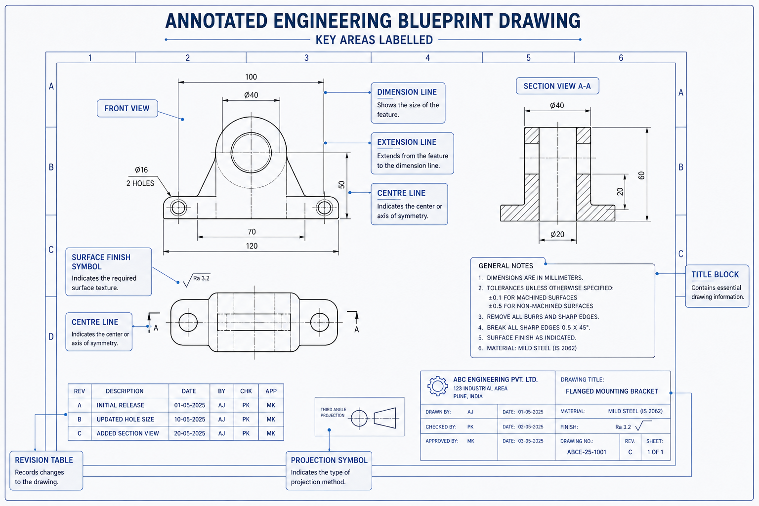
Step 1: Always Start with the Title Block
Before you look at a single line of geometry, go to the title block. It sits in the bottom-right corner of every engineering blueprint drawing, in every industry, on every sheet. It is the drawing’s identity card. Everything else you read on the sheet depends on confirming this information first.
| Title Block Field | What It Contains | Why Check It First |
| Drawing Title | The name of the part, assembly or system being drawn | Confirms you have the right drawing for your project |
| Drawing Number | A unique identifier in the document control system | Use this in all correspondence and purchase orders |
| Revision Level | A letter or number such as Rev A, Rev B, or Rev 3 | Outdated revisions cause manufacturing errors |
| Scale | The ratio between drawing size and actual part size | Tells you whether dimensions can be read visually |
| Units | Millimetres, inches, or other unit system | Mixing metric and imperial is a costly mistake |
| Date | When the drawing was created or last revised | Cross-reference with your project timeline |
| Drawn By / Approved By | Names and signatures of drafter and approving engineer | Confirms the drawing went through a review process |
| Company / Client | Organisation that produced or commissioned the drawing | Confirms which standards and formats apply |
Watch out: The single most common and costly mistake when working with engineering drawings is using an outdated revision. Before reviewing any drawing in detail, confirm the revision level matches your project’s current issued document register. A drawing that looks fine might be three revisions behind the current design.
Also in the Title Block: The Projection Symbol
Look for a small symbol near the title block that shows a truncated cone viewed from two angles. This tells you which projection standard the mechanical engineering blueprint uses.
- Third-angle projection (circle on the left, cone tip pointing right): Used in the United States, Canada, and Australia. Each view is placed on the same side as the direction you are looking from.
- First-angle projection (circle on the right, cone tip pointing left): Used in Europe, Asia, and most of the rest of the world. Each view is placed on the opposite side to the direction you are looking from.
Important: If you read a first-angle drawing as if it were third-angle (or vice versa), the views appear mirrored. This leads to parts being built with holes, features, and interfaces in the wrong positions. Always check the projection symbol before reading the views.
Step 2: Understand How the Views Work
Engineering drawings show a 3D object as a series of flat 2D views, like photographs of the part from different directions. The standard set is a front view, a top view, and a side view. Together, these three views define the complete shape of the part.
Think of it this way. If you placed a part inside a glass box and drew what you could see through each face, then unfolded the box flat onto paper, you would have an orthographic drawing. Each face of the box becomes one view on the sheet.
| View Name | What It Shows | Position on Sheet |
| Front View | The most descriptive face of the part, chosen to show the most geometry | Centre-left of the drawing sheet |
| Top View | Looking directly down onto the part | Directly above the front view |
| Right Side View | Looking at the right side of the part | To the right of the front view (third-angle) |
| Section View | A cut-open view showing internal geometry that would be hidden | Anywhere on sheet, labelled e.g. Section A-A |
| Detail View | An enlarged view of a small or complex area at a larger scale | Anywhere on sheet, labelled e.g. Detail B |
| Isometric View | A 3D-like pictorial view showing length, width and depth, for reference | Usually top-right corner, marked NOT TO SCALE |
Tip: When you first open a drawing sheet, identify all the views before you read any dimensions. Trace how each view relates to the others. The front view drives the layout and the other views align to it. Understanding this spatial relationship is the foundation for reading the rest of the drawing correctly.
Step 3: Decode the Lines and Dimensions
Not all lines on a mechanical engineering blueprint are the same. Each line type has a specific meaning, and misreading them is one of the most common errors for people new to technical drawings.
| Line Type | Appearance | What It Means |
| Visible (object) line | Solid, thick continuous line | A real edge visible in this view. The actual boundary of the part. |
| Hidden line | Medium-weight dashed line | A real edge that exists but is hidden behind another feature in this view. |
| Centre line | Thin alternating long-short dash | The axis or centre of a circular feature such as a hole or bore. Not a physical edge. |
| Dimension line | Thin line with arrowheads at each end | Indicates the distance being measured. The value sits above or within the line. |
| Extension line | Thin line from part edge | Connects the part geometry to the dimension line and shows what is being measured. |
| Section/cutting plane | Thick dash-dot line with arrows | Shows where an imaginary cut is made for a section view. Arrows show viewing direction. |
| Phantom line | Thin long-short-short dash | Shows adjacent parts, alternate positions or motion paths. Not part of the actual component. |
| Break line | Thin wavy or zigzag line | Indicates a portion of the part has been omitted from the drawing to save space. |
Reading Dimensions
Dimensions tell the manufacturer the exact size of every feature. Here are the main types you will encounter on any engineering blueprint drawing:
- Linear dimensions: Straight-line measurements between two points, shown with a dimension line and a value. The most common type.
- Angular dimensions: Measurements of angles between two surfaces or lines, shown in degrees.
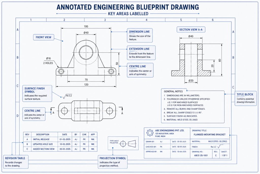
- Diameter dimensions: Shown with the diameter symbol (a circle with a diagonal line through it) before the number. Always applies to circular features.
- Radius dimensions: Shown with R before the number. Applies to arcs, fillets and rounded corners. Measured from centre to edge.
- Depth dimensions: Shown with a downward arrow symbol. Common on hole callouts to specify how deep the hole goes.
Tolerances on Dimensions
Dimensions carry tolerances, which are the allowable variation from the stated value. You will see these in three main forms:
- Plus/minus values: For example, 25.00 plus or minus 0.10 means the finished dimension can be anywhere from 24.90 to 25.10.
- Limit dimensions: The upper and lower limits are stated directly, such as 25.10 / 24.90.
- GD&T controls: Feature control frames that define geometric variation in addition to or instead of size tolerances.
Important: Never measure directly off a printed engineering blueprint drawing to determine dimensions. Drawings are not printed at a guaranteed 1:1 scale and even minor printing variation makes direct measurement unreliable. Always read the dimension value written on the drawing.
Step 4: Read the Engineering Blueprint Symbols, Notes, and Callouts
Beyond dimensions and views, engineering blueprint symbols communicate requirements that would take several lines of text to describe in words. Knowing the most common ones means you can scan a drawing and understand what is being asked of the manufacturer without needing to ask an engineer to translate every callout.
| Symbol / Notation | Looks Like | What It Means |
| Surface finish | Tick mark with a number (Ra value) | How smooth a surface must be. Ra 1.6 is smoother than Ra 6.3. Applies to mating and sealing surfaces. |
| Diameter | Circle with diagonal line before number | The feature is circular. This is the full width through the centre, not the radius. |
| Radius | R before a number | Half the diameter. Used for arcs, rounded corners and fillets. |
| Counterbore | Stepped circle symbol | A larger flat-bottomed hole above the main hole. Used to recess bolt heads flush with the surface. |
| Countersink | Angled V symbol | A conical recess at the top of a hole for a flush countersunk screw head. |
| Thread callout | e.g. M12 x 1.75 or 1/2-13 UNC | Specifies the thread size, pitch and type for holes or external threads such as bolts and studs. |
| TYP (Typical) | Written after a dimension value | This dimension applies to all identical features unless otherwise noted, not just the one it points to. |
| REF (Reference) | Written in brackets: (50) or 50 REF | For reference information only. Not to be used for inspection or manufacturing. |
| NTS (Not to Scale) | Written below a dimension or view | This view or dimension is not drawn proportionally. Read the written number, do not measure visually. |
The General Notes Section
Look for a notes section on the drawing, usually in the upper-left corner or near the title block. General notes apply to the entire drawing and cover things that cannot be expressed graphically: default tolerances for features without individual dimensions, surface treatment requirements, material standards, heat treatment specs, inspection requirements, and applicable regulatory or industry standards.
| A critical rule: When a general note conflicts with a specific dimension or symbol shown on the drawing, the specific instruction takes precedence. The general note applies only where nothing more specific has been stated. |
Engineering Blueprint Examples: What You Actually See and What It Means
Reading engineering blueprints is much easier when you have seen real examples of common callouts and know exactly what action to take. The table below covers the situations you are most likely to encounter when reviewing a mechanical engineering blueprint as a non-engineer.
Think of this as a translation guide. Left column is what the drawing shows. Middle column is what it actually means. Right column is what you should do as the reviewer.
| What You See on the Drawing | What It Means | What You Should Do |
| 50 +0.0 / -0.2 next to a circle | A hole with diameter 50mm, but it can be 49.8mm minimum. The plus side has zero tolerance. | This is a precision hole. Flag to the engineer if the tolerance seems tighter than usual for the application. |
| M8 x 1.25 inside a circle with arrow | An M8 metric threaded hole with 1.25mm thread pitch | Confirm the correct bolt or stud is specified in the BOM. Thread size must match the fastener. |
| Dashed rectangle inside a solid outline | A hidden internal pocket or cavity not visible in this view | Do not assume the part is solid. Check the section view to understand the internal geometry. |
| Section A-A with a line and arrows | A cut has been made along this line. Section view A-A shows what is inside. | Find the section view labelled A-A on the sheet or on the referenced sheet. |
| Ra 1.6 on a surface edge | That surface must be machined smooth to 1.6 microns average roughness | Smoother surfaces cost more to machine. Verify this is genuinely required for the application. |
| (75) in brackets near a dimension | This is a reference dimension only. Not used for inspection. | Do not use this number for manufacturing or checking. It is informational only. |
| REV C in the title block | This is the third revision of the drawing | Check your document register. Confirm Rev C is the currently issued version before proceeding. |
Real-World Example: Reviewing a Structural Steel Fabrication Package
You are a project manager reviewing a structural steel fabrication drawing package before issuing it to a fabricator for pricing. You are not a structural engineer, but you need to confirm the package is complete and ready to issue.
Here is exactly what you do:
- Confirm every sheet carries the same revision level. A mixed-revision package is a fabrication risk. If sheet 1 says Rev C and sheet 3 says Rev B, stop. Do not issue until the engineer confirms which sheets are current.
- Confirm the title block on each sheet references the correct project number and part descriptions. Mislabelled sheets cause real problems at a fabrication shop.
- Scan for revision clouds. These are the cloud-shaped borders around changed areas. If a revision cloud exists, check the revision table to confirm the change has been documented and signed off.
- Check for any RFI notations or open queries. An RFI marker means a question has been raised that has not been answered. Do not issue to fabrication with open RFIs.
- Confirm units are consistent across all sheets. If the drawing set uses millimetres throughout, every sheet should say mm. A single sheet using inches in a metric package causes manufacturing errors.
You do not need to verify every dimension or tolerance callout. That is the engineer’s role. Your job is to confirm the package is administratively complete, internally consistent, and shows no outstanding issues before it leaves your hands.
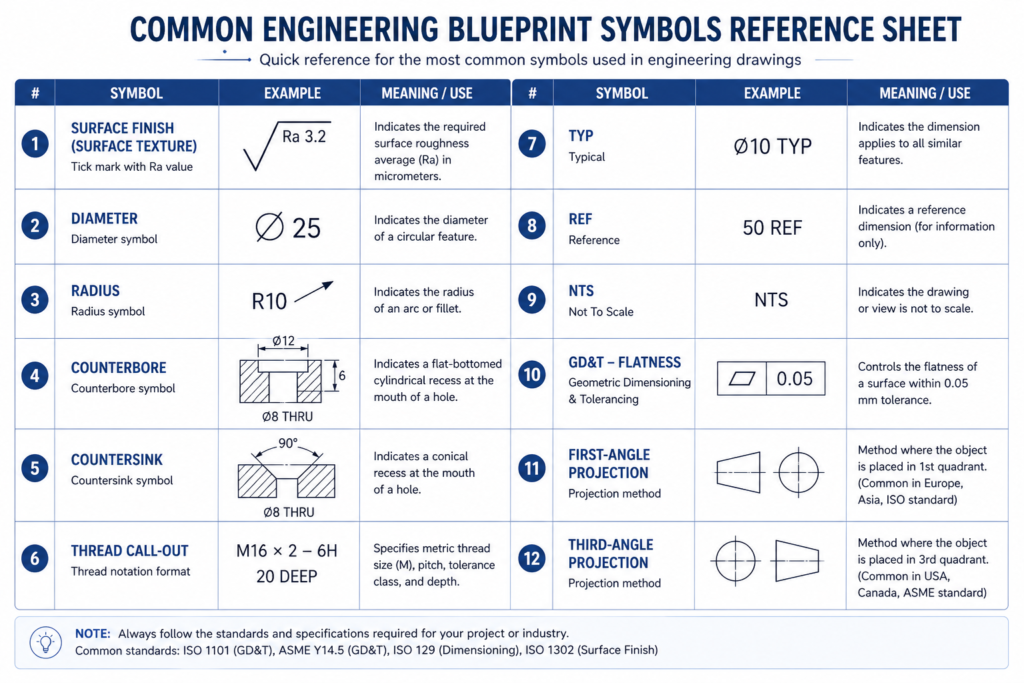
The Non-Engineer Blueprint Review Checklist
Use this checklist every time a drawing set arrives for review, approval, or issue to a supplier. You do not need engineering expertise to complete it. These ten checks catch the administrative and structural problems that cause the most expensive mistakes downstream.
| What to Check | Why It Matters |
| ☐ Confirm the revision level matches your project document register | Outdated drawings cause manufactured parts that do not match current design intent |
| ☐ Verify the drawing number and title match the expected part or assembly | Mislabelled drawings get issued to the wrong supplier or used for the wrong job |
| ☐ Check that units are stated and consistent across all sheets | Metric/imperial confusion is one of the most costly errors in manufacturing |
| ☐ Identify the projection method (first-angle or third-angle) | Misreading the projection direction produces mirrored or inverted parts |
| ☐ Confirm all views are present and labelled with section references matching | Missing or misreferenced views leave geometry undefined or ambiguous |
| ☐ Scan for revision clouds. Have all flagged changes been resolved? | Unresolved revision clouds indicate the design is not yet finalised |
| ☐ Check for any RFI notations or open queries on the drawing | Open RFIs mean unresolved questions. Do not issue to fabrication. |
| ☐ Confirm the general notes section is present and legible | Missing notes leave default tolerances, surface treatments and material specs undefined |
| ☐ Verify the drawing has been signed or approved in the title block | Unapproved drawings have not been through a design review. Issuing them is a risk. |
| ☐ Check the scale is stated and marked NTS where applicable | Unstated or incorrect scale creates confusion about whether dimensions can be read visually |
External Resource: For the international standard that governs engineering drawing practice, see ISO 128 (Technical Drawings: General Principles of Presentation) published by the International Organization for Standardization at iso.org. This is the foundational standard that defines line types, projection methods, and drawing conventions referenced in this guide.
The Bottom Line
Reading engineering blueprints does not require an engineering degree. It requires knowing where to look, what each element means, and what questions to ask when something is missing or unclear.
The title block tells you what you are looking at and whether it is current. The projection symbol tells you how to read the views. The line types tell you what is real geometry and what is reference information. The engineering blueprint symbols and dimension callouts tell the manufacturer exactly what to build. The general notes fill in the requirements that cannot be shown graphically.
Together, these elements give you enough information to review a mechanical engineering blueprint confidently, catch the issues that matter, and communicate clearly with the engineers and fabricators involved. The checklist in this guide covers the ten checks that catch the majority of drawing-related problems before they reach the shop floor. Use it every time a drawing set crosses your desk.
Know where to look. Read what it says. Ask when something is missing.
| Working With Engineering Drawings and Need Support? Whether you need a new drawing set produced, an existing one reviewed and updated, or a legacy drawing converted to current CAD standards, SimuTecra’s team handles the full range of engineering drafting work. Every drawing we produce is structured to be read correctly the first time. Send us your project details and we will come back with a clear scope and timeline. Reach out to us today, Simutecra |
Frequently Asked Questions
What is an engineering blueprint?
An engineering blueprint is a technical drawing that communicates the exact dimensions, materials, tolerances and features of a part or assembly to a manufacturer. Today the term covers both traditional blue-line prints and modern CAD-produced engineering drawing blueprints. The purpose is the same: give the maker everything needed to build the part correctly the first time.
What is the difference between first-angle and third-angle projection?
Both methods show the same three views of a part but arrange them differently on the sheet. In third-angle projection (used in the US, Canada and Australia), each view is placed on the side you are looking from. In first-angle projection (used in Europe and Asia), each view is placed on the opposite side. A small projection symbol in the title block tells you which method is used. Reading one as the other produces mirrored parts.
What does NTS mean on an engineering drawing?
NTS stands for Not to Scale. It means the feature or view is not drawn at a reliable proportion. When you see NTS, always use the written dimension value and never try to measure the feature visually off the sheet.
How do I know which dimension takes priority if values conflict?
Specific dimensions shown directly on the drawing geometry always override general notes. If two dimensions appear to conflict with each other, that is a drawing error. Raise it as an RFI (Request for Information) and do not send the drawing to fabrication until the discrepancy is resolved in writing.
What is a revision cloud on an engineering drawing?
A revision cloud is a curved, cloud-shaped border drawn around an area that changed from the previous revision. It is a visual flag so reviewers can quickly spot what is new. The change is also recorded in the revision table with the revision letter, a brief description and the date.
Do I need to understand GD&T symbols to review an engineering blueprint drawing?
For an administrative review covering revision level, completeness and approval status, no. For a more thorough technical review, a basic understanding of GD&T helps you confirm that critical tolerances are properly specified. Our separate guide on GD&T covers the symbols in detail if you need to go further.