Tag: engineering

  • Latest Advances in Mechanical Engineering (2026)

    Latest Advances in Mechanical Engineering (2026)

    Mechanical engineering has always been a discipline in motion, but the pace of change in 2026 is unlike anything the profession has experienced in living memory. In less than a decade, the field has absorbed artificial intelligence, quantum sensing, advanced soft robotics, 4D-printed metamaterials, hydrogen propulsion systems, and real-time digital twins, each transformative individually, and together reshaping what it means to be a mechanical engineer.

    This is not a list of futuristic concepts. These are technologies being deployed in factories, hospitals, laboratories, and energy systems right now. Mechanical engineers who understand them are commanding salary premiums of 15 to 25 percent above industry averages. Companies that have adopted them are reducing development timelines by 30 to 40 percent and cutting production costs significantly. The advances covered in this guide are not optional knowledge for the modern engineering professional. They are the new baseline.

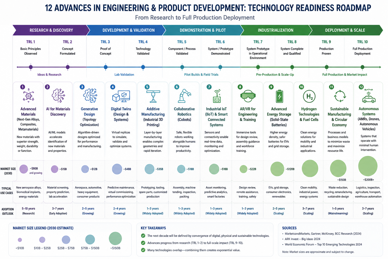
    This article covers the 12 most significant latest advances in mechanical engineering as of 2026: what each one is, why it matters, the data behind its adoption, the industries it is transforming, and what it means for engineers building careers today. Every section includes market data, real-world application examples, and direct career implications, content that no competing article provides.

    Infographic showing 12 latest advances in mechanical engineering ranked by technology readiness level from research to industrial deployment with market size data
    Key Statistic:  The U.S. Bureau of Labor Statistics reports the median annual wage for mechanical engineers reached $102,320 in May 2024, more than double the national median for all occupations. Employment is projected to grow 11 percent from 2023 to 2033, described as ‘much faster than average’, generating approximately 19,800 new job openings annually. Specialisations in AI-integrated roles, renewable energy, and robotics are commanding premiums of 15 to 25 percent above manufacturing averages.

    Why 2026 Is a Pivotal Year for Mechanical Engineering

    Mechanical engineering has always evolved, but typically in cycles measured in decades. A new manufacturing process here, a new simulation method there. What is different now is the simultaneous convergence of multiple transformative technologies, each mature enough to deploy at industrial scale, each reinforcing and enabling the others.

    Artificial intelligence is accelerating the design phase. Metal 3D printing is enabling geometries that were previously impossible. Digital twins are closing the loop between virtual design and physical reality. Advanced materials are overturning decades-old assumptions about what is strong, light, and thermally stable. Robotics is no longer confined to cage-enclosed factory automation. Hydrogen and electrification are reshaping propulsion engineering from its foundations.

    The engineers who will thrive in this environment are not those who understand one of these shifts in isolation. They are those who understand how they connect, how mastery of AI-assisted generative design changes what additive manufacturing can achieve, how digital twins enable predictive maintenance, how soft robotics and metamaterials are creating new categories of mechanical devices that did not exist five years ago. This guide provides that connected view.

    Technology AreaMarket Size 2024/2026Projected GrowthPrimary Engineering Impact
    Factory Automation$227 billion (2026)$461 billion by 2031 (ASME)Cobots, adaptive manufacturing, AI-controlled production lines
    Additive Manufacturing (global)$21 billion (2024)$73 billion by 2031 (MarketsandMarkets)Metal AM for production parts; medical implants; aerospace structures
    Digital Twins Market$17 billion (2024)$110 billion by 2032 (Grand View Research)Real-time monitoring; predictive maintenance; virtual testing
    Industrial Robotics$48 billion (2024)$100+ billion by 2030 (IFR)Cobots, autonomous mobile robots, surgical robots
    Hydrogen Economy$260 billion (2023 investment)Projected $1+ trillion/year by 2050 (IEA)Fuel cell systems, hydrogen turbines, storage vessel design
    Nanomaterials Market$12.42 billion (2023)15% CAGR through 2030Lightweight composites, MEMS, energy storage, biomedical implants
    Soft Robotics Market$2.5 billion (2024)$10.7 billion by 2030 (Grand View Research)Medical devices, food handling, wearables, search-and-rescue

    Advance 1: AI-Driven Design and Generative Engineering

    Artificial intelligence has entered the mechanical engineering design process at multiple levels simultaneously, and its impact is already measurable. AI-driven design tools and generative design software are not replacing engineers. They are dramatically expanding the design space any engineer can explore in a given time.

    Comparison of AI generative design component versus traditional machined component showing weight reduction and geometric complexity in mechanical engineering

    Generative Design: Exploring Thousands of Solutions Simultaneously

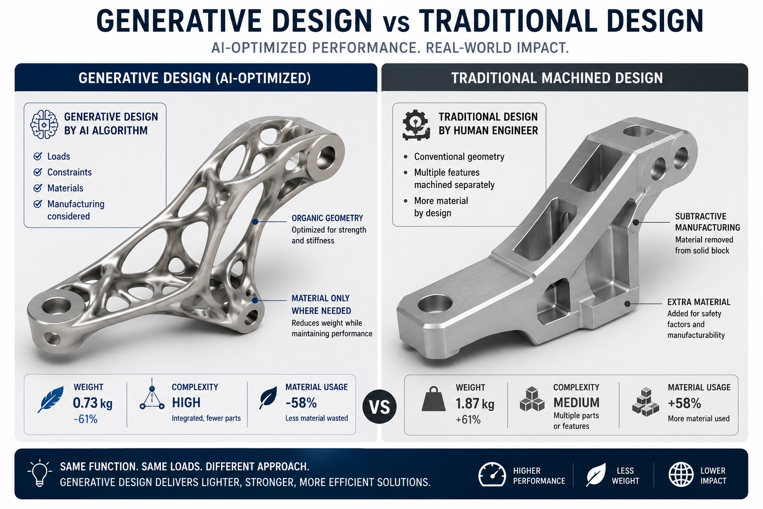
    Generative design uses AI algorithms to explore thousands of potential design geometries based on engineering constraints and objectives defined by the engineer: load cases, material constraints, manufacturing method, weight targets, and cost limits. The software produces optimised geometry candidates that are typically organic in shape, because they are mathematically optimised rather than geometrically intuited, and often achieve the same structural performance as a conventional design at 30 to 50 percent lower mass.

    Autodesk Fusion 360, SolidWorks with SOLIDWORKS Simulation, and nTop (formerly nTopology) are among the leading platforms offering generative design capabilities. SOLIDWORKS’ AI-powered co-pilot Aura, launched in 2026, adds conversational AI assistance directly into the design workflow, allowing engineers to query design performance, request automatic geometry modifications, and receive real-time suggestions.

    AI in Manufacturing: From Toolpath to Quality Control

    Beyond design, AI in manufacturing is being embedded into CNC machining, injection moulding, and additive manufacturing workflows. AI-driven toolpath optimisation in CAM software reduces machining time and tool wear. Computer vision systems on production lines detect surface defects in real time at accuracy levels that exceed human inspectors. Machine learning models monitor process parameters and adjust them automatically to maintain dimensional accuracy as tools wear.

    Career Impact:  The role of AI Systems Integration Engineer is already appearing on engineering job boards, requiring the ability to embed AI algorithms directly into mechanical systems while maintaining rigorous understanding of physical constraints. Engineers with combined mechanical and AI/ML competency are commanding premiums of 20 to 30 percent above peers without those skills.

    Advance 2: Metal Additive Manufacturing at Production Scale

    Metal additive manufacturing has crossed the threshold from prototyping tool to genuine production technology. This is arguably the single most structurally significant manufacturing advance of the past decade for mechanical engineers, because it removes geometric constraints that have governed component design since the invention of machining.

    Metal additive manufactured aerospace component cross-section showing internal lattice structure and complex cooling channels produced by laser powder bed fusion

    What Metal AM Enables That Machining Cannot

    Traditional subtractive manufacturing (machining) produces components by removing material from a solid block. This imposes fundamental geometric constraints: internal channels must be accessible to cutting tools, undercuts require special fixturing, and complex organic geometries are prohibitively expensive to machine. Metal additive manufacturing builds components layer by layer from metal powder or wire, removing virtually all geometric constraints. Internal lattice structures, conformal cooling channels, biomimetic organic geometries, and topology-optimised shapes can all be produced directly from CAD data.

    Key Metal AM Technologies in 2026

    • Laser Powder Bed Fusion (LPBF / SLM): The dominant technology for producing dense, high-accuracy metal parts in titanium, Inconel, stainless steel, and aluminium alloys. Used for aerospace brackets, medical implants, and tooling inserts.
    • Directed Energy Deposition (DED): Enables the addition of material onto existing components (repair and overhaul) and the production of large near-net-shape components. Used in aerospace repair, energy sector component refurbishment.
    • Binder Jetting: High-throughput, lower-cost process suited to high-volume production of smaller components in steel and copper alloys. Advancing rapidly toward automotive-scale deployment.
    • Wire Arc Additive Manufacturing (WAAM): Uses welding wire and an arc heat source to deposit large metallic structures at low cost. Suited for maritime and offshore structural components, large aerospace structural elements.

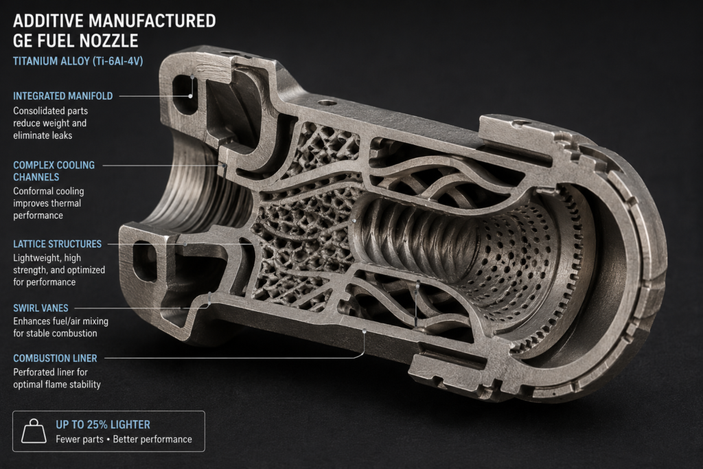
    The global additive manufacturing market was valued at approximately $21 billion in 2024 and is projected to reach $73 billion by 2031, with metal AM representing the fastest-growing segment. SpaceX’s Raptor engine uses 3D-printed metal components for its combustion chamber. GE Aviation produces more than 100,000 fuel nozzle tips annually using metal AM, achieving a component that is 25 percent lighter and five times more durable than its machined predecessor.

    Advance 3: Digital Twins Moving from Prototype to Standard Practice

    A digital twin is a real-time, high-fidelity virtual model of a physical system, continuously updated with live sensor data from its physical counterpart. The concept has existed in research for two decades. What is new is that the combination of affordable IoT sensors, cloud computing, and physics-based simulation has made digital twins practical and cost-effective at industrial scale.

    What Digital Twins Enable

    A well-implemented digital twin allows engineers to monitor asset health in real time, simulate the consequences of proposed changes before implementing them on the physical system, predict maintenance needs before failures occur, and optimise operational parameters continuously based on actual operating conditions rather than design assumptions. In industries where unplanned downtime is extremely costly, the return on investment is compelling: documented industrial deployments report reductions in unplanned downtime of 30 to 50 percent.

    Siemens, GE, and Rolls-Royce all operate digital twin programs for their turbine and engine products. Rolls-Royce’s IntelligentEngine initiative creates a digital twin for every engine it produces, enabling remote performance monitoring and predictive maintenance scheduling that has significantly reduced airline maintenance costs and in-service disruptions.

    Multi-Physics Simulation: Beyond Single-Domain Analysis

    Parallel to the digital twin advance, multi-physics simulation has become standard practice for complex mechanical systems. Where engineers once simulated structural, thermal, and fluid behaviour separately and sequentially, modern platforms such as ANSYS, Comsol Multiphysics, and Siemens NX allow simultaneous coupled simulation across multiple physics domains. For automotive power electronics cooling systems, for example, engineers now routinely model fluid flow, heat transfer, and structural stress simultaneously, a workflow that has been reported to reduce development time by 40 percent while improving design confidence.

    Advance 4: Collaborative Robotics and Adaptive Automation

    Industrial robotics is not new. What is new is collaborative robotics (cobots): robots designed to work alongside human workers in shared spaces, without safety cages, sensing proximity, adjusting force, and performing precision tasks in environments that are too hazardous or ergonomically demanding for humans.

    Why Cobots Are Changing Manufacturing

    Traditional industrial robots are programmed for highly repetitive tasks in precisely defined environments. They are expensive to reprogram, require significant safety infrastructure, and cannot safely share a workspace with humans. Cobots address all three limitations. They are force-limited, vision-guided, and easily reprogrammed by non-specialists through direct teaching (physically guiding the robot through a task). They are being deployed in small and medium manufacturers who could not previously justify robotic automation.

    The global industrial robotics market reached approximately $48 billion in 2024 and is projected to exceed $100 billion by 2030 according to the International Federation of Robotics (IFR). Autonomous Mobile Robots (AMRs), which navigate dynamically through warehouse and factory environments using LIDAR and computer vision, are now standard in logistics facilities operated by companies including Amazon, DHL, and Ocado.

    Engineering Reality Check:  Mechanical engineers are central to cobot and robot development, designing the structural frames, actuator systems, wrist mechanisms, and end effectors. The transition from rigid industrial robots to soft, compliant cobots requires deep mechanical engineering expertise in flexible mechanism design, contact mechanics, and force-controlled actuation, precisely the areas where mechanical engineers with robotics specialisation are most scarce and most valuable.

    Advance 5: Soft Robotics and Bio-Inspired Mechanical Systems

    Soft robotics represents one of the most philosophically significant departures from traditional mechanical engineering thinking. Conventional mechanical systems are built from rigid components: metal frames, hard actuators, stiff linkages. Soft robotics replaces rigid structures with compliant, deformable bodies made from elastomers, hydrogels, and pneumatically or thermally actuated smart materials, drawing direct inspiration from biological organisms.

    Why Soft Robots Solve Problems Rigid Robots Cannot

    Rigid robots interact with the world through precise, force-controlled contact. They excel at tasks with well-defined geometry and predictable environments. They struggle in unstructured environments, with fragile objects, in confined spaces, and in direct contact with human tissue. Soft robots, because they deform and conform rather than imposing rigid force, are inherently safer, more adaptable, and more capable in these scenarios.

    Applications are advancing rapidly: soft robotic grippers for food handling and agricultural harvesting (where fragile produce must be grasped without damage), soft robotic endoscopes and surgical tools that navigate the human body through natural orifices, wearable soft exosuits that augment human strength and assist post-stroke rehabilitation, and 4D-printed soft microrobots that change shape in response to temperature, magnetic fields, or chemical stimuli for targeted drug delivery and minimally invasive surgery.

    The soft robotics market was valued at approximately $2.5 billion in 2024 and is projected to reach $10.7 billion by 2030. Harvard’s Wyss Institute, MIT’s CSAIL, and a growing cohort of commercial startups are driving development, but the mechanical engineering principles at the heart of soft robotics, continuum mechanics, flexible beam theory, nonlinear elasticity, and fluid-structure interaction, are exactly the subjects covered in advanced ME programs.

    Advance 6: Mechanical Metamaterials and 4D Printing

    Mechanical metamaterials are engineered structures whose mechanical properties derive from their geometric architecture rather than the intrinsic properties of the material they are made from. By carefully designing the arrangement of unit cells at the micro or meso scale, engineers can produce structures with properties that no naturally occurring material possesses: negative Poisson’s ratio (expanding laterally when stretched), programmable stiffness, acoustic cloaking, and energy absorption profiles engineered to a specific crash event.

    From Lattice Structures to Programmable Matter

    The intersection of mechanical metamaterials and additive manufacturing has opened a new domain of engineering capability. Lattice-structured parts produced by metal LPBF can be designed to have tailored stiffness in specific directions, density distributions that match the load path through a component, and progressive crushing behaviour for energy absorption applications.

    4D printing extends this further by adding time as a design dimension. 4D-printed structures are made from stimuli-responsive materials (shape memory polymers, hydrogels, liquid crystal elastomers) that change shape, stiffness, or other properties in response to heat, moisture, light, or magnetic fields. Published research in 2026 and 2026 demonstrates 4D-printed metamaterials with programmable reconfiguration capability for applications including deployable aerospace structures, autonomous health-monitoring systems, biomimetic soft robotic actuators, and adaptive wearable devices.

    Research Frontier:  Magnetoactive metamaterials (MMs), which integrate magnetoactive soft composite materials with architected mechanical structures, can dynamically change their mechanical, acoustic, and elastic properties through the application of an external magnetic field. This enables tunable vibration dampers, shape-morphing medical devices, and remotely reconfigurable robotic systems, applications that were entirely in the realm of research science five years ago and are now moving toward early commercial deployment.

    Advance 7: Hydrogen Energy Systems and Mechanical Engineering

    Hydrogen is widely regarded as the most technically viable pathway to decarbonising industrial processes and long-distance transport that cannot be practically electrified. The mechanical engineering challenges of the hydrogen economy are enormous and diverse, spanning materials science, thermodynamics, fluid mechanics, and structural integrity.

    The Mechanical Engineering Challenges of Hydrogen

    Hydrogen is the smallest molecule in existence, which creates unique engineering challenges. It diffuses through many conventional materials, causing hydrogen embrittlement: a reduction in ductility and fracture toughness that can lead to unexpected failure in steel pressure vessels and pipelines. Mechanical engineers specialising in hydrogen systems engineering must select and qualify materials resistant to hydrogen embrittlement, design storage vessels that maintain structural integrity under cyclic pressurisation, and develop sealing systems capable of preventing the escape of a molecule that passes through most conventional seals.

    Cryogenic hydrogen storage (liquid hydrogen at -253 degrees Celsius) introduces a further set of thermal engineering challenges: insulation systems must prevent heat ingress at temperatures approaching absolute zero, and structural materials must maintain ductility and toughness at cryogenic temperatures where many metals become brittle.

    Hydrogen Turbines and Fuel Cell Mechanical Systems

    The adaptation of gas turbines to burn hydrogen rather than natural gas is a significant mechanical engineering undertaking. Hydrogen combustion produces higher flame temperatures and significantly different combustion dynamics than natural gas, requiring redesigned combustor liners, modified turbine blade cooling circuits, and new coating systems to handle the increased thermal load. Siemens Energy and GE Vernova are both conducting field trials of hydrogen-capable gas turbines, and the engineering demand for specialists in this area is projected to grow 45 percent by 2030 according to sector analysis.

    Advance 8: Electric Vehicle Powertrain and Thermal Engineering

    The global transition to electric vehicles is creating one of the largest structural shifts in automotive mechanical engineering since the introduction of computer-controlled fuel injection. By 2030, 40 percent of automotive engineering jobs are projected to require expertise in EV powertrain systems and AI-driven diagnostics, with traditional internal combustion engine roles transforming into energy optimisation and electromechanical systems engineering.

    Battery Thermal Management: The Critical Mechanical Engineering Problem in EVs

    Lithium-ion battery cells perform optimally within a narrow temperature range of approximately 15 to 35 degrees Celsius. Below this range, capacity drops sharply. Above it, degradation accelerates and thermal runaway (an uncontrolled exothermic reaction that can cause fire) becomes a risk. Battery thermal management system (BTMS) design is one of the most demanding thermal engineering challenges in current automotive work, requiring the design of cooling plates, phase-change material systems, and heat pipe networks that maintain uniform cell temperatures across a battery pack spanning hundreds of cells.

    Lightweight Structural Engineering for EVs

    Battery packs are heavy. A typical EV battery pack weighs 400 to 700 kilograms, placing significant mass at the vehicle’s base. Mechanical engineers working in EV structural design must offset this weight through aggressive lightweighting of the vehicle body and chassis using advanced aluminium alloys, carbon fibre composites, and topology-optimised structural components. Companies like Tesla and Rivian are prioritising lightweight material expertise, with composite engineers reportedly earning 20 percent higher salaries than equivalent conventional automotive roles.

    Advance 9: Advanced Composites and Smart Materials

    The materials available to mechanical engineers in 2026 are fundamentally more capable than those available a generation ago, and the pace of materials innovation is accelerating. Three areas are particularly significant: advanced composites, self-healing materials, and shape memory alloys.

    Carbon Fibre Reinforced Polymers (CFRP): Expanding from Aerospace to Mainstream

    Carbon fibre reinforced polymer composites offer specific stiffness and specific strength values that no metal alloy can match. Once confined to aerospace and motorsport, CFRP is now entering automotive, wind energy, medical devices, and consumer products as manufacturing processes have matured and costs have reduced. Automated Fibre Placement (AFP) and resin transfer moulding at scale are enabling the production of large composite structures at automotive production rates.

    Self-Healing Materials: Components That Repair Themselves

    Self-healing materials are a class of advanced engineering materials that can autonomously repair damage such as cracks, scratches, or delamination. They contain microencapsulated healing agents that release and polymerise when a crack propagates through the material, restoring structural integrity without human intervention. Published research from 2024 demonstrates self-healing polymer matrices for fibre composite structures with healing efficiency of 80 to 95 percent of original fracture toughness, opening potential applications in offshore wind turbine blades, pressure vessels, and aerospace panels that are difficult to inspect and repair conventionally.

    Shape Memory Alloys and Actuators

    Shape memory alloys (SMAs), most commonly Nitinol (nickel-titanium alloy), undergo a reversible phase transformation when heated or cooled, enabling them to recover a programmed shape after deformation. SMAs are used in stents, orthodontic wires, actuators in aerospace morphing structures, and thermal actuators in HVAC systems. Their capacity to serve simultaneously as structural material and actuation mechanism makes them particularly attractive for applications where conventional actuators (motors, hydraulics) are too heavy or too complex.

    Advance 10: Microelectromechanical Systems (MEMS) and Nanotechnology

    Microelectromechanical Systems (MEMS) are microscale devices that combine mechanical and electrical components on a single silicon or polymer chip, fabricated using semiconductor manufacturing processes. MEMS are not a new technology, but their capabilities, range of applications, and volume of deployment are expanding rapidly.

    MEMS Applications Transforming Industries

    MEMS accelerometers in every modern smartphone trigger airbags, enable screen rotation, and provide orientation data for augmented reality applications. MEMS pressure sensors monitor tyre pressure, blood pressure, and industrial process conditions continuously and wirelessly. MEMS microfluidic chips (lab-on-a-chip) perform medical diagnostic tests in minutes using a drop of blood, bringing laboratory-quality analysis to point-of-care settings globally.

    Nanomaterials: The Materials Science Frontier

    At the nanoscale, materials behave differently from their bulk counterparts, and this opens engineering opportunities that are not available at conventional scales. Graphene, carbon nanotubes (CNTs), and metallic nanoparticles are among the most engineered nanomaterials, offering extraordinary combinations of strength, electrical conductivity, and thermal conductivity. The global nanomaterials market, valued at $12.42 billion in 2023, is projected to grow at 15 percent annually through 2030, driven by demand from electronics, medical devices, energy storage, and structural composites.

    Advance 11: Space-Based Manufacturing and Extreme Environment Engineering

    The commercialisation of space is creating a new frontier for mechanical engineering that requires both extreme performance engineering and a fundamental rethinking of manufacturing logic. Space-based manufacturing is no longer purely speculative: NASA, ESA, and commercial operators are actively developing in-space manufacturing capabilities for structural components, optical fibres, pharmaceutical crystals, and semiconductor devices that can be produced with superior properties in the microgravity environment of orbit.

    Reusable Launch Systems: The Structural Engineering Achievement of the Decade

    The development of fully reusable launch vehicles by SpaceX (Falcon 9 and Starship) is perhaps the most demanding structural and thermal mechanical engineering achievement of the past decade. Rocket structures must survive launch loads, re-entry thermal gradients exceeding 1,600 degrees Celsius on heat shield surfaces, and precision propulsive landing, while being refurbishable and re-flyable with minimal inspection and maintenance. The fatigue analysis, thermal protection system design, and propellant system engineering required for reusable launch vehicle development represent the cutting edge of applied mechanical engineering.

    Extreme Environment Materials Engineering

    Beyond space, the demand for components that can survive extreme environments is growing in nuclear energy, deep-sea energy extraction, and high-performance aerospace. Next-generation nuclear reactors require structural materials that can maintain integrity under high-flux neutron bombardment, elevated temperatures, and corrosive coolants for decades without replacement. Oxide Dispersion Strengthened (ODS) steels and ceramic matrix composites (CMCs) are among the advanced materials being developed for these applications, both requiring sophisticated mechanical engineering analysis and manufacturing process development.

    Advance 12: Predictive Maintenance and Industrial IoT

    The combination of Industrial Internet of Things (IIoT) sensor networks and machine learning algorithms is transforming how mechanical systems are maintained. Traditional maintenance is either scheduled (replace after a fixed time or number of cycles regardless of actual condition) or reactive (repair after failure). Predictive maintenance uses continuous sensor data (vibration signatures, acoustic emissions, temperature distributions, oil particle counts) and machine learning models to predict when a component is approaching failure, allowing maintenance to be scheduled precisely when needed, not too early and not too late.

    What Predictive Maintenance Requires from Mechanical Engineers

    Implementing an effective predictive maintenance system requires mechanical engineers who understand both the physics of component degradation (which failure modes are occurring, why, and how they manifest in sensor signatures) and the data infrastructure for collecting, transmitting, and analysing large volumes of sensor data. This is precisely the cross-disciplinary skill set that defines the most sought-after mechanical engineers in 2026: deep domain knowledge of mechanical systems combined with data literacy and machine learning awareness.

    Rolls-Royce, Siemens, SKF, and dozens of industrial equipment manufacturers have deployed predictive maintenance systems that have documented reductions in unplanned downtime of 30 to 50 percent, maintenance cost reductions of 10 to 25 percent, and extensions in asset operating life. These are not marginal improvements: for a large industrial facility, they translate to savings of tens of millions of dollars annually.

    How These Advances Are Changing Mechanical Engineering Careers

    The latest advances in mechanical engineering are not abstract research topics for most of the profession. They are actively reshaping the skills that employers are looking for, the roles that are being created, and the salary premiums available to engineers who develop the right competencies.

    Technology AdvanceNew / Transformed RolesSkills RequiredSalary Premium (vs. Avg. ME)
    AI-Driven DesignAI Systems Integration Engineer; Generative Design SpecialistPython/ML basics, ANSYS/Fusion 360 with AI tools, topology optimisation+20 to 30%
    Metal Additive ManufacturingAM Process Engineer; DfAM Specialist; Powder MetallurgistLPBF/DED process knowledge, DfAM principles, metallurgy+15 to 25%
    Digital TwinsDigital Twin Engineer; Simulation Data EngineerIoT sensor integration, physics-based modelling, cloud platforms (Azure/AWS)+15 to 20%
    Cobots / RoboticsRobotics Mechanical Engineer; Cobot Integration SpecialistROS, robot kinematics, mechanism design, force-controlled actuation+15 to 25%
    Soft RoboticsSoft Robotics Engineer; Compliant Mechanism DesignerContinuum mechanics, elastomer materials, pneumatic actuation+20 to 30% (specialist scarcity)
    Hydrogen SystemsHydrogen Systems Engineer; Fuel Cell Mechanical EngineerHydrogen embrittlement, cryogenics, high-pressure vessel design, codes/standards+20 to 35%
    EV Powertrain / BTMSBTMS Engineer; EV Structural Engineer; Battery Integration EngineerThermal management, CFD, lightweight materials, battery cell chemistry basics+15 to 25%
    Predictive Maintenance / IIoTReliability Engineer with ML skills; IIoT Mechanical Systems EngineerVibration analysis, sensor systems, Python/MATLAB, machine learning basics+10 to 20%
    Strategic Career Advice:  The data is clear: mechanical engineers who develop depth in one or two of these advancing areas, while maintaining strong mechanical engineering fundamentals, are in the highest demand and command the strongest salary premiums. The most powerful combination in 2026 is strong classical ME foundations plus one high-growth specialisation (hydrogen, additive manufacturing, EV thermal systems, or AI-integrated design). Adding basic Python or MATLAB data skills amplifies the premium further in roles involving simulation, predictive maintenance, or digital twin development.

    Frequently Asked Questions (FAQ)

    What are the latest advances in mechanical engineering?

    The most significant latest advances in mechanical engineering in 2026 include AI-driven generative design, metal additive manufacturing at production scale, real-time digital twins, collaborative robotics and cobots, soft robotics and bio-inspired systems, mechanical metamaterials and 4D printing, hydrogen energy system engineering, electric vehicle thermal management, advanced composites and self-healing materials, MEMS and nanotechnology, space-based manufacturing, and IIoT-driven predictive maintenance. Each of these is being deployed at industrial scale and is creating new career opportunities for mechanical engineers.

    How is AI changing mechanical engineering?

    AI is changing mechanical engineering in several simultaneous ways: generative design algorithms explore thousands of optimised design geometries based on engineering constraints; AI-assisted CAM software optimises machining toolpaths and reduces tool wear; computer vision systems perform real-time quality inspection on production lines; machine learning models embedded in digital twins predict equipment failures before they occur; and AI-powered chatbot assistants in CAD platforms offer real-time design suggestions. Engineers with combined mechanical engineering and AI/ML competency are commanding salary premiums of 20 to 30 percent above peers without those skills.

    What is additive manufacturing in mechanical engineering?

    Additive manufacturing (3D printing) in mechanical engineering is a family of processes that build components layer by layer from digital design data, most commonly from metal powders, polymer filaments, or resins. For mechanical engineers, the most significant advance is metal additive manufacturing, which enables the production of complex geometries that cannot be machined, including internal lattice structures, conformal cooling channels, and topology-optimised organic shapes. The global additive manufacturing market was valued at $21 billion in 2024 and is projected to reach $73 billion by 2031.

    What is a digital twin in mechanical engineering?

    A digital twin in mechanical engineering is a real-time virtual model of a physical asset or system, continuously updated with live sensor data from its physical counterpart. It allows engineers to monitor asset health remotely, simulate the effect of proposed changes before implementing them, predict maintenance needs before failures occur, and optimise operational parameters based on actual conditions. Industrial deployments have documented reductions in unplanned downtime of 30 to 50 percent, and the digital twins market is projected to reach $110 billion by 2032.

    What is the future of mechanical engineering?

    The future of mechanical engineering is defined by the convergence of traditional physical engineering with digital intelligence, sustainable energy systems, and advanced materials. Key directions include: AI-assisted design becoming standard practice; metal additive manufacturing replacing machining for complex components; hydrogen and electrification reshaping energy and transport engineering; soft robotics expanding into healthcare and agriculture; and predictive maintenance transforming industrial operations. The U.S. BLS projects 11 percent employment growth from 2023 to 2033, with the highest demand in renewable energy, robotics, and AI-integrated engineering roles.

    What is soft robotics in mechanical engineering?

    Soft robotics in mechanical engineering is a sub-discipline that designs robots and actuators from compliant, deformable materials (elastomers, hydrogels, shape memory polymers) rather than rigid metal or plastic structures. Inspired by biological organisms, soft robots can safely interact with humans and delicate objects, navigate confined and unstructured environments, and change shape in response to environmental stimuli. Applications include surgical robots, agricultural harvesting systems, wearable exosuits, and 4D-printed microrobots for targeted drug delivery. The soft robotics market is projected to reach $10.7 billion by 2030.

    What are mechanical metamaterials?

    Mechanical metamaterials are engineered structures whose mechanical properties (stiffness, density, acoustic behaviour, Poisson’s ratio) derive from their geometric architecture rather than the intrinsic properties of their constituent material. By designing the arrangement of unit cells at the micro or meso scale, engineers can produce structures with properties not found in nature, such as negative Poisson’s ratio, programmable stiffness, and tailored energy absorption. Combined with 4D printing, mechanical metamaterials can be designed to change shape or properties in response to stimuli, enabling applications in deployable aerospace structures, adaptive wearables, and soft robotic actuators.

    How is mechanical engineering involved in the hydrogen economy?

    Mechanical engineering is central to the hydrogen economy across multiple technical dimensions: designing high-pressure storage vessels and pipelines that are resistant to hydrogen embrittlement, developing cryogenic insulation systems for liquid hydrogen storage, engineering combustor modifications to gas turbines for hydrogen firing, designing mechanical compression and liquefaction systems for hydrogen logistics, and developing fuel cell stack mechanical assemblies. The demand for hydrogen systems engineers is projected to grow 45 percent by 2030, with salary premiums of 20 to 35 percent above manufacturing averages.

    Conclusion

    The latest advances in mechanical engineering are not isolated innovations. They are interconnected, mutually reinforcing transformations that are collectively redefining what the discipline does, what tools it uses, what problems it can solve, and what it means to be competitively skilled as a practising engineer.

    AI-driven generative design changes what additive manufacturing can produce. Additive manufacturing enables mechanical metamaterial geometries that no other process can create. Digital twins close the loop between virtual design and physical reality, making predictive maintenance economically viable. Soft robotics and advanced materials are creating entirely new categories of mechanical devices. Hydrogen and electrification are reshaping propulsion engineering at its foundations.

    For students, the implication is clear: the most valuable mechanical engineering education in 2026 pairs rigorous classical engineering fundamentals with at least one of these advancing specialisations, plus data literacy sufficient to engage with AI tools, simulation platforms, and sensor-driven systems.

    For practising engineers, the message is equally direct: the engineers commanding the strongest salary premiums are those who have extended their classical training into these new domains. The field has never offered more opportunity for those willing to keep learning.

    Explore the broader context in our pillar guide What Is Mechanical Engineering?, understand the Frontiers of Mechanical Engineering for the research-level view, or review our guide to Mechanical Engineering Careers and Industries to see where these advances are creating the most new employment opportunities.

  • Version Control for Engineering Drawings | Revision Guide

    Version Control for Engineering Drawings | Revision Guide

    Picture this: your manufacturing team is three weeks into production, cutting steel and assembling components, when someone discovers they have been working from the wrong revision of a critical assembly drawing. The updated hole pattern from Rev C never made it to the shop floor. They have been building from Rev A. The cost? Thousands of dollars in rework, delayed shipment, and a client relationship that takes months to repair.

    This scenario plays out in engineering firms, manufacturing plants, and design offices every week. It is not a technology failure. It is a version control failure.

    Managing revisions in engineering drawings is one of the most overlooked yet consequential disciplines in technical work. Unlike software code, where a bad commit can be rolled back in seconds, a machined part built from the wrong revision may be impossible to undo. The stakes are real and the margin for error is slim.

    This guide walks you through everything you need to know about version control for engineering drawings: what it means, how revision systems work, what tools are available, and what best practices separate teams that get it right from those that constantly fight drawing chaos.

    Engineering drawing revision history timeline showing incremental design changes from Rev A to Rev F

    1. What Is Version Control for Engineering Drawings?

    Version control, in the context of engineering drawings, refers to the systematic process of tracking, managing, and preserving every change made to a technical drawing over its lifecycle. Each change is documented with a unique revision identifier, a description of what changed, who made the change, and when it was made.

    At its core, version control ensures that at any point in time, every person on a project is working from the correct, approved version of a drawing, and that the full history of previous revisions remains accessible for reference, audit, or analysis.

    This is fundamentally different from simply saving multiple copies of a file. True version control is structured, traceable, and governed by defined rules about how changes are approved and communicated.

    Key Terms You Need to Know

    • Revision: A formally approved change to a drawing, typically labeled alphabetically (Rev A, Rev B) or numerically depending on the organization’s standard.
    • Revision Block / Title Block: The section of a drawing, usually in the lower right corner, that records the revision history including revision letter, date, description, and authorization.
    • Release: The formal process of issuing a drawing for use in production or construction after it has been reviewed and approved.
    • ECO / ECR (Engineering Change Order / Request): A formal document that initiates, describes, and authorizes a change to an engineering drawing or design.
    • As-Built Drawing: A drawing updated after construction or manufacturing to reflect the actual final state of the built item.
    • Controlled Copy: An official version of a drawing distributed through a managed process, ensuring it matches the current approved revision.

    2. Why Drawing Revision Management Matters

    If you have worked in manufacturing, construction, aerospace, or any engineering-heavy field, you already know that drawings are not static documents. They evolve. Materials change. Tolerances are refined. Assembly sequences get optimized. Customer requirements shift mid-project.

    What separates high-performing engineering organizations from those constantly in firefighting mode is not the absence of change. It is the ability to manage change systematically.

    The Business Cost of Poor Revision Control

    Poor drawing revision management creates a cascade of downstream problems:

    • Rework and scrap costs: Parts manufactured to an outdated drawing must be scrapped or expensively reworked. In precision machining, a single wrong revision can cost thousands of dollars in material and labor.
    • Project delays: When teams cannot quickly identify which drawing revision is current, time is wasted chasing clarification instead of executing work.
    • Safety risks: In structural, aerospace, and medical device engineering, using a superseded drawing can have life-safety consequences. This is why regulatory bodies like the FAA and ISO mandate formal revision control procedures.
    • Audit failures: Companies in regulated industries are required to demonstrate traceability of design changes. Without proper version control, passing a quality audit becomes nearly impossible.
    • Communication breakdown: When suppliers, subcontractors, and internal teams operate from different revisions, collaboration breaks down. Finger-pointing replaces problem-solving.

    3. How Engineering Drawing Revision Systems Work

    Most engineering organizations follow a structured revision numbering convention. While the specifics vary by company and industry, the underlying logic is consistent.

    Alphabetical vs. Numerical Revision Schemes

    The two most common approaches are alphabetical and numerical revision systems. Each has practical advantages depending on the type of project and the organization’s workflow.

    SchemeFormatTypical Use CaseProsCons
    AlphabeticalRev A, B, C…General engineering, manufacturingSimple, widely understoodLimited to 26 revisions; ambiguity with I, O
    NumericalRev 1, 2, 3…Software-influenced teams, PLM systemsUnlimited revisions, easy sortingLess intuitive in traditional shops
    Alpha-NumericRev A1, A2, B1…Complex, multi-phase projectsTracks major/minor changesCan become confusing without clear rules
    Date-Based2024-03-15Construction as-builtsSelf-explanatory timestampsHard to determine sequence at a glance

    The Revision Block: The Heart of Drawing Version Control

    Every properly formatted engineering drawing includes a revision block, typically located in the title block area. This block is the official record of the drawing’s revision history and should include:

    • Revision letter or number
    • Date of revision
    • Description of the change (brief but specific)
    • Name or initials of the person who made the change
    • Authorization or approval signature

    The revision block should be updated every time a formal change is made. Informal or undocumented changes (sometimes called ‘pencil changes’ in traditional shops) are a major source of version control breakdown.

    The Role of the Engineering Change Order (ECO)

    For any organization handling product design, the ECO is the formal mechanism that bridges the gap between someone identifying a needed change and that change being officially incorporated into the drawing. A well-designed ECO process includes:

    1. Change Request: Anyone on the team can submit a request identifying the problem or improvement needed.
    2. Impact Assessment: Engineering reviews the request to understand how the change affects related drawings, parts, assemblies, and processes.
    3. Approval Workflow: The change goes through an approval chain (engineering, quality, manufacturing, program management depending on impact).
    4. Drawing Update: The drafter or engineer updates the drawing, increments the revision, and records the change in the revision block.
    5. Release and Distribution: The new revision is formally released and distributed to all stakeholders, and old revisions are clearly marked as superseded.
    Flowchart of an Engineering Change Order process showing steps from change request to drawing release and distribution

    4. Manual vs. Digital vs. PLM-Based Version Control

    The method an organization uses to manage drawing revisions has a massive impact on efficiency, accuracy, and scalability. There is no single right answer. The best approach depends on team size, project complexity, and industry requirements. Let us walk through the three primary models.

    Manual Revision Control (Paper and Shared Folders)

    Many small shops and independent contractors still manage drawings through physical files or shared network folders. This approach works at a small scale but introduces serious risk as teams grow.

    Common signs of a manual system include: print-and-mark revision tracking, emailed drawings with revision numbers in the filename, and a shared folder structure like ‘Engineering > Drawings > Current’ with a separate ‘Archive’ folder.

    The core problem with manual systems is that they rely entirely on human discipline. One person saving over the wrong file, or forgetting to move the old version to the archive, can create silent errors that do not surface until significant damage is done.

    Digital Version Control (CAD Software and EDM Systems)

    Modern CAD platforms including SolidWorks PDM, Autodesk Vault, PTC Windchill, and CATIA come with built-in document management and revision control capabilities. These systems track file versions at the software level, making it much harder (though not impossible) to lose or overwrite revision history.

    Key features to look for in a digital drawing management system include:

    • Check-in and check-out functionality to prevent simultaneous editing
    • Automatic version incrementing on save or release
    • Audit trail showing who made changes and when
    • Role-based access control (not everyone should be able to release drawings)
    • Search and retrieval by revision number, date, or associated project
    • Integration with CAD software to link drawing files directly to revision records

    PLM-Based Version Control (Enterprise-Scale)

    Product Lifecycle Management (PLM) systems like Siemens Teamcenter, PTC Windchill, and Dassault Enovia represent the most comprehensive approach to engineering drawing revision control. PLM systems manage not just the drawings themselves, but the entire product data ecosystem: BOMs, change orders, supplier drawings, manufacturing processes, and quality records.

    For large manufacturers, aerospace companies, and automotive OEMs, PLM is often mandatory. These systems ensure that every drawing revision is linked to its originating change order, the associated BOM impact has been assessed, and all downstream teams receive automatic notification when a new revision is released.

    The tradeoff is cost and complexity. PLM implementations require significant investment in software licensing, IT infrastructure, and training. They are overkill for a 10-person fabrication shop but essential for a tier-1 aerospace supplier.

    5. Best Practices for Managing Drawing Revisions

    Whether your team uses paper folders or a full PLM system, the following practices consistently separate organizations with clean revision control from those drowning in drawing chaos.

    Establish a Revision Numbering Convention and Stick to It

    Pick a revision scheme and document it formally. Define what triggers a new revision (versus an informal markup), how revisions are labeled, and where the revision history lives. Share this standard with every person who touches drawings, including external suppliers and contractors.

    Consistency is more important than the specific scheme you choose. A team using alphabetical revisions impeccably will outperform one with a sophisticated system applied inconsistently.

    Never Delete Old Revisions

    This one cannot be overstated. Superseded revisions must be retained, not deleted. Why? Because products already in service were built from those older revisions. If a field failure occurs, your maintenance team needs to know exactly what design was in place at the time of manufacture. If you have deleted Rev B because Rev C is current, you have lost critical traceability.

    In digital systems, superseded revisions should be moved to an ‘Obsolete’ status, not deleted from the database. They should still be searchable and accessible to authorized personnel but clearly marked so no one accidentally uses them for production.

    Use Meaningful Change Descriptions

    A revision block entry that says ‘Updated per ECO-1042’ is useful only if someone can look up ECO-1042. An entry that says ‘Updated per ECO-1042: changed hole pattern on flange face from 4x M6 to 6x M8 per customer RFI-217’ is genuinely informative to anyone reading the drawing years later without access to the ECO database.

    Train your team to write revision descriptions that stand alone. Future engineers, quality auditors, and production teams will thank you.

    Control Distribution of Drawings

    The best revision control system in the world fails if people can bypass it. Establish a single source of truth for current drawings, whether that is your PDM system, your PLM, or a strictly managed shared drive with clear folder governance.

    When a new revision is released, formally notify all stakeholders and pull back or obsolete distributed copies of the previous revision. In digital environments, this means updating the file status. In physical environments, it means collecting and stamping old prints as ‘superseded.’

    Separate Internal Working Revisions from Released Revisions

    Many teams use a preliminary revision scheme (often lowercase letters or draft numbers) for drawings that are in development but not yet formally released. This protects the integrity of the official revision record while still providing version tracking during the design phase.

    For example, a drawing might go through internal iterations a, b, c as the design evolves, then be formally released as Rev A when it is ready for production. This way, the official revision record stays clean and only reflects formally approved states.

    Engineering drawing title block showing revision history from Rev A to Rev D with change descriptions, dates, and initials

    Implement a Formal Drawing Review and Release Workflow

    Drawings should not be released directly by the person who created them. A formal review step, even a lightweight one for small teams, catches errors before they propagate into production. At minimum, define who can review drawings, who can approve them, and who can release them. These can be the same person in a small shop but the process should still be intentional.

    For higher-stakes drawings (safety-critical parts, customer-deliverable documents, regulatory submissions), require multi-discipline review including manufacturing, quality, and sometimes the customer.

    6. Common Revision Control Mistakes (and How to Avoid Them)

    Using File Names as the Version Control System

    File names like ‘bracket_assembly_FINAL_v3_REVISED_USE-THIS-ONE.dwg’ are a warning sign. When the file name is your only version indicator, you are one accidental save away from losing your revision history. Use a proper revision tracking system and keep file names simple and consistent.

    Maintaining Multiple ‘Current’ Folders

    Teams under pressure sometimes create parallel folder structures (‘Current,’ ‘Current-2024,’ ‘Latest from Supplier’) that each claim to hold the authoritative version. This leads directly to the scenario described in the introduction. Enforce a single source of truth.

    Skipping the Revision Block Update

    When a drawing is updated quickly or informally, it is tempting to skip updating the revision block. This creates a drawing that has changed physically but whose metadata says otherwise. Make revision block updates a non-negotiable step in the drawing change process, not an optional one.

    Not Linking Drawings to Change Orders

    A revision with no associated change order is a revision with no traceable rationale. Future engineers, auditors, and customers cannot understand why a change was made if it was never documented. Even for minor updates, a simple ECR takes five minutes and creates invaluable traceability.

    7. Tools and Software for Engineering Drawing Version Control

    Choosing the right tool depends heavily on your workflow, team size, and industry. Here is a practical overview of what is available across the spectrum.

    Tool / SystemTypeBest ForKey Feature
    SolidWorks PDM StandardCAD-Integrated EDMSmall to mid-size teams using SolidWorksCheck-in/out, vault storage, revision workflow
    Autodesk VaultCAD-Integrated EDMAutodesk Inventor / AutoCAD usersTight CAD integration, lifecycle management
    PTC WindchillFull PLMMid to large manufacturers, OEMsBOM management, multi-site collaboration
    Siemens TeamcenterFull PLMAerospace, automotive, defenseDigital twin integration, regulatory compliance
    OnshapeCloud CAD + PDMDistributed teams, cloud-first orgsBuilt-in branching, real-time collaboration
    SharePoint + Custom WorkflowDocument ManagementOrganizations already using Microsoft 365Low cost, familiar interface
    Git / Git LFSSoftware-style VCSTeams with CAD text formats (e.g. OpenSCAD)Branching, diffing, open source

    A Note on Git for Engineering Drawings

    Software developers use Git as their version control backbone, and some engineering teams have explored applying Git to CAD files. This works reasonably well for text-based CAD formats (OpenSCAD, FreeCAD, KiCad) where actual file differences can be compared line by line. For binary formats like CATIA or SolidWorks native files, Git stores the entire file on each commit rather than the difference, which becomes storage-intensive. Git LFS (Large File Storage) partially addresses this. For most traditional engineering workflows, a purpose-built PDM or PLM system will be more practical than Git.

    8. Version Control in Regulated and Aerospace Industries

    In regulated industries, drawing revision control is not a best practice. It is a legal and contractual requirement.

    ISO 7200 and Drawing Title Block Standards

    ISO 7200 defines the required fields for technical drawing title blocks used in ISO-compliant organizations. It specifies fields for legal owner, document status, revision identifier, dates, approvals, and related document references. Organizations seeking ISO certification are expected to maintain drawings that conform to this standard or an equivalent organizational standard derived from it.

    AS9100 and Aerospace Drawing Control

    The AS9100 quality management standard, used throughout the aerospace and defense supply chain, mandates rigorous control of technical documentation including engineering drawings. AS9100 requires that organizations control documents to ensure only the correct revision is available at points of use, changes are reviewed and approved by authorized personnel, the identity of the current document status is clear, and records of obsolete documents are maintained.

    Failure to demonstrate compliant drawing revision control can result in failed audits, lost contracts, and in the case of safety-critical parts, regulatory action.

    FDA and Medical Device Drawing Requirements

    Medical device manufacturers operating under FDA 21 CFR Part 820 (Quality System Regulation) and the ISO 13485 standard face similar requirements. Device History Records (DHR) must be traceable to specific drawing revisions. If a device is manufactured to a revision that differs from what was validated, it constitutes a serious regulatory non-conformance.

    FAQ:

    What is the difference between a revision and a version in engineering drawings?

    In engineering practice, a ‘revision’ typically refers to a formally approved and released change to a drawing, documented in the revision block. A ‘version’ is a more informal term and may refer to any iteration of a file, including working drafts not yet formally released. Some organizations use these terms interchangeably, but best practice is to reserve ‘revision’ for formally controlled changes only.

    How do you handle drawing revisions when working with external suppliers?

    When sharing drawings with external suppliers, always include the revision number prominently on the drawing and in any accompanying purchase order or work order documentation. Establish a formal process for notifying suppliers when a new revision is released, and confirm that they have received and acknowledged the update before production begins. Include drawing revision numbers in acceptance criteria and inspection records.

    Should you use letters or numbers for engineering drawing revisions?

    Either works, and the choice depends largely on organizational convention and industry norms. Alphabetical revisions (A, B, C) are traditional in manufacturing and aerospace. Numerical revisions (1, 2, 3) are common in software-influenced organizations and some PLM systems. What matters most is consistency: pick a scheme, document it, and apply it uniformly across all drawings.

    What should be included in a drawing revision description?

    A good revision description should be specific enough to be understood without referencing other documents. Include what changed (the specific geometry, dimension, note, or specification), why it changed (customer requirement, design improvement, manufacturing feedback), and the reference number of any associated change order. Aim for one to three sentences of clear, factual description.

    How long should you retain obsolete drawing revisions?

    Retention requirements vary by industry and contractual obligation. As a general rule, retain all superseded revisions for the full service life of the product plus the applicable statutory limitation period. In aerospace and defense, this often means 20 to 30 years or longer. In regulated industries, consult applicable standards (AS9100, ISO 13485, FDA QSR) and your legal counsel for specific requirements.

    Can you use cloud storage like Google Drive or Dropbox for engineering drawing version control?

    Cloud storage platforms can provide basic version history for files, but they are not purpose-built for engineering drawing revision control. They lack features like formal release workflows, revision block integration, role-based approval authority, and audit trails required by quality standards. They can serve as a step up from unmanaged shared drives for small teams, but growing organizations should invest in a proper PDM or EDM system.

    Conclusion:

    Version control for engineering drawings is ultimately about trust. When your manufacturing team picks up a drawing, they need to trust that it is the correct revision. When your quality auditor traces a field failure back to its source, they need to trust that the revision history is complete. When your customer asks for the design documentation package, they need to trust that what they receive reflects exactly what was built.

    No software system, however sophisticated, creates that trust on its own. It is built through disciplined processes, clear standards, and a team culture that treats drawing revision control not as administrative overhead but as a core engineering responsibility.

    Start where you are. If your organization is still managing revisions through file names and shared folders, move to a structured naming convention and a formal release process first. If you have a basic PDM system, audit how consistently it is being used and tighten the workflows. If you are at the PDM stage and scaling fast, evaluate whether a PLM investment is justified.

    The cost of getting revision control right is modest. The cost of getting it wrong, measured in rework, audit failures, and damaged customer relationships, is substantial.

  • Engineering Mechanics Explained: Complete Guide 2026

    Engineering Mechanics Explained: Complete Guide 2026

    Every structure that stands, every machine that moves, and every vehicle that travels owes its safe and predictable behaviour to one foundational discipline: engineering mechanics. It is the scientific backbone of engineering, the toolkit that allows engineers to move from “I think this will hold” to “I can prove this will hold, here is the calculation.”

    And yet, for many engineering students encountering it for the first time, engineering mechanics can feel abstract, disconnected from the real world, or simply overwhelming. A subject full of vectors, free body diagrams, Newton’s laws, and equilibrium equations does not always arrive with a clear sense of why it matters or how it connects to the things engineers actually build.

    This guide fixes that. It explains engineering mechanics from the ground up: what it is, how it is structured, what each branch covers, how its principles are applied in practice, which tools engineers use to apply them, and how mastery of the subject translates into a professional engineering career. Whether you are a first-year student facing your first mechanics module, a professional refreshing your foundations, or simply someone who wants to understand the science behind the built world, this is the most complete and readable explanation you will find.

    Free body diagram example showing a simply supported beam with applied loads, pin support reaction, and roller support reaction in engineering mechanics
    Quick Answer:  Engineering mechanics is the branch of applied science that uses the principles of physics and mathematics to predict and analyse how physical bodies respond to forces, motion, and deformation. It is the foundational discipline of virtually all engineering fields and is divided into three primary branches: statics (bodies in equilibrium), dynamics (bodies in motion), and mechanics of materials (how materials deform and fail under load).

    What Is Engineering Mechanics? A Clear Definition

    Engineering mechanics is the application of the principles of classical mechanics, a branch of physics, to solve practical engineering problems. It deals with the behaviour of physical bodies when subjected to forces or displacements, and the subsequent effects those forces and displacements have on the bodies and their surrounding environments.

    The word “engineering” in engineering mechanics is important. Pure or theoretical mechanics asks: “What happens?” Engineering mechanics asks: “What happens, and how do we use that knowledge to design something safe, efficient, and reliable?” The distinction is the difference between scientific knowledge and the professional application of that knowledge.

    At its core, engineering mechanics is concerned with three fundamental physical quantities: force, motion, and deformation. Every problem in engineering mechanics ultimately reduces to understanding how these three quantities interact in a specific physical situation.

    Simple Everyday Example:  When you sit on a chair, engineering mechanics explains why the legs do not buckle (statics), why the chair does not vibrate excessively when you move (dynamics), and why the material of the chair deforms slightly but springs back when you stand up (mechanics of materials). All three branches of engineering mechanics are at work simultaneously in that single, unremarkable act.

    The Full Map of Engineering Mechanics: How It Is Structured

    Most introductory resources present engineering mechanics as simply “statics and dynamics”. That is a significant oversimplification. The full discipline is structured as a hierarchy of sub-fields, each building on the one before it.

    Infographic comparing statics (bridge under static load) and dynamics (vehicle in accelerating motion) as the two primary branches of engineering mechanics.
    LevelSub-FieldWhat It StudiesPrerequisite
    FoundationClassical MechanicsThe general science of motion, force, and matter: Newton’s Laws, conservation of momentum, energyMathematics (vectors, calculus, differential equations)
    Primary Branch 1Rigid Body MechanicsBodies that do not deform under load: all statics and most dynamics problemsClassical mechanics
    Sub-branch 1aStaticsForces on bodies in equilibrium (at rest or constant velocity)Rigid body mechanics
    Sub-branch 1bDynamics: KinematicsDescription of motion (displacement, velocity, acceleration) without reference to forceStatics
    Sub-branch 1cDynamics: KineticsForces that cause or result from motion; Newton’s 2nd Law applied to moving bodiesKinematics
    Sub-branch 1dVibrationsOscillatory motion in mechanical systems; forced and free vibrations, resonanceKinetics
    Primary Branch 2Deformable Body Mechanics (Mechanics of Materials)How real materials stretch, compress, bend, and fail under loadStatics
    Sub-branch 2aStress and Strain AnalysisInternal force distribution and deformation in loaded bodiesMechanics of materials
    Sub-branch 2bFracture and Fatigue MechanicsCrack propagation, fatigue life prediction, failure analysisStress and strain analysis
    Sub-branch 2cContinuum MechanicsGeneralised treatment of both solid and fluid deformation under loadAdvanced mathematics
    Primary Branch 3Fluid MechanicsHow liquids and gases respond to forces; pressure, flow, viscosity, turbulenceClassical mechanics
    Sub-branch 3aHydrostaticsFluids at rest: pressure distribution, buoyancy, forces on submerged surfacesFluid mechanics
    Sub-branch 3bHydrodynamics / CFDFluids in motion: Bernoulli’s equation, pipe flow, aerodynamics, turbulenceHydrostatics

    This hierarchy matters because it explains the logical order in which engineering mechanics is taught. You cannot understand dynamics without statics. You cannot understand mechanics of materials without statics. You cannot understand vibrations without dynamics. The subject is hierarchical by nature, which is why first-year engineering students universally encounter statics before any other engineering mechanics topic.

    Why Engineering Mechanics Is Taught First

    Almost every accredited engineering degree in the world, regardless of whether it is mechanical, civil, aerospace, structural, chemical, or industrial, includes engineering mechanics in its first or second semester. This is not a coincidence or an academic tradition preserved from habit. There are precise and compelling reasons why engineering mechanics occupies this foundational position.

    It Is the Language of Engineering Analysis

    Engineering mechanics provides the conceptual vocabulary and analytical framework that every other engineering subject uses. Structural analysis uses statics. Machine design uses dynamics and mechanics of materials. Thermodynamics uses concepts of force and energy from mechanics. Fluid mechanics is itself a branch of engineering mechanics. Without a solid foundation in engineering mechanics principles, none of the more advanced engineering subjects can be properly understood.

    It Develops the Problem-Solving Mindset Engineering Requires

    Engineering mechanics is one of the most rigorous training grounds for the analytical problem-solving approach that all engineering practice demands. The discipline requires students to extract the physically relevant information from a real-world situation, draw a free body diagram, write the governing equations, solve for unknowns, check the result for physical plausibility, and present a clear, defensible answer. This disciplined problem-solving loop is the method all engineers use, regardless of their specialism.

    It Instils the Habit of Quantification

    A core engineering habit is that gut feelings and intuitions must always be tested against numbers. Engineering mechanics is where engineers first learn to be quantitative about the physical world: to ask not just “will this beam bend?” but “by how much will it deflect under this load, and is that deflection within the allowable limit?” This habit of quantification is what distinguishes professional engineering from guesswork.

    Historical Context:  The formalisation of engineering mechanics as a taught discipline dates to the 18th century and the work of mathematicians and physicists including Leonhard Euler, Joseph-Louis Lagrange, and later Augustin-Louis Cauchy. Euler’s equations of motion for rigid bodies, Lagrange’s analytical mechanics, and Cauchy’s stress tensor are all contributions that still appear, in simplified form, in first-year engineering mechanics textbooks today.

    Newton’s Laws of Motion: The Engine of Engineering Mechanics

    The entire edifice of engineering mechanics rests on three laws formulated by Sir Isaac Newton in 1687. Understanding these laws at the level of a working engineer, not just a physics student, is the single most important conceptual foundation in the discipline.

    Newton’s First Law: The Law of Inertia

    A body remains at rest, or continues to move in a straight line at constant velocity, unless acted upon by a net external force.

    Engineering application: This law is the conceptual foundation of statics. If a structure is at rest, the net force and net moment acting on it must both equal zero. That is the condition of static equilibrium, and it is the governing principle for every static analysis in structural and mechanical engineering. It is also why a satellite in orbit does not need continuous thrust to stay in motion: there is no net force opposing it in the vacuum of space.

    Newton’s Second Law: The Law of Acceleration

    The net force acting on a body is equal to the product of its mass and its acceleration: F = ma.

    Engineering application: This is the governing equation of kinetics, the branch of dynamics that deals with forces and motion. It is used to calculate the braking distance of a vehicle, the thrust required to accelerate a rocket, the force on a connecting rod in a reciprocating engine, and the loads transmitted through a vehicle suspension system during a pothole impact. It is perhaps the single most applied equation in all of mechanical engineering.

    Newton’s Third Law: The Law of Action and Reaction

    For every action there is an equal and opposite reaction.

    Engineering application: This law explains why a rocket accelerates in one direction by expelling mass in the other. It explains why a beam exerts an upward reaction force on a support equal to the downward load the beam carries. It is why the analysis of forces in any connected system must account for reaction forces at every joint, support, and contact point. In structural analysis, identifying and correctly calculating reaction forces is one of the most fundamental skills a student of engineering mechanics must develop.

    Newton’s LawStatementPrimary Mechanics BranchKey Engineering Applications
    First Law (Inertia)A body at rest or constant velocity has zero net forceStaticsStructural support design, bridge analysis, building load calculations, static equilibrium of machines
    Second Law (F = ma)Net force equals mass times accelerationDynamics (Kinetics)Vehicle braking, engine load analysis, rocket propulsion, crash mechanics, earthquake response
    Third Law (Action-Reaction)Every force has an equal and opposite reaction forceStatics and DynamicsReaction forces at supports, joint loads in trusses, thrust and propulsion, ground contact forces

    Branch 1: Statics Explained in Full

    Statics is the branch of engineering mechanics that studies the behaviour of bodies under forces that produce a state of equilibrium: a condition where there is no net force and no net moment (turning effect) acting on the body. In simple terms, statics is the study of things that are not accelerating.

    The name “statics” can be misleading. A body does not need to be literally stationary to be in static equilibrium. A car travelling at constant velocity on a straight road is in dynamic equilibrium: the driving force exactly balances the drag and rolling resistance, producing zero net force and zero acceleration. Statics applies to both these situations.

    The Two Conditions of Static Equilibrium

    For any body to be in static equilibrium, two conditions must be simultaneously satisfied:

    • The sum of all forces acting on the body must equal zero (translational equilibrium: the body does not accelerate in any direction).
    • The sum of all moments (torques) acting on the body must equal zero (rotational equilibrium: the body does not rotate).

    In two-dimensional problems (the vast majority of introductory statics), this produces three scalar equations: the sum of forces in the x-direction equals zero, the sum of forces in the y-direction equals zero, and the sum of moments about any chosen point equals zero. These three equations can be used to solve for up to three unknown forces or reactions.

    Core Concepts in Statics

    Force vectors and resultants: All forces are vectors: they have both magnitude and direction. When multiple forces act on a body, they can be combined into a single resultant force using vector addition.

    Moments and torques: A moment is the turning effect of a force about a point. It is calculated as the product of the force magnitude and the perpendicular distance from the line of action of the force to the point (the moment arm). Moments are responsible for bending in beams and rotation in mechanisms.

    Support reactions: Real structures are supported in ways that prevent certain types of motion. A pin support prevents translation but allows rotation. A fixed support prevents both translation and rotation. Engineering mechanics provides the tools to calculate the reaction forces and moments at these supports.

    Trusses and frames: A truss is a structure made of straight members connected at joints, designed to carry loads efficiently. The method of joints and the method of sections are standard techniques in statics for determining the forces in individual truss members.

    Friction: Coulomb friction is the tangential resistance force between surfaces in contact. Statics includes the analysis of systems where friction plays a role, such as wedges, screws, belt drives, and braking systems.

    Real-World Applications of Statics

    ApplicationHow Statics Is Used
    Bridge designCalculating support reactions, member forces in trusses, and stability under traffic loads
    Building structural analysisEnsuring floors, beams, and columns can safely carry occupancy and wind loads without collapsing
    Crane and lifting equipmentDetermining the stability of lifting arms and calculating loads on cables and pulleys
    Bolt and fastener designCalculating the shear and tensile loads on fasteners in mechanical assemblies
    Ergonomic tool designAnalysing the forces and moments at the hand and wrist to minimise repetitive strain risk
    Dam wall designCalculating the hydrostatic pressure distribution and overturning moment from retained water

    Branch 2: Dynamics Explained in Full

    Dynamics is the branch of engineering mechanics that deals with bodies in motion, and specifically with cases where the motion involves acceleration. While statics describes equilibrium, dynamics describes change: changing velocity, changing direction, and the forces responsible for those changes.

    Dynamics is divided into two distinct sub-areas that are often studied sequentially: kinematics and kinetics. Understanding the distinction between these two is one of the first conceptual milestones in any dynamics course.

    Kinematics: Describing Motion Without Forces

    Kinematics is the purely geometric description of motion. It deals with how position, velocity, and acceleration relate to each other and to time, without asking what forces caused the motion. A kinematic analysis of a car journey calculates displacement, speed, and acceleration purely from the geometry of the motion.

    Key kinematic quantities include: displacement (change in position), velocity (rate of change of displacement), acceleration (rate of change of velocity), and angular equivalents of each for rotating bodies. Kinematics is particularly important in the design of mechanisms: gear trains, cam-follower systems, linkages, and robotic arms, where the designer needs to understand the motion geometry before analysing the forces.

    Kinetics: Relating Forces to Motion

    Kinetics applies Newton’s Second Law (F = ma) to relate the forces acting on a body to its resulting acceleration. Where kinematics asks “how does the body move?”, kinetics asks “why does the body move that way, and what force is required to produce that motion?”

    Kinetics methods include Newton-Euler direct application (summing forces and moments), work-energy methods (relating force and displacement to changes in kinetic energy), and impulse-momentum methods (relating force and time to changes in momentum). Each method has situations where it is particularly efficient, and a skilled engineer chooses the most appropriate method for each problem.

    Vibrations: The Dynamic Behaviour of Elastic Systems

    Vibrations is a sub-discipline of dynamics that studies oscillatory motion. Almost every mechanical system vibrates to some degree when disturbed, and understanding and controlling those vibrations is critically important in engineering. Excessive vibration causes fatigue failure, noise, discomfort, and loss of precision.

    Key concepts in vibration analysis include natural frequency (the frequency at which a system naturally oscillates when disturbed), resonance (the catastrophic amplification of vibration that occurs when an excitation frequency matches the natural frequency), damping (energy dissipation that reduces vibration amplitude), and forced vibration (oscillation driven by a sustained external force).

    Famous Engineering Failure: Resonance in Action:  The Tacoma Narrows Bridge collapsed in 1940 because wind-induced oscillations matched the bridge’s natural frequency, causing resonance. The amplitude of vibration grew until the structure tore itself apart. This disaster fundamentally changed how engineers account for dynamic loads and aerodynamic effects in bridge design, and it remains the most cited example of resonance failure in engineering education worldwide.

    Real-World Applications of Dynamics

    ApplicationHow Dynamics Is Used
    Automotive engineeringCrash analysis, suspension dynamics, engine vibration, drivetrain load calculation, ABS braking system design
    Aerospace engineeringFlight dynamics, landing gear impact loads, aeroelastic analysis, satellite orbit mechanics, launch vehicle trajectory
    RoboticsJoint torque calculations, trajectory planning, dynamic stability of walking robots, end-effector force control
    Rotating machineryBalancing of rotating components, shaft critical speeds, bearing load analysis in turbines and motors
    Earthquake engineeringDynamic response of structures to ground motion; resonance avoidance in building and bridge design
    Sports engineeringBiomechanical analysis of athletic motion; equipment dynamics in golf clubs, tennis rackets, bicycle frames

    Branch 3: Mechanics of Materials (Strength of Materials) Explained

    Statics and dynamics treat bodies as rigid: they analyse forces and motion without considering how the material of a body deforms under those forces. Mechanics of materials (also called strength of materials) removes that simplification and asks: given the forces a component must carry, how does the material actually deform, and will it survive?

    This branch of engineering mechanics bridges the gap between theoretical statics and practical design. Knowing the forces on a beam from a statics analysis is only the first step. The second step, which mechanics of materials provides, is determining whether a given material and cross-sectional shape can carry those forces without yielding, fracturing, or deflecting beyond acceptable limits.

    Stress and Strain: The Language of Material Behaviour

    Stress is the internal force per unit area within a material, measured in Pascals (Pa) or pounds per square inch (psi). It represents how intensely a material is being loaded at any given point. Strain is the ratio of deformation to original dimension: a dimensionless measure of how much the material has changed shape relative to its unloaded state.

    The relationship between stress and strain is described by a material’s stress-strain curve. In the elastic region (below the yield strength), stress and strain are proportional, described by Hooke’s Law: stress = E x strain, where E is the Young’s modulus of elasticity, a material property describing stiffness. Beyond the yield point, permanent (plastic) deformation occurs.

    Stress-strain curve diagram for a typical engineering material showing elastic region, yield strength, plastic deformation, and ultimate tensile strength

    Types of Stress in Engineering Components

    • Axial (normal) stress: Stress acting perpendicular to a cross-section, caused by tensile or compressive forces along a member’s axis. Applicable to columns, tie rods, and fasteners.
    • Shear stress: Stress acting parallel to a cross-section, caused by forces that tend to cause sliding failure. Critical in bolts, welds, and shaft keyways.
    • Bending stress: Stress distribution across the cross-section of a beam due to a bending moment. Maximum at the outer fibres, zero at the neutral axis. Governs the design of most structural beams and shafts.
    • Torsional stress: Stress caused by twisting moments (torques) applied to shafts. Critical in drive shafts, bolts, and any rotating component.
    • Combined loading: Most real components experience several stress types simultaneously. Combined loading analysis and failure criteria such as Von Mises and Tresca determine whether a component will survive the combined stress state.

    Buckling: The Failure Mode Unique to Compression

    Buckling is a sudden failure mode that can occur in slender compression members (columns) well below the material’s yield stress. It is a stability failure, not a strength failure: the column becomes geometrically unstable and bends sideways catastrophically. Euler’s buckling formula gives the critical compressive load above which a column will buckle, and it is one of the most important results in structural engineering.

    Branch 4: Fluid Mechanics as Part of Engineering Mechanics

    Fluid mechanics is the branch of engineering mechanics that studies the behaviour of fluids (liquids and gases) under the action of forces. It is sometimes treated as a standalone discipline, but it is deeply rooted in the same physical principles (Newton’s laws, conservation of energy, conservation of mass) that govern solid mechanics.

    Engineers encounter fluid mechanics problems in an enormous range of contexts: the flow of water through pipes in a building, the aerodynamics of a vehicle body, the lubrication of a bearing, the cooling of a computer chip, the thrust generated by a jet engine, and the pressure distribution on a dam wall. Without a working understanding of fluid mechanics principles, mechanical and civil engineers could not design any of these systems.

    Hydrostatics vs. Hydrodynamics

    Hydrostatics deals with fluids at rest. Its primary concerns are pressure distribution in stationary fluids, buoyancy forces on submerged objects (described by Archimedes’ principle), and forces on submerged surfaces such as dam walls and tank floors.

    Hydrodynamics (fluid dynamics) deals with fluids in motion. It analyses how velocity, pressure, and density change through a flowing fluid system. Bernoulli’s equation is the most famous result of fluid dynamics, relating fluid speed, pressure, and elevation in an ideal (frictionless, incompressible) flow. Real flows involve viscosity and turbulence, requiring the full Navier-Stokes equations, which can generally only be solved numerically using Computational Fluid Dynamics (CFD) software.

    Branch 5: Continuum Mechanics and Advanced Applications

    Continuum mechanics is the generalised mathematical framework that treats both solid and fluid mechanics within a single unified theory. It assumes that matter is continuously distributed throughout a body (as opposed to treating materials as collections of discrete atoms), and it uses tensor mathematics to describe stress, strain, and deformation in three dimensions.

    Continuum mechanics provides the theoretical foundation for advanced finite element analysis, computational fluid dynamics, and the analysis of complex materials such as polymers, biological tissues, and composite materials that do not behave in the simple linear-elastic manner assumed by introductory mechanics of materials.

    While continuum mechanics is an advanced topic typically encountered at postgraduate level, its practical consequences appear in everyday engineering tools. When a mechanical engineer uses ANSYS or Abaqus to run a finite element analysis on a complex 3D part, the mathematical engine underneath that simulation is built on continuum mechanics principles.

    Free Body Diagrams: The Most Important Tool in Engineering Mechanics

    If there is one practical skill that is absolutely central to engineering mechanics, it is the ability to draw an accurate free body diagram (FBD). An FBD is a simplified sketch of a body or system, isolated from its surroundings, showing all the external forces and moments acting on it. It is the engineer’s method of translating a complex physical situation into a tractable mathematical problem.

    How to Draw a Free Body Diagram: Step by Step

    1. Identify the body of interest: Decide clearly which object or system you are analysing. Draw it in isolation, separated from everything it contacts.
    2. Identify all external forces: Include applied loads (weights, pressures, applied forces), support reactions (from pins, rollers, fixed supports), and contact forces (friction, normal contact forces at surfaces).
    3. Represent each force as a vector: Show the direction, line of action, and point of application of each force. Label each force with a symbol (F1, W, R_A, etc.).
    4. Establish a coordinate system: Choose x and y axes (and z for 3D problems) to resolve forces into components.
    5. Write the equilibrium equations: For statics, set sum of forces and sum of moments equal to zero. For dynamics, set sum of forces equal to ma (Newton’s Second Law).
    6. Solve for unknowns: Use the equations to calculate unknown forces, reactions, or accelerations.
    Pro Tip:  The quality of a free body diagram determines the quality of the subsequent analysis. An incomplete or incorrectly drawn FBD will produce wrong answers even with perfect mathematics. Experienced engineers draw FBDs carefully, checking that every contact surface, every support, and every applied load is accounted for before writing a single equation. This habit, developed in engineering mechanics courses, is one of the most transferable analytical skills in the entire engineering curriculum.

    Engineering Mechanics vs. Theoretical Mechanics: What Is the Difference?

    A question that occasionally arises is: how does engineering mechanics differ from theoretical or classical mechanics as studied by physicists?

    AspectEngineering MechanicsTheoretical / Classical Mechanics
    Primary GoalProvide tools to design and analyse safe, functional engineering systemsUnderstand the fundamental laws governing physical reality
    Mathematical DepthApplied mathematics: vectors, basic calculus, differential equationsAdvanced mathematics: Hamiltonian mechanics, Lagrangian mechanics, tensor calculus
    Approach to ProblemsIdealised models designed to be tractable and practically usefulGeneralised, abstract formulations applicable to all physical systems
    Treatment of ConstraintsPractical support conditions, friction, and contact modelled pragmaticallyHolonomic and non-holonomic constraints treated with full generality
    OutputForces, stresses, deflections, accelerations: numbers that inform design decisionsEquations of motion, conservation laws, symmetry principles: fundamental understanding
    Who Studies ItAll engineering students; foundation of engineering practicePhysics students, applied mathematicians, research engineers at advanced level

    Engineering Mechanics vs. Mechanical Engineering: Understanding the Distinction

    These two terms are frequently confused, even by people within the engineering profession. The distinction is clear and important.

    Engineering mechanics is a subject or scientific discipline: a specific body of knowledge about forces, motion, and deformation. It is a foundational subject studied across many engineering programs.

    Mechanical engineering is a professional field and degree program: a comprehensive engineering discipline that uses engineering mechanics as one of its foundational tools, alongside thermodynamics, fluid mechanics, manufacturing, materials science, design, and control systems.

    The analogy: engineering mechanics is to mechanical engineering what grammar is to literature. You cannot write well without knowing grammar, but knowing grammar does not make you a novelist. Engineering mechanics is the grammatical foundation; mechanical engineering is the full creative and professional practice built on that foundation.

    AspectEngineering MechanicsMechanical Engineering
    What it isA foundational scientific discipline: the study of forces, motion, and deformationA professional engineering field: broad application of science to design, build, and maintain mechanical systems
    ScopeFocused: mechanics of rigid bodies, deformable bodies, and fluidsBroad: encompasses EM plus thermodynamics, design, manufacturing, controls, materials science
    Studied byStudents across all engineering disciplines in first/second yearMechanical engineering students specifically, plus relevant electives in related programs
    OutputAnalytical results: forces, stresses, deflections, motionsEngineering products: machines, systems, devices, processes
    RelationshipEngineering mechanics is a foundational component of mechanical engineeringMechanical engineering is the broader discipline that applies EM and many other tools

    How Engineering Mechanics Is Applied Across Industries

    The principles of engineering mechanics are applied in some form in virtually every industry that involves physical systems. The following examples illustrate how specific concepts from the discipline translate into real engineering work.

    IndustryEngineering Mechanics Concepts AppliedSpecific Example
    AutomotiveStatics (load paths), dynamics (crash analysis, NVH), mechanics of materials (fatigue), fluid mechanics (aerodynamics)FEA crash simulation to meet Euro NCAP safety ratings; suspension kinematics design for handling performance
    AerospaceStructural statics, flight dynamics, aeroelasticity, fracture mechanics, fluid mechanics (CFD)Wing spar stress analysis; flutter analysis to prevent resonance-induced structural failure in flight
    Civil / StructuralStatics (truss and frame analysis), dynamics (seismic response), mechanics of materials (beam design)Design of a reinforced concrete floor slab to carry specified occupancy loads with controlled deflection
    Energy (Oil, Gas, Renewables)Statics (pipe stress), dynamics (vibration of pipelines and turbines), fluid mechanics (pipe flow)Wind turbine blade structural optimisation; offshore pipeline fatigue life assessment
    Robotics and AutomationKinematics (path planning), kinetics (joint torque), statics (payload capacity)Calculation of motor torques required at each joint of a robotic arm to lift a specified load
    Biomedical / Medical DevicesStatics and mechanics of materials (implant load bearing), biomechanics (human joint forces)Hip replacement implant design: ensuring the prosthesis can survive 30 years of walking loads without fatigue fracture
    ManufacturingStatics (fixture design), dynamics (machine tool vibration), mechanics of materials (forming operations)Press tool design: calculating die forces and spring-back in sheet metal forming; avoiding chatter in CNC machining
    Consumer ProductsStatics and mechanics of materials (structural adequacy), dynamics (drop test simulation)Laptop chassis design: ensuring structural integrity under drop impact and sustained keyboard typing loads

    Modern Tools Used to Apply Engineering Mechanics

    While the principles of engineering mechanics are centuries old, the tools that engineers use to apply those principles have been transformed by computing. Modern engineering practice relies on a combination of hand analysis (for checking, scoping, and understanding) and powerful software tools (for high-fidelity analysis of complex systems).

    Finite Element Analysis (FEA) Software

    FEA software such as ANSYS, Abaqus, and SolidWorks Simulation numerically solves the governing equations of solid mechanics across complex 3D geometries by dividing them into thousands of small elements. FEA allows engineers to determine stress distributions, deflections, natural frequencies, and buckling loads in components too geometrically complex for analytical hand calculation. Proficiency in at least one FEA package is an expected skill for most structural, mechanical, and aerospace engineering roles.

    Computational Fluid Dynamics (CFD) Software

    CFD tools such as ANSYS Fluent, OpenFOAM, and STAR-CCM+ solve the Navier-Stokes equations numerically across complex fluid domains. They enable engineers to analyse airflow around vehicle bodies, thermal management in electronics, combustion in engines, and pressure drops in pipe networks, without physical wind tunnels or flow experiments in many cases.

    Multi-Body Dynamics (MBD) Software

    Multi-body dynamics tools such as Adams (MSC Software) and SIMPACK simulate the kinematic and dynamic behaviour of mechanical systems with multiple interconnected rigid or flexible bodies. They are used extensively in automotive suspension analysis, robotic mechanism design, and machinery simulation.

    Mathematical and Programming Tools

    MATLAB remains the dominant tool for engineering calculation, data analysis, and numerical simulation in academic and industrial settings. Python is increasingly used for engineering calculation scripting, particularly in research and simulation automation. Both are tools that any modern engineer working in analysis and simulation should be proficient with.

    Industry Trend:  The integration of AI and machine learning into engineering simulation workflows is accelerating. Physics-informed neural networks (PINNs), for example, use machine learning to solve partial differential equations at speeds that traditional FEA cannot match. Mechanical engineers who understand both the classical mechanics principles and the emerging AI-assisted simulation tools will be significantly better positioned in the engineering job market over the next decade.

    Career Paths Built on Engineering Mechanics

    Mastery of engineering mechanics is the entry qualification for a range of highly specialised and well-compensated engineering career paths. The following roles are directly and explicitly built on engineering mechanics expertise.

    Career RoleIndustryMechanics Knowledge Central To the RoleTypical Tools
    Structural Analyst / Stress EngineerAerospace, automotive, defence, energyStatics, mechanics of materials, FEA, fracture mechanics, fatigue analysisANSYS, Nastran, Abaqus, hand calculation
    Dynamics / NVH EngineerAutomotive, aerospace, rotating machineryDynamics, vibrations, modal analysis, transfer function analysisMATLAB, Adams, ANSYS, experimental modal testing equipment
    CFD EngineerAerospace, automotive, energy, HVACFluid mechanics, heat transfer, boundary layer theoryANSYS Fluent, OpenFOAM, STAR-CCM+, Python
    Robotics / Mechanisms EngineerRobotics, automation, medical devicesKinematics, kinetics, rigid body dynamics, mechanism synthesisAdams, SolidWorks, MATLAB/Simulink, ROS
    Geotechnical / Civil Structural EngineerCivil, infrastructure, constructionStatics, soil mechanics, structural analysis, mechanics of materialsAutoCAD Structural, SAP2000, ETABS
    Biomechanics EngineerMedical devices, sports science, rehabilitationStatics, dynamics, mechanics of materials, continuum mechanicsANSYS, Mimics, custom FEA code, motion capture systems
    Research / Academic EngineerUniversities, government labs, R&D centresAll branches of engineering mechanics at advanced levelCustom simulation codes, MATLAB, Python, FEA/CFD suites

    MIT OpenCourseWare provides free access to engineering mechanics course materials

    Frequently Asked Questions (FAQ)

    What is engineering mechanics in simple terms?

    Engineering mechanics is the science of how forces affect physical objects: whether they make things move, deform, or stay still. It uses the principles of physics and mathematics to predict how structures, machines, and materials will behave under loads, allowing engineers to design things that are safe, reliable, and efficient. It is taught to all engineering students because its principles underpin virtually every other engineering discipline.

    What are the main branches of engineering mechanics?

    The main branches of engineering mechanics are: statics (forces on bodies in equilibrium), dynamics (forces on bodies in motion, subdivided into kinematics and kinetics), mechanics of materials (how materials deform and fail under load), and fluid mechanics (how liquids and gases respond to forces). Advanced topics include vibrations, fracture mechanics, and continuum mechanics.

    What is the difference between statics and dynamics?

    Statics studies bodies that are in equilibrium: bodies at rest or moving at constant velocity, where the net force and net moment are both zero. Dynamics studies bodies that are accelerating: bodies whose velocity is changing in magnitude or direction, driven by a net unbalanced force. Statics is generally taught before dynamics because static equilibrium analysis is a prerequisite for most dynamic analysis methods.

    What is a free body diagram in engineering mechanics?

    A free body diagram (FBD) is a simplified sketch of a body or system, drawn in isolation from its surroundings, that shows all the external forces and moments acting on it. FBDs are the primary analytical tool in engineering mechanics: they translate a complex physical situation into a set of forces and moments that can be expressed as mathematical equations and solved. Drawing accurate free body diagrams is one of the most important practical skills in all of engineering analysis.

    What is the difference between kinematics and kinetics?

    Kinematics describes motion (position, velocity, acceleration) without reference to the forces that cause it. It answers the question: how does the body move? Kinetics relates forces to motion through Newton’s Second Law (F = ma). It answers the question: what forces are required to produce this motion, or what motion results from these forces? Kinematics is studied first because understanding motion geometry is a prerequisite for applying force-motion relationships in kinetics.

    Why is engineering mechanics important?

    Engineering mechanics is important because it provides the mathematical and physical tools that allow engineers to prove a design will work safely before anything is built. Without it, structural collapses, mechanical failures, and unsafe products would be far more common. It is the analytical foundation of civil, mechanical, aerospace, and structural engineering, and its principles are applied in virtually every physical engineering system in the world. Mastery of engineering mechanics is also one of the strongest predictors of success in advanced engineering study and practice.

    What is the difference between engineering mechanics and mechanical engineering?

    Engineering mechanics is a subject: a specific scientific discipline covering forces, motion, and deformation, studied as a foundational course across all engineering programs. Mechanical engineering is a professional field and degree program that is much broader in scope, covering thermodynamics, fluid mechanics, manufacturing, design, materials science, and control systems in addition to engineering mechanics. Engineering mechanics is one foundational component of mechanical engineering, not the entirety of it.

    How is engineering mechanics used in real life?

    Engineering mechanics is used in real life every time an engineer designs or analyses a physical system. It determines whether a bridge can carry traffic loads, how much a gear shaft will deflect under torque, what force an aircraft landing gear must withstand on touchdown, whether a medical implant will last 30 years under cycling body loads, and how quickly a robotic arm can accelerate its end effector without tipping over. Virtually every engineering structure, machine, and device in the modern world has been analysed using the principles of engineering mechanics.

    Conclusion

    Engineering mechanics is not simply an academic subject to be passed and forgotten. It is the analytical foundation on which the entire built world rests. Every bridge, every aircraft, every machine, and every medical implant exists because an engineer understood and correctly applied the principles of forces, motion, and deformation to predict how those objects would behave in the real world.

    From Newton’s three laws that started it all, to the full suite of statics, dynamics, mechanics of materials, and fluid mechanics that make up the modern discipline, engineering mechanics provides engineers with the vocabulary, tools, and intellectual discipline to move from intuition to proof: from “I think this will work” to “I can demonstrate with mathematical certainty that this will work safely.”

    Mastering it takes genuine effort and a willingness to engage with the mathematics carefully and systematically. But the return on that investment, in analytical capability, professional versatility, and career progression, is unmatched by almost any other component of an engineering education.

    Continue building your engineering foundation. Read our guide to the Nature of Mechanical Engineering Explained, explore What Does a Mechanical Engineer Do? in practice, or discover the CAD and simulation tools that modern engineers use to apply these mechanics principles every day.

  • Nature of Mechanical Engineering Explained (2026)

    Nature of Mechanical Engineering Explained (2026)

    Most explanations of mechanical engineering start and end with the same sentence: it is the branch of engineering that deals with machines and motion. That definition is accurate as far as it goes, but it barely scratches the surface of what the discipline actually is.

    The nature of mechanical engineering is far richer, far more layered, and far more interesting than any single-sentence definition suggests. It is simultaneously analytical and creative, theoretical and practical, deeply specialised and extraordinarily broad. It is a profession that requires mathematical rigour and human empathy in equal measure, that demands both the precision of a physicist and the imagination of a designer.

    This article goes beyond the standard textbook definition. It examines the true nature of mechanical engineering from multiple dimensions: its philosophical character, its scientific foundations, its creative and iterative process, its interdisciplinary reach, its ethical obligations, its sub-disciplines, and its scope in the modern world. Whether you are a student trying to understand what you are signing up for, a professional reflecting on your field, or simply curious about engineering, this is the most thorough exploration of the subject you will find.

    Quick Answer:  The nature of mechanical engineering is fundamentally problem-solving through the application of physical science and mathematics to design, build, analyse, and improve mechanical and thermal systems. It is analytical by method, creative by necessity, iterative by practice, interdisciplinary by evolution, and ethical by responsibility. It is one of the broadest and oldest engineering disciplines, and its scope continues to expand with every technological generation.
    Mechanical engineer combining analytical simulation review with creative concept sketching, illustrating the dual analytical and creative nature of the discipline

    Defining the Nature of Mechanical Engineering

    At the most fundamental level, mechanical engineering is the application of physics, mathematics, and materials science to conceive, design, manufacture, and maintain systems that involve force, motion, energy, or heat. It is the engineering discipline most directly rooted in classical physics, and yet it is also one of the most practically grounded professions in existence.

    The word “nature” in this context asks us to look beyond the technical definition and understand the character of the discipline: what kind of thinking it requires, what kind of problems it tackles, how it relates to other fields of knowledge, and what it means to practise it at a professional level.

    Understanding the nature of mechanical engineering is valuable for several reasons. It helps prospective students decide whether the discipline suits their way of thinking. It helps practitioners articulate what they do and why it matters. And it helps anyone who interacts with engineers understand the mindset, methods, and responsibilities that come with the title.

    Worth Knowing:  The American Society of Mechanical Engineers (ASME) currently recognises 36 distinct technical divisions within mechanical engineering, from advanced energy systems and aerospace engineering to biomedical devices and textile engineering. The breadth of that list is one of the clearest indicators of the discipline’s true nature: it is almost limitlessly wide in scope.

    The Analytical Nature: Science and Mathematics as the Foundation

    The first and most fundamental dimension of mechanical engineering’s nature is its analytical character. At the core of everything a mechanical engineer does is a commitment to using mathematics and physical science to understand, predict, and verify the behaviour of systems.

    This analytical foundation distinguishes engineering from craft and from intuition-based design. When a mechanical engineer designs a bridge support, a turbine blade, or a prosthetic limb, they do not rely on guesswork or aesthetic judgment alone. They use established physical laws, validated mathematical models, and systematic analytical tools to predict how the system will behave under real conditions.

    The Physical Laws That Underpin Everything

    The analytical nature of mechanical engineering rests on a set of physical laws that are among the most robust and well-verified in all of science:

    • Newton’s Laws of Motion: govern the relationship between forces and the motion of bodies. Every mechanism, vehicle, and structural component is analysed through this lens.
    • Laws of Thermodynamics: set absolute physical limits on energy conversion efficiency. Every engine, refrigerator, and power plant is constrained by these laws.
    • Conservation Laws (energy, mass, momentum): provide the accounting framework for any physical system, ensuring that nothing is created from nothing and nothing disappears without trace.
    • Hooke’s Law and Elastic Theory: describe how materials deform under stress, forming the basis for structural analysis and design.
    • Navier-Stokes Equations: govern fluid flow behaviour, underpinning everything from pipe network design to aerodynamic analysis.

    From Hand Calculations to Finite Element Analysis

    The tools for applying these laws have evolved dramatically. Earlier generations of mechanical engineers performed complex analyses entirely by hand, using tables, slide rules, and enormous patience. Today, engineers use Finite Element Analysis (FEA), Computational Fluid Dynamics (CFD), and multi-body dynamics simulation to analyse systems of extraordinary complexity in hours rather than months.

    But the analytical nature of the discipline has not changed. The tools have simply expanded what is analytically tractable. A mechanical engineer using ANSYS to run a stress analysis is doing exactly what their predecessor was doing with a slide rule: applying the same fundamental physical laws to predict real-world behaviour.

    Key Insight:  The analytical nature of mechanical engineering means that engineering decisions are always grounded in evidence and physical law, not opinion. When two engineers disagree about a design, the disagreement is ultimately resolvable through analysis, testing, and measurement. This gives the discipline a unique kind of intellectual honesty.

    The Creative Nature: Engineering as a Design Discipline

    A common misconception is that mechanical engineering is purely a technical, left-brain profession: full of equations and devoid of creativity. This is fundamentally wrong, and understanding why is central to understanding the true nature of the discipline.

    Engineering is, at its heart, a design discipline. Design is an inherently creative act. Given a set of constraints, requirements, and resources, a mechanical engineer must imagine a solution that does not yet exist and then develop it into a physical reality. That process requires creativity of a high order.

    Creativity Within Constraints

    What makes engineering creativity distinctive is that it operates within hard constraints. A mechanical engineer designing a new product cannot simply imagine anything they like. They are constrained by physics, by manufacturing capabilities, by cost, by safety standards, by the properties of available materials, and by the needs of the end user.

    Working creatively within tight constraints is actually harder than unconstrained creative work. A sculptor can change the shape of their work freely. A mechanical engineer designing a turbine blade that must achieve a specific aerodynamic profile, withstand temperatures above 1,000 degrees Celsius, survive millions of loading cycles, and be manufacturable in large quantities at controlled cost has a much more demanding creative challenge.

    Concept Generation and Divergent Thinking

    The early phases of mechanical engineering design are explicitly creative. Concept generation, the process of imagining multiple possible approaches to a design problem before converging on the best one, requires divergent thinking: the ability to consider unconventional approaches, challenge existing assumptions, and explore the design space broadly before narrowing down.

    Great mechanical engineers are not just technically competent. They are genuinely inventive. The engineers who developed the first jet engine, designed the retractable landing gear, conceived the lithium-ion battery pack for electric vehicles, or created the first implantable cardiac stent were all doing creative work of the highest order, guided by physical knowledge but driven by creative imagination.

    Real-World Example:  The development of the Dyson cyclone vacuum cleaner involved James Dyson creating over 5,000 prototype iterations before arriving at a commercially viable design. This is not unusual in mechanical engineering. The creative and iterative process of moving from concept to working product routinely involves hundreds or thousands of design cycles across subsystems.

    The Iterative Nature: How Engineering Really Works

    One of the most important and least discussed aspects of the nature of mechanical engineering is that it is fundamentally iterative. The popular image of an engineer having a flash of genius and producing a perfect design is almost completely false. Real engineering is a cycle of designing, analysing, building, testing, learning from failure, and redesigning.

    The Engineering Design Loop

    The engineering design process follows a recognisable iterative loop regardless of the industry or product involved. Every iteration adds knowledge, tightens the design, and reduces uncertainty. The loop typically proceeds as follows:

    1. Define the problem and establish requirements: what must the design achieve, what constraints must it meet?
    2. Generate concepts: produce multiple potential approaches through creative thinking and research.
    3. Analyse and evaluate: apply analytical tools and judgement to assess which concepts are most promising.
    4. Develop the preferred concept: create detailed designs, drawings, and specifications.
    5. Prototype and test: build physical or virtual models and measure performance against requirements.
    6. Learn and refine: use test data and analysis to identify weaknesses and redesign accordingly.
    7. Repeat: continue iterating until the design meets all requirements or a design freeze decision is made.

    Why Failure Is Not the Opposite of Engineering Success

    A key aspect of the iterative nature of mechanical engineering is that failure is not a setback; it is a tool. A test that reveals a design weakness is not a failure in the pejorative sense. It is the system working as intended: generating the information needed to make the design better.

    This is why experienced engineers are rarely demoralised by test failures. They are demoralised by insufficient testing, by designs that reach the field without adequate validation, and by failures that were predictable but not predicted. A well-structured engineering program assumes failures will occur and builds in the time and resources to learn from them.

    You may like this article: Best Mechanical Engineering Degrees in 2026

    The Interdisciplinary Nature: Where Mechanical Engineering Meets Everything Else

    Perhaps the most defining characteristic of mechanical engineering in the modern era is its extraordinary interdisciplinary reach. Mechanical engineering does not exist in a silo. It intersects with, borrows from, and contributes to virtually every other engineering and scientific discipline.

    DisciplineHow It Intersects with Mechanical EngineeringExample Application
    Electrical EngineeringCombined in mechatronics, electric vehicle systems, and electromechanical actuatorsElectric motor design for EV powertrains; industrial robot servo systems
    Software EngineeringEmbedded software controls modern mechanical systems; simulation requires advanced codingEngine management systems; PLC programming for automated manufacturing lines
    Materials ScienceMaterial selection, failure analysis, and advanced composites designCarbon fibre aerospace structures; high-temperature superalloys in turbine blades
    Civil EngineeringShared structural analysis methods; mechanical systems in buildings and infrastructureHVAC systems in large buildings; bridge bearings and expansion joints
    Chemical EngineeringShared thermodynamics; heat exchanger design; fuel systemsChemical plant piping systems; combustion analysis in engines
    Biomedical EngineeringMechanical principles applied to biological systems and medical devicesProsthetic limb design; surgical robot mechanisms; orthopaedic implants
    Environmental EngineeringEmissions control, waste heat recovery, pollution reduction technologiesCatalytic converters; industrial filtration systems; wind turbine design
    PhysicsFoundation discipline for all ME analytical methodsQuantum effects in MEMS; relativistic corrections in GPS satellite systems
    Computer Science / AIGenerative design, digital twins, machine learning in predictive maintenanceAI-assisted topology optimisation; IoT-connected industrial equipment monitoring

    This interdisciplinary nature means that a mechanical engineer who invests in cross-disciplinary knowledge is significantly more capable and more employable than one who confines themselves to the traditional ME curriculum. The boundaries between mechanical, electrical, software, and data engineering are blurring rapidly, and the most valuable engineers in the modern workforce are those who can work fluently across those boundaries.

    The Ethical Nature: Responsibility Built Into the Discipline

    A dimension of mechanical engineering’s nature that is rarely discussed in introductory resources, but is absolutely central to professional practice, is its ethical character. Mechanical engineers make decisions that directly affect human safety, public health, and the natural environment. That responsibility is not optional or peripheral. It is built into the fundamental nature of the profession.

    Public Safety as a Primary Obligation

    Professional engineering codes of ethics, including those of the American Society of Mechanical Engineers (ASME) and the Institution of Mechanical Engineers (IMechE), consistently place the protection of public safety above all other obligations. An engineer who knowingly approves an unsafe design, conceals a known defect, or fails to raise safety concerns because of commercial pressure is violating the most fundamental ethical obligation of the profession.

    This is not merely theoretical. The history of mechanical engineering includes catastrophic failures caused by ethical lapses as much as technical ones. The Space Shuttle Challenger disaster, the Deepwater Horizon blowout, the Tacoma Narrows Bridge collapse, and numerous industrial accidents have all involved situations where engineers either knew of problems and were not heard, or where professional judgement was overridden by schedule and budget pressures.

    Sustainability and Environmental Responsibility

    The ethical dimension of mechanical engineering has expanded significantly in recent decades to include environmental responsibility. Engineers today are expected to consider the full lifecycle impact of their designs: the energy consumed in manufacturing, the emissions generated in operation, the difficulty or ease of repair and maintenance, and the options for recycling or responsible disposal at end of life.

    Life Cycle Assessment (LCA) and circular economy principles are no longer niche specialisms. They are becoming standard considerations in product development processes across most major industries, driven partly by regulation and partly by the growing recognition within the engineering community that sustainability is an engineering problem, not just a political one.

    Historical Context:  The engineering profession’s explicit commitment to public safety in codes of ethics emerged largely in response to disasters. The widespread adoption of formal safety standards in pressure vessel engineering, for example, followed catastrophic boiler explosions that killed hundreds of workers in 19th-century factories and aboard steamships. The ASME Boiler and Pressure Vessel Code (BPVC), first published in 1914, is a direct product of that ethical reckoning.

    Core Principles That Define the Discipline

    The core principles of mechanical engineering are the technical pillars on which the entire discipline is built. These are the subjects that appear in every accredited mechanical engineering curriculum globally, because without them a practitioner cannot function as an engineer.

    Core PrincipleWhat It CoversWhy It Matters in Practice
    StaticsEquilibrium of stationary bodies and the forces acting on themStructural design: ensuring nothing moves when it should be still; calculating support reactions and internal forces
    DynamicsMotion, acceleration, and the forces that cause or result from themVehicle dynamics, vibration analysis, rotating machinery, mechanism design
    ThermodynamicsEnergy, heat, and how they transform between formsEngine design, refrigeration systems, HVAC, power generation, energy efficiency analysis
    Fluid MechanicsBehaviour of liquids and gases at rest and in motionPipeline design, pump and fan selection, aerodynamics, hydraulic systems, CFD
    Mechanics of MaterialsStress, strain, and failure of solid materials under loadComponent design, structural analysis, fatigue life prediction, FEA input
    Heat TransferConduction, convection, and radiation of thermal energyCooling system design, electronics thermal management, furnace and reactor design
    Manufacturing ProcessesHow materials are shaped, joined, and finished to produce componentsDesign for manufacture (DFM), process selection, cost estimation, quality control
    Control SystemsFeedback, sensors, actuators, and automated regulation of system behaviourAutopilots, robotics, engine management systems, HVAC control, industrial automation
    Machine DesignDesigning mechanical components (gears, bearings, shafts, fasteners) for load, life, and reliabilityAll rotating and reciprocating machinery; power transmission systems

    The Scope of Mechanical Engineering: 12 Sub-Disciplines Explained

    One of the most compelling expressions of the nature and scope of mechanical engineering is the range of sub-disciplines it encompasses. These are not loosely related fields that have been administratively grouped together. Each is a genuine specialisation built on the core ME principles, applied to a specific problem domain.

    Infographic showing the 12 major sub-disciplines of mechanical engineering including automotive, aerospace, robotics, biomedical, and renewable energy

    1. Automotive Engineering

    Automotive engineering applies mechanical engineering principles to the design, development, and manufacture of cars, trucks, and other road vehicles. It encompasses powertrain engineering (engine and transmission), chassis and suspension design, NVH (noise, vibration, and harshness), vehicle safety systems, and increasingly, electrification and autonomous driving technologies. Automotive is one of the largest employers of mechanical engineers worldwide.

    2. Aerospace Engineering

    Aerospace engineering applies ME principles to aircraft, spacecraft, rockets, and drones. It demands the highest levels of structural analysis rigour, given that failures in aerospace systems are typically catastrophic and non-recoverable. Key sub-areas include aerodynamics, propulsion, structural analysis, avionics integration, and thermal management of re-entry vehicles. The discipline is also one of the primary drivers of materials science innovation.

    3. Thermal and Energy Engineering

    Thermal and energy engineering focuses on the generation, conversion, and efficient use of energy. Practitioners in this sub-discipline design power plants, gas turbines, heat exchangers, refrigeration systems, and renewable energy technologies including wind turbines, solar thermal systems, and fuel cells. The global energy transition is creating enormous demand for engineers with deep thermal and energy expertise.

    4. Manufacturing Engineering

    Manufacturing engineering is concerned with how things are made: the processes, equipment, and systems used to transform raw materials into finished products. It encompasses machining, casting, forging, welding, additive manufacturing (3D printing), lean production systems, quality engineering, and Industry 4.0 automation. Manufacturing engineers are the bridge between design intent and physical reality.

    5. Robotics and Automation

    Robotics and automation represent one of the fastest-growing sub-disciplines within mechanical engineering. Mechanical engineers in this space design robot structures, actuators, end effectors, and motion systems. They work alongside electrical and software engineers in mechatronic teams to create systems that can sense, plan, and act in the physical world. Applications range from automotive welding robots and surgical robots to autonomous vehicles and agricultural drones.

    6. Biomechanics and Biomedical Engineering

    Biomechanics applies mechanical engineering principles to biological systems. This sub-discipline produces prosthetic limbs, orthopaedic implants, heart valves, stents, surgical robots, and diagnostic devices. It is one of the most ethically demanding specialisations in mechanical engineering, given the immediate and direct impact of failures on human health. The required knowledge spans ME fundamentals, materials science, human anatomy, and clinical regulatory requirements.

    7. HVAC and Building Services Engineering

    Heating, Ventilation, and Air Conditioning (HVAC) engineering applies thermodynamics and fluid mechanics to control the thermal environment of buildings, data centres, hospitals, and other structures. HVAC engineers design duct systems, select and size mechanical plant, and increasingly integrate smart controls and energy recovery systems. Given that buildings account for approximately 40 percent of global energy consumption, HVAC engineering has a significant role in the sustainability transition.

    8. Marine and Offshore Engineering

    Marine engineering encompasses the design of ships, submarines, offshore oil platforms, and floating renewable energy structures. Mechanical engineers in this domain work on propulsion systems, hull structural integrity, mooring systems, and the challenging corrosion and fatigue environments of the marine sector. With the growth of offshore wind energy, this sub-discipline is experiencing renewed demand.

    9. Mechatronics

    Mechatronics is the synergistic integration of mechanical, electrical, and software engineering to create intelligent automated systems. Modern consumer electronics, domestic appliances, industrial robots, CNC machine tools, and autonomous vehicles are all mechatronic systems. A mechatronics engineer must be genuinely proficient across all three contributing disciplines, making this one of the most intellectually demanding specialisations in engineering.

    10. Nano and Micro Engineering (MEMS)

    Micro-Electromechanical Systems (MEMS) and nano engineering represent mechanical engineering at its smallest scale. MEMS devices are microfabricated mechanical structures, often integrated with electronic circuits, used in accelerometers (smartphones, airbag triggers), pressure sensors, inkjet print heads, and lab-on-a-chip medical diagnostic devices. At this scale, surface forces dominate over volume forces, and engineers must account for phenomena that are irrelevant at conventional scales.

    11. Structural and Stress Engineering

    Structural and stress engineering focuses on ensuring that components and assemblies can safely withstand their operating loads throughout their intended service life. Stress engineers are specialists in FEA, fatigue analysis, fracture mechanics, and pressure vessel design. This sub-discipline is critical in aerospace, nuclear, oil and gas, and any industry where structural failure could have catastrophic consequences.

    12. Renewable Energy and Sustainable Engineering

    Renewable energy and sustainable engineering is a rapidly expanding sub-discipline that applies mechanical engineering principles to wind turbines, solar thermal systems, tidal energy converters, hydrogen production equipment, and energy storage technologies. It is perhaps the fastest-growing area of mechanical engineering employment globally, driven by the need to decarbonise energy systems at unprecedented speed and scale.

    The Scale of Mechanical Engineering: From Nano to Mega

    Another defining characteristic of the nature of mechanical engineering is the extraordinary range of scales at which it operates. No other engineering discipline spans such a vast range from the microscopic to the monumental.

    Scale comparison illustrating mechanical engineering applications from micro-scale MEMS devices to mega-scale wind turbine structures
    ScaleOrder of MagnitudeMechanical Engineering Application
    Nano scale10^-9 metres (nanometres)Nanomaterial design, molecular machines, drug delivery mechanisms, nano-tribology
    Micro scale10^-6 metres (micrometres)MEMS devices, microfluidic chips, inkjet nozzles, microsensors
    Small component scaleMillimetres to centimetresWatch mechanisms, surgical instruments, fasteners, precision bearings
    Product scaleCentimetres to metresEngines, pumps, consumer products, robots, medical devices
    Vehicle and machine scale1-10 metresAutomobiles, aircraft, ships, construction equipment, industrial machinery
    Plant and facility scale10-100 metresPower stations, chemical plants, offshore platforms, manufacturing facilities
    Infrastructure scaleHundreds of metresSuspension bridges, wind farm structures, dam spillway mechanisms, tunnelling equipment
    Mega scaleKilometresTidal barrages, very large crude carriers, launch vehicle systems, mega-scale solar thermal facilities

    This extraordinary range of operating scales is itself a testament to the depth and generality of the physical principles that underpin mechanical engineering. Newton’s laws of motion apply to a nanometre-scale MEMS accelerometer and to a 300-metre supertanker. The laws of thermodynamics govern a micro-combustion chamber and a utility-scale gas turbine. The universality of the underlying physics is what gives mechanical engineering its remarkable scope.

    Mechanical Engineering vs. Other Engineering Disciplines: Key Differences

    Understanding the nature of mechanical engineering is sharpened by understanding how it differs from adjacent engineering disciplines. The following comparison highlights the key philosophical and practical distinctions.

    FeatureMechanical EngineeringCivil EngineeringElectrical EngineeringChemical Engineering
    Primary Physical DomainMachines, mechanisms, thermal systems, and fluid systemsFixed structures and infrastructureElectromagnetic fields, circuits, and signalsChemical reactions and process systems
    Core Physical LawsNewton’s laws, thermodynamics, fluid mechanics, solid mechanicsStructural mechanics, soil mechanics, hydrologyMaxwell’s equations, Ohm’s law, quantum mechanicsChemical kinetics, thermodynamics, mass transfer
    Primary Design OutputsMoving or energy-converting systems and componentsStationary structures, roads, and water systemsCircuits, power systems, control electronicsProcess plants, reaction vessels, separation systems
    Relationship to MotionCentral: mechanical engineering is fundamentally about motion and forcePeripheral: civil structures are designed to resist motionIndirect: motion appears in electromechanical systemsLargely irrelevant: chemical processes do not primarily involve mechanical motion
    Scale of ObjectsNano to mega across the widest range of any disciplineMetres to kilometres; infrastructure scaleNanometre (chip) to grid-scale power systemsMolecular to plant-scale
    Interdisciplinary OverlapExtensive: overlaps with all major engineering disciplinesSignificant with structural and environmental engineeringExtensive with mechanical in mechatronics and power systemsSignificant with mechanical in thermal and energy systems

    The Human Impact of Mechanical Engineering

    To understand the nature of mechanical engineering fully, it is essential to understand its impact on human life. No other technical discipline has touched as many aspects of daily life as consistently and as profoundly.

    Mechanical Engineering and the Quality of Human Life

    The internal combustion engine, developed by mechanical engineers in the late 19th century, transformed human mobility and commerce. Refrigeration, a purely thermodynamic engineering achievement, eliminated much of the food spoilage that caused hunger and disease for millennia. Clean water infrastructure, which relies heavily on mechanical pump systems, is directly responsible for the eradication of waterborne diseases that once killed millions annually.

    Medical mechanical engineering has given millions of people functional limbs, beating hearts (via pacemakers), clear vision (via precision optics and surgical lasers), and life-extending implants of every description. The ventilators that sustained critically ill patients during the COVID-19 pandemic were mechanical engineering achievements. The MRI machines that detect cancers early enough to treat them effectively are electromechanical engineering achievements.

    Mechanical Engineering and Global Challenges

    Looking forward, mechanical engineering is central to addressing the most urgent challenges facing humanity. Climate change mitigation depends on mechanical engineers designing more efficient wind turbines, lower-emission aircraft engines, better-performing batteries, and more effective carbon capture systems. Food security depends on agricultural machinery, efficient food processing systems, and precision irrigation technology. Global health equity depends on affordable medical devices, low-cost water purification, and robust cold chain infrastructure in developing regions.

    Data Point:  According to the U.S. Bureau of Labor Statistics, employment of mechanical engineers is projected to grow approximately 11 percent from 2023 to 2033, with around 19,800 new job openings expected annually. This growth is driven primarily by demand in renewable energy, robotics, medical devices, and advanced manufacturing, precisely the sectors where mechanical engineering’s problem-solving nature is most urgently needed.

    How the Nature of Mechanical Engineering Is Evolving

    The nature of mechanical engineering is not static. While its foundational physical principles are timeless, the way those principles are applied, the tools engineers use to apply them, and the problems they are called upon to solve are all changing rapidly.

    From Physical Prototypes to Digital-First Design

    The development of digital twin technology and high-fidelity simulation has fundamentally shifted the balance between physical and virtual prototyping. Increasingly, the first “prototype” of a complex mechanical system is a fully validated digital model, with physical prototypes reserved for final validation and regulatory approval. This shift is accelerating the design cycle and enabling engineers to explore far more design options than was previously possible.

    AI and Generative Design: Changing What Engineers Create

    Artificial intelligence and generative design tools are beginning to change the nature of the creative phase of mechanical engineering. AI-assisted design algorithms can explore thousands of potential design geometries based on engineering constraints and objectives, often producing optimised structures that no human designer would intuitively conceive. Engineers who understand how to set up, direct, and critically evaluate AI-generated designs are increasingly valued.

    Sustainability as a Core Engineering Requirement

    The growing urgency of the climate transition is fundamentally changing what it means to be a good mechanical engineer. Sustainable engineering design is no longer optional. Life cycle thinking, material efficiency, repairability, and the minimisation of embodied carbon are becoming standard elements of the engineering design brief across most major industries. Engineers who understand both the technical and environmental dimensions of their decisions will define the next generation of the profession.

    The Convergence of the Physical and Digital Worlds

    The rise of Industry 4.0, the Internet of Things (IoT), and cyber-physical systems is blurring the boundary between mechanical engineering and information technology. Modern mechanical systems are increasingly sensors-rich, software-controlled, and network-connected. Mechanical engineers who can work at this physical-digital interface, understanding both the hardware and the data dimensions of their systems, are emerging as some of the most sought-after professionals in the engineering workforce.

    Frequently Asked Questions (FAQ)

    What is the nature of mechanical engineering?

    The nature of mechanical engineering is multi-dimensional. It is analytical (grounded in physics and mathematics), creative (requiring design thinking and problem-solving imagination), iterative (built on cycles of designing, testing, and refining), interdisciplinary (overlapping extensively with other engineering and scientific fields), and ethical (carrying direct responsibility for public safety and environmental impact). It is one of the broadest, oldest, and most practically impactful engineering disciplines.

    What are the main characteristics of mechanical engineering?

    The main characteristics of mechanical engineering include its grounding in classical physics and mathematics, its focus on machines, mechanisms, and energy systems, its extraordinarily broad scope across industries and scales, its inherently iterative design process, its increasing interdisciplinary character, and its fundamental commitment to public safety and engineering ethics. These characteristics make it one of the most versatile and enduring engineering professions.

    What is the scope of mechanical engineering?

    The scope of mechanical engineering is vast. It encompasses at least 12 major sub-disciplines including automotive, aerospace, thermal and energy, manufacturing, robotics, biomechanics, HVAC, marine, mechatronics, MEMS, structural, and renewable energy engineering. It operates across scales from nanometres to kilometres. The American Society of Mechanical Engineers (ASME) recognises 36 distinct technical divisions within the discipline, indicating just how broad the scope genuinely is.

    Is mechanical engineering more creative or analytical?

    Mechanical engineering is genuinely both. The analytical dimension, which involves applying physics and mathematics to predict and verify system behaviour, is what makes engineering reliable and trustworthy. The creative dimension, which involves imagining novel solutions within tight physical and commercial constraints, is what makes engineering valuable and innovative. The best mechanical engineers are both rigorous analysts and bold creative thinkers, and it is the combination that produces genuinely great engineering.

    What makes mechanical engineering different from other engineering disciplines?

    Mechanical engineering is distinguished from other disciplines by its extraordinary breadth, its direct focus on machines, motion, and energy conversion, and its deep roots in classical physics. Unlike civil engineering (which focuses on stationary structures), electrical engineering (which focuses on electromagnetic phenomena), or chemical engineering (which focuses on molecular-level processes), mechanical engineering deals fundamentally with the physical world at human scales and above, covering everything from precision watch mechanisms to massive power plant turbines. Its interdisciplinary overlap with virtually every other engineering field is also uniquely broad.

    Why is mechanical engineering called the mother of all engineering disciplines?

    Mechanical engineering is often called the ‘mother of all engineering disciplines’ for three main reasons. First, it is one of the oldest formalised engineering disciplines, with roots stretching back to ancient Greece and formalisation during the Industrial Revolution. Second, its foundational principles (mechanics, thermodynamics, fluid mechanics, materials science) underpin almost every other engineering discipline. Third, historically, most other engineering branches evolved by specialising from mechanical engineering: aerospace engineering is specialised ME applied to flight; chemical engineering incorporated ME’s thermodynamics; biomedical engineering grew from ME’s design methods applied to the human body.

    What is the interdisciplinary nature of mechanical engineering?

    The interdisciplinary nature of mechanical engineering refers to the way the discipline intersects with, borrows from, and contributes to other fields of engineering and science. Mechanical engineering overlaps with electrical engineering in mechatronics and electric vehicle systems; with materials science in composite and alloy design; with software engineering in simulation and embedded control systems; with biomedical science in prosthetics and implants; with environmental science in sustainability and emissions engineering; and with computer science in AI-assisted design and digital twins. This interdisciplinary character is one of the reasons mechanical engineering remains relevant and in demand across so many industries.

    What are the core principles of mechanical engineering?

    The core principles of mechanical engineering are statics, dynamics, thermodynamics, fluid mechanics, mechanics of materials (strength of materials), heat transfer, manufacturing processes, control systems, and machine design. These subjects form the foundation of every accredited mechanical engineering curriculum globally. Together, they give practitioners the analytical tools to understand, predict, design, and verify the behaviour of any mechanical or thermal system.

    Conclusion

    The nature of mechanical engineering cannot be captured in a single sentence, and it deserves far better than the definition typically given to it. It is a discipline that is simultaneously one of the most ancient and one of the most rapidly evolving in human knowledge. It is analytical and creative in equal measure. It is deeply specialised and extraordinarily broad. It is grounded in timeless physical laws and continuously reinvented by new technologies and new challenges.

    Understanding this multi-dimensional nature is valuable whether you are a student choosing a career, a practitioner reflecting on your profession, an employer seeking to understand what you are hiring, or simply a curious person trying to make sense of the engineered world around you. Mechanical engineering is not just about machines. It is about the application of human intelligence, creativity, and responsibility to the physical world, in service of human needs and the health of the planet.

    The discipline’s scope is expanding, its interdisciplinary reach is growing, its ethical obligations are deepening, and its role in addressing the world’s most urgent challenges has never been more central. Understanding its true nature is the first step toward understanding why mechanical engineering remains one of the most important and most rewarding professions in the world.

    Want to go deeper? Read our complete pillar guide: What Is Mechanical Engineering?, explore Engineering Mechanics Explained for the mathematical foundations, or discover the Latest Advances in Mechanical Engineering to see where the discipline is heading next.

  • Common CAD Drafting Mistakes That Cause Manufacturing Delays (and How to Avoid Them)

    Common CAD Drafting Mistakes That Cause Manufacturing Delays (and How to Avoid Them)

    29%  of project reworks in design teams come from simple drafting errors, not complex design failures (CAD Drafter industry report, 2025)
    Top cause  simple drafting errors are among the top causes of rework on-site, per multiple 2026 construction and manufacturing industry sources
    10x  cost multiplier of fixing a design error at production vs at the drawing stage; the same drafting mistake that takes minutes to fix in CAD costs days or weeks to correct in fabricated metal
    Feb 2026  Printform published list of top 10 CAD design mistakes identifies DFM ignorance, incomplete GD&T, and revision control failures as the three most programme-impacting error categories

    Introduction: Why Drawings That Look Right Still Delay Manufacturing

    There is a specific kind of engineering problem that does not get caught by technical design review, does not show up in simulation, and does not appear in a structural calculation. It shows up when a drawing lands on a machinist’s desk and they cannot proceed because a dimension is missing, or when a fabricated batch arrives and the features are on the wrong face because the projection method was never stated.

    These are CAD drafting mistakes. They are not design errors. The design intent is usually correct. The problem is that the drawing, the document that translates that intent into manufactured reality, fails to communicate it accurately, completely, or unambiguously enough for the manufacturer to proceed without stopping, querying, or guessing.

    Industry data published in 2025 and 2026 consistently identifies simple engineering drawing errors as responsible for approximately 29 percent of project reworks. They are not caused by inadequate engineering knowledge. They are caused by habits, by shortcuts taken under time pressure, by the absence of a pre-release checklist, and by the assumption that if the drawing looks complete, it probably is.

    This guide covers fifteen of the most common CAD drawing errors that cause manufacturing delays, what each one costs in time and money, and the specific prevention that eliminates each one before the drawing leaves the engineer’s desk.

    Quick definition:  A CAD drafting mistake is a documentation error in an engineering drawing that prevents or misleads the manufacturer, even when the underlying design intent is correct. It is distinct from a design error. It is fixable at the drawing stage for the cost of engineering time. The same mistake discovered after fabrication costs orders of magnitude more.
    The Manufacturing Delay Chain From CAD Error to Production Impact which cause CAD Drafting Mistakes
    The same mistake. The cost is entirely determined by when it is caught.

    15 Common CAD Drafting Mistakes That Delay Manufacturing

    The table below covers fifteen of the most consistently occurring CAD drafting mistakes in mechanical, structural, and civil engineering drawing practice. Each is identified by type, manufacturing consequence, and the specific prevention that addresses it. Use this table as a reference during drawing review.

    CAD Drafting MistakeCategoryManufacturing ConsequenceHow to Avoid It
    Missing or incomplete dimensionsDrawing completenessManufacturer stops work to query; delay while engineer respondsEvery feature required for manufacture must be fully dimensioned. Run a dimension audit before release.
    Incorrect or undefined unitsSetup errorSteel plate designed in mm cut in inches; complete scrapping of material and orderSet units in template before modeling. Confirm units on every drawing import with INSUNITS.
    Outdated drawing revision issuedRevision controlTeam builds from superseded design; structural or functional error discovered after fabricationUse a revision control block on every sheet. Archive old versions. Single-source distribution only.
    Ambiguous or missing tolerancesGD&T and tolerancingManufacturer applies own judgment; parts fail assembly or inspectionApply ISO 2768-m as drawing default. Add explicit tolerances only where function requires them.
    Wrong or missing projection symbolDrawing standardViews read as mirrored; features on wrong faceAlways include the first-angle or third-angle projection symbol in the title block. Never omit it.
    Mismatched layer structureDrawing managementReviewer cannot separate structure from annotation; critical notes hidden on wrong layerUse a named layer standard file. Never draft on Layer 0. Assign line weights per layer.
    No general tolerance block in title blockDrawing completenessEvery undimensioned feature is ambiguous; manufacturer queries whole drawingAdd general tolerance reference (ISO 2768-mK or ASME equivalent) to title block on every drawing.
    Scale error in model spaceCAD setupBlocks and XREFs imported at wrong scale; printed dimensions do not match modelAlways draw at 1:1 in model space. Set viewport scale in layout. Mark NTS where applicable.
    Incorrect line weights and typesDrawing clarityHidden lines indistinguishable from visible; centre lines read as object linesAssign line weights through layers not individual entities. Follow ISO 128 or ASME Y14.2 line standards.
    No surface finish callout where requiredDrawing completenessManufacturer applies default finish; sealing or mating surfaces fail in serviceSpecify Ra value by zone: mating faces, sealing surfaces, general. Reference ISO 1302 or ASME B46.1.
    GD&T datum structure missing or inconsistentGD&T errorsInspection built on wrong reference; all positional measurements meaninglessDefine a three-plane datum reference frame. Apply datums consistently throughout all views.
    Single layer draftingDrawing managementImpossible to isolate discipline layers; collaboration, printing, and review all failMinimum layer set: Object, Hidden, Centre, Dimension, Annotation, Titleblock, Viewport. Never merge.
    No weld specification on welded assembliesFabrication documentationWeld size, type, and process left to fabricator judgment; structural integrity at riskApply AWS or ISO welding symbols to every weld joint. Specify process where it affects quality.
    File format incompatible with downstream toolFile managementFabricator cannot open DWG version; CNC controller cannot read STEP; programme delayedConfirm required format and version before release. Specify format in drawing notes or transmittal.
    No revision cloud on changed areasRevision managementReviewer cannot identify what changed; entire drawing re-checked; review time tripledAdd a revision cloud around every changed region. Log the change description in the revision table.

    What Each Type of Error Actually Costs: Discovery Stage vs Financial Impact

    The cost of a CAD drawing error is not fixed. It is determined almost entirely by the stage at which the error is discovered. The same missing dimension costs minutes to fix at the drawing stage and days of programme delay if it reaches the fabricator. This table puts real numbers on the cost spectrum for the most common error types.

    Error TypeDiscovery StageTypical Direct CostDelay Impact
    Missing dimensionQuoting stageEngineer time only: 0 to $200Hours: query and response turnaround
    Wrong units (mm vs inches)FabricationMaterial scrap plus rework: $500-$10,000Days to weeks: reorder and remake
    Outdated revision issuedPost-fabricationFull part batch scrapped: $5,000-$100,000+Weeks to months: tooling and remanufacture
    Wrong projection (1st vs 3rd angle)FabricationFeatures on wrong face: complete rejectionWeeks: remake of entire batch
    Missing tolerance on critical fitAssemblyReassembly or selective fitting: $1,000-$50,000Days to weeks: 100% inspection and rework
    File format incompatibleBefore fabricationConversion time: $0-$500Hours to days: format conversion or resupply
    Weld not specifiedPost-inspectionWeld rework or full re-fab: $2,000-$30,000Days to weeks: weld repair programme
    Surface finish missing on seal faceIn-service failureWarranty claim or field rework: $10,000+Weeks: field intervention plus investigation

    These ranges are conservative estimates based on published industry case studies and fabrication cost benchmarks. On larger programmes with multiple trades, the cascade effects of a single drawing error can multiply these figures significantly when downstream trades are waiting on the affected component.

    Error Cost vs Discovery Stage Before and After Bar Chart Common CAD Drafting Mistakes
    The engineering principle is the same at both stages. The economics are not.

    Missing and Incomplete Dimensions: The Most Frequent Delay Trigger

    Missing or incomplete dimensions are the single most reported engineering drawing error category across manufacturing, construction, and infrastructure sectors. They are also the most preventable because their absence is, in principle, detectable by anyone who checks the drawing systematically.

    The practical reason they persist is that engineers check drawings for correctness of what is there, not for completeness of what should be there. A drawing review that confirms every stated dimension is correct can still miss three dimensions that should have been stated but were not. The prevention requires a different type of check: a systematic audit of every feature against what is required for manufacture.

    Dimension Error TypeWhat a Manufacturer Cannot Do Without ItPractical Fix
    Missing linear dimension on a featureCannot set up machine to correct depth, width, or heightDimension audit: every feature must have at least one dimension defining each axis of extent
    Missing hole depth calloutDrills blind hole to default or to judgment; may break throughUse depth symbol with every blind hole callout. Specify depth from which face.
    Missing thread specificationTaps wrong thread standard or pitch; fastener will not engageCallout must include standard, nominal diameter, and pitch (M12x1.75 or 1/2-13 UNC)
    Conflicting dimensions on same featureMust choose one; chooses incorrectly; both can be wrongRemove driven dimensions or reference them explicitly. Check all views show consistent values.
    Reference dimension unmarkedTreated as production dimension; inspected; fails unnecessarilyMark all reference dimensions as REF or in parentheses (50) so manufacturer knows intent.
    Tolerance on non-critical feature too tightManufacturer applies premium process; cost uplift with no benefitAudit every tolerance. Ask: does function change if this is at the wrong end of its tolerance range?
    No GD&T on a feature that requires itSize tolerance controls nothing about form or positionApply GD&T where form, orientation, or position matters for assembly or function.

    The Dimension Audit Method

    A dimension audit is a feature-by-feature check of the drawing against the question: if a machinist builds this feature from this drawing alone, without reference to the 3D model, do they have everything they need? For each feature, identify: what defines its location in X, Y, and Z, what defines its size in every relevant direction, what defines its angular orientation where it is not parallel to a reference plane, and what defines its depth or extent.

    Any feature for which any of these questions cannot be answered from the drawing has a missing dimension. The audit takes five to fifteen minutes on a typical mechanical part drawing. The rework it prevents can save days of programme delay.

    The ‘machinist test’ for dimension completeness:  Before releasing any drawing, ask yourself: if I handed this drawing to a skilled machinist with no access to the 3D model, no access to me, and no ability to ask questions, could they build this part exactly as intended? Every gap in that scenario is a missing dimension or specification that needs to be added before the drawing is released.

    Unit and Scale Errors: Small Oversight, Catastrophic Consequence

    Unit errors are among the most expensive single drafting mistakes in manufacturing. A part designed in millimetres that is cut in inches is 25.4 times larger than intended. A part designed in inches that is cut in millimetres is 25.4 times too small. The material is scrapped entirely. The order is repriced. The lead time restarts from zero.

    The reason these errors happen is structural, not careless. CAD software assumes a unit system and does not always enforce it visibly. When drawing files are shared between teams using different unit conventions, the units embedded in the file may not match the units the recipient expects. An engineer who opens a file, checks the geometry looks right on screen, and proceeds without checking the unit setting is working from an assumption that may be wrong.

    How to Eliminate Unit Errors Permanently

    1. Use a company-standard drawing template (DWT file) with units set correctly for your primary manufacturing context. Every new drawing created from this template inherits the correct units automatically.
    2. Check INSUNITS before inserting any external block or XREF. The INSUNITS variable controls how the CAD software scales inserted content. Mismatched INSUNITS between the source file and the destination file cause scale errors on insertion.
    3. State the unit system explicitly in the title block. Millimetres or inches. Never leave it implicit. The title block statement is the authoritative reference for anyone who reviews or uses the drawing.
    4. Add a dimension of a known element to a new import as a first check. If an imported block shows 25mm where you know it should show 1 inch (25.4mm), the units have mismatch. Catch it immediately, not after the drawing is built around the wrong scale.
    The unit error that keeps happening:  A steel plate designed in AutoCAD in metric units is exported to DWG and opened by a contractor working in an imperial-unit environment. The plate appears at the correct proportional size on screen because AutoCAD scales intelligently, but the file’s internal units are now ambiguous. The fabricator cuts to the dimensions on screen. The plate is 25.4 times too small. This exact sequence is one of the most consistently reported manufacturing disasters from cross-border drawing sharing. The fix is one line in the title block and one INSUNITS check.

    Outdated Revisions on the Shop Floor: The Error That Cannot Be Unseen

    Of all the common drafting errors covered in this guide, issuing an outdated drawing revision to the manufacturing floor is the one with the most consistently catastrophic consequences. When a fabricator builds from a superseded design, the error is invisible until the part either fails to fit, fails inspection, or fails in service. By that point, the material is consumed, the machining time is spent, and the programme impact is measured in weeks, not days.

    Why Outdated Revisions Keep Reaching Manufacturing

    The root cause is almost always a distribution problem rather than a revision control problem. The revision table on the drawing is correctly maintained. The drawing number is correct. But the drawing that reaches the fabricator is a copy from a previous issue, saved to a personal drive, an unmanaged shared folder, or an email attachment that predates the current revision.

    The fabricator has no way of knowing the drawing is outdated because it looks identical to the current drawing in every visible respect. The only difference is the revision letter in the title block, which is easy to overlook if the process for checking revision currency before fabrication is not enforced.

    The Three-Part Revision Control System

    • Revision control block on every sheet: Current revision letter, change description, date, and approver name visible in the title block on every sheet of a multi-sheet drawing set. If sheet 3 carries a different revision from sheet 1, the set is not coherent and must not be issued.
    • Single-source distribution: One controlled location where fabricators and site teams access drawings. Any copy of a drawing outside this controlled source is a liability. Archive superseded revisions with a clear SUPERSEDED watermark or move them to a separated archive folder.
    • Transmittal acknowledgement: When a revised drawing is issued, the transmittal record documents who received it, which revision, and on what date. This creates an auditable chain of custody and eliminates the ‘I did not receive the updated drawing’ dispute at the root cause.

    Tolerance Errors: The Silent Cause of Failed Assemblies

    Tolerance errors in CAD drawings fall into two categories that cost in opposite directions. Over-specified tolerances add cost and lead time without improving function because they require premium machining processes and 100 percent inspection of features that do not need precision control. Under-specified tolerances, or no tolerances at all, allow parts to be made within a range that prevents correct assembly or function, leading to selective fitting, rework, or rejection.

    Both types of tolerance error are extremely common. A 2026 industry analysis by Printform identified incomplete GD&T and inconsistent tolerance application as one of the three most programme-impacting error categories in mechanical CAD design. The consistent pattern is engineers applying tight tolerances by default to all dimensions, or applying no GD&T at all and relying on plus/minus values that do not control form or position.

    The Tolerance Strategy That Prevents Both Problems

    The correct approach is selective tolerancing: apply tight tolerances only to features that genuinely require them for assembly or function, and let all other features default to a general tolerance standard. In practice, this means two steps before any drawing is released.

    First, add a general tolerance block to the title block referencing ISO 2768-m (for ISO drawings) or the equivalent ASME general tolerance note. This covers all undimensioned and unlabelled features with a documented default. Second, go through every dimension that carries an individual tolerance and ask: does the function of this assembly change measurably if this dimension is at the opposite end of its tolerance range? If yes, the tolerance is justified. If no, replace the individual tolerance with a general tolerance reference.

    This approach removes the cost of precision machining from features that do not require it, concentrates quality control effort on the features that genuinely matter, and communicates to the manufacturer which features are critical and which are not.

    The Pre-Release Drawing Checklist: 13 Checks Before Every Issue

    The majority of engineering drawing mistakes that cause manufacturing delays are detectable by a structured pre-release check. The following checklist addresses the most common error categories systematically. Build it into your drawing release workflow as a mandatory gate before any drawing is issued to manufacturing, procurement, or a client.

    General tolerance stated | All features dimensioned | Tolerances selective and correct | Projection symbol present | Surface finish specified | Weld symbols on all joints | GD&T datum structure defined | Revision cloud on all changes | Layer structure correct | File format confirmed compatible | Drawing standard stated | Peer review completed.
    This checklist takes three minutes to complete. It prevents rework that takes three weeks to fix.’
    Pre-Release CheckWhat to Verify
    Title block completeDrawing number, revision, date, scale, units, projection symbol, approval signature all populated
    General tolerance statedISO 2768-m or ASME equivalent in title block; no drawing issued without a general tolerance reference
    All features dimensionedEvery feature a manufacturer needs to produce is dimensioned; no feature defined by scale alone
    Tolerances selective and correctTight tolerances on mating and functional interfaces only; general tolerance everywhere else
    Projection symbol presentFirst-angle or third-angle symbol visible in title block; never omitted
    Surface finish specified by zoneRa value on all sealing, mating, and cosmetic surfaces; general finish in notes for remaining surfaces
    Weld symbols on all jointsEvery joint that will be welded carries the correct AWS or ISO symbol with process note where relevant
    GD&T datum structure definedPrimary, secondary, tertiary datums established and consistently referenced throughout all views
    Revision cloud on all changesEvery area changed from the previous revision is circled; revision table updated with description and date
    Layer structure correctAll content on named layers per convention; nothing on Layer 0; line weights assigned through layers
    File format confirmed compatibleFormat and version match the downstream requirement; INSUNITS set correctly before any XREFs inserted
    Drawing standard statedGeneral note referencing ASME Y14.5-2018, ISO 1101, or equivalent; standard clear to any reader
    Peer review completedA second engineer has checked the drawing; checker name and date in title block or review record
    The two-minute check that prevents two-week delays:  Print this checklist or keep it on your second monitor. Before issuing any drawing, run through every item. Cross off each one as you confirm it is present and correct. If any item cannot be crossed off, the drawing is not ready to issue. The checklist takes two minutes. The rework it prevents takes days or weeks.

    GD&T Errors: When Geometry Looks Right but Cannot Be Inspected

    Geometric Dimensioning and Tolerancing errors occupy a specific category of CAD drafting mistake because their consequences are not always visible at fabrication. A part made to a drawing with incorrect GD&T may be dimensionally correct by the manufacturer’s interpretation but fail inspection under the correct interpretation, or pass inspection and then fail to assemble correctly because the GD&T should have controlled a form error that the manufacturer did not realise was significant.

    The Most Common GD&T Drafting Errors

    • No datum reference frame: GD&T callouts for position, orientation, and runout are all meaningless without a defined datum structure. A positional tolerance of 0.2mm means nothing unless it is stated relative to a specific datum. Define primary, secondary, and tertiary datums that correspond to how the part will be fixtured and inspected.
    • Datum letters not consistent across views: Datum A references one face in the front view and appears to reference a different face in the right side view due to unclear label placement. Inspection builds on the wrong surface. All positional measurements are invalid.
    • Mixing ASME and ISO GD&T symbols: Concentricity is deprecated in ASME Y14.5-2018 but valid in ISO 1101. Using it on an ASME drawing creates an undefined callout. The drawing standard must be stated and symbols must be sourced from that standard alone.
    • GD&T applied where plus/minus is sufficient: Adding unnecessary feature control frames to every dimension adds complexity without adding information. GD&T should be applied where form, orientation, or position genuinely needs controlling beyond what a size tolerance provides.
    • Feature control frame referencing non-existent datum: The positional callout references datum D, but datum D is not labelled anywhere on the drawing. The manufacturer cannot inspect the feature to the stated control. The drawing must be re-issued before inspection can proceed.

    Layer Structure and File Management Errors: The Hidden Source of Review Time

    Layer management errors and file management mistakes do not always cause physical manufacturing problems, but they consistently cause review delays, collaboration failures, and the kind of confusion that makes a drawing set difficult to use efficiently. In an outsourcing or multi-discipline environment, a drawing with disorganised layers adds rework time at every stage of review, coordination, and update.

    Single-Layer Drafting: The Most Persistent Bad Habit

    Drawing all content on a single layer (or on Layer 0 in AutoCAD) is one of the most widespread CAD drafting mistakes in practice and one of the most difficult to correct retroactively. When all content is on a single layer, it is impossible to isolate object lines from annotations, to hide dimension layers for presentation, to control line weights by layer, or to extract specific content for coordination or fabrication.

    The minimum layer set for a mechanical drawing is: Object (visible geometry), Hidden (hidden lines), Centre (centre lines and axes), Dimension (dimension lines and text), Annotation (notes, leaders, hatching), Titleblock (title block content), Viewport (viewport borders in layout space). Every element on the drawing belongs to exactly one of these layers. No element should ever be on Layer 0 in a drawing issued for production.

    File Format and Version Incompatibility

    Specifying or delivering the wrong file format or wrong software version is a drafting workflow mistake that is entirely preventable and entirely common. The three most frequent situations: a DWG file saved in a newer format than the recipient’s software can open, a STEP file exported with the wrong geometry kernel for the recipient’s CAD system, and a PDF that is a rasterised image rather than a vector file, making text and dimensions unsearchable and non-scaleable.

    The prevention is a one-line confirmation: ask the recipient what format and version they require before the first file is delivered. State the required format in the drawing transmittal. For recurring partners, include format requirements in your CAD drawing specification document.

    How AI and DFM Tools Are Catching CAD Drafting Errors in 2026

    The category of CAD drawing errors that AI and automated DFM tools are most effective at catching in 2026 is geometric manufacturability violations: internal corners too tight for available tooling, pocket depths exceeding standard tool reach, walls lacking required draft angles, holes too close to bends. These are systematic, rule-based errors that human reviewers consistently miss because they are focused on technical content rather than process compliance.

    ToolWhat it checksCAD integration2026 status
    DFMXpress (SolidWorks)DFM violations: corner radii, draft, hole ratiosNative in SolidWorksBuilt-in, available to all SW users
    Fusion 360 DFM workspaceMachining, 3D printing, and sheet metal rulesNative in Fusion 360Active development, cloud-connected
    CoLab AutoReviewDrawing best practices, standard complianceBrowser-based, no CAD requiredComment on 3D models; emerging tool
    Xometry Instant DFMCNC, moulding, printing manufacturabilitySTEP file upload, cloudReturns feedback with quote instantly
    Autodesk Forma / ACCClash detection, coordination checkingCloud BIM environmentFor architecture and civil, not mechanical
    InfinitFormActive geometry optimisation for DFMFusion 360 and SolidWorksAutomated fix, not just flag
    GD&T AdvisorGD&T completeness and consistencyEmbedded in PTC CreoSpecialist GD&T checking tool

    What AI Tools Cannot Catch

    AI DFM tools in 2026 are strong on geometric rules and process compliance. They are weak on intent. A drawing that is geometrically manufacturable but functionally wrong, where the correct dimension was entered but the feature is in the wrong location relative to the datum, will pass most automated checks and fail only when the part is assembled. This category of error still requires human peer review.

    The most effective quality system in 2026 combines automated first-pass checking for geometric and format compliance (using DFMXpress, Xometry, or similar tools) with mandatory human peer review for technical content, and a structured pre-release checklist as the final gate before issue. Each layer catches what the others miss.

    Building Habits That Prevent CAD Drafting Mistakes

    The majority of common drafting errors are not caused by a lack of knowledge about what is correct. They are caused by habits, by defaults that were set up incorrectly long ago, by time pressure that shortcuts review, and by the absence of a system that makes the correct practice the path of least resistance.

    Use a Drawing Template, Not a Blank File

    Every engineering drawing should be started from a company-standard template that pre-configures units, projection method, title block, layer structure, text styles, dimension styles, and general tolerance reference. A blank file requires the engineer to set all of these correctly each time. A template makes the correct configuration automatic.

    A well-built DWT template file in AutoCAD, or a drawing template in SolidWorks, Revit, or Civil 3D, eliminates the unit setup error, the missing title block, the wrong projection symbol, and the default layer problem in one action. It is the single highest-leverage investment against systematic CAD drafting mistakes.

    Make Peer Review Non-Negotiable

    Industry data is unambiguous on this point: drawings reviewed by a second engineer before issue have significantly fewer drafting errors reaching manufacturing than drawings reviewed only by the drafter. The peer reviewer does not need to check every dimension for technical correctness. They need to run through the pre-release checklist and verify that the drawing is complete and internally consistent.

    In organisations where peer review is consistently applied, the rate of engineering drawing errors reaching manufacturing falls significantly. In organisations where it is treated as an optional step to be skipped under schedule pressure, the same errors recur in every batch of rework.

    Treat the Drawing as a Manufacturing Instruction, Not a Visual Record

    The most powerful mental shift for eliminating CAD drafting mistakes is to change how you think about what a drawing is. It is not a visual record of a 3D model. It is a manufacturing instruction set. Every element on the drawing is there to tell the manufacturer something they need to know. Every element that is missing prevents the manufacturer from knowing something they need to know.

    If an element on the drawing would not help a skilled machinist build the part correctly, it probably does not need to be there. If an element that would help the machinist is not there, it needs to be added. That single question, ‘what does this manufacturer need to know and have I told them?’, is the foundation of every effective drawing review.

    Conclusion:

    The CAD drafting mistakes covered in this guide are not the result of inadequate engineering skill. They are the result of process gaps: no template, no pre-release checklist, no peer review, no revision distribution system. Every one of them is preventable with a structured approach that takes less time to apply than the rework it prevents.

    The statistics are consistent: approximately 29 percent of project reworks start with simple drafting errors. The cost multiplier between fixing a drawing error at the CAD stage versus fixing it after fabrication is measured in orders of magnitude. The prevention investment, a proper template, a 13-item checklist, a peer review gate, and a revision distribution protocol, is measured in engineering hours per project.

    Start with the checklist. Apply it to the next drawing you release. Identify which items you are currently not checking. Those gaps are where your manufacturing delays are coming from.

    The drawing is the instruction. Write it so clearly that the manufacturer can follow it without stopping to ask a single question.

    Frequently Asked Questions

    What are the most common CAD drafting mistakes that cause manufacturing delays?

    The most common CAD drafting mistakes that cause manufacturing delays are: missing or incomplete dimensions that force the manufacturer to stop and query, incorrect or undefined units causing scale errors in fabrication, outdated drawing revisions issued to the shop floor, ambiguous or missing tolerances, missing projection symbols that cause views to be read as mirrored, and file formats incompatible with the downstream tool. Industry data shows approximately 29 percent of project reworks in design teams come from simple drafting errors.

    How do missing dimensions on a CAD drawing cause manufacturing delays?

    Missing dimensions cause manufacturing delays because the fabricator cannot proceed without knowing the exact size of a feature. When a dimension is missing, the standard workflow is to raise a query to the engineer, wait for the response, receive a revised drawing, and then begin fabrication. This cycle typically costs one to five days. On time-critical projects, a single missing dimension can push a part off a machine schedule entirely, adding weeks to the programme if the machinist’s capacity is allocated and cannot be immediately recovered.

    Why do wrong units in a CAD drawing cause such expensive problems?

    Wrong units in a CAD drawing cause expensive problems because the scale error is invisible until the fabricated part is measured or assembled. A part designed in millimetres and cut in inches is 25.4 times the intended size. A part designed in inches and cut in millimetres is 25.4 times too small. The material is scrapped, the order must be repriced, the lead time restarts, and the programme delay can range from days to weeks depending on material availability. Industry case studies consistently cite unit errors as one of the most expensive single-drawing mistakes.

    What is the difference between a drafting error and a design error in CAD?

    A design error is a technical decision that is wrong: the part will not function, the assembly will not fit, or the structure will not carry the load. A drafting error is a documentation error: the design intent is correct but the drawing fails to communicate it accurately to the manufacturer. A missing dimension is a drafting error. A hole in the wrong position is a design error. Both cause manufacturing delays, but drafting errors are generally cheaper to fix at the drawing stage and more expensive to catch after fabrication because they are easy to overlook during design review.

    How do I prevent outdated CAD drawings from reaching the manufacturing floor?

    Preventing outdated drawings from reaching the manufacturing floor requires three practices. First, a drawing distribution system where only the current approved revision is accessible to the manufacturing team, with older revisions archived and clearly marked as superseded. Second, a revision control block on every drawing sheet showing the current revision letter, change description, date, and approver. Third, a document transmittal process where every drawing issue is logged, dated, and acknowledged by the recipient, so there is an auditable record of who received which revision and when.

    Can AI tools catch CAD drafting mistakes before drawings are released?

    Yes. AI and automated DFM tools in 2026 can catch many common CAD drafting mistakes before drawings are released to manufacturing. DFMXpress in SolidWorks checks for geometric manufacturability violations. Xometry’s Instant DFM returns manufacturability feedback at the same time as a quote. CoLab AutoReview checks drawings against best practice standards. InfinitForm actively corrects geometry rather than just flagging it. These tools do not replace peer review, but they catch the systematic and geometric errors that human reviewers tend to miss because they are focused on technical content rather than drawing compliance.


    Printform 2026: the top 10 CAD design mistakes that delay manufacturing’