A housing had been designed by an engineer who understood enclosures well. It had good snap-fit latches, correct wall clearances for the PCB inside, adequate rib structure for the drop test, and a textured grip area the product team liked. What it also had, discovered only after tooling was cut, was a 4.8mm wall directly behind a snap-fit boss, unflagged internal undercuts around a USB port, and zero draft on the grip texture.
The molder called with an itemised problem list. The undercuts needed side actions that weren’t in the original tool quote. The thick boss caused a visible sink mark the product team rejected immediately. The textured surface with no draft was tearing on ejection.
| Quick answer: The costliest injection molding design mistakes are non-uniform wall thickness, insufficient draft angle, sharp internal corners, unplanned undercuts, and boss or rib walls too close to the nominal wall thickness. All of them are avoidable at the CAD stage with knowledge that costs nothing to apply, and all of them become expensive, sometimes very expensive, once tooling has already been cut. |
Three separate design issues, three separate remedies, each avoidable in CAD. The tool rework, delayed launch, and first-shot rejection cost the programme significantly more than the original tooling budget, and all of it traced back to design decisions made without a working understanding of how plastic flows, how moulds open, and what happens to a part between injection and ejection.
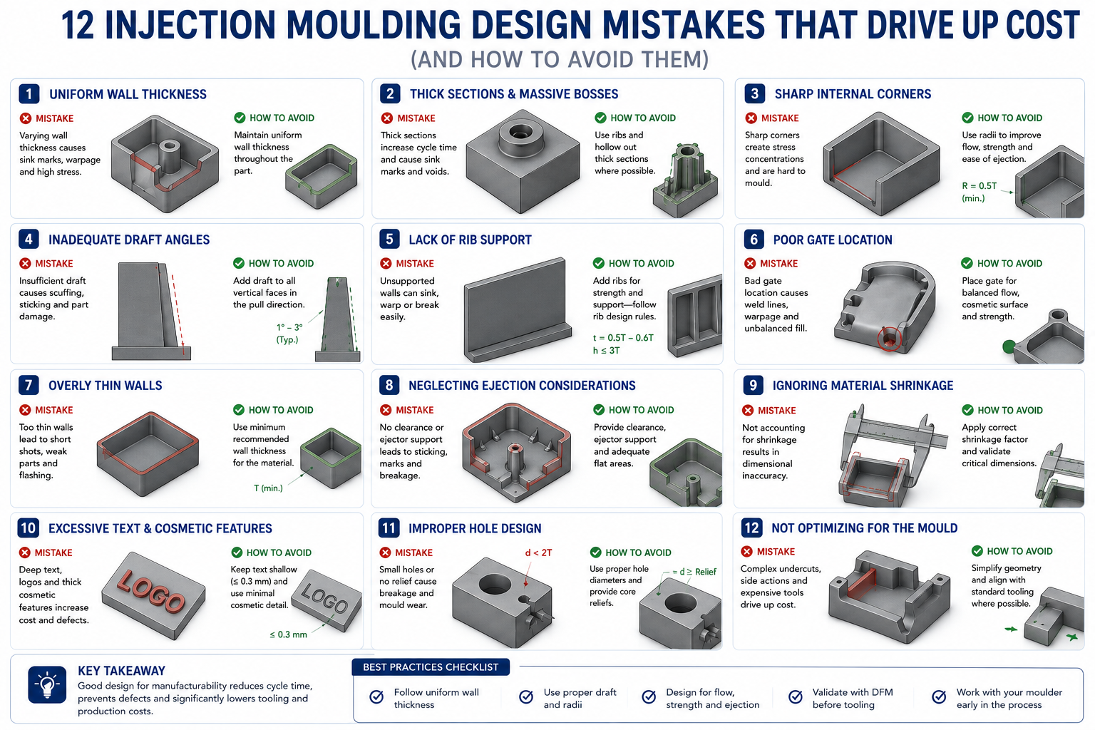
The 12 Most Costly Injection Molding Design Mistakes
Each mistake below is a CAD decision with direct consequences at the tool shop, on the injection press, or in the quality inspection booth. All are avoidable at the design stage.
| # | Mistake | Root Cause | Typical Cost Impact | Fix |
|---|---|---|---|---|
| 1 | Non-uniform wall thickness | Hollowing a solid CAD model without checking resulting variation | Sink marks, warping, longer cycle time; scrap 10-30% on first shots | Keep variation within 10-15% of nominal throughout |
| 2 | Insufficient draft angle | Draft added as an afterthought, not designed in | Part sticks; drag marks; ejector pin stress and tool damage | 1-2° minimum per side; 3-5° for textured surfaces |
| 3 | Sharp internal corners | Structural intent transferred without adaptation | Stress concentration, field failures, mould wear, fill problems | 0.5x wall thickness radius minimum; 0.75-1.0x preferred |
| 4 | Undercuts without planning | Feature designed without checking mould release direction | Slides/lifters add 20-50% tooling cost and lead time | Eliminate by redesign; budget for side actions early if unavoidable |
| 5 | Boss wall too close to nominal | Boss over-built for strength without the 60% rule | Visible sink marks opposite the boss on cosmetic face | Boss wall at 60% of adjacent wall; add gusset rib |
| 6 | Rib thickness causing sink marks | Ribs built at 75-100% of wall for structural confidence | Sink marks wherever a rib meets the wall | Rib base at 50-60% of adjacent wall; use multiple thin ribs |
| 7 | Gate location not considered | Gate left entirely to the mould maker | Weld lines in critical locations; fill imbalance, distortion | Agree gate location during design, not after |
| 8 | Weld lines in critical locations | Flow splits around a hole without consideration | Weld lines 10-50% weaker; field failures at these locations | Reposition gate or feature to move the weld line |
| 9 | Textured surfaces without extra draft | Texture specified without accounting for added draft need | Part tears on ejection; high surface reject rate | ~1° extra draft per 0.025mm of texture depth |
| 10 | Geometry requiring 3+ side actions | Complex features designed without evaluating tool complexity | Tooling cost 40-80% higher; longer lead time | Redesign to eliminate or consolidate side actions |
| 11 | Resin selected without process check | Resin chosen for mechanical properties, shrink rate ignored | Wrong shrinkage allowance; parts out of dimension | Confirm shrink rate for the resin and geometry before tooling |
| 12 | Tolerances tighter than process capability | Tolerance copied from a machined part design | Consistent inspection failures; sorting/rework cost | Typical range +/-0.1 to 0.25mm; tighter may not be achievable |
| The single most important habit: run a draft analysis before releasing any drawing. Most CAD packages colour-code every face relative to a specified pull direction, green for adequate draft, red for insufficient or negative draft. It takes two minutes and catches problems that cost thousands of dollars per face and weeks of delay once tooling is cut. |
Mistakes 1 and 2: Non-Uniform and Wrong Wall Thickness
Wall thickness is the single design parameter that most directly controls whether a moulded part looks acceptable, holds its shape, and produces at the assumed cycle time. Get it right and the mould fills evenly, cools uniformly, and ejects cleanly. Get it wrong and the problems cascade: thick sections cool slower than thin ones, so thin sections solidify first while the thick sections pull inward as they cool, creating visible sink marks and internal voids. Severe variation warps the entire part out of flat.
The target isn’t a specific thickness but a specific relationship between walls, following the process fundamentals documented in the Rosato Injection Molding Handbook: keep variation within roughly ten to fifteen percent of nominal throughout the part. A part with a 2.0mm nominal wall shouldn’t have regions thicker than 2.3mm or thinner than 1.7mm without a gradual transition. Where a thick section is unavoidable, taper into it over a distance of at least three times the thickness difference.
| Resin Family | Min Wall (mm) | Typical Nominal (mm) | Max Practical Wall (mm) | Key Notes |
|---|---|---|---|---|
| ABS | 1.2 | 1.5-3.0 | 4.5 | Versatile, forgiving flow; avoid exceeding 3mm without gas assist |
| Polycarbonate (PC) | 1.0 | 1.5-4.5 | 6.0 | Higher flow resistance; thick walls fill reliably but cycle time is long |
| PC/ABS blend | 1.2 | 1.5-3.5 | 5.0 | Popular for electronics enclosures; easier than pure PC |
| Nylon (PA6, PA66) | 0.8 | 1.5-3.0 | 4.0 | Absorbs moisture; design to nominal dry dimension |
| Polypropylene (PP) | 0.8 | 1.5-3.0 | 3.5 | High shrinkage (1.5-2.0%); excellent for living hinges |
| Acetal/Delrin (POM) | 0.8 | 1.5-3.0 | 3.0 | Excellent dimensional stability; good for precision gears |
| PEEK | 0.5 | 1.0-2.5 | 3.5 | Very high processing temperature; expensive resin and process |
| HDPE | 1.0 | 2.0-4.0 | 6.0 | High shrinkage; waxy surface complicates bonding and painting |
| PETG | 0.8 | 1.5-3.0 | 4.0 | Good clarity; lower impact resistance than PC |
| Liquid Silicone Rubber | 0.3 | 0.6-2.5 | 6.0 | Two-component thermoset; excellent for seals, soft-touch grips |
How the Solidification Sequence Governs Sink Marks
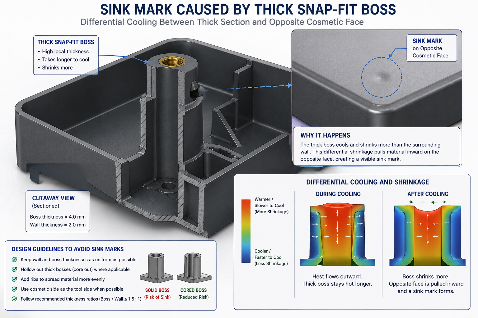
The mould is cold. The injected plastic is hot. Thin sections next to the cool steel lose heat quickly and solidify into a rigid skin. Thick sections take longer. As a thick section keeps cooling and shrinking after its skin has solidified, the still-soft interior gets pulled inward, and since the far skin is already rigid, the only surface that can move is the opposite face of the thin section adjacent to the thick one. That face dimples inward, producing the sink mark that appears on the cosmetic surface directly opposite the rib or boss.
This is why rib and boss thickness rules are expressed as ratios to the adjacent wall, not absolute values. A 1.5mm rib base next to a 3mm wall, at fifty percent, follows the rule. The same 1.5mm base next to a 1.0mm wall, at one hundred fifty percent, violates it by creating exactly the local thickness excess the rule exists to avoid. Track the ratio, not the dimension alone.
Mistake 2: No Draft Angle on Vertical Walls
When a mould opens, the part has to slide off the core without the walls dragging against the steel. Without draft, the part grips the core tightly as it cools and shrinks onto it, forcing the ejector pins to push it off. The result is drag marks, distortion from uneven ejector loading, and in the worst case a part that sticks entirely, destroying surface finish and risking broken ejector pins.
Draft doesn’t need to be large. On a smooth surface, one degree per side is typically adequate for clean ejection. The fix is applying the right taper before the drawing goes to the mould maker, since draft affects tool steel geometry, parting line position, and ejection layout. Asking for draft after the cavity and core are already machined means re-machining steel already cut to size, expensive and sometimes impossible without scrapping the insert.
Textured Surfaces Need More Draft Than You’d Expect
A smooth surface with one degree of draft ejects cleanly. The same surface with a leather-grain texture and the same one degree won’t. Texture creates physical interlocking with the tool steel, so the part has to tear away rather than slide cleanly, damaging the texture. The standard rule of thumb is one degree of additional draft for every 0.025mm of texture depth, so a leather grain at 0.075mm needs three additional degrees, four degrees total minimum. A heavy texture at 0.150mm needs six additional degrees beyond base draft.
Mistakes 4 and 10: Undercuts and Side Actions
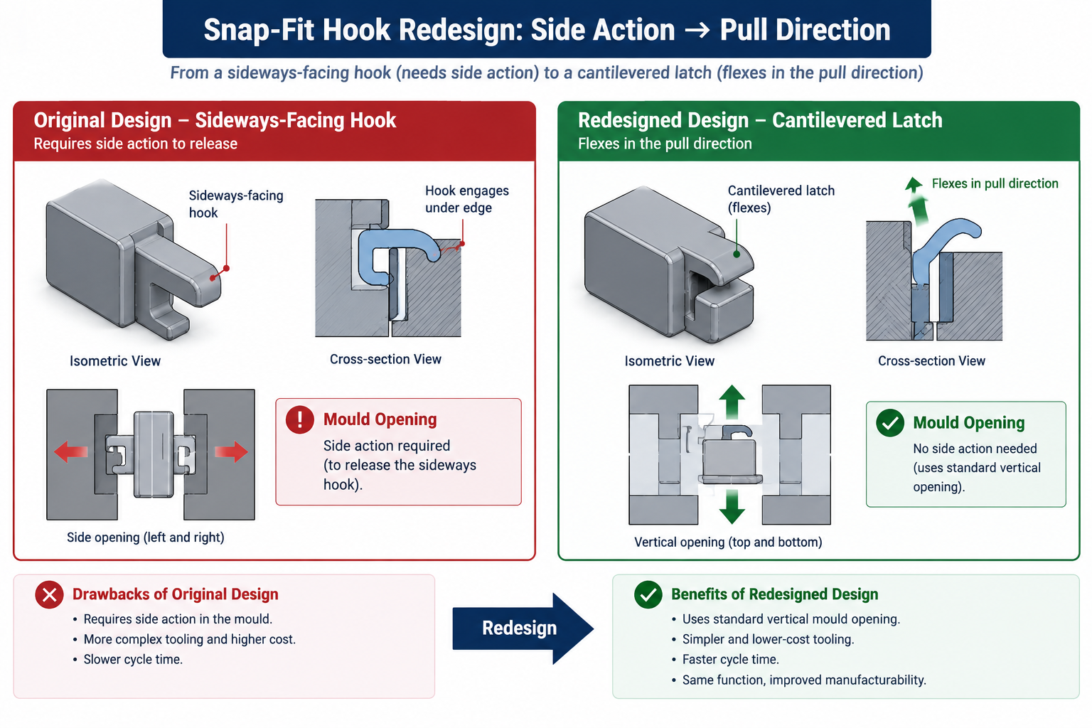
An undercut is any feature preventing the part from being pulled straight out of the mould in the opening direction. Sideways-facing snap-fit hooks, holes on vertical walls, internal threads, wrap-around lips: all trap the part if the mould tries to open in a straight line. The solutions, slides, lifters, collapsible cores, are proven mechanisms used on millions of parts every year, but each adds cost, tool complexity, lead time, and ongoing maintenance considerations.
| Undercut Type | Tooling Solution | Cost Premium | Lead Time Impact | When to Accept vs. Redesign |
|---|---|---|---|---|
| External undercut (lip, sideways hook) | Side action (slide) | +20-35% tooling cost | +2-4 weeks | Accept if function is genuinely required; redesign to a hinged snap if possible |
| Internal undercut (thread, groove) | Internal lifter or collapsible core | +25-50% tooling cost | +3-6 weeks | Consider a threaded insert or two-piece design before committing |
| Shallow undercut, flexible material | Forced ejection (stripped over) | No premium | No impact | Accept if material flexes without tearing; typically under 0.5mm depth |
| Through-hole perpendicular to draw | Simple core pin | No premium | No impact | Always prefer over a blind hole where function allows |
| Hole on a side face (parallel to parting line) | Side core or split cavity | +10-20% tooling cost | +1-2 weeks | Accept when genuinely functional; verify parting line flash is acceptable |
How to Spot an Undercut Before the Drawing Goes Out
Set the pull direction in CAD and run draft analysis, which flags any negative-draft faces as potential undercuts. Sideways-facing faces relative to the pull direction are the most common source. A hole drilled through a vertical wall is a simple example: the core pin forming it runs perpendicular to the pull direction, trapping the surrounding steel unless a slide is provided.
Before budgeting for a side action, ask whether the feature causing it can be moved or redesigned. A sideways-facing snap hook can sometimes become a cantilevered latch that flexes in the pull direction, eliminating the undercut entirely. A hole on a vertical side wall can sometimes move to the parting surface, becoming a through-feature both halves of the tool form, needing no slide. These redesigns take minutes in CAD and save thousands in tooling cost.
Mistakes 7 and 8: Gate Location and Weld Lines
Gate location, where plastic enters the cavity, is one of the most consequential decisions in mould design, and one many designers leave entirely to the mould maker without guidance. That’s a missed opportunity. The design engineer knows which surfaces are cosmetic and cannot show a gate mark, and which features are structural and shouldn’t have weld lines running through them. The mould maker knows injection molding but doesn’t know which is which unless told. Gate location should be a conversation during design, not a surprise after the tool is built.
| Gate Type | Appearance | Weld Line Risk | Best For | Avoid When |
|---|---|---|---|---|
| Edge gate (tab) | Visible stub on parting line; needs degating | Low for simple parts; higher with multiple features | Simple flat parts, prototype tooling | Cosmetic surfaces on the parting line edge |
| Submarine (tunnel) gate | Auto-degated, small dimple below parting surface | Moderate | High-volume production, labour savings | Brittle resins that crack at the shear point |
| Pin point gate (3-plate) | Small round mark, auto-degated | Low; positionable away from critical areas | Multi-cavity tools, specific face gating | Large parts with high flow resistance |
| Hot tip gate | Small vestige only; no cold runner waste | Low, precisely controlled | High-volume, multi-cavity balanced filling | Low-volume runs; heat-sensitive resins |
| Fan gate | Wide, shallow, visible at parting edge | Very low; distributes flow evenly | Flat sheet-like parts, optical components | Cosmetic surfaces along the gated edge |
| Valve gate (hot runner) | No or minimal vestige | Low, controllable via timing | Cosmetic surfaces; sequential fill control | High complexity/cost; not for low-volume tools |
Weld Lines: Where They Come From and Why They Matter
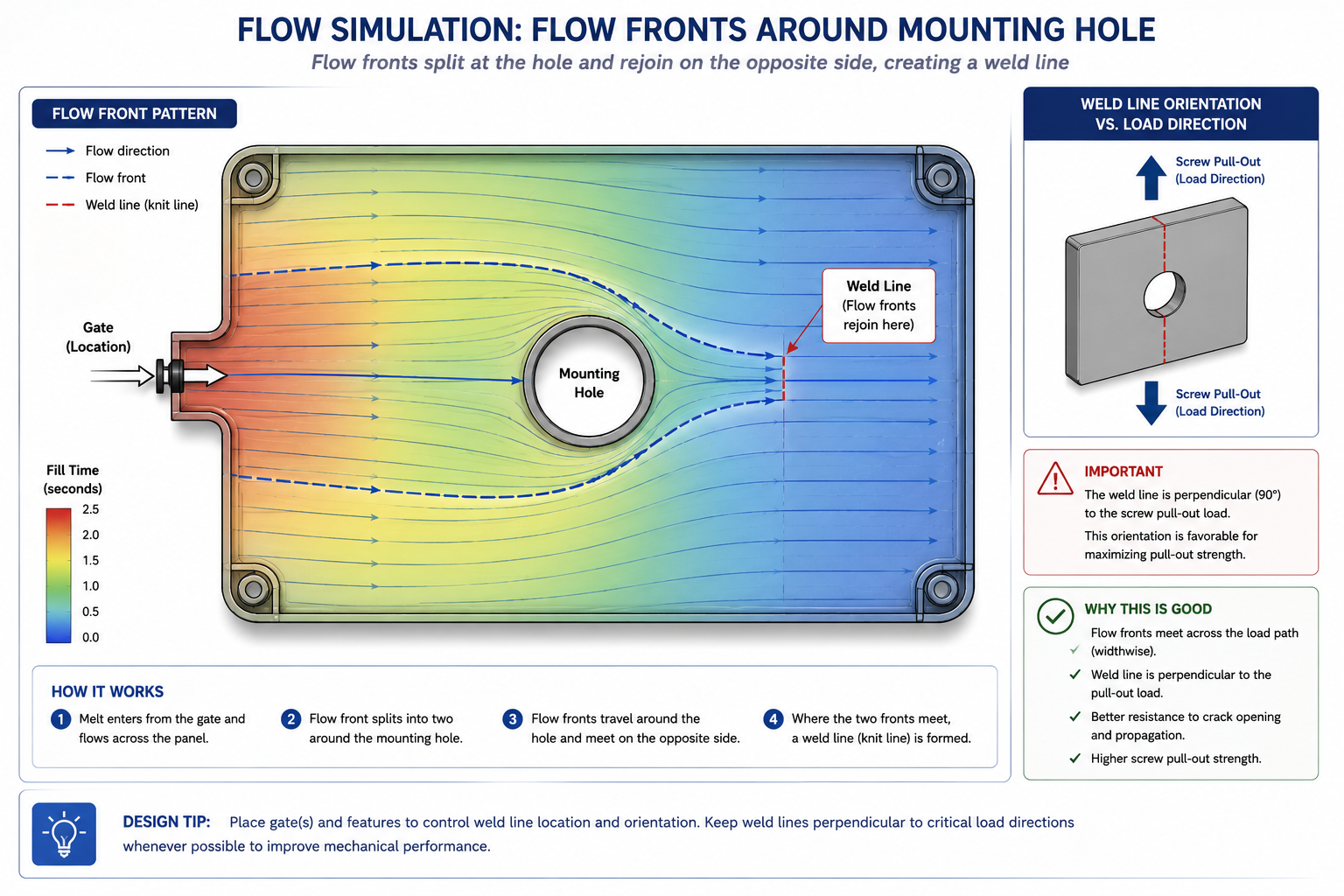
A weld line forms wherever two flow fronts of molten plastic meet and fuse during filling. Every hole in a moulded part creates one downstream of it, since flow splits around the hole and rejoins on the far side. A part with four holes has at least four potential weld lines. Their location relative to structural loads and cosmetic surfaces is set by gate placement and flow path geometry, and moving the gate can move the weld lines without changing the part’s functional geometry.
Weld lines are mechanically weaker than the surrounding material because the two flow fronts have cooled slightly by the time they meet, and molecular chains and glass fibres (in filled resins) orient parallel to the weld line rather than across it. In unfilled amorphous plastics like ABS, strength reduction might be ten to twenty percent. In glass-filled semi-crystalline plastics like PA66 GF30, it can reach fifty percent, since the fibres that carry load in the base material leave the weld line essentially unreinforced. A weld line running through the root of a snap-fit latch or a screw hole edge is designed to fail there under repeated loading.
Mistakes 5 and 6: Bosses and Ribs That Cause Sink Marks
Bosses and ribs account for more sink mark problems than any other feature type, since both need local material thickness to function, and local thickness excess is exactly what causes sink marks. The rules are simple and widely published, but frequently violated by an instinct to make the boss wall thicker for strength or the rib taller and thicker for stiffness, both of which push directly toward the sink mark the rule exists to prevent.
The Boss Wall Rule
A screw boss needs enough wall thickness to resist hoop stress from screw insertion without cracking, and enough depth for adequate thread engagement. That functional wall thickness is approximately sixty percent of the adjacent nominal wall, providing adequate strength for normal self-tapping screw torque without visible sink marks.
When a designer increases the boss wall beyond sixty to seventy-five percent, the local thickness increase becomes large enough that differential cooling pulls the opposite face inward, producing a visible circular sink mark on the cosmetic surface. The fix once the mould already exists is either texturing the cosmetic surface to hide it or reworking the boss geometry in the tool, both costing money the sixty percent rule would have avoided. Adding a gusset rib from the boss to the nearest structural wall satisfies both the structural requirement and the sink mark rule simultaneously.
The Rib Thickness Rule
Ribs add stiffness without the wall thickness that would increase cooling time, weight, and sink mark risk. But a rib is itself a local thickness increase where it meets the wall, and if the rib base is too thick relative to the wall, it creates exactly the local thick section it was supposed to avoid. The rule: rib base should be fifty to sixty percent of the adjacent nominal wall. A 2mm nominal wall should have ribs no more than 1.0 to 1.2mm thick at the base.
When a designer specifies a rib at seventy-five or a hundred percent of wall thickness for extra structural confidence, the rib creates a local thickness the molding process faithfully converts into a sink mark opposite the rib junction. The fix isn’t a thicker rib, it’s more ribs, each following the fifty to sixty percent rule, distributed over the area needing stiffness. Multiple thin ribs outperform a single thick rib in structural efficiency, sink mark avoidance, and material usage.
Worked Examples
The consumer electronics housing: A mould maker’s pre-tooling review flagged three issues: a 5mm wall behind a snap-fit boss where the designer had added material for strength, a USB port opening on a side wall creating an internal undercut requiring a lifter, and a textured grip area specified with only one degree of draft against a 0.08mm texture depth.
The boss wall was reduced to 1.8mm, sixty percent of the 3mm nominal wall adjacent to it, with a gusset rib added to the nearest internal rib for the structural connection the extra material had been trying to provide. The USB port was relocated so its axis ran parallel to the mould pull direction, converting the undercut into a simple through-feature formed by a core pin, a 4mm position shift the product team accepted after an ergonomics check. The textured faces were redesigned with four degrees of draft, one base plus three for the texture depth.
The tooling was cut to the revised design without any of the three original issues. First shots showed no sink marks, no ejection damage, clean texture release, and matched the original quote. The two days of CAD work prevented what the mould maker estimated would have been a three-to-four-week rework programme costing thirty-five percent of the original tool budget.
The automotive interior component with weld line failures: A trim panel with two mounting holes was gated at the centre of the top edge, sending flow symmetrically toward mounting holes on either side. The flow fronts that split around each hole rejoined directly in line with the screw thread pull-out direction, the axis of highest stress in service. The panel was failing at forty percent of target pull-out force, with clean, planar failure surfaces, the classic morphology of a weld line fracture.
The resin was PA66 GF30, where weld line strength can drop to forty to fifty percent of base material strength. Moving the gate to one end of the panel sent a single flow front across it, still splitting around each hole but rejoining at angles roughly perpendicular to the panel face rather than aligned with the pull-out direction, and the shorter flow path to the far hole reduced the temperature drop before rejoining, improving fusion. Pull-out results improved to ninety-two percent of target, meeting spec, from a runner-only tool modification completed in two days with no cavity or core rework needed.
Frequently Asked Questions
What is the most common injection molding design mistake? Non-uniform wall thickness, and the one with the most visible consequences, since the sink marks it causes show up on cosmetic surfaces where every customer and quality inspector can see them. It’s also the mistake most common among engineers experienced with machined parts, where a thick section just takes longer to cut rather than cooling differently and producing surface defects.
How much draft angle do injection moulded parts actually need? One degree per side is the practical minimum for smooth surfaces, with two degrees giving comfortable margin. For textured surfaces, add roughly one additional degree per 0.025mm of texture depth beyond the base one degree. A light orange-peel texture at 0.025mm needs about two degrees total; a leather grain at 0.075mm needs about four; a heavy tactile texture at 0.15mm may need six or more.
Can I get away without draft angle if I use a good ejection system? Not reliably. Stripper plates, air blast, and heavy ejector pin layouts can push a part off a zero-draft surface, but that force transmits through the part, distorting it or leaving ejector pin marks. For production tooling where appearance and consistency matter, no ejection system reliably substitutes for adequate draft.
What is a weld line and does it always need to be avoided? A weld line is the seam where two flow fronts of molten plastic meet and fuse during filling. They form wherever flow splits and rejoins, downstream of every hole, protrusion, and obstacle, and can’t be eliminated from parts with multiple flow-splitting features. What matters is location and load: a weld line on a hidden, non-structural surface is typically fine, while one through a snap-fit latch root or a mounting boss in glass-filled nylon is a real structural risk.
How tight a tolerance can injection molding actually hold? Typical production parts hold +/- 0.1 to 0.25mm on linear dimensions. Down to +/- 0.05mm is achievable on small parts with controlled process conditions, high-quality tooling, and predictable-shrinkage resins, but needs careful monitoring. Tighter than +/- 0.05mm generally requires secondary operations like machining on specific surfaces. Semi-crystalline resins (nylon, PP) shrink more and less predictably than amorphous resins (ABS, PC).
When should I use a hot runner instead of a cold runner? Hot runners eliminate the cold runner that would otherwise be ejected and scrapped or recycled each cycle, saving material cost and allowing faster cycle times. The manifold itself adds two thousand to twenty thousand dollars to tooling cost depending on complexity, recovered through material and cycle time savings over the production run. This makes economic sense above roughly fifty thousand parts per year for moderate-cost resins, lower for expensive engineering resins like PEEK, and doesn’t make sense for prototype or low-volume tools.
Key Takeaways
The twelve mistakes in this article aren’t exotic edge cases. They’re the items that generate the most tool rework, the most first-shot rejection, and the most programme delays across consumer electronics, automotive, medical, and industrial moulded products. Nearly all of them are avoidable at the CAD stage by an engineer who knows what to look for, and free to fix while the part is still on screen.
The housing story at the start of this article wasn’t a failure of engineering skill. It was a failure of knowledge applied at the right time. Every one of the three problems the mould maker called about has a straightforward CAD fix that takes minutes. The same fix in tooling takes days to weeks and costs real money. Run the draft analysis on every moulded part before the drawing is released. Check every boss and rib against the sixty and fifty percent wall ratio rules.
Walk the pull direction and flag every trapped face. Agree gate location with the mould maker before the tool is designed, not after. These habits are inexpensive in CAD and genuinely expensive to substitute for afterward.