| 86% of US engineering companies use ASME Y14.5 as their GD&T standard (Krulikowski survey, 133 respondents across 27 countries) 56% of non-US international companies also use ASME Y14.5, making it the most-used GD&T standard globally despite ISO GPS being the international standard 100+ individual modular standards in the ISO GPS family, compared to approximately 17 documents in the ASME Y14 series R2024 ASME Y14.5-2018 reaffirmed in 2024, confirming it remains the current ASME GD&T standard. No new revision is in force as of 2026. |
Introduction:
A machined shaft is designed in the United States under ASME Y14.5. The purchase order goes to a precision machinist in Germany who works exclusively to DIN EN ISO standards. The drawing arrives. The machinist reads the cylindricity tolerance as independently controlled, as ISO 8015 requires, and machines the shaft to those standards. The shaft arrives in the US. Inspection rejects it because under ASME’s envelope principle, the size tolerance was supposed to control the cylindricity automatically, and the part’s form errors fall outside what the ASME-reading inspector considers acceptable.
Nobody did anything wrong. The drawing was correct. The machinist was correct. The inspector was correct. The problem was that the drawing did not state which engineering drawing standard governed its GD&T, and the two parties operated under different default assumptions about what the same symbols and tolerance values meant.
This guide explains what ASME, ISO, and DIN drawing standards are, how they differ technically and philosophically, which industries and geographies use which, and what the specific conflicts are between standards that cause parts to be made or inspected incorrectly when engineers do not know which standard applies.
| Quick answer: ASME Y14.5 is the US standard for GD&T and engineering drawings, using third-angle projection and the envelope principle by default. ISO GPS (ISO 1101 and related standards) is the international standard, using first-angle projection and the independency principle. DIN standards are German national standards that have largely been harmonised with ISO since the 1990s and are now cited as DIN EN ISO in most cases. All three must be explicitly stated in the drawing title block because mixing them without notation causes misinterpretation of tolerances and views. |
ASME, ISO, and DIN: What Each Standard System Actually Is
ASME: The American Engineering Drawing Language
ASME stands for the American Society of Mechanical Engineers, a non-profit professional organisation founded in 1880. Its Y14 series of standards defines how engineering drawings are produced and interpreted in the United States. The most important of these is ASME Y14.5, which defines GD&T: the symbolic language for communicating dimensional requirements and tolerances.
ASME Y14.5 can trace its roots to MIL-STD-8, a US military standard from 1949. It was the wartime need for interchangeable parts produced at multiple facilities that drove the early development of formalised geometric tolerancing. The standard has been revised approximately every decade since the 1960s. The current version is ASME Y14.5-2018, reaffirmed in 2024 (designated R2024), confirming it remains in force. No newer revision is in effect as of 2026.
The 2018 edition made two changes that every engineer working to ASME standards should know: it deprecated the concentricity and symmetry symbols, replacing them with positional or profile controls, and it explicitly incorporated Model-Based Definition (MBD), recognising that tolerances are increasingly embedded in 3D models rather than printed on 2D drawings.
ISO GPS: The International Drawing Language
ISO is the International Organization for Standardization, founded in 1947. Its ISO GPS system (Geometrical Product Specifications) is the international framework for engineering drawing standards, covering everything from line types (ISO 128) to surface texture (ISO 1302) to the full GD&T system (ISO 1101, ISO 8015, and over 100 related standards).
Unlike ASME’s relatively consolidated Y14 series of around 17 documents, the ISO GPS system is modular and composed of more than 100 interrelated standards, each covering a narrow, specific aspect of geometric specification. ISO 1101 covers tolerancing symbols. ISO 8015 defines the fundamental rules. ISO 5459 covers datum references. ISO 14638 defines the masterplan for the GPS system. This modularity is both a strength, each standard can be updated independently, and a challenge, because understanding the full system requires familiarity with multiple documents.
ISO GPS is the default standard in Europe, increasingly adopted in Asia, and the required standard for international supply chains that cross multiple regulatory jurisdictions. Its first-angle projection convention and independency principle for tolerancing represent fundamentally different default assumptions from ASME.
DIN: The German National Standard
DIN stands for Deutsches Institut fur Normung, the German Institute for Standardization, founded in 1917. DIN standards for engineering drawings have been through significant harmonisation with ISO since the 1990s as part of European standardisation efforts. The consequence is that most current DIN engineering drawing standards are designated DIN EN ISO, meaning they are the German national adoption of a European (EN) adoption of an International (ISO) standard.
The practical meaning: DIN EN ISO 1101 is the same standard as ISO 1101 in technical content. DIN EN ISO 2768 is the same as ISO 2768. When a German supplier cites DIN EN ISO standards, they are working to the same technical requirements as any other ISO GPS user. The DIN-specific designation indicates the standard has been formally adopted as a German national standard, which carries regulatory significance in some procurement contexts.
Where DIN remains genuinely distinct is in standards that have not been harmonised, such as DIN 7168 (German general tolerances, which differs from ISO 2768 in some tolerance classes), older DIN standards that remain in use in specific industries, and VDA (Verband der Automobilindustrie) supplementary standards for German automotive supply chains that have no direct ISO equivalent.
| Attribute | ASME (Y14 series) | ISO (GPS system) | DIN (German standard) |
| Governing body | American Society of Mechanical Engineers | International Organization for Standardization | Deutsches Institut fur Normung (German Institute for Standardization) |
| Primary geography | USA, Canada, parts of Asia | Europe, Asia, global baseline | Germany, Austria, German-speaking markets |
| GD&T standard | ASME Y14.5-2018 (R2024) | ISO 1101, ISO 8015, 100+ GPS standards | DIN ISO 1101 (mirrors ISO GPS) |
| Projection method | Third-angle projection (ANSI) | First-angle projection (ISO) | First-angle projection (ISO-aligned) |
| Line standards | ASME Y14.2 | ISO 128 | DIN ISO 128 |
| Title block standard | ASME Y14.1 | ISO 7200 | DIN 6771 |
| Tolerance philosophy | Envelope principle (Taylor principle) | Independency principle (ISO 8015) | Independency principle (ISO-aligned) |
| Default for dimensions | All dims controlled by size limits | Form error independent of size | Form error independent of size |
| Standards structure | ~17 documents in Y14 series | 100+ modular GPS standards | Aligned to ISO, with German national supplements |
| Industry dominance | Aerospace, defence, US automotive | European mfg, pharma, global supply | German automotive (VDA), machinery, industrial |
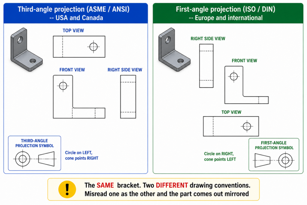
Third-Angle vs First-Angle Projection: The Most Visible Difference
This is the difference that causes the most obvious manufacturing errors when it is not checked. The projection method determines where each view sits on the drawing sheet relative to the front view, and getting it wrong means reading a right side view where a left side view should be, and vice versa.
| Aspect | Third-angle projection (ASME / ANSI) | First-angle projection (ISO / DIN) |
| Where views sit | View placed on the side you look from. Right side view sits to the right of front view. | View placed on the opposite side. Right side view sits to the LEFT of front view. |
| Top view position | Top view sits ABOVE the front view | Top view sits BELOW the front view |
| Identification symbol | Circle on left, cone pointing right | Circle on right, cone pointing left |
| Dominant standard | USA, Canada, Australia (some use) | Europe, Asia, rest of world |
| Risk of confusion | Reading first-angle as third-angle produces mirrored or inverted parts | Same risk applies in reverse for non-European readers |
| Where stated | Always in the title block | Always in the title block |
| Critical check | Confirm before reading any drawing from an unfamiliar source | Never assume. Always check the projection symbol in the title block first. |
The projection symbol in the title block is small and easy to overlook. It is also the single most important piece of information on the drawing for anyone who has not worked with both systems. An engineer trained exclusively in ASME drawings, reading a European supplier’s first-angle drawing without checking the symbol, will consistently misidentify which side of the part each view shows.
| The manufacturing consequence of projection confusion: A bracket designed with a mounting boss on the right side, read from a first-angle drawing by an engineer expecting third-angle, will be interpreted as having the boss on the left side. The machinist machines what the drawing appears to show. The part is wrong. By the time it is discovered, the setup, material, and machining time are wasted. The root cause is not the drawing. It is failing to check the projection symbol before reading the views. |
Envelope vs Independency: The Most Important Technical Difference
This is the difference that causes the most subtle and expensive manufacturing problems when standards are mixed, because the same tolerance value means something different depending on which principle applies. A 25mm shaft toleranced at plus or minus 0.1mm under ASME and the same shaft under ISO are not the same specification, even though the numbers are identical.
| Aspect | Envelope Principle (ASME Y14.5) | Independency Principle (ISO 8015 / DIN) |
| What it means | The size tolerance automatically controls form. A 25mm +/-0.1mm cylinder may not exceed a perfect 25.1mm envelope at any cross-section. | Size and form are independent. A 25mm +/-0.1mm cylinder may be anywhere between 24.9mm and 25.1mm at any cross-section, but form errors must be separately controlled. |
| Who controls form errors | The size limits do this automatically for ASME drawings without extra symbols | Form errors (straightness, cylindricity, flatness) must be explicitly called out with GD&T symbols |
| Effect on design | Fewer symbols needed for simple prismatic features | More symbols required to fully constrain form, but intent is more explicit |
| Effect on inspection | Envelope gauge checks form and size simultaneously | Form and size inspected separately unless combined control is explicitly stated |
| Which standard applies | ASME Y14.5 (default, unless E modifier reverses it) | ISO 8015 (default for ISO drawings). ASME can invoke ISO 8015 using the E modifier. |
| Risk of misinterpretation | An ISO-trained inspector may not apply the envelope check on an ASME drawing | An ASME-trained inspector may assume form is controlled when it is not on an ISO drawing |
A Practical Example of the Difference
An ASME drawing specifies a shaft diameter of 25.00mm plus or minus 0.10mm. Under the envelope principle, this means the shaft must pass through a perfect 25.10mm ring gauge (the maximum material boundary) and must be no smaller than 24.90mm anywhere. The ring gauge check automatically verifies that the shaft is straight and circular within the size tolerance. No separate cylindricity callout is needed.
The same shaft on an ISO GPS drawing with the same diameter tolerance of 25.00mm plus or minus 0.10mm operates under the independency principle. The shaft may be anywhere between 24.90mm and 25.10mm at any cross-section, but the form errors (how straight and circular it is) are not controlled by the size tolerance. If the shaft must also be straight within a certain tolerance, a separate straightness callout is required. If cylindricity must be controlled, a cylindricity callout is required.
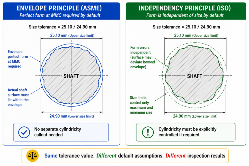
| The practical result: a shaft manufactured to the ASME specification may have better form control than required by ISO, or an ISO shaft may have worse form than an ASME-trained inspector expects. Both are correct for their respective standards. Neither is wrong. But if an inspector trained in ASME applies the envelope principle to an ISO-drawn part, they may accept or reject parts incorrectly. |
GD&T Symbol Differences Between ASME and ISO: Where Conflicts Actually Live
Most are identical between ASME Y14.5 and ISO 1101. The flatness symbol, the straightness symbol, the angularity symbol, the position symbol: all use the same geometric shapes with the same meaning. This convergence has been deliberate and sustained over decades of parallel standard development. The conflicts that exist are important precisely because they are not obvious from a visual scan of the symbols.
| Feature / Symbol | ASME Y14.5 | ISO GPS (ISO 1101) | Practical consequence of mixing |
| Flatness | Flatness symbol (parallelogram) | Same symbol, different default scope | Both use same symbol but ISO requires explicit callout where ASME uses envelope rule |
| Cylindricity | Explicit callout required | Explicit callout required | No difference in symbol, significant difference in when it is needed |
| Position (Location) | True position symbol, bidirectional | Same symbol, ISO may use differently | Always verify datum scheme matches between supplier and buyer |
| Datum feature symbol | Filled triangle on leader | Same but triangle placement differs | Datum A may point to different surface if convention not stated |
| Angularity | Angularity symbol | Same symbol | No symbol conflict, same interpretation |
| Concentricity | In ASME Y14.5-2018: deprecated | Still used in ISO | Critical conflict: ASME has removed this symbol. ISO still uses it. |
| Symmetry | In ASME Y14.5-2018: deprecated | Still used in ISO | Critical conflict: same as concentricity situation above. |
| Runout | Circular and total runout | Circular and total runout | Same meaning, same symbols, no conflict |
| Projected tolerance zone | PTZ modifier in ASME | ISO uses P modifier differently | PTZ application differs between standards. State standard on drawing. |
| Surface texture (Ra) | ASME B46.1 | ISO 1302 / ISO 4287 | Both use Ra value but measurement method and filtering can differ |
The Concentricity and Symmetry Deprecation: A Live Conflict
The most significant current conflict between ASME and ISO GD&T symbol sets is the deprecation of concentricity and symmetry in ASME Y14.5-2018. These symbols remain in active use in ISO GPS drawings and are taught in ISO-based GD&T training globally.
In ASME Y14.5-2018, both were removed and replaced by position or profile of a surface controls, which Subcommittee 5 argued were more precisely defined and more readily inspectable. The argument has merit: concentricity as defined required deriving a median point from every diametrically opposed pair of points on the surface, which is mathematically rigorous but metrologically challenging.
The practical consequence for engineers: if you receive a drawing with a concentricity symbol and you are working to ASME Y14.5-2018, the symbol is formally undefined in your standard. If the drawing states ISO 1101 as its reference, the symbol is valid and means what it says. If the drawing states nothing, you have no way of knowing which interpretation to apply without asking. This is exactly the situation the title block note requirement is intended to prevent.
Key Engineering Drawing Standards: Complete Reference Table
The table below provides a quick reference to the most important engineering drawing standards across all three systems, covering what each standard covers and its current status.
| Standard | Body | Year / Status | What it covers |
| ASME Y14.5 | ASME | 2018 (R2024) | Geometric dimensioning and tolerancing: all GD&T symbols, datum references, tolerance zones |
| ASME Y14.1 | ASME | Current | Drawing sheet sizes, title block format, and drawing format requirements |
| ASME Y14.2 | ASME | Current | Line conventions and lettering for engineering drawings |
| ASME Y14.41 | ASME | Current | Digital product definition data practices (MBD, 3D annotation) |
| ASME Y14.100 | ASME | Current | Engineering drawing practices: completeness, approval, revision control |
| ISO 128 | ISO | ISO 128-1:2020 | General principles for technical drawings: line types, projections, views |
| ISO 1101 | ISO | ISO 1101:2017 | Geometrical tolerancing: symbols, definitions, tolerance zones (ISO GPS core standard) |
| ISO 8015 | ISO | ISO 8015:2011 | Fundamentals of tolerancing: independency principle, ISO default rules |
| ISO 2768 | ISO | ISO 2768-1/2 | General tolerances for linear and angular dimensions (medium m, fine f classes) |
| ISO 7200 | ISO | ISO 7200:2004 | Title block format and data fields for technical drawings |
| ISO 1302 | ISO | ISO 1302:2002 | Surface texture indication on technical drawings (Ra, Rz symbols) |
| ISO 10628 | ISO | ISO 10628-2:2012 | Symbols for process plant diagrams (P&IDs and flow diagrams) |
| DIN 6771 | DIN | Current | German title block standard, supplementary to ISO 7200 |
| DIN ISO 1101 | DIN | Mirrors ISO 1101 | German national adoption of ISO geometrical tolerancing standard |
| DIN 7168 | DIN | Current | German general tolerances for linear and angular dimensions (precedes ISO 2768) |
| DIN EN ISO 2768 | DIN | Current | German adoption of ISO 2768 general tolerances, often still cited as DIN 2768 |
| Practical rule for cross-border drawings: When creating a drawing that will be manufactured outside your home country, look up whether the standards you are referencing are recognised by your supplier’s standards system. Most ASME standards are not formally adopted in Europe. Most ISO standards are available in the USA but not universally taught or enforced. When in doubt, state all relevant standards explicitly in the general notes and confirm with the supplier’s quality team that they hold the referenced documents. |
General Tolerances: ISO 2768, DIN 7168, and the ASME Approach
General tolerances are the tolerances that apply to all undimensioned or untoleranced features on a drawing, defined by a single title block reference rather than individual callouts. They are one of the most frequently misunderstood elements of cross-standard drawing practice.
ISO 2768: The International General Tolerance Standard
ISO 2768 defines general tolerances for linear and angular dimensions in two parts. ISO 2768-1 covers linear dimensions and angles in four classes: fine (f), medium (m), coarse (c), and very coarse (v). ISO 2768-2 covers geometrical tolerances in three classes: H, K, and L. A drawing referencing ISO 2768-mK in its general notes is specifying medium-class linear tolerances and K-class geometrical tolerances for all features not individually dimensioned.
ISO 2768 medium (m) is the most commonly specified class for general machined parts and represents what most competent machine shops can hold in production without special process controls. Fine (f) requires tighter process discipline and is appropriate for precision assemblies. The class should be chosen to match the actual manufacturing process capability of the supplier, not to the tightest possible requirement.
DIN 7168 and DIN 2768: The German Predecessors
DIN 7168 is the German general tolerance standard that predates ISO 2768 and covers similar ground with some different tolerance class definitions. Many older German engineering drawings reference DIN 7168 rather than ISO 2768. The two are not identical in all tolerance class values, which means a drawing referencing DIN 7168 fine and a drawing referencing ISO 2768-f are not necessarily specifying the same tolerances on every feature.
DIN 2768 is frequently cited in engineering contexts but refers to the German national adoption of ISO 2768, technically designated DIN EN ISO 2768 in its current form. For practical purposes, DIN EN ISO 2768 and ISO 2768 are technically equivalent. DIN 7168 is the historically distinct German standard that should not be assumed equivalent to ISO 2768 without checking the specific tolerance values.
ASME and General Tolerances
ASME does not use ISO 2768. The ASME approach to general tolerances is different: ASME Y14.5 provides for general tolerance notes in the title block that define plus/minus values for specific dimension ranges, and ASME Y14.100 covers drawing practices including default tolerances. An ASME drawing with a title block note reading ‘3-place decimals: plus/minus 0.005 inch’ is applying a general tolerance, but under a completely different framework from ISO 2768.
An engineer moving from an ISO GPS environment to an ASME environment cannot assume that referencing ISO 2768 is meaningful on an ASME drawing. It is not part of the ASME drawing practice system. The general tolerances must be expressed using ASME-compatible notation.
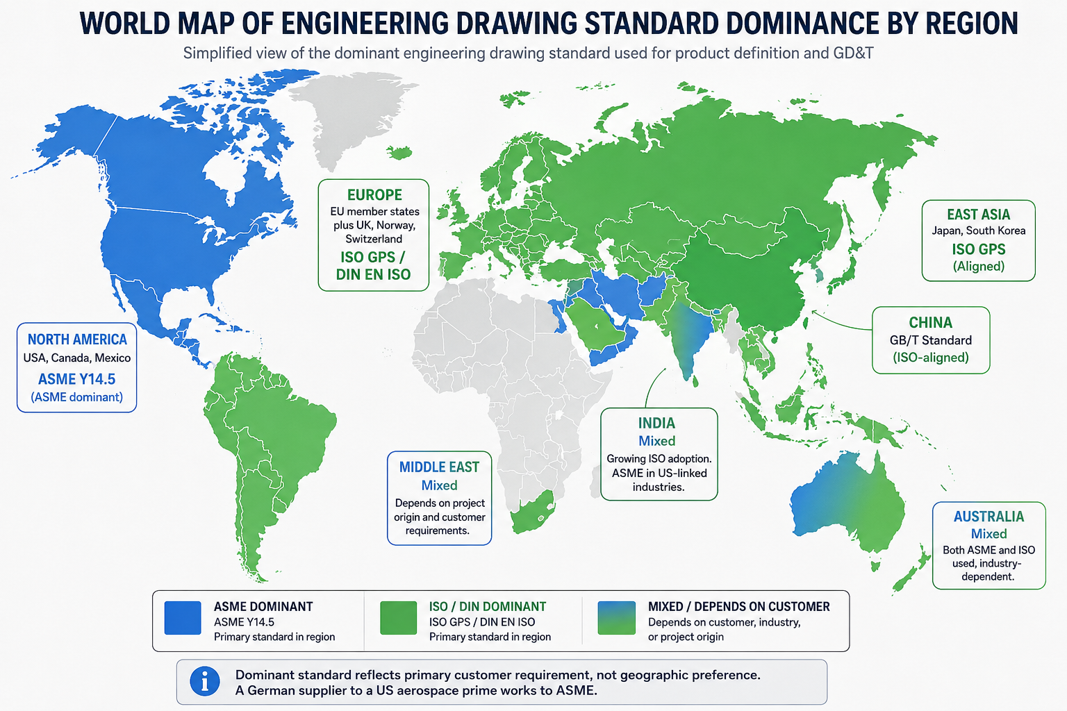
Which Industries Use Which Standards: The Real-World Map
Standard selection in most organisations is driven by customer requirements, regulatory obligations, and the geographic location of the primary manufacturing base, not by any abstract technical preference. Understanding which standards dominate which industries tells you immediately which standard to use for a given project.
| Industry | Dominant standard | Reason | Typical supplementary standards |
| US Aerospace and Defence | ASME Y14.5-2018 | MIL-STD heritage, US OEM requirement | AS9100, ASME Y14.100, ASME Y14.41 for MBD |
| European Aerospace | ISO GPS (EN 9100 aligned) | EU OEM and EASA regulatory chain | ISO 10135, ISO 1302, NADCAP quality reqs |
| German Automotive (VDA) | DIN / ISO GPS + VDA norms | VDA 2 quality and DIN tool standards | VDA 2, VDA 6.1, DIN 7168, DIN ISO 2768 |
| US Automotive (AIAG) | ASME Y14.5 + AIAG | Big-Three OEM supply chain standard | AIAG PPAP, MSA, FMEA documentation |
| Medical devices (FDA) | ASME or ISO by choice | FDA 21 CFR Part 820 references both | ISO 13485, FDA guidance on drawings |
| Pharmaceutical (EU GMP) | ISO GPS preferred | EU GMP and EMA regulatory alignment | EU GMP Annex 15, ISO 9001 |
| Industrial machinery | ISO / DIN (Europe) | EN machinery directive compliance | ISO 4156, DIN 7168 general tolerances |
| Consumer electronics | ISO or ASME by region | Depends on where manufactured / sold | IPC standards for PCB, ISO 2768 general |
| Oil and gas (ASME PCC) | ASME B31, API standards | ASME pressure vessel and piping codes | API 6A, ASME B16.5, ASME VIII Div 1 |
The US Dominance of ASME in a Global Market
The survey data from GD&T educator Alex Krulikowski, with 133 respondents from 27 countries, found that 86 percent of US participants use ASME Y14.5 and 56 percent of international participants also use ASME Y14.5. These numbers reflect the historical dominance of US manufacturing, defence, and aerospace programs in setting supply chain documentation standards globally. A German tier-two supplier working for a US aerospace prime must produce ASME-compliant drawings for that program regardless of what their domestic German customers require.
The result is that many engineering teams outside the US maintain dual capability: ISO GPS for domestic and European customers, ASME Y14.5 for US and US-primed programs. This is manageable but requires explicit drawing management discipline, because the same part designed to two different standards requires two different drawings, and mixing elements from each into a single drawing creates the type of ambiguity that the shaft example at the beginning of this guide illustrates.

The Title Block: Where the Standard Is Declared and Why It Must Be
Every engineering drawing has a title block in the bottom-right corner. That title block is the drawing’s identity document, and it is also where the applicable drawing standard must be stated. Without an explicit standard reference in the title block or general notes, any GD&T on the drawing is ambiguous.
What the Title Block Must State for Standard Compliance
- Applicable GD&T standard: ‘Geometric tolerancing per ASME Y14.5-2018’ or ‘Geometric tolerancing per ISO 1101:2017’ — state the standard and the year of issue
- General tolerance reference: ‘Unless otherwise specified, general tolerances to ISO 2768-mK’ or the equivalent ASME general tolerance note
- Projection method: The first-angle or third-angle projection symbol — this should be graphic, not text, so it is recognisable internationally
- Surface texture standard: If Ra values are used: ‘Surface texture per ISO 1302’ or ‘Surface texture per ASME B46.1’
- Units: Millimetres or inches — never ambiguous, always stated
- Material standard: The full material specification including the relevant standard (ASTM, DIN, EN, JIS) not just the alloy name
ASME Y14.1 and ISO 7200: Title Block Format Standards
ASME Y14.1 defines the drawing sheet sizes and title block requirements for ASME drawings. ISO 7200 defines the data field structure for title blocks on ISO drawings. DIN 6771 is the German supplementary title block standard.
The field names in a DIN title block are often in German: ‘Werkstoff’ means Material, ‘Massstab’ means Scale, ‘Datum’ means Date, ‘Zeichen’ means Signature. An engineer unfamiliar with German who receives a DIN-format drawing from a German supplier will be able to read all the technical geometry but may misidentify which field contains the material specification versus the scale versus the date. Knowing the key field names in the languages of your main supplier countries is a practical working skill.
Model-Based Definition: How Standards Apply in 3D Environments
The engineering drawing is no longer always a 2D sheet. Model-Based Definition (MBD) embeds the tolerances, GD&T callouts, surface finish specifications, and material notes directly into the 3D CAD model as annotations, eliminating the 2D drawing entirely for some workflows.
Both ASME and ISO have standards for MBD. ASME Y14.41 defines digital product definition data practices, including how 3D annotations are structured, what must be captured in the model, and how the model functions as a design authority without a 2D drawing. ISO 16792 covers the equivalent requirements under the ISO GPS framework.
The standard selection question does not go away in MBD: it becomes more important, because the software that manages the 3D PMI (Product and Manufacturing Information) must be configured to apply the correct standard’s rules and defaults. CATIA, SolidWorks, NX, and Creo all support both ASME and ISO annotation modes, but the engineer must select the correct mode before applying tolerances to the model. A model annotated in ASME mode and interpreted by a supplier’s software in ISO mode will produce the same misinterpretation as a misread 2D drawing.
Which Drawing Standard Should You Use? A Decision Framework
This is the practical question that engineers and engineering managers actually need answered. The decision is not primarily technical. It is driven by the manufacturing context.
Use ASME Y14.5-2018 when:
- Your customer is a US aerospace or defence prime contractor
- Your parts are inspected in the USA under ASME training and tooling
- Your CAD system is configured with ASME defaults and your team is ASME-trained
- The supply chain is primarily North American with US-standard inspection infrastructure
Use ISO GPS (ISO 1101 and GPS family) when:
- Your customer is European, particularly in Germany, France, Scandinavia, or other ISO-dominant markets
- Your parts will be manufactured in Asia, where ISO standards are increasingly the baseline
- The project involves international supply chains across multiple countries
- Your team has ISO training and your CAD system is configured for ISO annotation
Use DIN EN ISO when:
- Your customer or program requires DIN references explicitly (common in German automotive and industrial machinery)
- You are supplying into German automotive programs requiring VDA supplementary standards
- The drawing must be formally compliant with German national adoption standards for procurement or regulatory reasons
When your supply chain crosses standards:
- State the governing standard explicitly in the title block. Do not leave it implicit.
- If the drawing will be used by both ASME and ISO-trained engineers, produce two drawing sets or add a clear cross-reference note explaining which standard governs each section.
- Train your suppliers in the standard you are issuing. Do not assume they know both.
- Audit supplier inspection equipment and training against the standard you require. Gauges calibrated for ASME inspection may not be valid for ISO GPS inspection requirements.
| The one rule that prevents most cross-standard problems: State the drawing standard in the title block on every drawing, every time. Not as a company logo or a footer note that gets overlooked. As a mandatory general note: ‘All geometric tolerances to ASME Y14.5-2018 unless otherwise stated.’ A two-second addition to the title block setup prevents the type of shaft rejection scenario described at the start of this guide. |
10 Engineering Drawing Standard Mistakes That Cause Real Manufacturing Problems
These are the errors that show up most consistently in cross-border drawing reviews, supplier qualification audits, and failure investigations where the root cause traces back to a standards mismatch rather than a design error.
| Mistake | Consequence | Prevention |
| Not stating the drawing standard in title block | Manufacturer interprets GD&T under wrong standard. Form controls and datum behaviour differ. | Always include a general note: ‘Unless otherwise specified, this drawing is to ASME Y14.5-2018’ or equivalent ISO/DIN reference. |
| Reading a first-angle drawing as third-angle | Parts built with holes and features mirrored or on the wrong face | Check the projection symbol in the title block before reading any view. Never assume. |
| Mixing ASME and ISO symbols on one drawing | Ambiguous or conflicting tolerance interpretation | Commit to one standard per drawing. If global supply chain requires both, produce two drawing sets. |
| Assuming ISO 2768 applies on an ASME drawing | ISO 2768 is not referenced in ASME. ASME uses its own general tolerance block. | State the applicable general tolerance standard explicitly in the title block or general notes. |
| Using concentricity from ISO on an ASME drawing | Concentricity was deprecated in ASME Y14.5-2018. Coaxiality is now defined via position or profile. | Use ASME-compliant controls for coaxiality: true position relative to datum axis, or profile of a surface. |
| Assuming DIN 2768 and ISO 2768 are identical | They are not. DIN 7168 and DIN 2768 have different tolerance classes and some different values. | Check the exact DIN standard referenced on the drawing. Do not assume ISO equivalence without verification. |
| Applying the independency principle to an ASME drawing | Form errors are not separately controlled on ASME drawings by default. The envelope rule applies. | For ASME drawings, if you need form independent of size, add the circle-E modifier explicitly to invoke independency. |
| Ignoring the title block language on international drawings | DIN drawings from German suppliers will use German abbreviations (Werkstoffe, Massstab, Datum, Zeichen) | Learn the key title block field names in the languages of your main supplier countries. |
| Specifying Ra surface finish without stating the standard | Ra values are measured differently under ASME B46.1 and ISO 4287. The number is not directly comparable. | State the applicable surface texture standard alongside the Ra value. Ra 1.6 per ISO 4287 is different from Ra 1.6 per ASME B46.1. |
| Using old DIN standards superseded by ISO adoptions | Old DIN-only standards may reference values not in use at the supplier | Check whether the DIN standard cited has been replaced by a DIN EN ISO version. Many have since the 1990s harmonisation. |
Conclusion:
The purpose of engineering drawing standards is to create a shared language between the person who designs a part and the person who makes or inspects it. ASME Y14.5, ISO GPS, and DIN standards all achieve this goal within their respective domains. The problems arise at the boundaries: when a drawing produced in one standard travels to a reader trained in another.
The technical differences between ASME and ISO GPS are real and significant: the envelope vs independency principle changes what a size tolerance means. The deprecation of concentricity and symmetry in ASME Y14.5-2018 creates a live conflict with ISO GPS. The projection method difference produces mirrored or inverted parts if not checked. None of these differences are obscure. All of them are well-documented in the respective standards. The problem is that they only become visible at the moment the wrong assumption is applied to the wrong drawing.
The prevention is straightforward: state the applicable standard in the title block. Check the projection symbol before reading views on an unfamiliar drawing. Never assume that the same symbol means the same thing under a different standard without verifying. And when working across standards in a global supply chain, treat the standards gap as a project risk to be managed explicitly, not a detail to be resolved by whoever is holding the drawing when the question arises.
State the standard. Check the projection. Verify the defaults. Every time.
Frequently Asked Questions
What is the difference between ASME and ISO engineering drawing standards?
ASME standards, primarily ASME Y14.5, govern engineering drawings in the USA and North America and use third-angle projection. ISO standards, the GPS (Geometrical Product Specifications) system centred on ISO 1101, are the international standard used in Europe, Asia, and globally, and use first-angle projection. The most significant technical difference is tolerancing philosophy: ASME uses the envelope principle where size controls form by default, while ISO GPS uses the independency principle where form must be explicitly controlled with separate symbols. Some GD&T symbols also differ: concentricity and symmetry were deprecated in ASME Y14.5-2018 but remain in use under ISO.
What does DIN stand for in engineering drawings?
DIN stands for Deutsches Institut fur Normung, which is the German Institute for Standardization. DIN standards for engineering drawings have been largely harmonised with ISO since the 1990s, and most current DIN drawing standards are cited as DIN EN ISO, meaning the German national adoption of an international ISO standard. DIN standards remain particularly influential in German automotive supply chains (VDA requirements), precision machinery, and industrial equipment sectors where German-originated specifications are common.
What is third-angle vs first-angle projection on an engineering drawing?
Third-angle projection is used on ASME and ANSI drawings, primarily in the USA. In third-angle, each view is placed on the same side as the direction you are looking from: the top view sits above the front view, and the right side view sits to the right. First-angle projection is used on ISO and DIN drawings, primarily in Europe and Asia. In first-angle, each view is placed on the opposite side: the top view sits below the front view, and the right side view sits to the left. A small symbol in the drawing title block identifies which projection is used. Misreading one as the other produces parts with features on the wrong faces.
What is the envelope principle in ASME Y14.5?
The envelope principle, also called the Taylor principle, is ASME Y14.5’s default rule for size tolerances. It states that the size tolerance limits of a feature also control the maximum variation in form. A shaft with a diameter tolerance of 25mm plus or minus 0.1mm cannot exceed a perfect cylinder of 25.1mm diameter at any cross-section. This means size tolerances implicitly control straightness and circularity without requiring additional GD&T symbols. ISO GPS uses the opposite default: the independency principle, where size and form errors are controlled independently. ISO requires explicit GD&T callouts to control form even on simple sized features.
Which drawing standard is used in aerospace?
US aerospace programs follow ASME Y14.5-2018 as the primary GD&T standard, supplemented by ASME Y14.100 for drawing practices and ASME Y14.41 for Model-Based Definition. European aerospace programs follow ISO GPS standards aligned with EN 9100 quality requirements. Multinational programs, such as those where US OEMs work with European suppliers, sometimes require drawings to comply with both, which is one of the most challenging aspects of global aerospace supply chain management. The drawing must explicitly state which standard applies to avoid ambiguity.
Can ASME and ISO GD&T symbols be used on the same drawing?
Mixing ASME and ISO GD&T symbols on the same drawing without explicit notation creates serious risk of misinterpretation because the same symbol can mean different things under different standards, and default assumptions differ significantly. Concentricity is a direct example: the symbol exists in ISO but has been deprecated in ASME Y14.5-2018. If a drawing must be used in both ASME and ISO manufacturing contexts, the safest approach is to produce two separate drawing sets, one referencing each standard, or to add a prominent general note specifying which standard governs all GD&T callouts.
‘asme.org/codes-standards/find-codes-standards/y14-5-dimensioning-tolerancing‘