An engineer spent two hours on a Friday afternoon drawing a bracket that looked clean, was correctly dimensioned, and had all the right tolerances. The pocket in the center had sharp 90-degree internal corners because it needed to clear a mating component. One wall was 0.8mm thick because the overall envelope was tight.
The drawing went out for quoting Monday morning. By Tuesday afternoon the shop called back: they could make the bracket, but the sharp corners needed EDM after milling, and the thin wall needed a slow, dedicated setup to cut without chatter. The price reflected both. What looked like a straightforward bracket had become a two-operation part with a lead time measured in weeks, and procurement pushed back on the number.
| Quick answer: CNC machining can produce very complex shapes, tight tolerances, and excellent surface finishes, but it can’t do anything a spinning cylindrical tool physically cannot reach. Internal corner radii must match a real end mill radius, wall thickness needs enough rigidity to resist cutting force, and every extra machine setup adds 20 to 40 percent to cost. Designing around these physical constraints from the start, not after a shop quote comes back, is what separates a cheap, fast part from an expensive, slow one with identical function. |
None of what the shop said was wrong. The corners really did need EDM, and the wall really did need special process planning. The problem wasn’t in the drawing. It was in the design choices that produced it, made by an engineer who understood the bracket’s structural requirements well but hadn’t built the habit of thinking about what a cutting tool can and cannot reach.
Why CNC Has Design Constraints At All
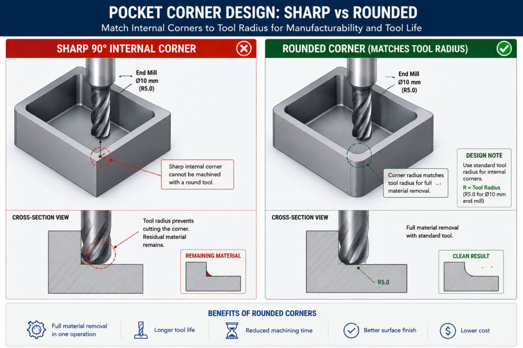
Every CNC constraint traces back to the same source: the cutting tool is a solid body that must physically reach the feature being cut, and its geometry determines what shapes it can produce. An end mill is a cylinder with cutting edges. When it plunges into a pocket and sweeps the perimeter, it leaves a radius at every internal corner equal to its own radius. That’s not a limitation of machine accuracy or operator skill. It’s a geometric consequence of the tool being round. The only ways around it are a smaller tool (slower, more fragile), EDM (spark erosion instead of a spinning tool), or a design that doesn’t call for a sharp corner there.
Understanding this changes how you approach feature design. The question stops being “what shape do I want here” and becomes “what shape can a tool produce here, and is that compatible with what I actually need.” For most brackets, housings, and structural components, the answer is a straightforward yes once the design adapts. Cases where the functional requirement genuinely conflicts with what a cutting tool can reach are actually rare, and almost always better solved by reconsidering the feature geometry than by accepting the cost of a workaround.
The Three Axes and What They Limit
Most CNC machining centres operate in three axes: X, Y, and Z. The tool reaches any point on the top surface and any vertical surface relative to the current setup. What it can’t reach without repositioning the workpiece are features on other faces, undercuts hidden behind an overhang, and surfaces sloped outside the range of vertical tool motion.
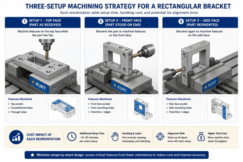
This is why setup count is such an important cost driver. Every time the workpiece is removed, flipped, and re-fixtured, the machine stops producing chips. Repositioning takes time, and re-fixturing introduces a small but real alignment uncertainty that accumulates across the part’s critical dimensions. Reducing a part from four setups to two doesn’t just roughly halve machining time; it also improves positional accuracy between features previously cut in separate setups.
Five-axis machining extends this by tilting or rotating the workpiece relative to the linear axes, reaching compound-angle surfaces and some undercuts in a single setup. It’s genuinely powerful for complex aerospace and medical components, but it costs more per hour, needs more sophisticated programming, and isn’t available at every shop. Commit to a five-axis requirement only after three-axis approaches have genuinely been exhausted, since the pool of shops that can bid narrows and the price rises noticeably once five-axis is a requirement.
CNC Feature Design Rules: The Reference Table
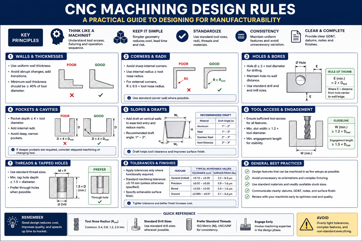
These eight rules are the ones that show up most often in shop feedback, worth checking on every drawing before it goes out for quoting.
| Feature | Rule / Guideline | Why It Exists | What Happens If Violated |
|---|---|---|---|
| Internal corner radius (pocket) | Match standard end mill radii: 0.5, 1.0, 1.5, 2.0, 3.0, 4.0, 6.0, 8.0, 10.0mm | End mills are cylindrical, leaving a radius equal to their own | Custom micro-tooling or EDM secondary operation needed |
| Pocket depth-to-width ratio | Max 4:1 for standard tooling; up to 6:1 with long-reach tooling | Deep narrow pockets need long, thin tools that deflect and chatter | Dimensional error, poor finish, shortened tool life, possible breakage |
| Hole depth-to-diameter | Through holes: no practical limit. Blind: 3:1 max standard; 5:1 with extended-reach drills | Deep narrow holes need extensions that deflect; chip evacuation is difficult | Drill wander, wall thickness violation, chip welding, breakage |
| Thread engagement depth | 1.0-1.5x diameter steel-into-steel; 1.5-2.0x steel-into-aluminum | Shallower threads strip under preload; deeper adds time with no gain | Thread strip-out under torque, especially in softer materials |
| Wall thickness (milled pocket) | 0.5mm minimum rigid materials, short feature height; 1.0mm practical general minimum | Thin walls deflect under cutting force, causing chatter and inaccuracy | Wall bows inward at mid-height, poor finish, out-of-tolerance |
| Boss/protrusion height | Max 4-5x base diameter for a standard end mill | Tall thin protrusions vibrate and deflect away from the tool | Poor finish, dimensional error, possible feature fracture |
| Counterbore vs. screw size | Diameter = head diameter + 0.5-1.0mm clearance; depth = head height + 0.2mm | Must clear the fastener head for correct seating | Head protrudes above surface, or contacts bore walls |
| Chamfers vs. fillets | Chamfers at 45° for standard tooling; fillets need a radius end mill | Chamfers use angled tools; fillets need a ball-nose or radius cutter | A 1mm fillet on every edge triggers a slow finishing pass on all of them |
Internal Corners: The Rule That Catches the Most Engineers
The internal corner radius rule is probably the most frequently violated rule in CNC machining, not because it’s complicated but because it’s easy to forget while focused on functional geometry. On a CAD screen, a pocket with sharp 90-degree internal corners looks perfectly clean and buildable. The machinist’s eye sees a feature that requires either a fragile micro-tool that cuts slowly and breaks often, or a standard end mill followed by a secondary EDM operation.
The fix is almost always free in CAD and costs nothing in the part’s function. If the corner radius needs to clear a mating component with a sharp corner, add a corner relief in the mating part instead of requiring a sharp corner in the pocket. If the radius is simply unconstrained, size it to the nearest standard end mill and the issue disappears. A 6mm internal radius lets any end mill up to 12mm diameter finish the corners, giving the shop far more flexibility than a 1mm radius would.
Below about 1mm internal radius, you’re in micro-machining territory. Tools at this scale are fragile, cut slowly, and need spindles running 20,000 to 50,000 RPM to maintain reasonable surface speeds. Cost per feature rises sharply, breakage risk is meaningful, and the range of shops that can produce it reliably narrows. This isn’t to say micro-machining is never appropriate, medical devices, optical mounts, and precision instruments genuinely need it sometimes, but it should be a deliberate choice against a known requirement, not an accidental consequence of a sharp corner in a standard bracket.
Tolerances and Surface Finish: Only as Tight as the Function Needs
One of the most reliable ways to add cost without adding value is specifying tolerances tighter than the application requires. This happens for a few common reasons: CAD title block defaults that carry a tolerance tighter than most features need, dimensions copied from a previous design, and a conservative instinct that tighter is always safer. None of those reasons are wrong in intent, but they all lead to a shop running additional operations or more extensive inspection to hit a number that serves no purpose in the finished assembly.
The discipline worth applying: for every toleranced dimension, ask what actually breaks if the tolerance were twice as loose. If the answer is genuinely nothing, the tolerance is tighter than needed. For most non-mating, non-locating dimensions on a structural part, a general tolerance of +/- 0.125mm to +/- 0.25mm is perfectly adequate, matching the standard tolerance classes documented in Machinery’s Handbook, and achievable without any special process consideration.
| Feature Type | Standard Tolerance | Achievable Tighter | Added Operation for Tighter |
|---|---|---|---|
| General machined dimension | +/- 0.125 to 0.250mm | +/- 0.05mm with careful setup | None standard; extra fixturing for +/-0.05 |
| Drilled hole diameter | +0.10/-0.00 (drilled nominal) | +/- 0.025mm (reamed) | Reaming adds one tool change, one pass |
| Bored hole diameter | +/- 0.025 to 0.050mm | +/- 0.005-0.010mm | Fine or jig boring; climate control |
| Tapped thread | ISO 6H (medium fit) | ISO 5H or 4H (close fit) | Machine tapping vs. hand; gauge verification |
| Flatness (milled) | 0.05-0.10mm over 100mm | 0.01-0.02mm over 100mm | Grinding or precision milling with temp stabilisation |
| Surface finish (as-milled) | Ra 1.6-3.2 μm | Ra 0.8 μm with fine finish pass | Fine pass at lower feed, higher speed |
| Surface finish (ground) | Ra 0.2-0.8 μm | Ra 0.025-0.1 μm (precision ground) | Cylindrical or surface grinding, secondary op |
| Hole pattern position | +/- 0.1-0.15mm diameter zone | +/- 0.025-0.05mm with jig boring | CMM verification, tight fixturing, thermal stabilisation |
Surface Finish Is a Secondary Operation, Not a Milling Setting
Surface finish finer than Ra 0.8 micron typically can’t be achieved by milling alone regardless of cutting parameters. Ra 0.4 micron or better needs a secondary process, grinding, lapping, or honing, each a separate production step with its own setup and cycle time. Specifying Ra 0.4 on a surface that serves no sealing, sliding, or tribological function adds an entire secondary operation for no functional benefit.
The practical approach: specify surface finish only where it matters functionally, and use the loosest specification that still meets the requirement. A sealing face needs smoothness for the seal to seat without leaking. A sliding contact needs a finish appropriate for its bearing pressure. Everything else can stay as-machined, typically Ra 1.6 to 3.2 micron, which costs nothing extra since it’s what standard milling produces without additional operations.
Material Machinability: How Material Choice Affects Cost
Material choice is one of the most consequential machining cost decisions, typically locked in early, before any features are designed. A designer who understands machinability characteristics upfront can sometimes cut machining cost by thirty to fifty percent with a material choice that still satisfies engineering requirements.
| Material | Machinability Rating | Key Consideration | Tool Life Impact |
|---|---|---|---|
| Aluminium (6061, 7075) | Excellent: 200-300% of free-cutting steel | Long, stringy chips need chip-breaker geometry | Very long tool life; carbide and HSS both work well |
| Mild steel (1018, 1020) | Good: 70-80% | Free-machining grades (1215, 12L14) are significantly easier | Moderate; carbide preferred for production runs |
| Stainless steel (304, 316) | Difficult: 40-50%; work-hardening is the challenge | Must cut continuously; carbide tooling mandatory | Short tool life; 303 free-machining much easier if allowed |
| Stainless steel (316L, duplex) | Very difficult: 30-40% | Rigid setup essential; flood coolant mandatory | Very short tool life; high tooling cost per part |
| Titanium (Grade 5, Ti-6Al-4V) | Difficult: 25-40%; low thermal conductivity | Low cutting speed mandatory; sharp tools, aggressive coolant | Short tool life; one of the highest tooling costs in common use |
| Hardened steel (>45 HRC) | Very difficult: better suited to EDM or grinding | Hard milling with CBN/ceramic possible on rigid machines | Very short tool life even with CBN |
| Copper and brass | Very good: 150-200% | Soft copper can smear at low speeds; leaded brass easiest | Good tool life, similar to aluminium |
| Engineering plastics (Delrin, PTFE, nylon) | Good but workpiece-dependent | PTFE is soft and deflects; nylon absorbs moisture | Excellent tool life; plastic doesn’t wear tooling significantly |
The Free-Machining Grade Trade-off
For most structural steels, free-machining grades exist that are substantially easier and cheaper to machine than standard equivalents, with only modest property compromises. 1018 is the workhorse structural grade with good strength and weldability. 1215, a resulfurized free-machining grade, machines at roughly twice the speed with better surface finish and longer tool life. If the application doesn’t need welding, heat treatment, or 1018’s slightly higher strength, switching to 1215 often halves machining cost for no functional penalty.
The same trade-off exists in stainless: 303 machines three to four times faster than 304, with better finish and much longer tool life, at the cost of weldability and slightly lower corrosion resistance in some environments. A lot of engineers default to 304 simply because it’s the most widely specified grade, without checking whether the application actually needs what 304 provides over 303, and that default carries a real cost penalty on every unit produced.
Setups and Fixturing: Designing for How the Part Sits in the Machine
Every time a machinist repositions a part, the clock runs but no chips get made. Fixturing, alignment, and probing each take time, and setup count is one of the clearest predictors of cost. A part needing three setups doesn’t simply cost 50 percent more than one needing two. The operator also has to re-establish the datum reference each time, small alignment errors accumulate between features cut in different setups, and a custom fixture may be needed if the geometry doesn’t lend itself to standard workholding.
Design for Standard Workholding
Standard workholding means a machine vise, a collet chuck, or toe clamps on a fixture plate. Parts with flat, parallel reference surfaces and enough clearance for vise jaws to grip without interfering with the cut features are the cheapest to set up and the least likely to trigger a call about needing a custom fixture. Round or organically shaped parts, or ones with features that conflict with standard vise jaw positions, need a custom fixture or an angled setup that introduces risk.
The practical habits: keep at least two opposite faces flat and parallel as datum surfaces for vise workholding, make sure features needed in each setup are accessible from the top without vise jaws blocking the tool path, and avoid features requiring the part to be fixtured at an angle, since angle plates and tilted fixtures add cost and setup time.
The 2+2+2 Setup Rule for Rectangular Parts
Think of a rectangular part’s six faces as three pairs: top and bottom, front and back, left and right. A well-designed three-axis part should have all its features accessible from at most three of those faces. Top-face features get cut in setup one, front or back face in setup two with the part stood on end, and a side face in setup three. That’s the practical limit of efficient three-axis machining without a rotary fourth axis or a five-axis machine, and designing within it keeps the part accessible to the widest pool of suppliers.
CNC Cost Drivers: What Makes a Part Expensive
Not all cost drivers are equally within a designer’s control, and not all carry equal weight.
| Cost Driver | Relative Impact | Design Changes That Reduce It | Red Flags in a Drawing |
|---|---|---|---|
| Number of setups | High: 20-40% per additional orientation | Design features on as few faces as possible | Features requiring more than one flip; holes on 5-6 faces |
| Tight tolerances | High, non-linear: 1.5-6x cost per tighter class | Specify no tighter than function demands | Tight tolerances on cosmetic features; blanket +/-0.025mm title block |
| Deep narrow pockets | Medium-High | Widen pockets for a stiffer tool; step the depth down | Depth-to-width above 4:1; narrow full-depth slots |
| Small internal corner radii | Medium | Match standard end mill sizes | Internal corners under 1.0mm without micro-machining need |
| Custom tooling or operations | Very High: weeks of lead time, high cost | Design to standard tool sizes and thread forms | Non-standard thread forms; radii matching no available tool |
| Surface finish requirements | Medium | Specify finish only where functionally needed | Ra 0.4-0.8 on surfaces with no sealing/bearing/mating function |
| Material removal volume | Medium | Remove only what the design needs | 50mm billet machined down to a 3mm plate |
| Part size vs. machine capacity | Low-Medium | Split oversized parts where the design allows | Parts approaching a 600-800mm three-axis envelope |
The Setup Count Problem Is Easy to Underestimate
Setup count is the cost driver most frequently underestimated by engineers without shop floor experience. A design requiring five setups doesn’t just add four extra repositionings’ worth of time. It also shrinks the pool of shops that can run the part economically, since tying up a machining centre for five operations is only profitable at certain volumes and price points. An engineer who reconsiders a four-setup layout and finds a way to do it in two hasn’t just cut unit cost; they’ve opened the part to a wider range of competitive bids, which often drives cost down further.
Worked Examples
The pump housing with EDM corners: A pump housing had a rectangular internal cavity for a sliding valve with square cross-section corners, so the designer specified a matching square cavity with zero-radius corners on all four internal walls. The sharp corners required EDM after milling, adding roughly 60 percent to machining cost and extending lead time from five to twelve days.
The redesign kept the valve body’s functional cross-section but added 2mm corner reliefs to the valve, matching the radius a 4mm end mill would leave in the housing cavity. The cavity became fully machinable with a standard end mill in one operation, and the valve still slid correctly since the reliefs didn’t interfere with any sealing or guidance surface. The EDM step was eliminated entirely, machining cost dropped roughly 45 percent, and lead time returned to five days, all from an hour of CAD work with zero impact on function.
The instrument bracket with unnecessary surface finish: An optical instrument bracket carried a Ra 0.4 micron finish requirement on all machined surfaces, inherited from the finish standard of the optical instrument it mounted. The bracket itself was purely structural, none of its surfaces were optical, sealing, or sliding contacts. That blanket finish requirement meant grinding every face as a secondary operation, accounting for sixty percent of total machining cost.
The revision set structural faces to Ra 1.6 micron as-milled, keeping Ra 0.4 micron only on the two precision datum surfaces where the instrument actually seated. Grinding dropped from six faces to two. Machining cost fell roughly 40 percent and lead time shortened from eight days to four, with zero change to the instrument’s optical performance since the surfaces that actually mattered kept their required finish.
Frequently Asked Questions
What is the minimum internal corner radius I should design for? The practical floor is set by the smallest standard end mill your shop carries, typically 1mm diameter for a 0.5mm corner radius, but that size is fragile and slow. A more practical minimum for typical work is 1.5mm to 2.0mm, matching common, robust 3mm and 4mm tools. Designing to 3mm or 6mm gives even more tool selection flexibility, usually translating to faster cycle times and lower cost. Choose the largest radius the design will tolerate functionally, matched to a standard end mill size.
How many setups should I aim for? One setup is ideal wherever function allows it. Two is the practical target for most rectangular parts. Three is the practical limit for standard three-axis equipment without a rotary axis. Once a part needs four or more, cost rises substantially and the pool of shops that can run it economically narrows. If a design is heading toward four or more setups, ask whether features can be relocated or consolidated, or whether five-axis machining would bring the setup count down to one or two and improve the economics for your volume.
Does material choice really affect machining cost that much? Yes, significantly. The difference between 303 stainless (free-machining) and 316 for the same part can be a factor of two to three in cycle time alone, with tool wear compounding it further. The difference between 6061 aluminium and Ti-6Al-4V for a structurally equivalent part can run five to ten times in total machining cost. For meaningful production volumes, machinability deserves the same attention as structural material selection, since there are often two or three material options within a given structural requirement with very different machinability profiles.
When should I use a chamfer instead of a fillet on an external edge? Use a chamfer whenever the purpose is deburring, lead-in for assembly, or a cosmetic break, and a fillet isn’t structurally required. A 45-degree chamfer is cut in a single fast pass. An external fillet needs a ball-nose or radius end mill making a slower finishing pass around every edge that carries the callout. On a part with many external edges, specifying fillets everywhere can add a full finishing operation. Reserve fillets for features where the radius is functionally required, like a fatigue-critical wall-to-floor transition, or a load-distributing contact surface.
Why do tighter tolerances cost so much more? Because tighter tolerances usually trigger a step change in process rather than a smooth increase in care. A hole at a standard drilling tolerance needs one operation. The same hole at +/-0.025mm needs reaming: an additional tool, an additional pass, additional inspection. Flatness at 0.05mm over 100mm might be achievable with careful milling; 0.005mm needs grinding in a temperature-controlled environment. Each tighter step tends to require an additional operation or a different process entirely, which is why tolerance cost looks like a series of jumps rather than a smooth curve.
What’s the maximum depth-to-width ratio for a CNC pocket? The standard guideline is 4:1 for pockets machined with a standard-length end mill. At that ratio, the tool already experiences meaningful deflection under cutting load, affecting finish and accuracy, particularly at the bottom corners. Above 4:1 you need long-reach tooling, which deflects more, cuts more slowly, and costs more. Above 6:1, options are accepting long-reach tooling’s cost, widening the pocket at deeper sections, splitting the part into two conventionally machined pieces, or switching to EDM for the deep sections, which avoids deflection but runs considerably slower than milling.
Key Takeaways
The bracket from the opening example eventually got made, at a higher cost and longer lead time than expected. That’s not the worst outcome, and it’s far from unusual. Most engineers learn these rules from experience, from parts that cost too much, took too long, or generated a call from the shop about a feature the drawing hadn’t accounted for.
The goal is to move that learning earlier, before a drawing goes out, before tooling is committed, while the features are still adjustable in CAD at no cost. These rules aren’t creative constraints on what a part can look like. They’re physical facts about what a spinning cylindrical tool can and cannot do through three or five axes. A designer who has internalised them thinks differently about feature geometry, not less ambitiously, but with a natural awareness of which choices translate directly into cost and lead time.
Run through the reference tables whenever a CNC drawing is close to final. Check internal corner radii against the feature rules. Audit every tight tolerance. Count the setups the current feature layout requires and whether any change would reduce it. Those checks cost minutes in CAD. The problems they catch cost days or weeks and real money once the drawing is at a shop.