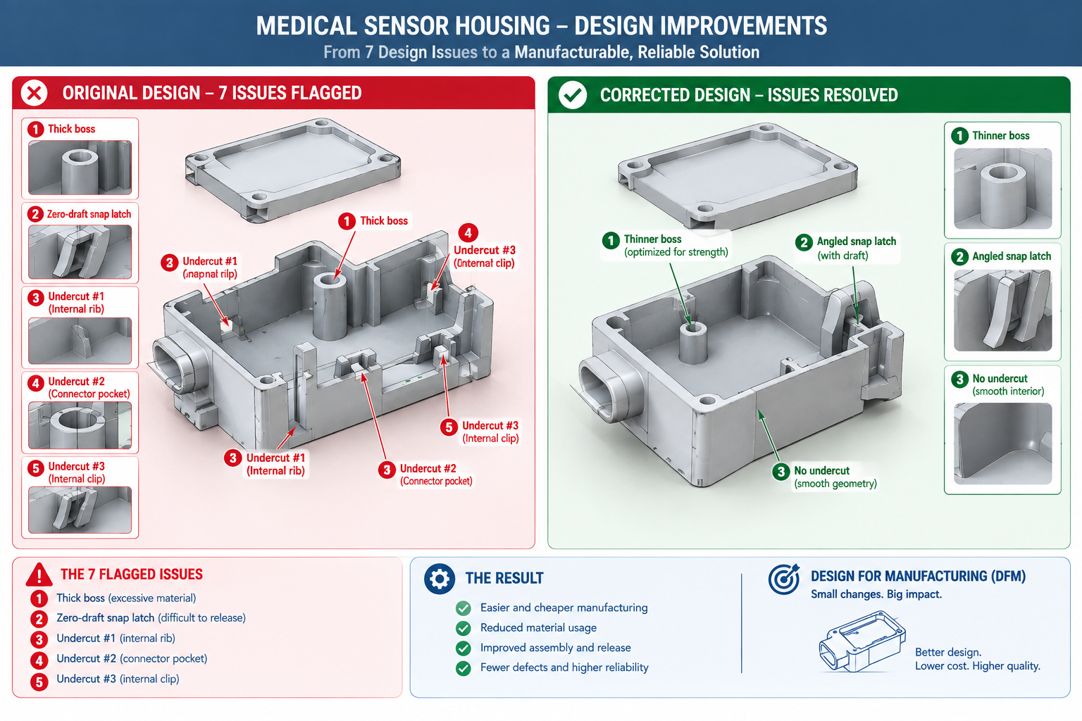
A product design team spent eight months developing a small medical sensor housing. The design was elegant: organic curves, minimal visible fasteners, integrated cable management, a two-part snap-fit enclosure that felt premium in the hand. Wall thicknesses ranged from 0.9mm at the curved flanges to 4.2mm where the window mounting boss met the shell wall. The snap latches had zero draft, since draft would have complicated the snap face geometry. Three internal undercuts wrapped around the USB port opening.
The tooling quote came back with seven flagged design issues, four required side actions, and a price more than double the budget. The programme paused for six weeks of redesign, essentially rebuilding what eight months of work had produced, now constrained by rules that had been available at the start but weren’t part of the initial design process.
| Quick answer: Manufacturing constraints exist because every process is bound by physics, molten plastic has to fill a cavity and eject cleanly, a rotating cutting tool can only reach what its geometry allows, sheet metal can only bend as tight as its ductility permits. The single highest-impact decision a product designer makes isn’t a geometric rule at all: it’s choosing the right process for the target production volume before any detailed geometry exists, since that choice determines which constraints apply and what tooling investment gets recovered. |
This is the scenario manufacturing constraints exist to prevent. The rules aren’t bureaucratic obstacles to creative design. They’re descriptions of what physical processes can and cannot do, most useful when known before a design is finalised rather than discovered when a quote comes back with problems.
Why Manufacturing Constraints Are Process-Specific
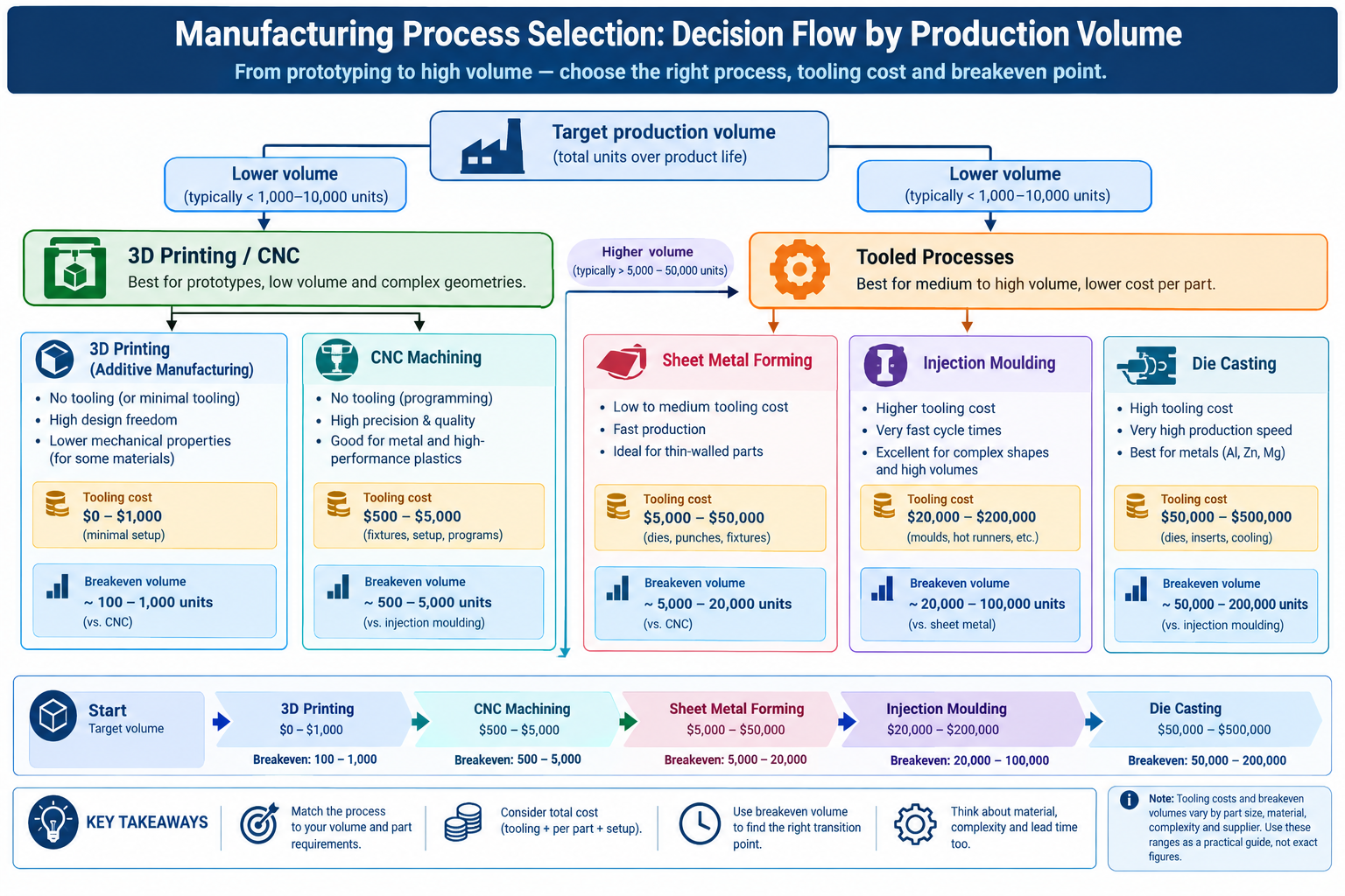
Every manufacturing process imposes constraints that come directly from its physics. Injection moulding pushes molten plastic into a cavity under pressure, and the plastic has to fill completely and eject cleanly, generating the wall thickness, draft, and undercut rules. CNC machining removes material with a rotating cylindrical tool, and the tool geometry generates the internal corner radius constraint, the pocket depth limit, and the multi-setup cost penalty. Sheet metal forming bends flat material around a tooling radius, and the material’s ductility and springback generate the minimum bend radius and feature-to-bend-line proximity rules.
None of these constraints are arbitrary; each is a physical consequence of how the process works. A designer who understands the physics behind two or three constraints tends to figure out related ones without looking them up, since the same underlying mechanism generates multiple related rules. Understanding that injection moulded walls need draft because the part shrinks onto the core as it cools and has to slide off the steel without tearing is more durable knowledge than memorising “1 degree per side,” since the physical understanding generates the correct angle for any texture depth without a table lookup.
Understanding the mechanism also clarifies when a constraint applies at all. Draft on a flat horizontal face parallel to the mould opening direction is irrelevant, since that face never slides across the mould steel during ejection. Draft on a vertical face is essential, since that face slides along the steel for the entire ejection stroke. Knowing why makes it immediately clear which surfaces need draft and which don’t.
Ten Processes, Their Constraints, and Their Sweet Spots
This comparison helps with the earliest and most consequential decision in product development: which process fits this part, at this volume, with these material and performance requirements.
| Process | Min Feature Size | Typical Tolerance | Volume Sweet Spot | Key Constraint |
|---|---|---|---|---|
| Injection moulding | 0.4mm features; 0.8mm min wall | +/-0.1 to 0.25mm | 10,000 to millions | Uniform wall thickness (within 15%); draft on all vertical faces; no undercuts without side actions |
| CNC milling | 0.5mm end mill; 1mm practical | +/-0.025 to 0.1mm | 1 to 1,000 | Internal corners always carry a radius; pocket depth max 4x width; each setup adds 20-40% cost |
| CNC turning | 0.1mm feature detail | +/-0.01 to 0.05mm | 1 to 10,000 | Features must be rotationally symmetric; off-axis holes need a separate milling setup |
| Sheet metal (press brake) | 1mm hole (punched); 0.5mm laser | +/-0.5-1.0mm bent; +/-0.1mm flat | 10 to 100,000 | Holes distort within 2.5x thickness of a bend; springback must be designed in |
| Die casting (aluminium) | 0.8mm wall; 0.4mm HPDC | +/-0.1 to 0.3mm | 5,000 to millions | Draft required (1-3°); undercuts need slides; porosity risk in thick sections |
| Sand casting | 5mm wall; 3mm with chill | +/-0.5 to 2.0mm | 1 to 500 | Large draft required (2-5° per side); generous internal corner radii; core prints needed |
| Forging | Complex 3D; limited thin sections | +/-0.5 to 2.0mm | 500 to millions | Flash line runs along the parting plane; cannot form internal cavities without machining |
| 3D printing (FDM/SLS/SLA) | 0.1-0.4mm | +/-0.1 to 0.3mm | 1 to 500 | Anisotropic strength (weakest across layers); supports needed for overhangs > 45° |
| Laser cutting (flat) | 0.1mm kerf | +/-0.05 to 0.1mm | 1 to any volume | 2D only; slight edge taper at high thickness; dross removal on thick cuts |
| Waterjet cutting (flat) | 0.5mm after kerf | +/-0.1 to 0.25mm | 1 to moderate | 2D only; no heat-affected zone; slower than laser or plasma for thick material |
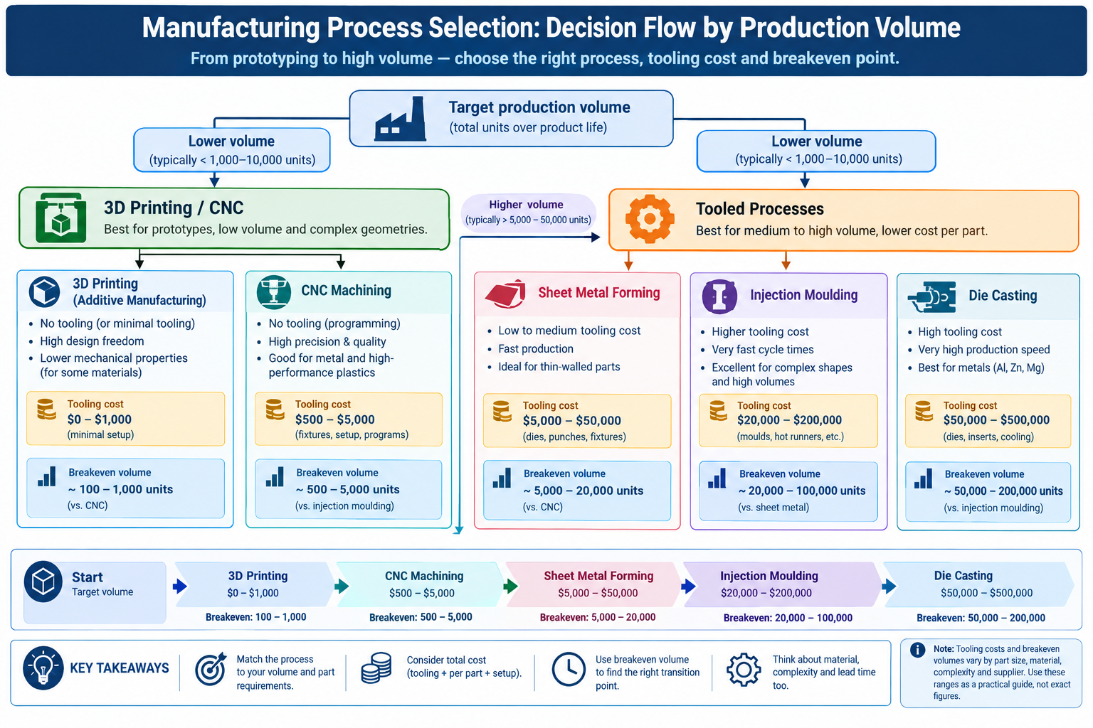
Volume and Process Selection: The Tooling Cost Trade-off
The most consequential decision a product designer makes, before any geometry is finalised, is which process to use at which production volume. This decision determines tooling investment, achievable unit cost, available tolerances and finishes, and the constraints the design must satisfy. Getting this right early is far more valuable than optimising within a process chosen without weighing whether it fits the volume.
The fundamental trade-off is between tooling investment and unit cost. Tooled processes (injection moulding, die casting, progressive stamping) carry high fixed costs but low per-part variable cost once tooling is paid off. Toolless processes (CNC machining, 3D printing, laser cutting) carry no fixed cost but higher variable cost per part, since each part needs fresh machine time. The crossover point, where total tooled-process cost drops below total toolless-process cost at the same volume, is the volume breakeven.
| Production Volume | Typically Correct Process | Tooling Cost Range | Unit Cost Range | Lead Time to First Parts |
|---|---|---|---|---|
| 1-5 units (proof of concept) | 3D printing; CNC for structural prototypes | None or minimal | $20-$500 per part | 1-5 days print; 5-15 days CNC |
| 5-100 units (pilot/pre-series) | CNC machining; 3D printing; sheet metal | $0 CNC; $500-5,000 soft-tool mould | $50-$2,000 per part | 5-15 days CNC; 4-8 weeks soft tool |
| 100-1,000 units | CNC if complex; sheet metal; die casting if geometry suits | $5,000-$80,000 for tooled processes | $10-$200 machined; $3-$30 cast | 6-14 weeks tooled |
| 1,000-10,000 units | Injection moulding; aluminium die casting; sheet metal | $15,000-$200,000 | $1-$20 injection moulded; $3-$50 die cast | 8-16 weeks tooling |
| 10,000-100,000 units | Injection moulding; die casting; progressive die sheet metal | $50,000-$500,000 | $0.10-$5 per part | 12-24 weeks tooling |
| 100,000+ units (mass production) | Injection moulding; die casting; progressive stamping; hot stamping | $200,000-$2,000,000 | $0.02-$2 per part | 24-52 weeks major tooling |
The Breakeven Calculation: Simple But Often Skipped
The calculation is straightforward: total cost of a tooled process is tooling cost plus unit cost times volume. Total cost of a toolless process is unit cost times volume. Breakeven volume equals tooling cost divided by the unit cost difference between the two processes.
For a plastic part costing $8 per unit by CNC machining and $0.50 per unit by injection moulding, with a $40,000 tooling investment: breakeven volume = $40,000 / ($8 – $0.50) = $40,000 / $7.50 = 5,333 units. Below that, CNC is cheaper overall. Above it, injection moulding is cheaper overall.
This calculation is rarely wrong in direction, and it’s almost never done at the point where the process decision actually gets made. Teams commit to injection moulding because “it will be a consumer product” without checking whether the target volume crosses the breakeven, or they commit to CNC because “it’s a prototype” without realising the actual pilot volume already sits above the point where moulding would be cheaper over the programme lifetime. The calculation takes fifteen minutes and changes the decision more often than most designers expect.
Material-Process Compatibility: The Constraints Before the Constraints
Before any geometric design constraint applies, there’s a more fundamental question: is this material compatible with this process at all? Not all materials can be processed by all processes, and combinations that look plausible in theory can be impractical or extremely expensive in reality.
| Material | Injection Moulding | CNC Machining | Sheet Metal Forming | Die Casting | Key Constraint |
|---|---|---|---|---|---|
| Aluminium alloys | Not applicable | Excellent | Good (5052, 3003); difficult (6061-T6) | Excellent, primary process | 6061-T6 needs annealing for tight bends; die cast alloys (A380) differ from wrought |
| Mild steel | Not applicable | Good | Excellent, standard material | Not typical | Weld distortion in thin gauge; scale/rust needs coating |
| Stainless steel | Not applicable | Difficult (work-hardening) | Moderate; higher springback | Not common | 303 free-machining grade avoids work-hardening issues |
| Engineering thermoplastics | Excellent, primary process | Good (Delrin/POM best) | Not applicable | Not applicable | Some plastics absorb moisture, affecting post-mould dimensions |
| Copper and brass | Not applicable | Excellent (brass); good (copper) | Good at annealed temper | Possible, not common | Galvanic corrosion risk with steel fasteners |
| Titanium alloys | Not applicable | Difficult, expensive | Very limited | Not practical | Cost driven by tool life and cutting time |
| High-performance polymers (PEEK, PTFE) | Possible with high-temp tooling | Good (PEEK); care needed (PTFE) | Not applicable | Not applicable | PEEK injection moulding needs 150-200°C tool temperatures |
| Elastomers (silicone, TPU) | LSR moulding; TPU injection moulded | Limited, soft materials deflect | Not applicable | Not applicable | LSR requires dedicated tooling separate from thermoplastic tooling |
The Cost of Getting Material-Process Compatibility Wrong
Some mismatches are obvious, specifying stainless steel for injection moulding is clearly wrong since one’s a metal and the other’s a plastics process. The more dangerous mismatches are plausible in principle but problematic in practice: specifying 6061-T6 aluminium for die casting (the wrong alloy family, which uses A380 or A360), specifying glass-filled nylon for a part that needs adhesive bonding (glass fill significantly reduces bond strength), or specifying PEEK for injection moulding without accounting for the $200,000 to $500,000 cost of a high-temperature tool.
The habit that prevents these problems is checking material-process compatibility as one of the first steps of design, not as a review after the design is complete. A five-minute conversation with a supplier who specialises in the target process, asking whether the specified material is standard for their process, catches these issues at zero cost, following the process capability principles documented in Kalpakjian and Schmid’s Manufacturing Engineering and Technology. The same discovery after a drawing release and a tooling quote takes weeks to resolve.
Twelve Universal Manufacturing Constraints
Beyond the process-specific rules in the companion articles of this series, these twelve constraints apply across multiple processes and are worth carrying as working knowledge.
| Constraint | Rule of Thumb | Applies To | What Breaks If Ignored |
|---|---|---|---|
| Wall thickness uniformity | Keep variation within 10-15% of nominal | Injection moulding, die casting, thermoforming | Sink marks, warping, voids, scrap on first shots |
| Draft angle on vertical faces | 1-2° minimum; add 1° per 0.025mm texture depth | Injection moulding, die casting, forging | Part sticks in mould; drag marks; tool damage |
| Internal corner radius | Minimum 1x wall thickness; match standard tool sizes | CNC milling, injection moulding, die casting | Stress concentration; custom tooling required |
| Undercut/side action | Avoid unless volume justifies tooling cost | Injection moulding, die casting, forging | Slides/lifters add 20-50% tooling cost |
| Feature-to-bend-line proximity | Holes at least 2.5x thickness + bend radius from bend line | Sheet metal forming | Features distort; holes become ovals |
| Minimum flange length | 3x thickness + inside bend radius | Sheet metal press brake bending | Inaccurate, inconsistent bend angle |
| Pocket depth-to-width ratio | Maximum 4:1 with standard tooling | CNC milling | Tool deflection, chatter, possible breakage |
| Tolerance vs. process capability | Commercial tolerance needs no special process; each tighter step adds 1.5-6x cost | All machined/formed processes | Over-tolerancing adds cost with no functional benefit |
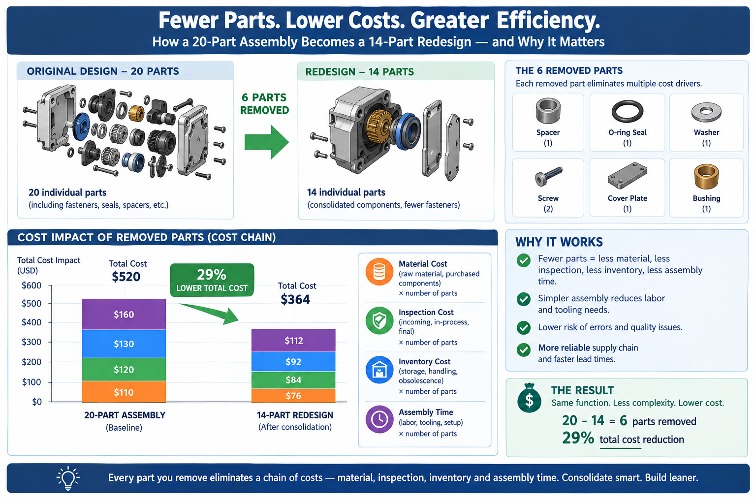
| Part count in assemblies | Ask “can this be one part?” before adding a second | All assembly designs | Unnecessary assembly time, inventory, failure points |
| Springback in bending | Design the bend angle to compensate; document it | Sheet metal, roll forming, tube bending | Part springs to wrong angle; assembly interference |
| Material-process compatibility | Check compatibility early | All processes | Wrong material for the process; late-stage redesign |
| Tooling investment vs. volume breakeven | Calculate cost per part at target volume including amortisation | Injection moulding, die casting, progressive stamping | Tooling spend never recovered at actual production volume |
Part Count: The Constraint That Compounds Across the Entire Product
Of these twelve, part count reduction has the largest potential impact and is the most frequently overlooked, precisely because it’s not a feature-level constraint. It applies to the whole assembly, requiring a step back from individual part optimisation to ask whether the assembly could be simplified.
Each separate part carries its own cost chain: material, machining or forming, quality inspection, supplier management, inventory, picking during assembly, and any fasteners used to join it. Consolidating two parts into one eliminates most of that chain for the second part, on every unit produced. The savings aren’t dramatic for a small two-part assembly with limited volume. They become significant for a twenty-part assembly at a hundred thousand units per year, where the difference between twenty parts and fourteen means six fewer cost chains multiplied across a hundred thousand units.
The systematic question, drawn from the Boothroyd-Dewhurst design for assembly criterion, is: does this part move relative to adjacent parts, does it need a different material, and does it need to be disassembled for service? If the answer to all three is no, there’s a good case for consolidating it into a single feature on an adjacent piece.
When Manufacturing Constraints Are Discovered Determines Their Cost
Every constraint not considered during design gets discovered eventually: by the product designer in a review, the mould maker in a quote, the operator at the press brake, or the inspector at the quality station. The cost of resolving it grows by roughly an order of magnitude at each successive stage. A wall thickness problem caught in design review costs an hour of CAD time. The same problem caught after tooling is cut costs tool rework, schedule delay, and possibly scrapped first-article parts, together perhaps a hundred times the design review fix.
This asymmetry is the entire business case for knowing manufacturing constraints at the design stage rather than learning them from supplier feedback. The knowledge itself is free. The cost is in when it’s applied, and it’s minimised the earlier it’s applied.
The Design Review as a Manufacturing Constraint Check
The most practical institutional way to apply constraints early is a structured design review focused specifically on manufacturability, distinct from the structural and functional reviews that happen as a matter of course. A manufacturing-focused review asks a different question, not “will this carry the load” but “can this be made, at this volume, with the process specified, by a supplier with reasonable capability for these features.” These are engineering questions that need manufacturing knowledge to answer, whether from a manufacturing engineer, a supplier representative, or a designer who has studied the process-specific guidelines this series covers.
The twelve-item table above is one framework for structuring that review: a checklist workable in thirty to sixty minutes for a typical design, checking each part against the constraints for its intended process. None of the checks need specialised equipment. They need knowing what to look for while the design is still on screen.
Worked Examples
The medical sensor housing: The housing from the opening example, eight months in design before the tooling quote revealed seven problems, could have caught all of them with a constraint checklist during design. The wall thickness variation from 0.9mm to 4.2mm was far outside the 10-15% rule; the 4.2mm boss should have been redesigned to 60% of the adjacent wall with a gusset rib. Zero draft on the snap faces meant the part couldn’t eject without surface damage; a minimum one degree on the non-functional face would have worked without compromising the snap function.
The three USB port undercuts could have been redesigned as through-features formed by two mould halves at the parting surface, or repositioned to allow core pull in the mould opening direction.
The tools to catch these issues, wall thickness analysis, draft analysis, and a pull-direction undercut check, were standard features in the CAD package used from day one. Eight months of design could have been eight months of constraint-aware design instead. The six weeks of post-quote redesign was time lost entirely.
The enclosure that should have been sheet metal, not machined: An industrial instrument enclosure was designed as a machined aluminium block with milled pockets for internal electronics, needing four setups and several precision tolerances on PCB mounting bosses. At an estimated $320 per unit for a target run of 800 units, total machined cost was $256,000.
A volume breakeven check against sheet metal told a different story. A press brake-formed, laser-cut version with PEM-nut fastener inserts for PCB mounting had an estimated unit cost of $45, with no tooling investment for the standard sizes involved. At 800 units, total sheet metal cost was $36,000. The IP54 weatherproof rating, 0.2mm PCB mounting positional accuracy, and hard-anodised finish requirements were all achievable in sheet metal with appropriate gasket design and CMM-checked PEM nut locations. The switch saved roughly $220,000 on this run while meeting every functional requirement.
The machined option hadn’t been obviously wrong at the concept stage; it was chosen because the team was comfortable with machined enclosures and never evaluated the sheet metal alternative. The thirty-minute breakeven check made the comparison explicit and changed the decision. The constraint that unlocked the saving wasn’t a geometric rule. It was process selection based on volume.
Frequently Asked Questions
How early in the design process should manufacturing constraints be considered? From the first sketch. The most consequential decisions, which process and which material, are made or implied before any geometry exists, at the concept stage where product category and approximate volume are first established. A consumer product at high volume implies injection moulding, which implies thermoplastics, which implies wall thickness uniformity, draft, and every other injection moulding rule, all before a single wall is modelled in CAD. Confirm the process-versus-volume decision before detailed design begins, not after a tooling quote reveals it was wrong.
What is the most important manufacturing constraint for a designer working across multiple processes? Wall thickness uniformity in moulded and cast parts is probably the most impactful geometric rule, since violations are both common and highly visible: sink marks on a cosmetic surface are exactly the defect customers notice. But the constraint with the largest programme-level impact is the volume breakeven calculation, since choosing the wrong process for a given volume doesn’t just create a bad part, it creates bad product economics, which is much harder to fix than a sink mark.
Can 3D printing replace injection moulding for production parts? For some applications and volumes, yes. Industrial processes like SLS, MJF, and DMLS produce functional parts in engineering-grade materials at tolerances competitive with injection moulding for low to moderate volumes. The practical limits are unit cost (higher than moulding above roughly 500 to 1,000 units for most sizes), a narrower material range, and surface finish showing layer lines unless post-processed. For volumes below a few hundred units, complex geometries that would need expensive tooling, or evolving designs, 3D printing is often the better choice. Above a few thousand units in a stable design, injection moulding is almost always lower total cost.
What does “design for manufacture” actually mean in practice? It means applying knowledge of how each process works to the design decisions made at the CAD stage, so the resulting part is producible by the chosen process, at the intended cost, without surprises at tooling or fabrication. It’s not a separate analysis step added at the end. It’s a way of thinking about geometry integrated into how the design is built, asking “can a tool reach this corner,” “will this wall cause a sink mark,” “do these holes move when this face bends” throughout modelling rather than after it.
How do I know which manufacturing process to specify for a new product? Start with production volume and unit cost target, since these determine which processes are economically viable. At a few hundred units, CNC machining and sheet metal are typically the only practical metal choices, with 3D printing or soft-tool moulding for plastics. At tens of thousands, injection moulding and die casting become cost-competitive. At hundreds of thousands, progressive stamping and other high-volume processes fit. Within the economically viable options, check material-process compatibility, then check whether functional requirements are achievable. If multiple processes clear all three bars, choose based on team experience or the strongest local supplier base.
Why does adding a side action to an injection mould add so much cost? A side action is a moving mechanism inside the mould that travels perpendicular to the opening direction to form an undercut, requiring precision-machined steel, guide rails, locking mechanisms, and return springs. Each slide needs its own design, machining, fitting, and debugging. A simple slide might add 15 to 25 percent to tooling cost; a complex compound-motion slide might add 40 to 60 percent. Three or four slides, as in the medical housing example, can more than double tooling cost relative to an undercut-free design, which is why the rule is to eliminate undercuts where possible and budget explicitly when they’re genuinely necessary.
Key Takeaways
The sensor housing that took six weeks to redesign, and the instrument enclosure that could have been sheet metal all along, share the same underlying issue: the constraints that would have changed the design decisions were available but weren’t part of the conversation at the right time. None of this is specialised knowledge requiring years of manufacturing experience. It’s available in published guidelines, supplier conversations, and process-specific references.
The shift that makes manufacturing constraints useful rather than frustrating is treating them as information about what a process does well, not restrictions on what a designer can create. Injection moulding produces thin, uniform walls with complex geometry and integrated features at tolerances machining can’t match at scale, as long as the design respects what the process needs. CNC machining produces any machinable geometry to tight tolerances without tooling investment, as long as the design respects what a cutting tool can reach. Sheet metal produces lightweight, strong enclosures cheaply at almost any volume, as long as the design respects how the material bends.
Every process constraint is a description of what that process does well, stated as a boundary condition. Designers who understand that, who know enough about several processes to design for them deliberately rather than discovering the limits from suppliers, get from first quote to first production more smoothly, more cheaply, and with fewer detours.