Tag: manufacturing

  • Why GD&T Is Not Optional in High-Precision Manufacturing

    Why GD&T Is Not Optional in High-Precision Manufacturing

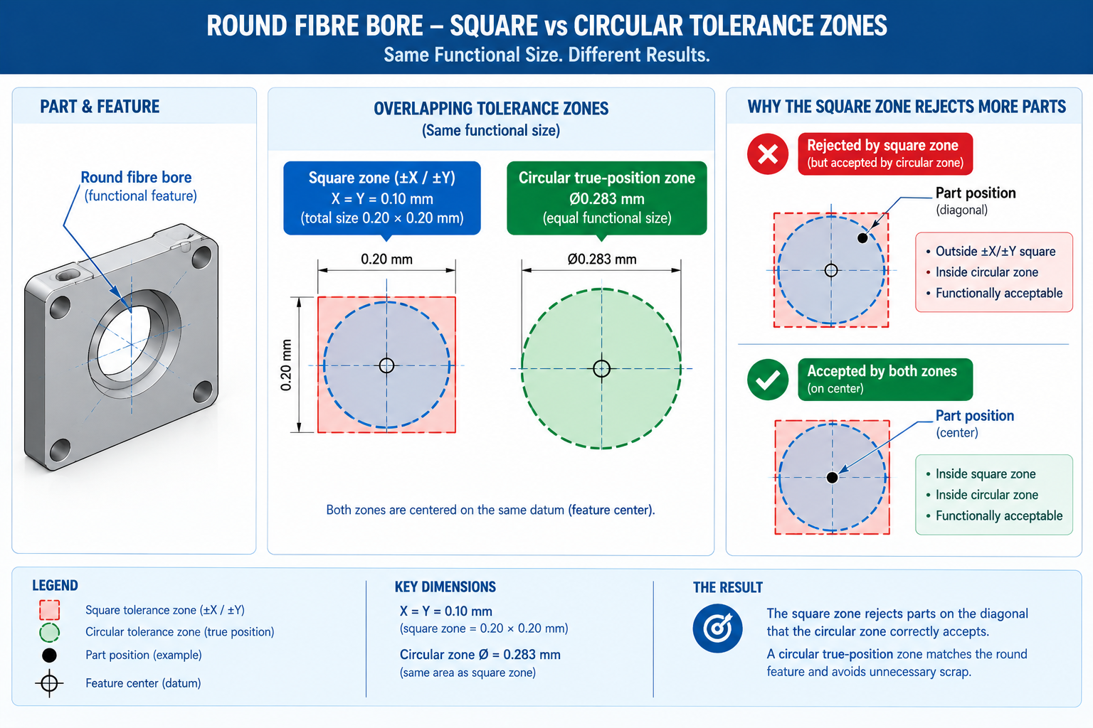
    A precision optics manufacturer supplying laser alignment fibre ferrules to a medical device programme had been rejecting roughly one in twenty parts at final inspection for six months, all for the same reason. The fibre bore, dimensioned with a conventional plus/minus 0.01mm on both X and Y from the ferrule’s outer edge, measured outside tolerance on the diagonal even though the parts assembled and aligned correctly on the bench every time.

    The rejected parts weren’t defective. The square tolerance zone created by two independent linear dimensions was smaller on the diagonal than the actual functional clearance the fibre needed, so parts fully acceptable for their optical function were failing a tolerance zone shape that didn’t match the round bore and round fibre it was meant to control.

    Quick answer: Switching to a true-position tolerance with a circular zone of the same functional size, referenced from an explicit datum reference frame, eliminated the false rejections entirely without loosening the actual functional requirement by a single micron. The fibres that failed inspection for six months had never been out of tolerance for their function; they’d been out of tolerance for a drawing convention that didn’t describe that function correctly. In high-precision industries, the cost of a tolerancing method mismatched to a part’s actual geometry isn’t academic. It shows up directly in scrap rate, inspection disputes, and warranty claims.
    Diagram comparing a square plus-minus tolerance zone to a circular GD&T position zone for a round fibre bore

    This article sets out why GD&T isn’t optional in aerospace, medical device, semiconductor, automotive, optics, and precision tooling manufacturing: the industries where it’s applied and why, how it differs functionally from conventional plus/minus tolerancing, the real cost of GD&T errors at each production stage, and worked examples showing the argument in practice.

    What Makes High-Precision Industries Different

    Every manufactured part has tolerance somewhere. The question in high-precision industries isn’t whether tolerance matters but how little margin exists to absorb a tolerancing method that doesn’t match the part’s function. A consumer bracket with a 0.5mm hole position tolerance has enough margin that an inefficient tolerance zone shape rarely causes a rejected part. A wafer-handling end-effector with a 0.005mm positional tolerance has none of that margin: the gap between a matched and mismatched tolerance zone can be the entire tolerance budget.

    High-precision industries share three structural traits that make GD&T’s discipline, rather than its absence, the deciding factor in whether a programme succeeds. First, multiple independent facilities measure the same part, a supplier, a sub-tier shop, incoming inspection, and assembly may each set up their own measurement, and without an explicit datum reference frame those measurements won’t agree.

    Second, the cost of a missed error rises sharply the further downstream it’s caught, making design-stage precision in the tolerancing method itself a direct lever on total programme cost. Third, the features being controlled are often not simple linear dimensions, aerofoil profiles, optical surfaces, and complex mating geometries can’t be fully described by plus/minus dimensioning at all, regardless of how tight the tolerance is made.

    Where GD&T Carries the Most Weight

    IndustryTypical Precision RequirementWhere GD&T Is AppliedConsequence of a GD&T Failure
    Aerospace structures and enginesPositional 0.02-0.10mm on fastener patterns; profile 0.05-0.25mm on turbine aerofoilsWing-to-fuselage joints, engine mounts, blade root fixings, actuator linkagesFastener holes that don’t align across mating structures; blade profiles disturbing airflow or causing vibration fatigue
    Medical device manufacturingPositional 0.01-0.05mm on implant mating features; profile on joint surfacesHip/knee implant articulating surfaces, surgical instrument tips, drug-delivery sealsImplants that don’t mate correctly with surgical instrumentation; seals compromising a sterile drug pathway
    Semiconductor equipmentPositional/flatness 0.001-0.01mm on wafer chucks, stages, fixturesWafer handling end-effectors, stage guideways, chamber door seals, alignment pinsA wafer placed off-centre by microns, failing an entire lot’s lithography alignment
    Automotive powertrain and chassisPositional 0.05-0.15mm on engine block bores and gear housingsCrankshaft/camshaft bearing bores, gear housing centre distances, brake caliper facesBearing bores out of alignment causing premature wear; gear noise or reduced service life
    Precision optics and photonicsPositional/angular 0.005-0.02mm on lens barrels, mirror mounts, fibre fixturesLens cell bores, mirror mounting pads, fibre ferrule bores, laser cavity mountsA decentred lens element introducing aberration that degrades image quality or beam pointing
    Injection mould and toolingPositional 0.02-0.08mm on core-to-cavity alignment featuresGuide pin/bushing bores, ejector pin holes, parting line profiles, cooling channel positionsCore-to-cavity misalignment producing flash or wall-thickness variation across thousands of cycles

    GD&T Compared to Conventional Plus/Minus Tolerancing

    The fibre ferrule story illustrates the central argument for GD&T: it isn’t simply a stricter or more formal system, it’s a geometrically more accurate description of the same functional requirement. A round hole locating a round fastener has a round functional tolerance zone; describing that zone with two independent linear dimensions produces a square zone that doesn’t match the geometry of what’s actually being controlled. In low-precision work, margin absorbs the mismatch. In high-precision work, the mismatch is often the entire difference between a part that passes and one that’s unnecessarily scrapped, or between a part that passes inspection and one that silently fails to perform.

    AspectConventional (Plus/Minus)GD&T ApproachTypical Outcome Difference
    Tolerance zone shapeSquare zone from independent X/Y tolerancesCircular positional zone sized to the functional clearanceUp to 57% more usable tolerance for the same functional clearance
    Datum referenceInconsistent mix of edges or arbitrary origins chosen for drafting convenienceExplicit, prioritised datum reference frame tied to assembly functionEliminates the “passed inspection, failed assembly” failure mode
    Bonus toleranceNot available; position tolerance stays fixed regardless of hole diameterMMC modifiers allow additional tolerance as size departs from worst-caseCan add 0.05-0.20mm of usable positional latitude with no assembly risk
    Form controlSize tolerance alone; a shaft can be barrel-shaped or lobed within its diameter limitIndependent form controls (flatness, circularity, cylindricity) constrain shapePrevents field failures (seal leaks, bearing noise) size tolerancing alone can’t catch
    Orientation and profileAngularity and shape typically implied, not explicitly tolerancedExplicit angularity, perpendicularity, parallelism, and profile controlsEnables verification of freeform and curved surfaces plus/minus can’t describe
    Inspection repeatabilityAmbiguous reference point; different inspectors may choose different edgesDatum reference frame and feature control frames give one unambiguous methodRemoves the largest source of measurement disagreement between facilities

    Bonus Tolerance: The Benefit Conventional Dimensioning Cannot Offer

    MMC modifiers illustrate why GD&T outperforms conventional tolerancing rather than simply replacing it with different notation. A hole’s positional tolerance under an MMC callout isn’t fixed; it expands as the hole departs from its smallest permitted size, since a larger hole gives the fastener more clearance to accommodate positional error. Conventional plus/minus has no mechanism to capture this: the position tolerance stays the same whether the hole is at its largest or smallest permitted diameter, even though the actual interference risk differs.

    In a high-precision assembly with dozens of toleranced fastener holes, bonus tolerance under MMC frequently recovers tens of microns of usable positional latitude per hole, at zero cost and zero risk to assembly function, simply by describing a size-position relationship that was always physically true but that conventional dimensioning had no way to express. Declining to use MMC where it applies is effectively leaving free tolerance on the table.

    The Cost of Getting GD&T Wrong, by Production Stage

    GD&T discipline is treated as a design-stage priority in high-precision industries, not an inspection-stage formality, because the cost of a GD&T error rises sharply at every stage it survives undetected, following the widely cited rule that correction cost multiplies by roughly an order of magnitude at each downstream stage.

    Production StageTypical GD&T-Related ErrorApproximate Cost MultiplierPrevention Point
    Design and drawing releaseMissing or ambiguous datum reference frame; mismatched tolerance zone shape1x (baseline drawing correction)Design review with a GD&T-trained checker before release
    First-article machiningDatum feature machined out of sequence or insufficient quality3-8xFirst-article inspection against the full GD&T callout, not just nominals
    Incoming inspection at customerSupplier and customer datums don’t match, producing a dispute8-20x, including dispute resolutionComplete datum feature symbols and targets leaving no room for differing interpretation
    AssemblyParts individually in tolerance but interfering or excessively loose at the mating interface20-50x, including line stoppageTolerance stack-up analysis on the datum scheme before release
    Field service or warrantyA functional failure traced back to a feature in tolerance on paper but not functionally controlled50-200x or more, including recall riskFunctional datum selection and profile/form controls validated at the design stage

    Why the Multiplier Is Not Just About Rework Labour

    The cost multiplier understates the real impact in high-precision industries, since it’s usually calculated from direct rework and scrap cost, but the indirect costs here are frequently larger. A wafer-handling error caught at the fab doesn’t just cost the end-effector’s price; it costs the value of every wafer lot mis-processed before the error was identified, potentially hundreds of thousands of dollars for a single week of undetected drift. A medical device seal failure caught in the field doesn’t just cost the replacement part; it can trigger a regulatory reporting obligation, a design-history-file review, and in serious cases a recall affecting every unit shipped since the design was released.

    This is the practical argument for treating GD&T as a design-stage engineering discipline: the leverage of getting the datum scheme and tolerance zone shapes right at the drawing stage is enormous, precisely because the industries where GD&T matters most are the industries where downstream cost compounds fastest.
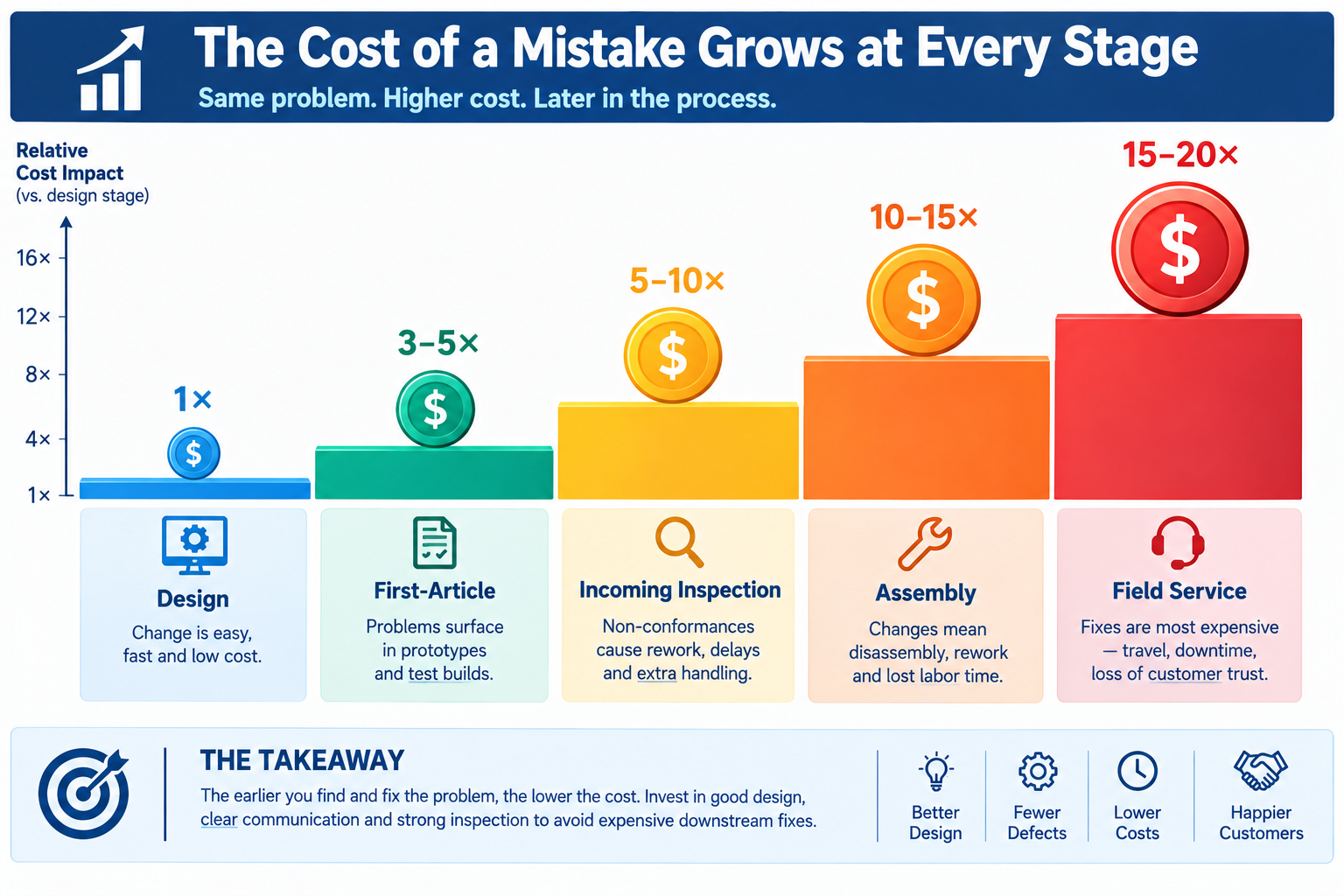
    Bar chart showing GD&T error cost multiplier increasing from 1x at design stage to over 50x at field service

    The GD&T Controls That Carry High-Precision Work

    GD&T defines fourteen geometric controls, but a small subset does most of the work in high-precision industries. These ranges are illustrative starting points, not universal defaults; the correct tolerance for any specific feature comes from that feature’s functional requirement, not a table.

    Control CategoryExample ControlsHigh-Precision ApplicationTypical Tolerance Range
    FormFlatness, circularity, cylindricity, straightnessSeal diameters and bearing journals, where out-of-round shape causes leaks or vibration even within size tolerance0.002-0.02mm
    OrientationPerpendicularity, parallelism, angularityOptical mount faces and gearbox bore axes, where small angular error compounds over distance0.01-0.05mm over 100mm, or 2-10 arc-minutes
    LocationPosition, concentricity, symmetryFastener patterns, wafer alignment pins, mould guide pins, where the zone matches actual functional clearance0.01-0.15mm
    ProfileProfile of a line, profile of a surfaceTurbine aerofoils, optical lens surfaces, body panels, where surface shape itself is the requirement0.02-0.25mm structural; 0.001-0.01mm optical
    RunoutCircular runout, total runoutRotating shafts and spindles, where runout directly determines vibration and bearing life0.005-0.03mm

    Profile Tolerancing: The Control Conventional Dimensioning Cannot Replace

    Profile of a surface deserves particular attention because it’s the one GD&T category with no meaningful conventional-tolerancing equivalent. A turbine aerofoil, an optical lens surface, or a compound-curved body panel can’t be adequately described by linear dimensions to discrete points; the functional requirement is that the entire surface, at every point, stays within a tolerance band of its theoretically exact form. Profile tolerancing defines exactly this: a zone following the true profile at every point, verified today primarily by laser scanning or CMM surface scanning against the nominal CAD model.

    In aerospace and optics work particularly, profile tolerancing isn’t a refinement of conventional dimensioning, it’s the only method that can specify the requirement at all. A drawing describing an aerofoil surface with linear dimensions to a handful of stations either under-specifies the surface between stations or requires an impractical number of dimensions that still wouldn’t guarantee a smooth, aerodynamically valid surface between them.

    Worked Examples

    The semiconductor wafer chuck: A vacuum wafer chuck supplier dimensioned three locating pads by conventional coordinates from the chuck’s outer edge, each with plus/minus 0.008mm tolerance. The chucks passed CMM inspection consistently, but roughly 4% of wafers showed a systematic edge-exposure error during lithography, traced to wafer placement off-centre by up to 0.015mm, larger than the individual pad tolerances should have allowed.

    The three pad positions were each within their individual tolerance relative to the chuck edge, but the scheme didn’t control the pads’ position relative to each other or to a single consistent datum reference frame representing the wafer’s actual centring axis. Three independently toleranced pads, each individually in tolerance, could still combine to shift the wafer’s effective centre by more than any single pad’s tolerance, since the errors weren’t constrained to cancel or bound each other.

    The redesign referenced all three pads to a single datum reference frame built on the chuck’s actual mounting interface, with a true-position tolerance applied to the three-pad pattern as a group, sized to the actual wafer-centring requirement rather than an arbitrary edge-referenced value. This directly constrained what the equipment needed, a consistently centred wafer, instead of an indirect proxy. The edge-exposure error rate dropped from 4% to below 0.1% within the first production lot measured against the new drawing, with no change to the machining process. The pads had been machined to the same physical accuracy throughout; only the tolerancing method defining what accuracy meant had changed.

    The aerospace fastener pattern: An aircraft structural bracket had a 12-hole fastener pattern dimensioned with conventional plus/minus 0.05mm coordinates from a corner datum. The supplier’s CNC process held each hole within 0.02mm of nominal, comfortably inside the drawing tolerance, yet roughly 6% of brackets required hand-reaming during assembly to accept the mating fasteners.

    The plus/minus coordinate dimensioning created independent square tolerance zones for each hole, and the stack-up from the corner datum meant holes furthest from it had larger effective positional uncertainty than the per-hole tolerance implied, since errors in datum-adjacent holes propagated outward through the coordinate chain. The pattern’s actual requirement, that each hole align with its mating structure hole within the fastener’s clearance diameter, was never directly stated, only implied through a chain of independent linear dimensions.

    The redesign applied true-position tolerance directly to each hole relative to a three-datum reference frame on the bracket’s primary mounting features, with an MMC modifier capturing bonus tolerance as each hole’s diameter departed from its minimum size. This directly stated the functional requirement, fastener clearance to the mating structure, instead of an indirect proxy. On the same CNC process capability as before, hand-reaming during assembly dropped to zero, since every hole was now measured directly from the functional datum reference frame rather than accumulated through a coordinate chain.

    Frequently Asked Questions

    Is GD&T only necessary for extremely tight tolerances?

    No. GD&T matters most in high-precision work because the margin for a mismatch is smallest there, but the underlying benefits, an unambiguous datum reference frame, a tolerance zone shape matching the feature’s actual geometry, and bonus tolerance where size and position interact, apply at any tolerance level. Many manufacturers use GD&T on moderate-tolerance parts specifically to reduce inspection disputes and scrap rate even when the tolerance values aren’t extreme. The decision should be driven by whether multiple parties measure the part, whether there’s a genuine assembly-critical function, and whether the feature geometry suits GD&T’s tolerance zone shapes, not by tolerance tightness alone.

    Does adopting GD&T increase manufacturing cost?

    Typically not; in most cases it reduces cost, since a correctly shaped tolerance zone and a bonus-tolerance-capable positional callout give machining and inspection more usable tolerance for the same functional outcome, as shown in the fibre ferrule and aerospace fastener examples. The main cost is the upfront investment in training designers and inspectors and in CMM software capable of evaluating true-position and profile tolerances, an investment normally recovered quickly through reduced scrap and rework at any meaningful production volume.

    Can GD&T and conventional dimensioning be mixed on the same drawing?

    Yes, and most drawings do. Non-functional dimensions, like overall envelope size or reference dimensions for material estimation, are commonly left as conventional dimensions since there’s no assembly-critical function to control precisely. Features with genuine functional relationships to mating parts, fastener holes, mating profiles, bearing bores, sealing diameters, should use GD&T. Apply GD&T wherever a feature’s relationship to another feature or assembly interface actually matters to function, and leave conventional dimensioning where it doesn’t.

    Why do GD&T disputes still happen between suppliers and customers even when both use GD&T correctly?

    The most common cause isn’t incorrect application of GD&T rules but an incomplete or ambiguous datum specification, following the same pattern covered in this series’ companion article on datum selection. GD&T reduces measurement disputes dramatically compared with conventional dimensioning, but doesn’t eliminate them if datum features themselves aren’t clearly and completely defined, for example a datum specified as a general surface rather than a specific area with datum targets. Remaining disputes in a well-executed GD&T programme are almost always resolved by tightening the datum feature definition, not by changing tolerance values.

    What is the single biggest mistake companies make when introducing GD&T?

    Applying GD&T symbols to a drawing without first establishing a functional datum reference frame based on how the part is actually assembled or used. GD&T notation can be mechanically correct, valid feature control frames, valid datum labels, while still failing to deliver its benefit if the chosen datums don’t reflect the part’s real functional relationships. Companies that get the most value treat datum selection as an engineering decision made early in design, informed by how the part will be assembled, machined, and inspected, rather than a drafting task completed after the geometry is finalised.
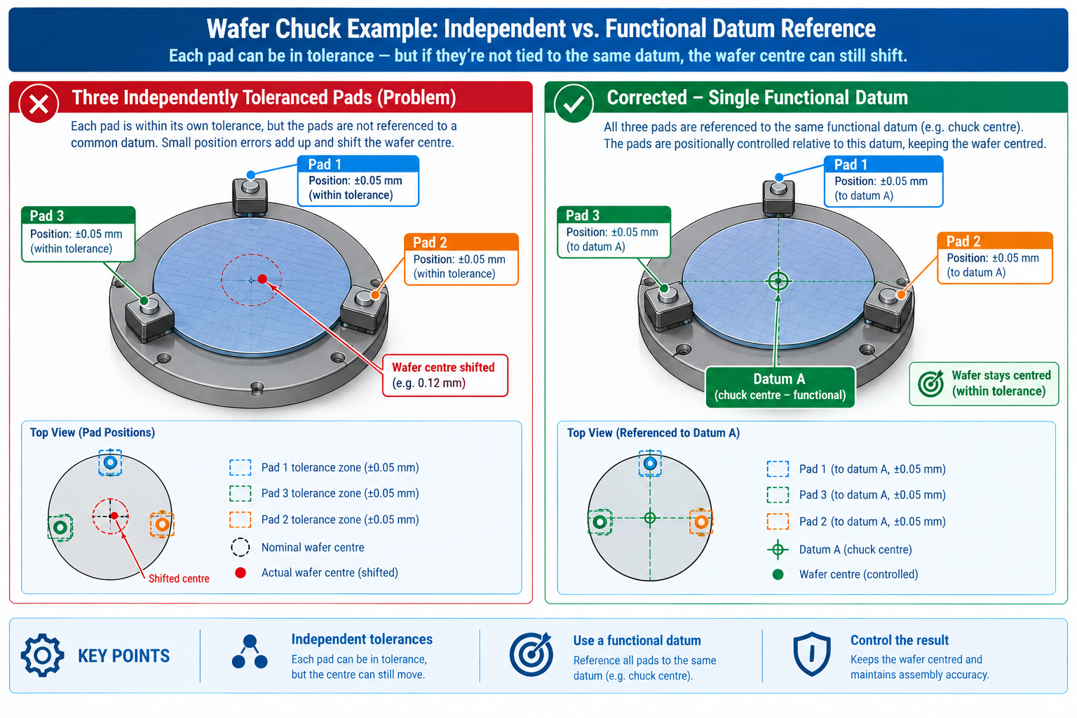
    Diagram comparing three independently toleranced wafer chuck pads causing centring error versus a corrected single-datum reference scheme

    Key Takeaways

    The fibre ferrule manufacturer lost six months of yield to a tolerancing method that didn’t match the geometry of the feature it described. The wafer chuck supplier shipped a 4% edge-exposure defect rate before the root cause traced to a scheme that couldn’t detect a real functional error. The aerospace bracket required hand-rework on 6% of parts that a correctly toleranced drawing would have accepted with no change to machining. None of these failures came from insufficient machining capability. All of them came from a tolerancing language, conventional plus/minus dimensioning, that couldn’t fully and unambiguously describe what the part’s function actually required, following the standards defined in ASME Y14.5 and, for international programmes, ISO 1101.

    GD&T matters in high-precision industries for the same reason a more precise technical vocabulary matters anywhere small differences in meaning carry large consequences: it removes the gap between what a drawing says and what a part needs to do. A circular positional tolerance zone matches a round fastener’s actual clearance. A datum reference frame tied to the assembly interface matches how the part is actually located in service. A profile tolerance describes a curved surface no set of linear dimensions could ever fully specify. In every example here, the manufacturing capability was already sufficient; what was missing was a tolerancing method precise enough to describe the requirement correctly and consistently to every party who would measure the part.

    In industries where a missed micron can mean a failed implant, a misaligned wafer, or a grounded aircraft, that gap between drawing intent and part function isn’t a detail. It’s the difference between a programme that scales reliably and one that spends its margin on rework, disputes, and recalls a correctly applied GD&T scheme would have prevented from the first part off the line.
  • Manufacturing Process Constraints: A Product Designer’s Guide to Choosing the Right Process

    Manufacturing Process Constraints: A Product Designer’s Guide to Choosing the Right Process

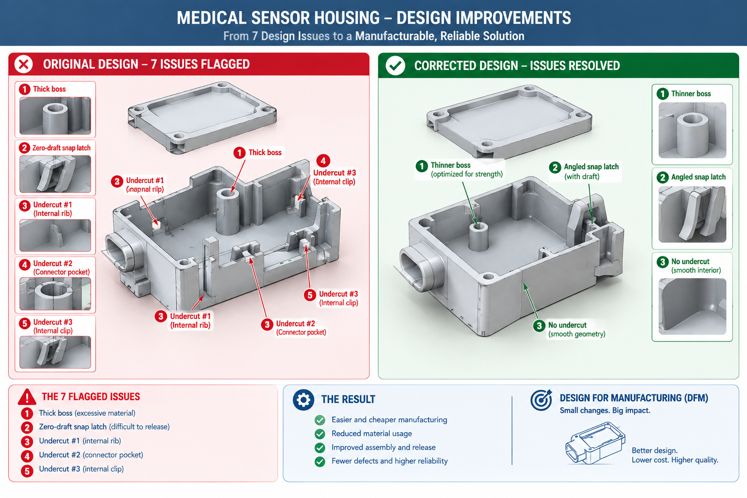
    A product design team spent eight months developing a small medical sensor housing. The design was elegant: organic curves, minimal visible fasteners, integrated cable management, a two-part snap-fit enclosure that felt premium in the hand. Wall thicknesses ranged from 0.9mm at the curved flanges to 4.2mm where the window mounting boss met the shell wall. The snap latches had zero draft, since draft would have complicated the snap face geometry. Three internal undercuts wrapped around the USB port opening.

    The tooling quote came back with seven flagged design issues, four required side actions, and a price more than double the budget. The programme paused for six weeks of redesign, essentially rebuilding what eight months of work had produced, now constrained by rules that had been available at the start but weren’t part of the initial design process.

    Quick answer: Manufacturing constraints exist because every process is bound by physics, molten plastic has to fill a cavity and eject cleanly, a rotating cutting tool can only reach what its geometry allows, sheet metal can only bend as tight as its ductility permits. The single highest-impact decision a product designer makes isn’t a geometric rule at all: it’s choosing the right process for the target production volume before any detailed geometry exists, since that choice determines which constraints apply and what tooling investment gets recovered.
    Medical device housing design comparison showing seven flagged manufacturing issues versus corrected redesign

    This is the scenario manufacturing constraints exist to prevent. The rules aren’t bureaucratic obstacles to creative design. They’re descriptions of what physical processes can and cannot do, most useful when known before a design is finalised rather than discovered when a quote comes back with problems.

    Why Manufacturing Constraints Are Process-Specific

    Every manufacturing process imposes constraints that come directly from its physics. Injection moulding pushes molten plastic into a cavity under pressure, and the plastic has to fill completely and eject cleanly, generating the wall thickness, draft, and undercut rules. CNC machining removes material with a rotating cylindrical tool, and the tool geometry generates the internal corner radius constraint, the pocket depth limit, and the multi-setup cost penalty. Sheet metal forming bends flat material around a tooling radius, and the material’s ductility and springback generate the minimum bend radius and feature-to-bend-line proximity rules.

    None of these constraints are arbitrary; each is a physical consequence of how the process works. A designer who understands the physics behind two or three constraints tends to figure out related ones without looking them up, since the same underlying mechanism generates multiple related rules. Understanding that injection moulded walls need draft because the part shrinks onto the core as it cools and has to slide off the steel without tearing is more durable knowledge than memorising “1 degree per side,” since the physical understanding generates the correct angle for any texture depth without a table lookup.

    Understanding the mechanism also clarifies when a constraint applies at all. Draft on a flat horizontal face parallel to the mould opening direction is irrelevant, since that face never slides across the mould steel during ejection. Draft on a vertical face is essential, since that face slides along the steel for the entire ejection stroke. Knowing why makes it immediately clear which surfaces need draft and which don’t.

    Ten Processes, Their Constraints, and Their Sweet Spots

    This comparison helps with the earliest and most consequential decision in product development: which process fits this part, at this volume, with these material and performance requirements.

    ProcessMin Feature SizeTypical ToleranceVolume Sweet SpotKey Constraint
    Injection moulding0.4mm features; 0.8mm min wall+/-0.1 to 0.25mm10,000 to millionsUniform wall thickness (within 15%); draft on all vertical faces; no undercuts without side actions
    CNC milling0.5mm end mill; 1mm practical+/-0.025 to 0.1mm1 to 1,000Internal corners always carry a radius; pocket depth max 4x width; each setup adds 20-40% cost
    CNC turning0.1mm feature detail+/-0.01 to 0.05mm1 to 10,000Features must be rotationally symmetric; off-axis holes need a separate milling setup
    Sheet metal (press brake)1mm hole (punched); 0.5mm laser+/-0.5-1.0mm bent; +/-0.1mm flat10 to 100,000Holes distort within 2.5x thickness of a bend; springback must be designed in
    Die casting (aluminium)0.8mm wall; 0.4mm HPDC+/-0.1 to 0.3mm5,000 to millionsDraft required (1-3°); undercuts need slides; porosity risk in thick sections
    Sand casting5mm wall; 3mm with chill+/-0.5 to 2.0mm1 to 500Large draft required (2-5° per side); generous internal corner radii; core prints needed
    ForgingComplex 3D; limited thin sections+/-0.5 to 2.0mm500 to millionsFlash line runs along the parting plane; cannot form internal cavities without machining
    3D printing (FDM/SLS/SLA)0.1-0.4mm+/-0.1 to 0.3mm1 to 500Anisotropic strength (weakest across layers); supports needed for overhangs > 45°
    Laser cutting (flat)0.1mm kerf+/-0.05 to 0.1mm1 to any volume2D only; slight edge taper at high thickness; dross removal on thick cuts
    Waterjet cutting (flat)0.5mm after kerf+/-0.1 to 0.25mm1 to moderate2D only; no heat-affected zone; slower than laser or plasma for thick material

    Volume and Process Selection: The Tooling Cost Trade-off

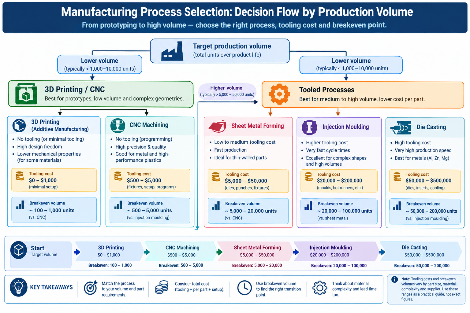
    The most consequential decision a product designer makes, before any geometry is finalised, is which process to use at which production volume. This decision determines tooling investment, achievable unit cost, available tolerances and finishes, and the constraints the design must satisfy. Getting this right early is far more valuable than optimising within a process chosen without weighing whether it fits the volume.

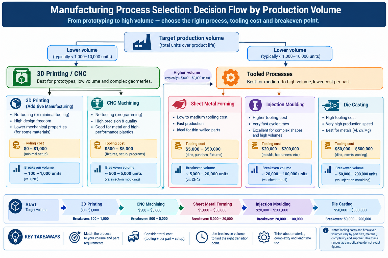
    The fundamental trade-off is between tooling investment and unit cost. Tooled processes (injection moulding, die casting, progressive stamping) carry high fixed costs but low per-part variable cost once tooling is paid off. Toolless processes (CNC machining, 3D printing, laser cutting) carry no fixed cost but higher variable cost per part, since each part needs fresh machine time. The crossover point, where total tooled-process cost drops below total toolless-process cost at the same volume, is the volume breakeven.

    Production VolumeTypically Correct ProcessTooling Cost RangeUnit Cost RangeLead Time to First Parts
    1-5 units (proof of concept)3D printing; CNC for structural prototypesNone or minimal$20-$500 per part1-5 days print; 5-15 days CNC
    5-100 units (pilot/pre-series)CNC machining; 3D printing; sheet metal$0 CNC; $500-5,000 soft-tool mould$50-$2,000 per part5-15 days CNC; 4-8 weeks soft tool
    100-1,000 unitsCNC if complex; sheet metal; die casting if geometry suits$5,000-$80,000 for tooled processes$10-$200 machined; $3-$30 cast6-14 weeks tooled
    1,000-10,000 unitsInjection moulding; aluminium die casting; sheet metal$15,000-$200,000$1-$20 injection moulded; $3-$50 die cast8-16 weeks tooling
    10,000-100,000 unitsInjection moulding; die casting; progressive die sheet metal$50,000-$500,000$0.10-$5 per part12-24 weeks tooling
    100,000+ units (mass production)Injection moulding; die casting; progressive stamping; hot stamping$200,000-$2,000,000$0.02-$2 per part24-52 weeks major tooling

    The Breakeven Calculation: Simple But Often Skipped

    The calculation is straightforward: total cost of a tooled process is tooling cost plus unit cost times volume. Total cost of a toolless process is unit cost times volume. Breakeven volume equals tooling cost divided by the unit cost difference between the two processes.

    For a plastic part costing $8 per unit by CNC machining and $0.50 per unit by injection moulding, with a $40,000 tooling investment: breakeven volume = $40,000 / ($8 – $0.50) = $40,000 / $7.50 = 5,333 units. Below that, CNC is cheaper overall. Above it, injection moulding is cheaper overall.

    This calculation is rarely wrong in direction, and it’s almost never done at the point where the process decision actually gets made. Teams commit to injection moulding because “it will be a consumer product” without checking whether the target volume crosses the breakeven, or they commit to CNC because “it’s a prototype” without realising the actual pilot volume already sits above the point where moulding would be cheaper over the programme lifetime. The calculation takes fifteen minutes and changes the decision more often than most designers expect.

    Material-Process Compatibility: The Constraints Before the Constraints

    Before any geometric design constraint applies, there’s a more fundamental question: is this material compatible with this process at all? Not all materials can be processed by all processes, and combinations that look plausible in theory can be impractical or extremely expensive in reality.

    MaterialInjection MouldingCNC MachiningSheet Metal FormingDie CastingKey Constraint
    Aluminium alloysNot applicableExcellentGood (5052, 3003); difficult (6061-T6)Excellent, primary process6061-T6 needs annealing for tight bends; die cast alloys (A380) differ from wrought
    Mild steelNot applicableGoodExcellent, standard materialNot typicalWeld distortion in thin gauge; scale/rust needs coating
    Stainless steelNot applicableDifficult (work-hardening)Moderate; higher springbackNot common303 free-machining grade avoids work-hardening issues
    Engineering thermoplasticsExcellent, primary processGood (Delrin/POM best)Not applicableNot applicableSome plastics absorb moisture, affecting post-mould dimensions
    Copper and brassNot applicableExcellent (brass); good (copper)Good at annealed temperPossible, not commonGalvanic corrosion risk with steel fasteners
    Titanium alloysNot applicableDifficult, expensiveVery limitedNot practicalCost driven by tool life and cutting time
    High-performance polymers (PEEK, PTFE)Possible with high-temp toolingGood (PEEK); care needed (PTFE)Not applicableNot applicablePEEK injection moulding needs 150-200°C tool temperatures
    Elastomers (silicone, TPU)LSR moulding; TPU injection mouldedLimited, soft materials deflectNot applicableNot applicableLSR requires dedicated tooling separate from thermoplastic tooling

    The Cost of Getting Material-Process Compatibility Wrong

    Some mismatches are obvious, specifying stainless steel for injection moulding is clearly wrong since one’s a metal and the other’s a plastics process. The more dangerous mismatches are plausible in principle but problematic in practice: specifying 6061-T6 aluminium for die casting (the wrong alloy family, which uses A380 or A360), specifying glass-filled nylon for a part that needs adhesive bonding (glass fill significantly reduces bond strength), or specifying PEEK for injection moulding without accounting for the $200,000 to $500,000 cost of a high-temperature tool.

    The habit that prevents these problems is checking material-process compatibility as one of the first steps of design, not as a review after the design is complete. A five-minute conversation with a supplier who specialises in the target process, asking whether the specified material is standard for their process, catches these issues at zero cost, following the process capability principles documented in Kalpakjian and Schmid’s Manufacturing Engineering and Technology. The same discovery after a drawing release and a tooling quote takes weeks to resolve.

    Twelve Universal Manufacturing Constraints

    Beyond the process-specific rules in the companion articles of this series, these twelve constraints apply across multiple processes and are worth carrying as working knowledge.

    ConstraintRule of ThumbApplies ToWhat Breaks If Ignored
    Wall thickness uniformityKeep variation within 10-15% of nominalInjection moulding, die casting, thermoformingSink marks, warping, voids, scrap on first shots
    Draft angle on vertical faces1-2° minimum; add 1° per 0.025mm texture depthInjection moulding, die casting, forgingPart sticks in mould; drag marks; tool damage
    Internal corner radiusMinimum 1x wall thickness; match standard tool sizesCNC milling, injection moulding, die castingStress concentration; custom tooling required
    Undercut/side actionAvoid unless volume justifies tooling costInjection moulding, die casting, forgingSlides/lifters add 20-50% tooling cost
    Feature-to-bend-line proximityHoles at least 2.5x thickness + bend radius from bend lineSheet metal formingFeatures distort; holes become ovals
    Minimum flange length3x thickness + inside bend radiusSheet metal press brake bendingInaccurate, inconsistent bend angle
    Pocket depth-to-width ratioMaximum 4:1 with standard toolingCNC millingTool deflection, chatter, possible breakage
    Tolerance vs. process capabilityCommercial tolerance needs no special process; each tighter step adds 1.5-6x costAll machined/formed processesOver-tolerancing adds cost with no functional benefit
    Part count in assembliesAsk “can this be one part?” before adding a secondAll assembly designsUnnecessary assembly time, inventory, failure points
    Springback in bendingDesign the bend angle to compensate; document itSheet metal, roll forming, tube bendingPart springs to wrong angle; assembly interference
    Material-process compatibilityCheck compatibility earlyAll processesWrong material for the process; late-stage redesign
    Tooling investment vs. volume breakevenCalculate cost per part at target volume including amortisationInjection moulding, die casting, progressive stampingTooling spend never recovered at actual production volume

    Part Count: The Constraint That Compounds Across the Entire Product

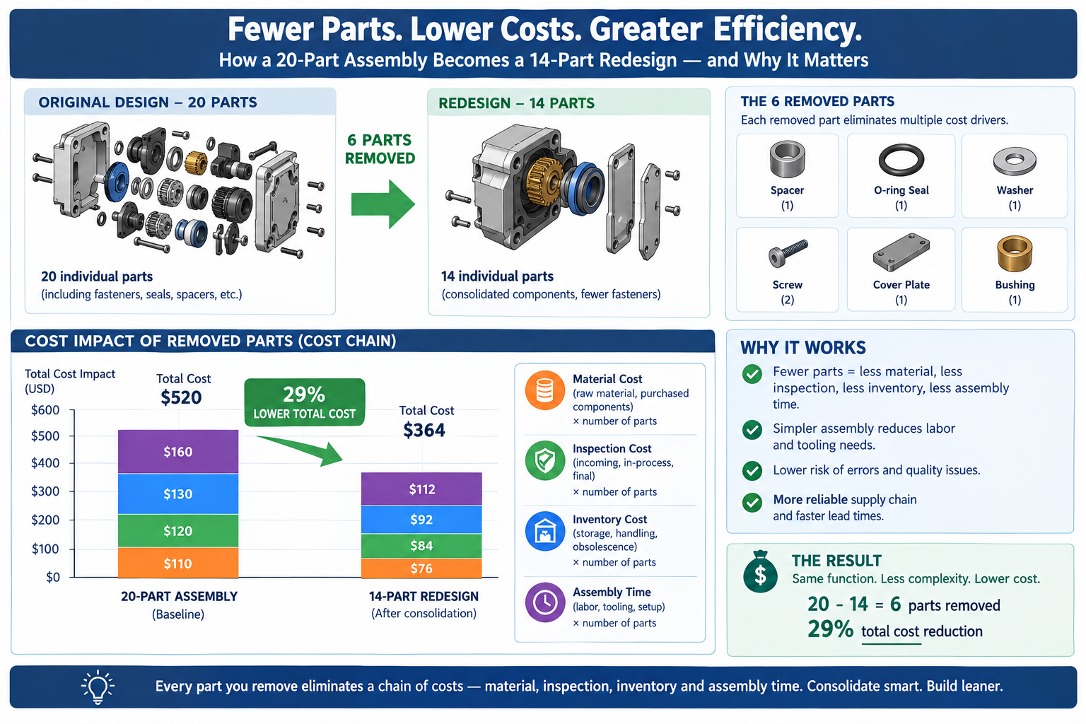
    Of these twelve, part count reduction has the largest potential impact and is the most frequently overlooked, precisely because it’s not a feature-level constraint. It applies to the whole assembly, requiring a step back from individual part optimisation to ask whether the assembly could be simplified.

    Each separate part carries its own cost chain: material, machining or forming, quality inspection, supplier management, inventory, picking during assembly, and any fasteners used to join it. Consolidating two parts into one eliminates most of that chain for the second part, on every unit produced. The savings aren’t dramatic for a small two-part assembly with limited volume. They become significant for a twenty-part assembly at a hundred thousand units per year, where the difference between twenty parts and fourteen means six fewer cost chains multiplied across a hundred thousand units.

    The systematic question, drawn from the Boothroyd-Dewhurst design for assembly criterion, is: does this part move relative to adjacent parts, does it need a different material, and does it need to be disassembled for service? If the answer to all three is no, there’s a good case for consolidating it into a single feature on an adjacent piece.

    Comparison diagram showing cost chain reduction from consolidating a twenty-part assembly into fourteen parts

    When Manufacturing Constraints Are Discovered Determines Their Cost

    Every constraint not considered during design gets discovered eventually: by the product designer in a review, the mould maker in a quote, the operator at the press brake, or the inspector at the quality station. The cost of resolving it grows by roughly an order of magnitude at each successive stage. A wall thickness problem caught in design review costs an hour of CAD time. The same problem caught after tooling is cut costs tool rework, schedule delay, and possibly scrapped first-article parts, together perhaps a hundred times the design review fix.

    This asymmetry is the entire business case for knowing manufacturing constraints at the design stage rather than learning them from supplier feedback. The knowledge itself is free. The cost is in when it’s applied, and it’s minimised the earlier it’s applied.

    The Design Review as a Manufacturing Constraint Check

    The most practical institutional way to apply constraints early is a structured design review focused specifically on manufacturability, distinct from the structural and functional reviews that happen as a matter of course. A manufacturing-focused review asks a different question, not “will this carry the load” but “can this be made, at this volume, with the process specified, by a supplier with reasonable capability for these features.” These are engineering questions that need manufacturing knowledge to answer, whether from a manufacturing engineer, a supplier representative, or a designer who has studied the process-specific guidelines this series covers.

    The twelve-item table above is one framework for structuring that review: a checklist workable in thirty to sixty minutes for a typical design, checking each part against the constraints for its intended process. None of the checks need specialised equipment. They need knowing what to look for while the design is still on screen.

    Worked Examples

    The medical sensor housing: The housing from the opening example, eight months in design before the tooling quote revealed seven problems, could have caught all of them with a constraint checklist during design. The wall thickness variation from 0.9mm to 4.2mm was far outside the 10-15% rule; the 4.2mm boss should have been redesigned to 60% of the adjacent wall with a gusset rib. Zero draft on the snap faces meant the part couldn’t eject without surface damage; a minimum one degree on the non-functional face would have worked without compromising the snap function.

    The three USB port undercuts could have been redesigned as through-features formed by two mould halves at the parting surface, or repositioned to allow core pull in the mould opening direction.

    The tools to catch these issues, wall thickness analysis, draft analysis, and a pull-direction undercut check, were standard features in the CAD package used from day one. Eight months of design could have been eight months of constraint-aware design instead. The six weeks of post-quote redesign was time lost entirely.

    The enclosure that should have been sheet metal, not machined: An industrial instrument enclosure was designed as a machined aluminium block with milled pockets for internal electronics, needing four setups and several precision tolerances on PCB mounting bosses. At an estimated $320 per unit for a target run of 800 units, total machined cost was $256,000.

    A volume breakeven check against sheet metal told a different story. A press brake-formed, laser-cut version with PEM-nut fastener inserts for PCB mounting had an estimated unit cost of $45, with no tooling investment for the standard sizes involved. At 800 units, total sheet metal cost was $36,000. The IP54 weatherproof rating, 0.2mm PCB mounting positional accuracy, and hard-anodised finish requirements were all achievable in sheet metal with appropriate gasket design and CMM-checked PEM nut locations. The switch saved roughly $220,000 on this run while meeting every functional requirement.

    The machined option hadn’t been obviously wrong at the concept stage; it was chosen because the team was comfortable with machined enclosures and never evaluated the sheet metal alternative. The thirty-minute breakeven check made the comparison explicit and changed the decision. The constraint that unlocked the saving wasn’t a geometric rule. It was process selection based on volume.

    Frequently Asked Questions

    How early in the design process should manufacturing constraints be considered? From the first sketch. The most consequential decisions, which process and which material, are made or implied before any geometry exists, at the concept stage where product category and approximate volume are first established. A consumer product at high volume implies injection moulding, which implies thermoplastics, which implies wall thickness uniformity, draft, and every other injection moulding rule, all before a single wall is modelled in CAD. Confirm the process-versus-volume decision before detailed design begins, not after a tooling quote reveals it was wrong.

    What is the most important manufacturing constraint for a designer working across multiple processes? Wall thickness uniformity in moulded and cast parts is probably the most impactful geometric rule, since violations are both common and highly visible: sink marks on a cosmetic surface are exactly the defect customers notice. But the constraint with the largest programme-level impact is the volume breakeven calculation, since choosing the wrong process for a given volume doesn’t just create a bad part, it creates bad product economics, which is much harder to fix than a sink mark.

    Can 3D printing replace injection moulding for production parts? For some applications and volumes, yes. Industrial processes like SLS, MJF, and DMLS produce functional parts in engineering-grade materials at tolerances competitive with injection moulding for low to moderate volumes. The practical limits are unit cost (higher than moulding above roughly 500 to 1,000 units for most sizes), a narrower material range, and surface finish showing layer lines unless post-processed. For volumes below a few hundred units, complex geometries that would need expensive tooling, or evolving designs, 3D printing is often the better choice. Above a few thousand units in a stable design, injection moulding is almost always lower total cost.

    What does “design for manufacture” actually mean in practice? It means applying knowledge of how each process works to the design decisions made at the CAD stage, so the resulting part is producible by the chosen process, at the intended cost, without surprises at tooling or fabrication. It’s not a separate analysis step added at the end. It’s a way of thinking about geometry integrated into how the design is built, asking “can a tool reach this corner,” “will this wall cause a sink mark,” “do these holes move when this face bends” throughout modelling rather than after it.

    How do I know which manufacturing process to specify for a new product? Start with production volume and unit cost target, since these determine which processes are economically viable. At a few hundred units, CNC machining and sheet metal are typically the only practical metal choices, with 3D printing or soft-tool moulding for plastics. At tens of thousands, injection moulding and die casting become cost-competitive. At hundreds of thousands, progressive stamping and other high-volume processes fit. Within the economically viable options, check material-process compatibility, then check whether functional requirements are achievable. If multiple processes clear all three bars, choose based on team experience or the strongest local supplier base.

    Why does adding a side action to an injection mould add so much cost? A side action is a moving mechanism inside the mould that travels perpendicular to the opening direction to form an undercut, requiring precision-machined steel, guide rails, locking mechanisms, and return springs. Each slide needs its own design, machining, fitting, and debugging. A simple slide might add 15 to 25 percent to tooling cost; a complex compound-motion slide might add 40 to 60 percent. Three or four slides, as in the medical housing example, can more than double tooling cost relative to an undercut-free design, which is why the rule is to eliminate undercuts where possible and budget explicitly when they’re genuinely necessary.

    Manufacturing process selection flowchart based on production volume and tooling cost breakeven points

    Key Takeaways

    The sensor housing that took six weeks to redesign, and the instrument enclosure that could have been sheet metal all along, share the same underlying issue: the constraints that would have changed the design decisions were available but weren’t part of the conversation at the right time. None of this is specialised knowledge requiring years of manufacturing experience. It’s available in published guidelines, supplier conversations, and process-specific references.

    The shift that makes manufacturing constraints useful rather than frustrating is treating them as information about what a process does well, not restrictions on what a designer can create. Injection moulding produces thin, uniform walls with complex geometry and integrated features at tolerances machining can’t match at scale, as long as the design respects what the process needs. CNC machining produces any machinable geometry to tight tolerances without tooling investment, as long as the design respects what a cutting tool can reach. Sheet metal produces lightweight, strong enclosures cheaply at almost any volume, as long as the design respects how the material bends.

    Every process constraint is a description of what that process does well, stated as a boundary condition. Designers who understand that, who know enough about several processes to design for them deliberately rather than discovering the limits from suppliers, get from first quote to first production more smoothly, more cheaply, and with fewer detours.