The Problem: Your Design and Simulation Stages Are Still Disconnected
Here’s a situation most mechanical engineers know well. You finish a CAD model, export the geometry, hand it to a simulation analyst (or switch tools yourself), spend half a day setting up the mesh and boundary conditions, run the solver overnight, get results that point to a design change, and then go back to the beginning.
That cycle, design, export, setup, simulate, revise, is slow. It was designed for a world where simulation was expensive and rare. But in 2026, simulation tools are faster and AI is everywhere. The bottleneck isn’t the solver anymore. It’s the AI CAD pipeline connecting everything together.
What engineers actually need is an AI-driven engineering pipeline, a connected sequence of intelligent tools and prompts that carries a design from concept through CAD modelling, FEA or CFD setup, results interpretation, and documentation without the constant manual handoffs that kill momentum.
That’s exactly what this guide builds. Step by step. With real prompts you can use today.
| 3 hrs/daysaved on average | Industry benchmarks for 2026 show that integrating AI into the CAD-to-simulation workflow saves engineers an average of 3 hours per day, reclaimed from manual data extraction, repetitive setup, and documentation (Energent.ai, 2026). |
| 94.4% AI accuracy | Leading AI data agents now achieve up to 94.4% accuracy when reading complex unstructured engineering documents and schematics, dramatically reducing downstream specification errors. |
What an AI Pipeline for CAD and Simulation Actually Looks Like
Before building one, it helps to have a clear mental model. An AI pipeline for CAD and simulation is not a single tool, it’s a chain of connected AI interactions, each stage feeding the next with better, more specific information.
Think of it like a relay race. The first runner (your LLM for engineering design) carries the design intent. The second (your CAD tool or text-to-CAD platform) turns that intent into geometry. The third (your FEA or CFD solver with AI setup) validates the geometry against physics. The fourth (your AI interpretation layer) tells you what the results mean and what to change. The baton never drops. The pipeline keeps moving.
What makes this different from just ‘using AI tools’ is the prompt-based CAD workflow that threads through every stage. Prompts aren’t just for chatting, they’re the connective tissue of the pipeline. The right prompt at each stage ensures the output of one tool becomes a clean, usable input for the next. That’s what CAD simulation using prompts actually means in practice.
The Four Roles Prompts Play in the Pipeline
Understanding how prompts function at each stage clarifies why prompt engineering for design and simulation is worth learning deliberately, not just picking up informally.
- Prompt as brief: At the design stage, a structured prompt is your engineering requirements document, it captures loads, materials, constraints, and manufacturing intent in a format AI tools can act on directly.
- Prompt as translator: Between CAD and simulation, a prompt converts geometry decisions into AI prompts for FEA and simulation, boundary conditions, mesh guidance, load cases, and solver settings expressed in clear language.
- Prompt as analyst: After simulation, a prompt frames your results for AI interpretation, ‘This stress concentration is at the fillet. What does that indicate and what geometry change would address it?’
- Prompt as documenter: At the close of the pipeline, a prompt generates technical reports, design summaries, and revision notes automatically, closing the AI design loop cleanly.
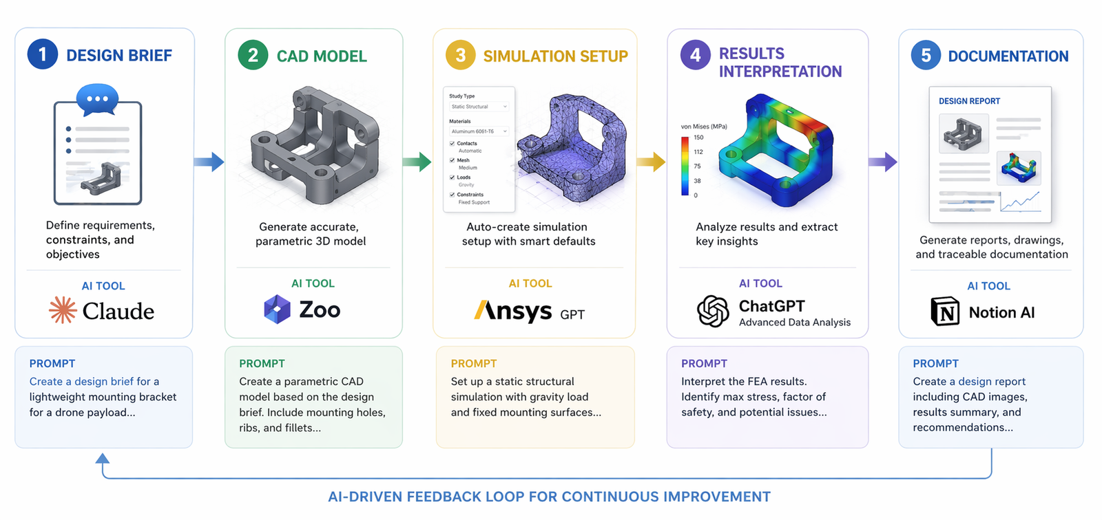
How to Build an AI CAD Simulation Pipeline, The 5 Stages
Here is how to build a working AI pipeline for CAD and simulation using prompts. Each stage includes the tool stack, the prompt structure, and what to hand forward to the next stage. These aren’t theoretical, they’re the practices that effective AI simulation workflow teams are using in 2026.
| 1. Design Brief, Define Intent Before You Touch the Software Most pipeline failures start here. Engineers open CAD immediately and start modelling before the requirements are precise. An AI-driven pipeline starts with a structured brief that captures everything the downstream stages need: geometry constraints, loads, materials, manufacturing method, and success criteria. Prompt, Stage 1 Design Brief (use with Claude AI): “You are a senior mechanical engineer. I need to design [part description]. Loads: [specify]. Material: [specify]. Manufacturing: [specify, e.g. CNC aluminium]. Key constraints: [tolerances, fits, standards]. Output a structured engineering brief with: (1) critical dimensions to define, (2) primary failure modes to simulate, (3) recommended simulation type (FEA/CFD/thermal), (4) suggested boundary conditions.” Keywords active: Claude AI engineering prompts · LLM for engineering design · prompt-based CAD workflow |
| 2. CAD Modelling, Geometry From Your Brief Take your Stage 1 brief directly into your CAD or text-to-CAD tool. The brief is already formatted in the way AI geometry tools work best: specific, dimensioned, and constraint-aware. This is where connecting CAD to simulation with AI begins, the model you build now must be simulation-ready from the start. Prompt, Stage 2 CAD Model (use with Zoo, AdamCAD, or SolidWorks + Claude): Based on this engineering brief: [paste brief from Stage 1]. Generate a [STEP / parametric feature list / AutoLISP script] for this part. Ensure all simulation-critical features, fillets, contact surfaces, load application areas, are explicitly defined. Flag any geometry that may require simplification before meshing.” Keywords active: connecting CAD to simulation with AI · Zoo text-to-CAD pipeline · CAD AI prompts |
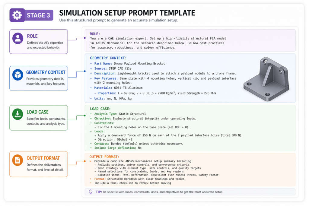
| 3. Simulation Setup, The Bridge Most Engineers Get Wrong This is the stage where most manual pipelines collapse. Moving a CAD model into FEA or CFD correctly requires specialist knowledge of meshing, boundary conditions, and solver settings. AI FEA automation now handles the bulk of this, but only if you feed it well-structured prompts. Prompt, Stage 3 Simulation Setup (use with SimScale AI, Ansys, or Claude for setup notes): “I have a [material + geometry description] part. Load case: [describe loads and constraints]. I need to set up a [static structural / modal / CFD] simulation. Output: (1) recommended mesh density at critical features, (2) boundary condition checklist, (3) material properties to confirm, (4) expected failure modes to monitor in post-processing, (5) convergence criteria.” Keywords active: AI prompts for FEA and simulation · CAD to FEA automation · Ansys SimAI pipeline |
| 4. Results Interpretation, From Numbers to Engineering Decisions Raw simulation output, stress plots, displacement fields, pressure distributions, is information, not insight. This is where the AI interpretation layer converts numbers into engineering decisions. The prompt structures your results in a way that surfaces the most important findings and recommends specific design changes. Prompt, Stage 4 Results Interpretation (use with Claude AI): “I have run a static FEA on a [part description]. Results: maximum von Mises stress = [X] MPa at [location], material yield = [Y] MPa, safety factor = [Z]. Displacement at load point = [A] mm. Tell me: (1) Is this design safe? (2) What is driving the peak stress, geometry or boundary conditions? (3) What are the top 2 design changes I should model next? (4) Are there any non-obvious failure modes I should check?” Keywords active: AI-powered design validation · automated simulation pipeline · AI design loop |
| 4. Documentation, Closing the Pipeline Cleanly The last stage is where most AI pipelines leak value. Engineers interpret their results, make design changes, and move on, without recording the engineering rationale. A single prompt closes this gap and produces documentation that serves revision history, client reporting, and team knowledge transfer simultaneously. Prompt, Stage 5 Documentation (use with Claude AI): “Based on this design and simulation session: [paste summary of design brief, model choices, simulation results, and decisions made]. Write a structured engineering design note covering: (1) Design intent and requirements, (2) Key modelling decisions and rationale, (3) Simulation summary and findings, (4) Design changes implemented and why, (5) Open items and recommended next steps. Format for inclusion in a technical design review package.” Keywords active: prompt-to-simulation workflow · AI-driven engineering pipeline · AI simulation workflow |
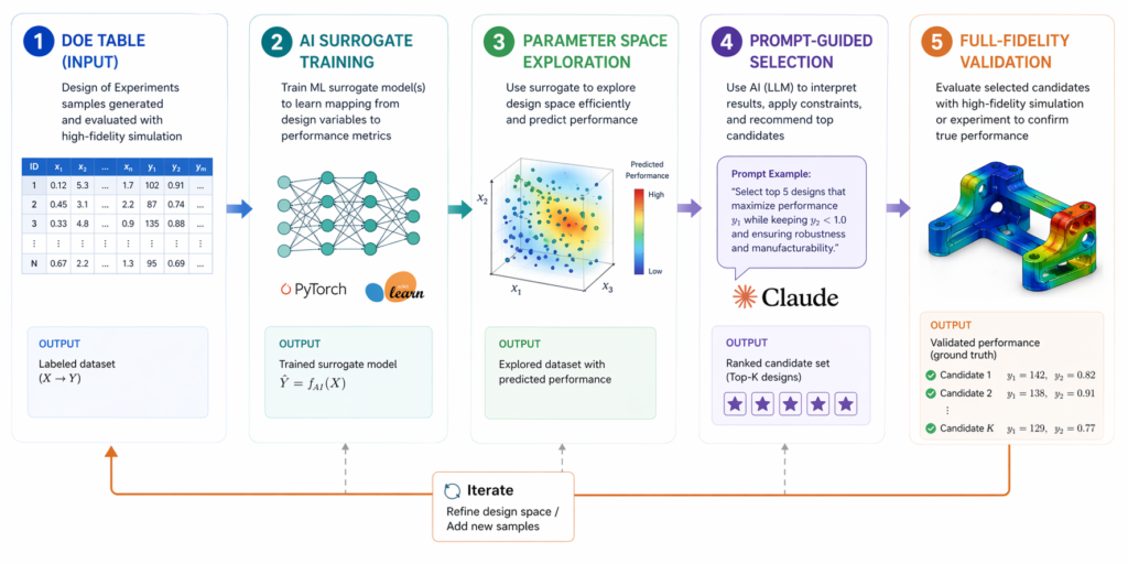
Going Further: The Surrogate-Driven Design Loop
Once you have the basic five-stage pipeline working, the next level is the surrogate-driven design loop. This is where the AI pipeline for CAD and simulation becomes genuinely autonomous in the optimisation stage, running tens or hundreds of design variants without human intervention between each one.
What a Surrogate-Driven Loop Actually Is
A surrogate model is a lightweight AI trained on your simulation results. Instead of running the full solver for every new design variant, the surrogate predicts the outcome in milliseconds. You explore the parameter space, wall thickness, fillet radius, hole placement, across 50 or 100 points, then run full-fidelity AI-powered CAE simulations only on the most promising candidates.
Research published on arXiv (July 20251) demonstrated that LLMs can convert natural-language descriptions into valid CAD command sequences, essentially ‘prompt-to-feature-tree.’ When combined with surrogate-speed predictions, this creates a prompt-to-simulation workflow that is genuinely new, not just faster, but architecturally different from any previous engineering process.
Practical Surrogate Loop Using Prompts
- Define your parameter space with a prompt: ‘I want to optimise a bracket for minimum weight with a safety factor ≥ 3. Variables: wall thickness 3–8mm, fillet radius 2–6mm, rib height 0–12mm. Generate a 25-point design of experiments (DOE) table spanning these ranges.’
- Run initial simulations: Feed the DOE table into your Ansys SimAI pipeline or SimScale. Run all 25 variants, this takes hours, not days, with AI-accelerated solvers.
- Build the surrogate: Use the 25 results to train a lightweight surrogate. Tools like Altair HyperWorks and Monolith AI handle this automatically. Your surrogate-driven design loop is now active.
- Explore with prompts: Ask Claude: ‘Based on these surrogate predictions, which 3 design points offer the best weight-to-safety-factor trade-off? What would happen if I increased the rib height by 2mm at those points?’ Use AI interpretation to guide the next round.
- Validate the winner: Run one full AI-powered CAE simulation on your selected design. Document with Stage 5 prompt. Pipeline complete.
The Tool Stack That Powers This Pipeline
You don’t need all of these tools on day one. Build the pipeline incrementally, starting with the prompt layer and adding specialist tools as your team grows into them. Here’s how the stack fits together for a complete AI-driven engineering pipeline:
| Pipeline Stage | Tool(s) | AI Role | Prompt Use |
| Stage 1, Brief | Claude AI | LLM for engineering design | Requirements → structured brief |
| Stage 2, CAD | Zoo / AdamCAD / SolidWorks | Zoo text-to-CAD pipeline | Brief → geometry prompt |
| Stage 3, Sim Setup | SimScale AI / Ansys | Ansys SimAI pipeline | Brief + model → boundary conditions |
| Stage 4, Interpret | Claude AI | AI-powered design validation | Results → engineering decisions |
| Stage 5, Docs | Claude AI | prompt-to-simulation workflow | Session → design note |
| Optimisation Loop | Altair / Monolith AI | surrogate-driven design loop | DOE → surrogate → prompt queries |
A note on tool choice: Claude AI engineering prompts are the unifying thread across all five stages. Claude handles design briefs, prompt refinement, results interpretation, and documentation, making it the single most versatile tool in the AI CAD pipeline. Specialist tools (Zoo for geometry, SimScale or Ansys for physics) handle what Claude can’t: actual geometry generation and physics solving. Together, they form a complete automated simulation pipeline.
Making the Pipeline Stick: Practical Guidance for Engineering Teams
An AI pipeline for CAD and simulation is only valuable if it actually gets used. Here’s what separates teams who build a lasting AI-driven engineering pipeline from those who run one project and revert to old habits.
Build a Prompt Library, Not Just Skills
Individual prompt skills don’t scale. What scales is a shared prompt library, a documented set of tested, refined prompts for each stage of the prompt-based CAD workflow. Every time someone writes a prompt that produces an excellent output, that prompt goes into the library. Within six months, the library becomes the team’s most valuable AI asset.
Organise it by stage and part type: Stage 1 briefs for brackets, housings, and pressure vessels. Stage 3 AI prompts for FEA and simulation for static structural, modal, and thermal studies. The prompt-to-simulation workflow becomes systematic, not tribal.
Start With One Bottleneck
Don’t try to deploy all five stages at once. Identify your team’s single biggest time sink, typically Stage 3 (simulation setup) or Stage 5 (documentation), and build the pipeline around that first. A team that reduces CAD to FEA automation setup time by 60% on one project type will have all the internal buy-in needed to expand the pipeline further.
Validate Ruthlessly at Every Stage
The AI simulation workflow must include validation checkpoints. Every Stage 3 setup should be reviewed against a checklist before the solver runs. Every Stage 4 interpretation should be confirmed by a qualified engineer before becoming a design decision. AI-powered design validation accelerates the process, it doesn’t replace the judgement that keeps your products safe.
Use the Surrogate Loop for Design Families, Not One-Offs
The surrogate-driven design loop is most powerful when applied to repeating design families, a family of brackets, a set of housing geometries, a series of pressure vessel variants. Building one surrogate for a design family and reusing it across multiple projects multiplies the ROI dramatically. The first project absorbs the setup cost; every subsequent project runs on near-instant predictions.
What an Excellent AI Pipeline Looks Like in Practice
Let’s make this concrete. Below is how a complete CAD simulation using prompts session plays out for a real engineering task, designing and validating a structural mounting bracket, using the five-stage pipeline.
Complete Pipeline Example: Steel Mounting Bracket
Part: Steel mounting bracket for industrial conveyor motor (2kN steady-state + 500N peak dynamic load)
Material: S275 structural steel, CNC machined
Standard: ISO 2768 medium tolerance, safety factor ≥ 3
Stage 1 prompt:
“You are a senior mechanical engineer. I need to design a CNC steel mounting bracket for a 45kg conveyor motor. Loads: 2kN static vertical, 500N horizontal dynamic. Material: S275 steel, 5mm minimum wall. Fixed to machine frame via 4 × M10 bolts. ISO 2768 medium. Output a structured brief with critical dimensions, failure modes to simulate, and recommended FEA boundary conditions.”
What Claude returns:
A fully structured design brief: 3 critical geometry dimensions with recommended ranges, 4 failure modes ranked by likelihood, meshing guidance, boundary condition checklist, and a FEA load case matrix, ready to use as the Stage 2 and Stage 3 inputs.
Stage 4 interpretation prompt (after FEA run):
“Max von Mises: 187 MPa at inside fillet radius on primary leg. S275 yield: 275 MPa. Safety factor: 1.47. This fails my ≥3 SF requirement. Displacement at motor mount: 0.8mm. What is driving the stress, fillet radius or wall thickness? What is the minimum wall change to meet SF ≥ 3?”
Claude identifies the fillet radius as the primary driver, recommends increasing the fillet from 3mm to 8mm as the highest-impact change (reducing peak stress 35–40% based on standard stress concentration data), and suggests a secondary wall increase from 5mm to 6mm as insurance. Total time for Stage 4: 4 minutes.
Conclusion: Prompts Are the Infrastructure of the Modern Engineering Pipeline
Building an AI pipeline for CAD and simulation isn’t about replacing engineering expertise, it’s about giving that expertise a faster, more connected environment to work in.
The five-stage framework covered in this guide, from structured design brief through CAD simulation using prompts, FEA setup with AI prompts for FEA and simulation, results interpretation, and automated documentation, is not a future vision. It’s a working system that engineering teams are deploying today.
What separates the teams getting the most from this approach is discipline in the prompt-based CAD workflow: specific inputs, clear output requirements at every stage, and a shared prompt library that compounds in value over time. The AI-driven engineering pipeline rewards consistency and specificity.
Start with one stage. Build the brief prompt first, it’s the cheapest, fastest change and it improves the quality of every downstream stage immediately. Add Stage 3 automated simulation pipeline prompts next. Within a month, your team will have the bones of a full AI simulation workflow that is genuinely faster, more documented, and more repeatable than anything you were doing before.
| Ready to Build Your AI Engineering Pipeline? At Simutecra Engineering Services, we design and implement AI-driven CAD and simulation pipelines for mechanical engineering teams, from prompt strategy and tool integration to FEA automation and digital validation. We bring the engineering expertise and the AI know-how so your team can focus on building better products. Reach out to us today, www.simutecra.com Let’s engineer the future together. |
Frequently Asked Questions
What is an AI pipeline for CAD and simulation?
An AI pipeline for CAD and simulation is a connected sequence of AI tools and structured prompts that carries an engineering project from concept design through CAD modelling, simulation setup, results interpretation, and documentation, without the manual handoffs that slow traditional workflows down. Each stage feeds clean, structured output into the next using a prompt-based CAD workflow, so information never gets lost in the gaps between tools. The result is a faster, more consistent, and better-documented AI-driven engineering pipeline.
Do I need specialist simulation knowledge to use this pipeline?
Not to get started, but you do need it to validate the outputs. The pipeline is designed so that AI prompts for FEA and simulation guide setup and interpretation, lowering the barrier for engineers who aren’t simulation specialists. But AI doesn’t replace engineering judgement. Every stage includes a validation step that requires an engineer to confirm the setup is physically sensible before proceeding. The automated simulation pipeline is faster because AI handles the repetitive parts, not because engineers have checked out.
What is the best way to start building an AI CAD simulation pipeline?
Start with Stage 1, the design brief prompt. It requires no new software, produces immediate value (a structured brief is better than an informal one in any workflow), and forces the kind of requirement clarity that improves every downstream stage. Use Claude AI engineering prompts to refine your brief format over 3–5 projects. Then add Stage 3, CAD to FEA automation prompts, once you have a feel for how structured AI outputs change the quality of your simulation setup. Build the pipeline stage by stage, not all at once.
How does a surrogate-driven design loop work with AI prompts?
A surrogate-driven design loop starts with a DOE (design of experiments) table, which you can generate with a prompt. You run the DOE points through high-fidelity simulation, train a lightweight surrogate model on the results, then use prompts to query the surrogate for engineering insights: which design points offer the best trade-off, what happens if you change a parameter, which candidates warrant full-fidelity validation. The surrogate handles prediction speed; the prompt-to-simulation workflow handles interpretation and decision-making. Together they make parametric optimisation practical for projects that would previously have required a dedicated optimisation specialist.
Can this pipeline be used for CFD as well as FEA?
Yes. The five-stage structure applies to any simulation type. For CFD, the Stage 1 brief captures flow conditions, fluid properties, and performance targets instead of structural loads. The Stage 3 AI prompts for FEA and simulation address mesh density at boundary layers, turbulence model selection, and convergence criteria rather than contact definitions. The AI simulation workflow is physics-agnostic, the prompt structure adapts to whatever physics your project requires.
How do I make sure AI pipeline outputs are trustworthy enough for production use?
Trustworthiness comes from validation discipline, not from the AI itself. Every stage should have a review checkpoint: the Stage 1 brief should be signed off by the lead engineer before geometry work begins; Stage 3 simulation setup should be checked against a standard boundary conditions checklist before the solver runs; Stage 4 interpretation should be confirmed by a qualified engineer before it drives a design decision. AI-powered design validation accelerates the process, the review checkpoints ensure the AI-driven engineering pipeline output meets the same engineering standards as any manually produced result.
For peer-reviewed research on LLMs for generative CAD automation and prompt engineering for design and simulation workflows, see: Generative AI for CAD Automation: Leveraging LLMs for 3D Modelling, arXiv:2508.00843 (2025) (Peer-reviewed research, arXiv, highly authoritative EE