If you have ever opened a CAD model that someone else built, only to find that changing one dimension broke five other features, you already know what poor design intent costs. Hours of debugging. Redone features. Frustrated colleagues. And in worst cases, a complete rebuild.
It is one of the most common and expensive problems in engineering teams today. According to research by the National Institute of Standards and Technology (NIST)1, poor communication of design intent contributes to significant errors and rework in manufacturing. Yet most CAD training courses barely cover the topic, focusing instead on which buttons to click rather than why and how to model intelligently.
This guide will change that. Whether you are a mechanical engineer working in SolidWorks, a product designer in CATIA, or a manufacturing engineer using Fusion 360, the principles of design intent in CAD apply everywhere. You will learn exactly what design intent is, why it matters more than most engineers realize, and how to apply it in practical, actionable ways that slash rework from your workflow.
By the end of this article, you will have a clear framework for building CAD models that actually behave the way you intend them to, not just today, but through every revision, engineering change order, and design iteration to come.
1. What Is Design Intent in CAD?
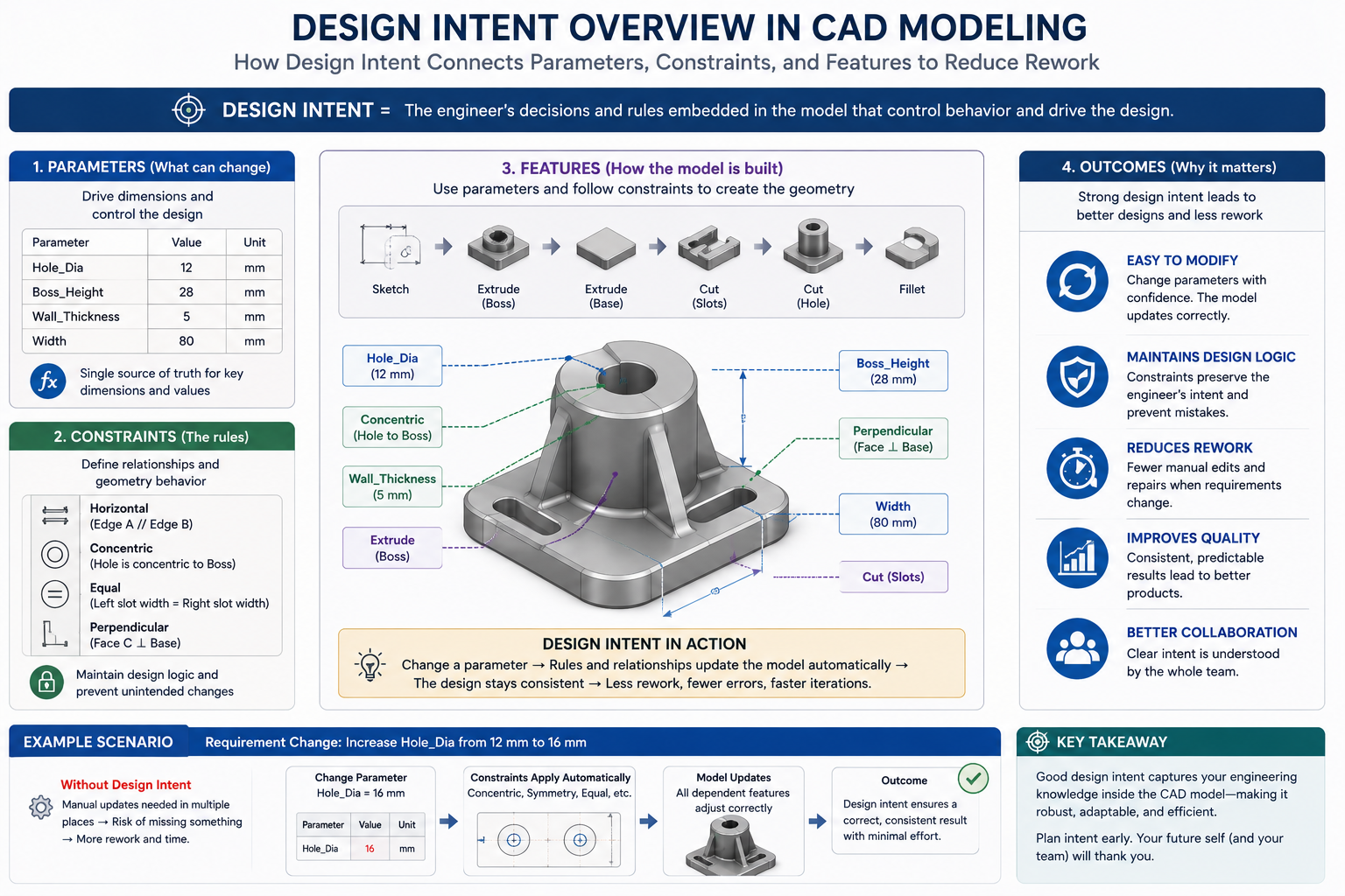
Design intent refers to the purpose, logic, and reasoning behind how a CAD model is constructed. It is not just about what the model looks like. It is about why the features exist in the order they do, how dimensions relate to each other, and how the model should behave when changes are made.
A classic definition used in the industry comes from PTC: design intent is a method in computer-aided design that defines relationships between objects so that a change to one propagates automatically to others. But in practice, it goes far beyond automated updates.
Think of design intent as the intelligence you build into a model. When a colleague opens your file six months from now and adjusts the flange width, does the bolt circle update automatically? Does the clearance hole stay in the right position? Does the drawing update correctly? If yes, your model has strong design intent. If not, expect rework.
Design intent encompasses:
- How you constrain sketches (fully defined, driven by reference geometry, or floating)
- The order of features in your feature tree (parent-child relationships)
- How dimensions are driven (hardcoded numbers vs. named parameters and equations)
- How parts relate to each other in assemblies (mates, references, skeleton models)
- How well the modeling logic is documented so others can understand and modify it
In short, design intent is the difference between a model that works once and a model that keeps working as your design evolves.
Read related article on Top CAD Modeling Mistakes That Delay Manufacturing
2. Why CAD Rework Happens (And What It Actually Costs)
Before we talk about how to fix the problem, it helps to understand exactly where it comes from. CAD rework is rarely caused by one single mistake. It usually results from a series of small modeling decisions that seemed fine at the time but compound into major problems later.
The Most Common Root Causes of CAD Rework
- Dimensions hardcoded as static numbers with no relationship to other features
- Sketches that are under-constrained or over-constrained
- Feature trees built in illogical order, creating unpredictable parent-child dependencies
- Parts modeled in isolation without considering how they fit into an assembly
- No naming conventions for features, dimensions, or parameters
- Geometry copied from other models without transferring the underlying logic
- Late-stage design changes that cascade through hundreds of downstream features
- Multiple engineers working on a model with no shared understanding of how it was built
The Real Cost of Poor Design Intent
Industry studies consistently show that rework accounts for a significant portion of total engineering time. A common estimate in product development literature is that 20 to 40 percent of engineering hours are spent correcting or redoing prior work. In CAD modeling specifically, rework tied to poor model structure can be even higher because one upstream error can invalidate an entire feature tree.
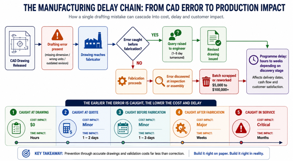
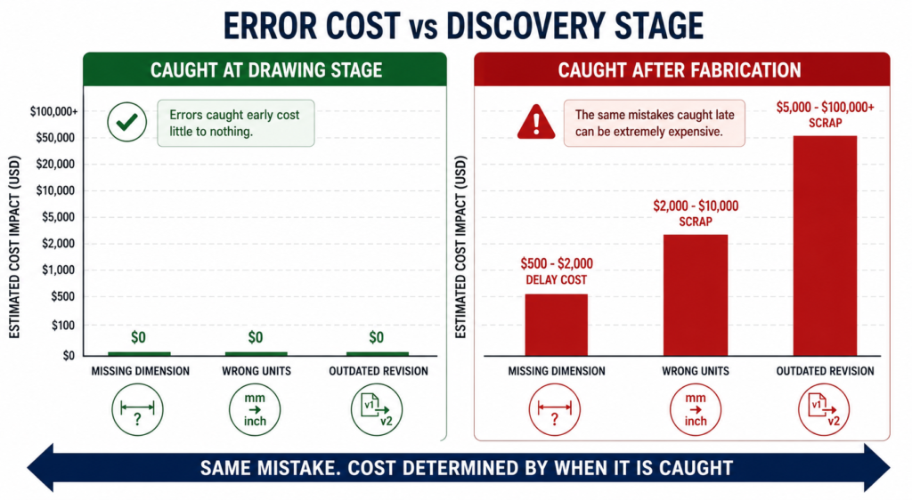
Beyond time, there are downstream costs to consider. Designs sent to manufacturing with unresolved errors lead to scrap material, tool changes, and production delays. In regulated industries such as aerospace or medical devices, design errors that slip through to production can have safety implications and regulatory consequences.
The good news is that the majority of these costs are preventable, and design intent is the primary preventive tool available to every engineer who works in CAD.
3. The Connection Between Design Intent and Rework Reduction
Here is the core insight: rework happens when a model does not behave the way the engineer expected when something changes. Design intent is the practice of building those expected behaviors directly into the model from the start.
When design intent is embedded correctly, a model with strong constraints and parametric relationships can absorb design changes gracefully. Change the wall thickness of a bracket and the ribs update. Change the diameter of a shaft and the bearing fits update. Change the number of bolts in a pattern and the bolt circle redistributes automatically. None of that requires manual rework because the model already knows what you intended.
When design intent is absent or poorly applied, each change becomes a manual task. Engineers hunt through the feature tree, fix broken references, override dimensions by hand, and check every dependent feature one by one. This is the definition of preventable rework.
The relationship is direct: stronger design intent equals less rework. And it is not just about saving time. Models with clear design intent are safer to modify, easier to hand off to other engineers, and faster to update when customer requirements change.
Read more on: Common CAD Drafting Mistakes That Cause Manufacturing Delays (and How to Avoid Them)
4. Core Principles of Design Intent in CAD Modeling
There are several foundational principles that every engineer should internalize before building any model. These are not software-specific tips. They apply whether you work in SolidWorks, CATIA V5, Creo, Inventor, or any other parametric CAD platform.
Principle 1: Model for Change, Not for Now
The most important mindset shift in design intent work is this: you are not modeling the design as it currently exists. You are modeling the design as it needs to behave when it changes. Before you create a single feature, ask yourself: what is likely to change about this part? What must stay fixed? What relationships need to be preserved regardless of how dimensions shift?
Principle 2: Fully Constrain Your Sketches
An under-constrained sketch is a liability. It might look fine today, but when dimensions are updated, the geometry can drift in unexpected directions. Fully defining your sketches using dimensions, geometric relations (coincident, parallel, perpendicular, tangent), and references to fixed geometry ensures that your sketch always produces predictable results.
Principle 3: Use Parameters, Not Numbers
Wherever possible, replace hardcoded dimensions with named parameters and equations. Instead of entering “24” as a hole depth, create a parameter called “WallThickness” and drive the hole depth with an equation. Now when the wall thickness changes, the hole depth updates automatically. This is one of the highest-leverage changes you can make to your modeling workflow.
Principle 4: Respect Parent-Child Relationships
Every feature that references another feature creates a parent-child dependency. If the parent changes or is deleted, the child feature may fail. Plan your feature tree so that parent features represent the most stable aspects of your design, and child features handle the details that are more likely to change.
Principle 5: Make Your Modeling Logic Readable
A model that only you can understand is a liability to your team. Use descriptive feature names, logical grouping, and in-model annotations so that any competent engineer can open your file and understand what you built and why. This is especially critical in companies where models are maintained over long product lifecycles.
5. How to Plan Design Intent Before You Start Modeling
One of the biggest mistakes engineers make is jumping straight into modeling without a plan. Five minutes of planning before you open the CAD tool can save hours of rework later. Here is a practical planning process you can adopt today.
Step 1: Define What Drives the Design
Ask yourself: what are the critical dimensions or requirements that everything else must reference? For a mounting bracket, it might be the bolt pattern and the interface surface. For a housing, it might be the internal cavity dimensions. Identify these “anchor” elements first, because they will form the backbone of your feature tree.
Step 2: Identify What Is Likely to Change
Talk to your team, review the design brief, and think about where flexibility will be needed. If the customer might want three different sizes of the product, build that variability into your parameters from day one. If the mounting interface is likely to shift, reference it from a flexible reference plane rather than hardcoding its position.
Step 3: Sketch Your Feature Tree on Paper
Literally draw out the order of features before you model them. Decide which features will be parents, which will be children, and where you will place major reference geometry. This takes ten minutes and can prevent hours of tree reconstruction later.
Step 4: Set Up Named Parameters Before Your First Sketch
Create your key parameters (height, width, wall thickness, bolt diameter, pitch, etc.) before you draw a single line. Reference these parameters in your sketches and features from the start. This is far easier than retrofitting parameters into a model that was built with hardcoded values.
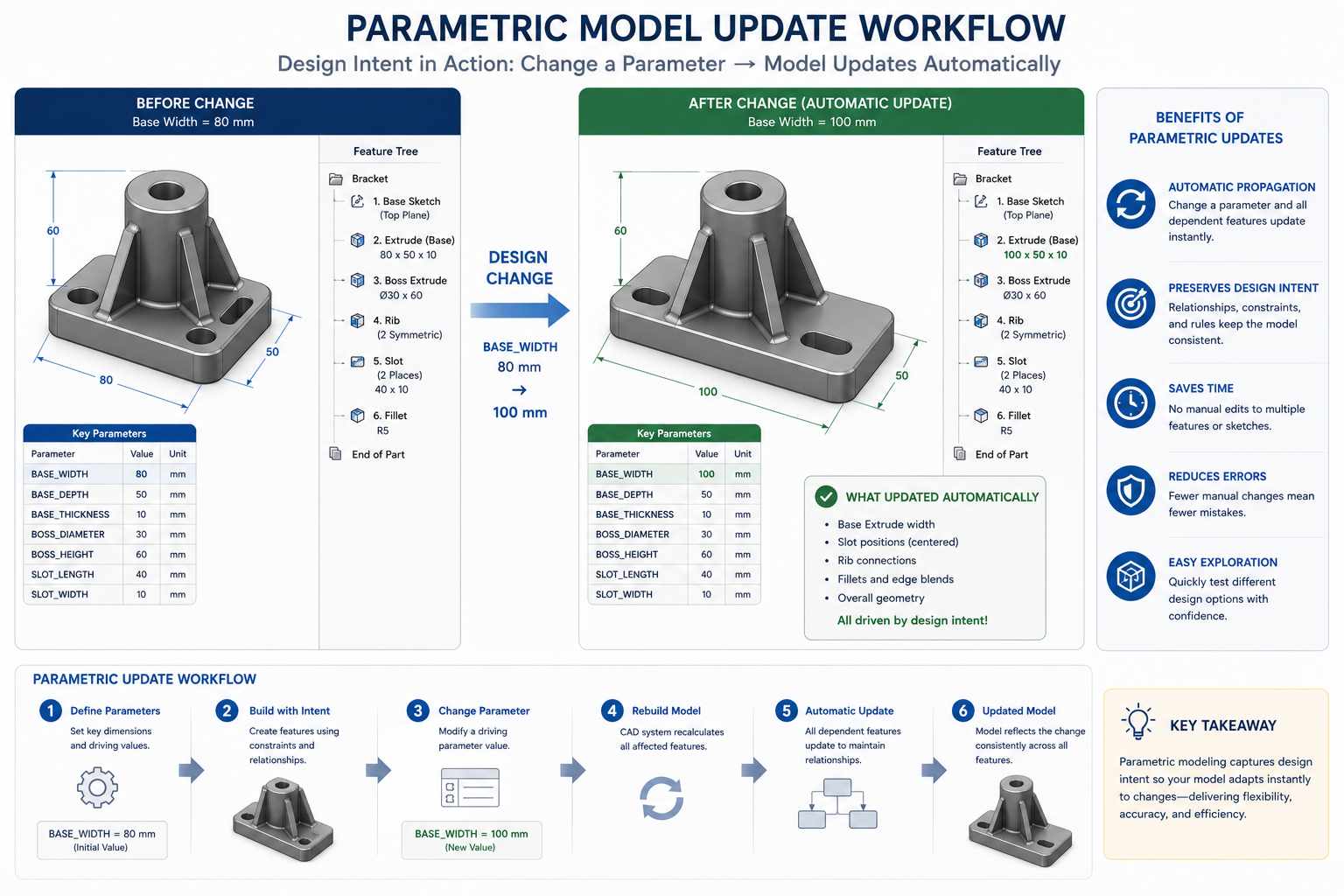
6. Parametric Modeling and Constraints: The Foundation of Design Intent
Parametric modeling is not just a CAD feature. It is the primary mechanism through which design intent gets encoded into a model. Understanding how to use it effectively is central to reducing rework.
What Makes a Model Truly Parametric?
A truly parametric model has all geometry driven by constraints and parameters, not by fixed coordinates or absolute positions. When you drag or modify a driving dimension, the model recalculates every dependent feature automatically. This is the behavior that makes rework reduction possible.
Geometric Constraints vs. Dimensional Constraints
These two types of constraints work together to define your geometry completely:
- Geometric constraints define relationships between sketch entities: lines that are parallel, arcs that are tangent, points that are coincident. These are relationship-based and do not have numeric values.
- Dimensional constraints define the size and position of geometry: the length of a line, the radius of an arc, the distance between two points. These take numeric values, ideally driven by named parameters.
Using both together gives you a sketch that is fully defined, predictable, and easy to update.
Equations: The Next Level of Design Intent
Most professional CAD tools allow you to write equations that link one parameter to another. For example: RibHeight = WallThickness * 1.5. Now every time the wall thickness changes, the rib height updates proportionally. This kind of relationship-driven modeling is what separates junior CAD users from senior design engineers.
You can also use equations to enforce design rules, such as minimum wall thickness for manufacturing, or to calculate derived values like volume, mass, or center of gravity. These smart equations embed real engineering knowledge directly into the model.
The Danger of Over-Constraining
It is possible to add too many constraints. An over-constrained sketch will refuse to update correctly because the constraints conflict with each other. Always aim for fully constrained but not over-constrained. Most modern CAD tools will warn you when a sketch is over-constrained, so pay attention to those warnings.
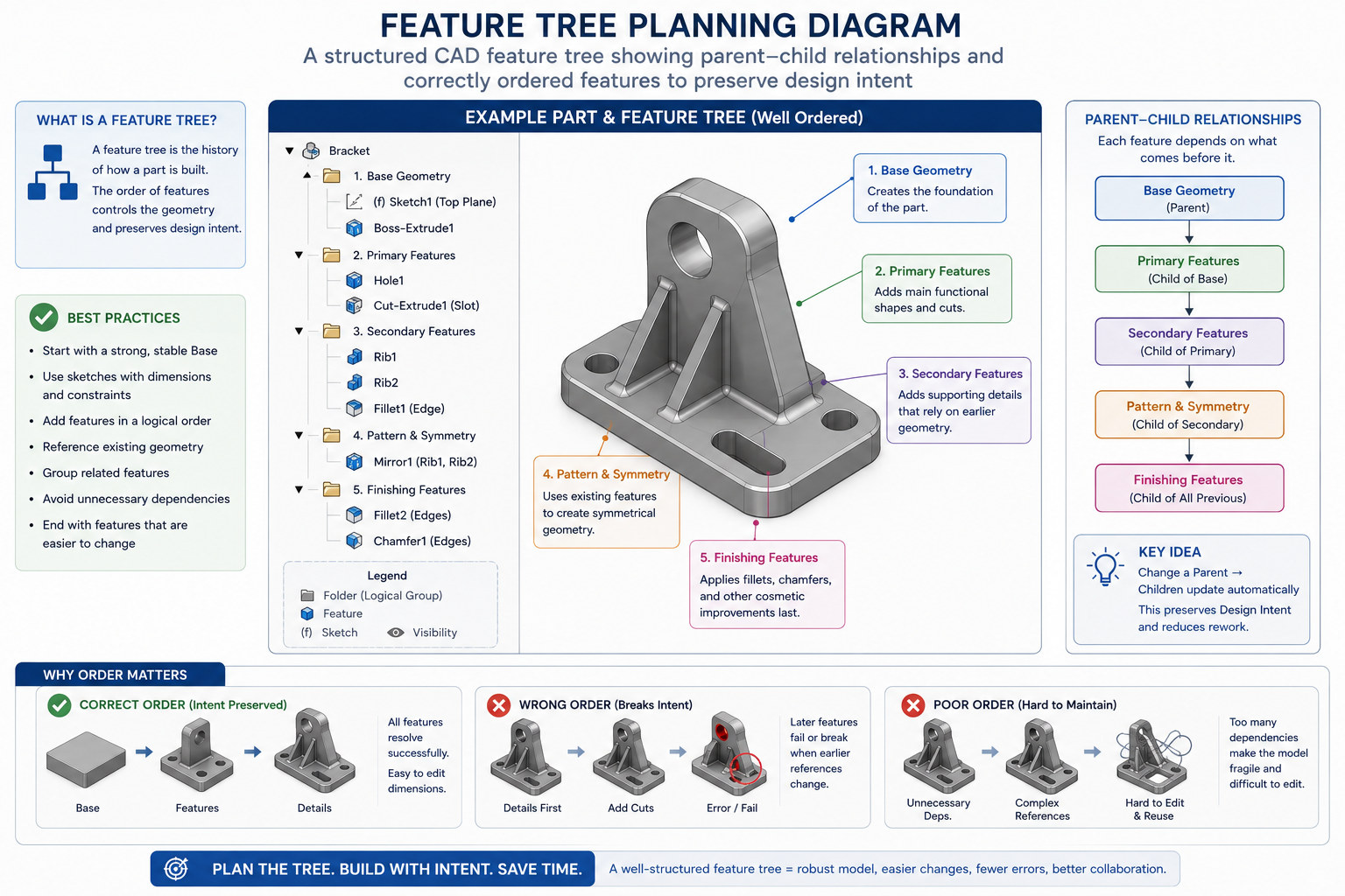
7. Feature Tree Planning: Order Matters More Than You Think
The order of features in your CAD feature tree is not just organizational housekeeping. It directly determines how robust your model will be when changes are made. Getting this order right is one of the most practical skills you can develop for reducing rework.
The Parent-Child Cascade Problem
Every feature in a parametric CAD model exists in a dependency chain. A hole references a face. That face is generated by an extrusion. That extrusion references a sketch. That sketch is constrained to a reference plane. Change anything in that chain and everything downstream is affected.
The problem comes when high-level decisions are buried deep in the tree, or when stable features depend on unstable ones. Plan your tree so that the most fundamental, least-likely-to-change features sit at the top, and the details that are more likely to evolve sit further down.
Best Practices for Feature Tree Organization
- Start with reference geometry: origin planes, datum planes, axes, and coordinate systems
- Follow with the primary body-defining features (base extrusions, revolves, lofts)
- Add major form features next (flanges, bosses, ribs)
- Apply detail features later (fillets, chamfers, cosmetic features)
- Add holes, cutouts, and patterns after the primary geometry is established
- Use folders or groups to organize related features and keep the tree readable
- Name every feature descriptively, not as the default “Extrude1” or “Cut2”
Fillets: Why They Should Almost Always Come Last
This is a tip that trips up many newer engineers. Fillets add curvature to edges. When placed early in the feature tree, they create curved surfaces that other features reference. If you later modify the geometry before the fillet, the fillet may fail or produce unexpected results. As a general rule, apply fillets and chamfers at the end of your feature sequence, after all structural geometry is complete.
8. Using Skeleton Models and Master Sketches
For complex parts or large assemblies, skeleton modeling is one of the most powerful design intent tools available. It may take a bit more setup upfront, but it pays dividends in dramatically reduced rework throughout the product lifecycle.
What Is a Skeleton Model?
A skeleton model is a simplified, lightweight master reference file that contains the key geometry that drives your entire assembly: critical interfaces, bolt patterns, envelope boundaries, datum planes, and axes. All individual part models reference this skeleton, so when the skeleton changes, every dependent part updates automatically.
This approach is particularly common in aerospace, automotive, and industrial machinery design, where assemblies contain hundreds or thousands of parts that must maintain precise spatial relationships.
Master Sketches in Single Parts
You do not need a complex assembly to benefit from skeleton modeling logic. In a single complex part, you can create a master sketch (sometimes called a layout sketch) at the very top of your feature tree that defines the overall envelope and key reference dimensions. All subsequent features reference this master sketch, so geometry changes propagate through the entire part automatically.
The Business Case for Skeleton Modeling
An aerospace engineering team that adopts skeleton-driven assembly modeling can reduce late-stage design change time by a significant margin. Instead of a cascading series of manual updates across dozens of part files, the engineer modifies the skeleton once and reviews the downstream updates. The investment in setting up the skeleton pays back on the very first major engineering change.
9. Naming Conventions and Documentation Inside Your Model
This section is often skipped in CAD training, and it shows. Walk through any large engineering company and you will find CAD files with features named “Boss-Extrude47” and parameters called “d1@Sketch3”. This kind of naming makes models nearly impossible to understand, maintain, or modify without the original author present.
Why Naming Conventions Reduce Rework
When features and parameters are named clearly, every engineer who opens the file can immediately understand what each element represents. Changes become safer because the intent is visible. Troubleshooting a failed rebuild is faster because you can identify which feature broke and why. And onboarding new team members to existing models becomes a fraction of the time it would otherwise take.
Practical Naming Guidelines
- Features: Use format [Type_Description_Reference]. Examples: Extrude_BasePlate, Cut_BoltHole_M8, Fillet_FlangeToCylinder
- Parameters/Dimensions: Use clear noun phrases. Examples: FlangeDiameter, WallThickness, BoltCirclePCD, ThreadDepth_M10
- Sketches: Name each sketch by what it drives. Examples: Sketch_BaseProfile, Sketch_MountingPattern, Sketch_RibLayout
- Reference Geometry: Name planes and axes by their location or purpose. Examples: Plane_TopOfFlange, Axis_BoltCircleCenter
In-Model Documentation
Most CAD tools allow you to add notes or comments directly within the model or feature tree. Use these to explain non-obvious decisions. Why is the rib at 45 degrees and not 60? Why is the wall thickness driven by an equation rather than a direct input? These decisions, documented in the model, transform it from a collection of geometry into a record of engineering reasoning.
10. Design Intent in Assemblies vs. Individual Parts
Design intent applies differently depending on whether you are working on a standalone part or a complex assembly. Understanding the distinction helps you apply the right strategies in the right context.
Part-Level Design Intent
At the part level, design intent is primarily about how the geometry responds to dimensional changes. The tools are parametric sketches, feature ordering, named parameters, equations, and in-part reference geometry. The goal is a model that correctly captures one component’s functional behavior and physical geometry.
Assembly-Level Design Intent
At the assembly level, design intent extends to how parts relate to each other. Mates in SolidWorks, constraints in Inventor, or assembly constraints in CATIA define positional and orientation relationships between components. These should be driven by the same philosophy: mate to meaningful geometry (functional surfaces, centerlines, symmetry planes) rather than arbitrary edges or vertices.
Assembly design intent also involves deciding the hierarchy of component relationships. Which part is the anchor? Which parts move relative to which others? How are kinematic constraints expressed? Getting this right prevents assembly rebuild failures and reduces the manual effort required when component geometry changes.
Top-Down vs. Bottom-Up Assembly Modeling
Bottom-up modeling means building each part independently and assembling them afterward. It is faster for individual components but can miss interface requirements.
Top-down modeling means using the assembly context to drive individual part geometry. Parts are modeled in place, referencing each other through the skeleton or through in-context references. It is more complex to set up but preserves design intent far more effectively in large assemblies.
Most experienced engineers use a hybrid approach: define key interfaces top-down, then detail individual parts bottom-up.
11. Common Design Intent Mistakes That Cause Rework
Even experienced engineers make these mistakes. Knowing them helps you avoid them, and recognizing them in existing models helps you fix them before they compound.
Mistake 1: Referencing Unstable Geometry
Referencing a specific edge, face, or vertex that is likely to change is one of the most common causes of feature failures. When that edge is modified or deleted, every downstream feature that references it breaks. Use reference planes, axes, and named parameters instead of direct edge references wherever possible.
Mistake 2: Building Long, Linear Feature Trees
A feature tree where every feature depends on the one directly above it is fragile. Change anything near the top and everything below must rebuild. Use parallel feature structures and reference geometry to reduce these long dependency chains.
Mistake 3: Hardcoding Repeated Values
If the same dimension appears in multiple places (bolt diameter, clearance gap, material thickness), it should be a named parameter that appears once and is referenced everywhere. Hardcoding the same value in twelve different sketches means that a change to that dimension requires twelve manual edits, with a high risk of missing one.
Mistake 4: Suppressing Instead of Deleting
Suppressing a failed or unwanted feature feels like a quick fix. But suppressed features remain in the tree, continue to affect rebuild time, and can cause confusing behavior if accidentally re-enabled. Fix or delete features rather than suppressing them as a workaround.
Mistake 5: Ignoring the Feature Tree Until It Is a Mess
The feature tree is a living document of your modeling decisions. Clean it up as you go. Rename features when you create them. Reorganize when you add a major design section. Leaving cleanup to later usually means it never happens, and the next engineer to open the file spends hours deciphering what the model does before they can change anything.
12. Comparison: Modeling Approaches and Their Rework Risk
Not all CAD modeling approaches carry equal rework risk. The table below summarizes how different approaches perform across key design intent criteria.
| Modeling Approach | Design Intent Preserved? | Rework Risk | Flexibility |
| Parametric modeling with constraints | Yes | Low | High |
| Direct modeling (no constraints) | No | High | Low |
| Parametric with poor feature order | Partial | Medium | Medium |
| Skeleton-driven assembly modeling | Yes | Very Low | Very High |
| Copy-paste geometry (dumb solids) | No | Very High | Very Low |
As the table makes clear, parametric modeling with well-planned constraints and skeleton references consistently delivers the lowest rework risk. The upfront investment in structure pays back many times over across the life of a design.
13. Real-World Examples of Design Intent in Action
Example 1: Automotive Bracket Family
A tier-one automotive supplier needed to produce five variants of a suspension bracket for different vehicle platforms, each with a slightly different bolt pattern, wall thickness, and overall envelope. Rather than building five separate models, their lead engineer created one parametric model with a configuration table. Each variant was a configuration driven by named parameters. When a material change required a 10% increase in wall thickness across all variants, the engineer changed one parameter and all five configurations updated in under a minute. Manual approach would have required hours of rework across five files.
Example 2: Industrial Machine Redesign
A manufacturing equipment company received a request to scale up an existing machine frame by 25% while maintaining all interface dimensions at the control panel. The original model had been built without design intent: dimensions were hardcoded, features were randomly ordered, and nothing was named. The redesign took two weeks of rework. The company subsequently invested in rebuilding their standard frame models with full parametric intent. The next scale-up request, which came eight months later, was completed in a single afternoon.
Example 3: Aerospace Assembly Change Management
An aerospace design team used skeleton-driven assembly modeling for a complex wing rib assembly. When a structural analysis revealed that the main spar needed to shift forward by 12 millimeters to optimize load distribution, the engineer updated the spar reference plane in the skeleton model. All 47 dependent rib components updated their positional relationships automatically. The design review the following day confirmed that all interfaces remained correct. Without the skeleton, each rib would have required individual manual repositioning.
14. Frequently Asked Questions
Q: What is design intent in CAD?
A: Design intent is the reasoning and logic behind how a CAD model is built. It defines the relationships between features, dimensions, and constraints so that the model behaves predictably when changes are made.
Q: How does design intent reduce CAD rework?
A: When a model is built with clear design intent, changes propagate automatically through related features. You do not have to manually fix every dimension or relationship each time the design evolves.
Q: What are the most common causes of CAD rework?
A: Common causes include poorly ordered feature trees, over-constrained or under-constrained sketches, hardcoded dimensions instead of parameters, lack of naming conventions, and missing documentation of modeling decisions.
Q: What is parametric modeling and how does it support design intent?
A: Parametric modeling uses dimensions and constraints to define geometry. Changing one parameter automatically updates all dependent features. This is the foundation of intent-driven CAD modeling.
Q: How do you document design intent in a CAD model?
A: Use descriptive feature and parameter names, add in-model notes and annotations, maintain a design rationale document, and structure your feature tree logically so that others can follow your modeling decisions.
Q: What is a skeleton model in CAD?
A: A skeleton model is a master reference geometry (planes, axes, key points) that drives the entire assembly. When one part changes, all others update through the skeleton, which drastically reduces rework in large assemblies.
Conclusion
Every hour you spend building design intent into your CAD models is an hour that prevents multiple hours of rework later. This is not a theoretical claim. It is the lived experience of every senior CAD engineer who has managed complex product designs through multiple revision cycles.
The practices covered in this guide, from fully constraining sketches and using named parameters with equations, to planning your feature tree order and adopting skeleton-driven assembly modeling, form a coherent system. They are not isolated tips. They are parts of an approach to modeling that treats the CAD file as a living engineering document rather than a static picture of geometry.
Start small if the full approach feels overwhelming. Pick one model you are currently building and apply just two or three of these principles: name your features properly, set up parameters before your first sketch, and plan your feature order on paper. Notice the difference when you make your first revision.
Then go further. Review your team’s modeling standards. Audit your most-modified models for design intent weaknesses. Invest in rebuilding your most frequently reused part templates with better parametric structure. Each of these steps compounds over time into a measurable reduction in engineering rework across your organization.
Design intent is not a feature in your CAD software. It is a skill. And like any engineering skill, it improves with deliberate practice.
Ready to reduce CAD rework in your team?
Explore related guides on parametric modeling best practices, CAD file management, and design for assembly to build a complete, rework-resistant CAD workflow.