In 2019, the aerodynamics team at a major automotive OEM compared the drag coefficient predictions from their CFD model against their full-scale wind tunnel measurement for the same production vehicle. The CFD result was 0.273. The tunnel result was 0.281. The eight drag-count difference, 0.008 Cd, represented approximately 0.8 percent additional fuel consumption at highway speed, translating to roughly 0.15 liters per 100 km across the fleet. Across 200,000 vehicles produced annually, over a 10-year vehicle life, that eight drag-count discrepancy was worth approximately $180 million in fuel cost to their customers.
The question was not whether CFD or the tunnel was ‘better’, both were used. The question was which result to trust for homologation and which to use for design exploration.
That question, which method to trust for which decision, is what the CFD vs wind tunnel debate is actually about. Not a competition between two methods, but a decision framework for deploying each where it delivers the most value. CFD and wind tunnel testing are not substitutes for each other in any demanding aerodynamic application. They are complementary tools with different strengths, different limitations, different costs, and different appropriate use cases. Understanding the technical basis of those differences, not just the intuitive ones, but the specific error sources, accuracy ranges, and conditions where each method fails, is the prerequisite for making correct deployment decisions.
This article provides that technical basis: the complete 12-parameter comparison table, the turbulence model hierarchy and its accuracy boundaries, the seven wind tunnel correction factors and their magnitudes, the Reynolds number problem that each method handles differently, and the 12-case decision table that maps specific applications to the recommended primary and secondary methods with justification. The article also addresses the increasingly important question of CFD validation against tunnel data, how to build a CFD model that can be trusted for extrapolation beyond the test conditions, and what level of agreement between CFD and tunnel constitutes adequate validation.
What Each Method Actually Measures
Before comparing the two methods, it is essential to understand what each one fundamentally does, because they are not measuring or predicting the same thing in the same way, and this asymmetry drives most of the nuance in the comparison.
A wind tunnel test measures the integrated aerodynamic forces and moments on a physical model in a controlled flow environment. The fluid is real. The turbulence is real. The boundary layer transition from laminar to turbulent flow happens as it would in nature, at the Reynolds number of the test (which may or may not match the full-scale Reynolds number, more on this below).
The measurement instruments, force balances, pressure taps, particle image velocimetry (PIV) systems, hot-wire anemometers, have measurement uncertainty, calibration drift, and installation effects that must be quantified and corrected. The tunnel itself has walls, a model support structure, and a boundary layer growing on its walls, all of which affect the flow around the model in ways that must be corrected before the data represents free-air conditions.
A CFD simulation solves the Navier-Stokes equations numerically for a mathematical model of the fluid domain. The governing equations are exact, they correctly describe fluid motion at any Reynolds number, including turbulent flow. The problem is that solving them exactly (Direct Numerical Simulation) requires resolving every turbulent eddy down to the Kolmogorov scale, which at engineering Reynolds numbers would require computational meshes of 10¹² to 10¹⁶ elements and thousands of years of compute time on current hardware.
Every practical CFD method approximates the turbulence: RANS models time-average the equations and model all turbulence effects; LES models resolve large eddies and model only small eddies; DES uses RANS near walls and LES in separated regions. The approximation introduces modeling uncertainty that is the fundamental limitation of CFD accuracy.
The Fundamental Asymmetry: Modeling vs Measurement Uncertainty
This leads to the fundamental asymmetry between the two methods. Wind tunnel tests have measurement uncertainty, errors in the instruments, the corrections, and the test conditions, but they measure real fluid behavior. CFD has modeling uncertainty, errors in the turbulence model approximations, the boundary condition assumptions, and the numerical discretization, but given a correct model, it predicts the full flow field at every point in the domain.
The practical consequence: wind tunnel results are more trustworthy for configurations where CFD modeling uncertainty is large (massively separated flow, high angle of attack, complex turbulent wake structures) but less useful for configurations where measurement corrections are large and uncertain (very high Reynolds number, novel geometry with no correction calibration data, aeroelastic deformation). CFD is more trustworthy for configurations where the physics is well-captured by RANS (attached flow at cruise conditions, internal pipe flow, HVAC) and where parametric variation is needed that would be too expensive to test physically.
CFD vs Wind Tunnel: The 12-Parameter Comparison
The following table provides a structured comparison across twelve parameters that determine which method is appropriate for a given application. The ‘Verdict’ column identifies which method has the advantage for each parameter, but note that no single method wins on all parameters, which is why both continue to be used in demanding aerodynamic programs.
| Parameter | CFD | Wind Tunnel Testing | Verdict |
| Cost per test/run | $500–$5,000 per simulation run (compute + analyst time); large RANS runs $2,000–$10,000; LES/DES $10,000–$100,000+ | $20,000–$500,000 per wind tunnel entry; model fabrication $50,000–$500,000 additional for complex scale models | CFD wins for parametric studies; tunnel wins for single definitive result on complex geometry |
| Setup time | CAD to first result: 1–5 days for RANS; 1–4 weeks for high-fidelity LES/DES | Model fabrication: 4–16 weeks; tunnel booking lead time: 4–26 weeks at major facilities | CFD wins decisively, weeks vs months |
| Design iteration speed | Geometry change to new result: hours to days; automated parametric sweeps possible | Each geometry change requires model modification or new model build: weeks per iteration | CFD wins, orders of magnitude faster iteration |
| Physical realism | Depends entirely on turbulence model choice; RANS misses separated flow; LES captures more physics at high cost | Real fluid at real Reynolds number (if correctly scaled); no turbulence modelling assumptions | Wind tunnel wins for complex separated flows and high-Re regimes where turbulence models are uncertain |
| Reynolds number matching | Full-scale Re achievable at any geometry size; no scaling required | Requires pressurized tunnel, cryogenic tunnel, or geometric scaling to match Re, expensive or limited | CFD wins, exact Re matching is trivial |
| Measurement completeness | Full-field data: pressure, velocity, temperature, turbulence quantities at every point in the domain | Point measurements (pressure taps, hot wires); limited field measurements (PIV); no internal flow data without probes | CFD wins for full-field insight; tunnel wins for boundary layer detail |
| Accuracy for attached flow (low angle of attack) | RANS within 1–5% of measured drag and lift for well-attached flow; excellent for cruise conditions | Directly measures forces and moments; gold standard for attached flow aerodynamics | Tunnel wins or ties, RANS is accurate here but tunnel has no modeling uncertainty |
| Accuracy for separated/turbulent flow | RANS significantly over-predicts separation; LES/DES accurate but expensive; fundamental modeling uncertainty remains | Measures actual separated flow if Re is correctly matched; no turbulence model uncertainty | Tunnel wins, RANS is unreliable for separated flow; only LES/DES approaches tunnel quality |
| Multi-physics coupling | Fluid-structure interaction, aero-acoustic, conjugate heat transfer available in same framework | Structural response requires separate instrumentation; acoustics measured separately; heat transfer limited | CFD wins, integrated multi-physics analysis |
| Regulatory acceptance | Accepted in many industries as primary method or supplement; required by some codes (wind engineering, CFD for novel aircraft); not universally accepted for certification | Gold standard for aerospace certification (FAA AC 25.1); required for final drag polar in commercial aviation | Tunnel required for aviation certification; CFD accepted in most other industries |
| Intellectual property risk | Geometry stays in-house; no external exposure | Scale model sent to test facility; contractor has access to proprietary geometry | CFD wins for IP-sensitive programs |
| Uncertainty quantification | Grid study, model sensitivity, boundary condition sensitivity quantifiable systematically | Tunnel correction factors (blockage, wall interference, model support) introduce uncertainty that is difficult to fully quantify | CFD provides more systematic uncertainty pathway; tunnel corrections are empirical |
The Turbulence Modeling Problem: Why CFD Accuracy Is Flow-Dependent
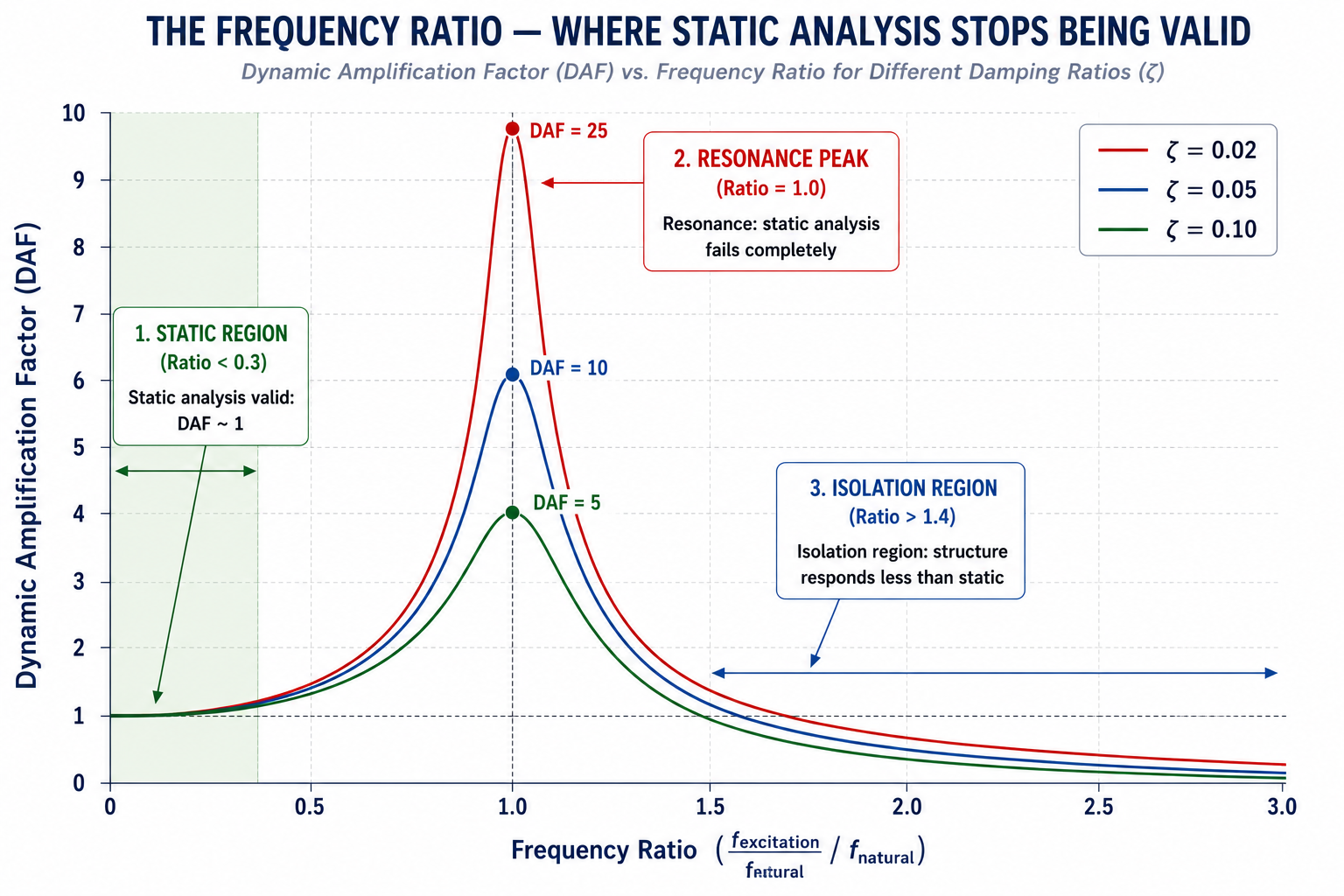
The accuracy of CFD for aerodynamic prediction is not a fixed number, it is a strong function of the flow regime, specifically of how much turbulent separation is present. For fully attached flow at cruise conditions, the flow regime that governs fuel efficiency in commercial aviation and highway aerodynamics for cars, RANS CFD is highly accurate, typically predicting lift and drag within 3 to 5 percent of tunnel measurement. For massively separated flow, bluff bodies, high angle of attack, post-stall aerodynamics, RANS CFD fails systematically and significantly, over-predicting attached regions and under-predicting wake size. Understanding which turbulence model to use, and when RANS is fundamentally inadequate, is the central technical competency for CFD aerodynamics work.
| Model | Full Name | Computational Cost | Accuracy for Attached Flow | Accuracy for Separated Flow | Typical Use Case |
| RANS k-ε | Reynolds-Averaged Navier-Stokes, k-epsilon closure | Low (1x baseline) | Good, within 3–5% for drag and lift at low AoA | Poor, over-predicts separation, under-predicts wake width | External aerodynamics at cruise; HVAC; pipe flow; early design exploration |
| RANS k-ω SST | k-omega Shear Stress Transport | Low (1.1x) | Very good, better near-wall behaviour than k-ε; standard for aerodynamics | Moderate, better than k-ε for mild separation; still unreliable for massively separated flow | Automotive aerodynamics; aircraft cruise; most industrial external flow |
| RANS Spalart-Allmaras | One-equation RANS | Very low (0.8x) | Good for attached boundary layers; standard in aerospace RANS | Poor for separated flow, single equation cannot capture complex turbulence | Aerospace RANS (primary model in NASA CFD); thin airfoil attached flow |
| DES | Detached Eddy Simulation | High (10–50x RANS) | Good, RANS near walls, LES in separated regions | Good, captures unsteady separated flow that RANS misses; time-averaged results competitive with tunnel | High-AoA aerodynamics; bluff body flows; automotive separated wake |
| LES | Large Eddy Simulation | Very high (100–1000x RANS) | Excellent, resolves large turbulent structures directly | Excellent, captures unsteady separated flow, wake dynamics, acoustic sources | Aeroacoustics; fundamental turbulence research; complex separated flows where DES is insufficient |
| DNS | Direct Numerical Simulation | Prohibitive (10^6–10^9x RANS) | Exact, resolves all scales of turbulence | Exact, no turbulence modelling | Low-Re academic research only; not used in industrial aerodynamics |
Why RANS Fails for Separated Flow
Reynolds-Averaged Navier-Stokes (RANS) models work by time-averaging the Navier-Stokes equations and representing the effect of turbulent fluctuations through a turbulent viscosity, an additional viscous-like term that smears out the turbulent mixing. This works well for attached turbulent boundary layers, where the turbulence is reasonably well described by a local equilibrium between production and dissipation of turbulent kinetic energy. It fails for separated shear layers, where the turbulence is far from local equilibrium, where large unsteady vortex structures shed periodically, and where the flow field is inherently three-dimensional and time-dependent.
The specific failure mode of RANS in separated flow is reattachment prediction. RANS models systematically predict that separated flow will reattach to the surface earlier than it does in reality, producing a smaller separation bubble, a narrower wake, and lower drag than the physical flow. For a bluff body (a truck, a building, a high-angle-of-attack wing), RANS under-predicts drag by 10 to 30 percent because it predicts a narrower, more rapidly reattaching wake than actually exists. This is not a mesh density problem, refining the RANS mesh does not fix this error, because the error is in the turbulence model, not in the numerical discretization.
The solution is scale-resolving simulation: DES (which switches from RANS near walls to LES in separated regions) or full LES (which resolves large turbulent eddies directly and models only the small ones). These methods capture the unsteady large-scale vortex shedding that RANS time-averages away, producing time-accurate predictions of the separated flow that, when averaged over sufficient time, agree with tunnel measurements to within 5 to 10 percent for bluff body drag. The cost is 10 to 100 times higher compute time than RANS, but for applications where separated flow governs the answer, it is the only CFD path to reliable results.
The k-ω SST Model: Why It Became the Industrial Standard
The k-omega Shear Stress Transport (SST) model, developed by Florian Menter at NASA in 1993, has become the default turbulence model for industrial aerodynamics CFD. Its dominance is not accidental: SST combines the strengths of two earlier models, the k-ε model’s robustness in the freestream and the k-ω model’s superior near-wall behavior, through a blending function that transitions between them based on distance from the wall.
For attached and mildly separated flows, SST consistently outperforms both k-ε and Spalart-Allmaras across a wide range of geometries and flow conditions. It is not the most accurate model for any specific flow type, but it is the most consistently reliable across the range of conditions found in a typical aerodynamic design campaign. For automotive external aerodynamics, where the flow is moderately separated in the near-wake but attached elsewhere, SST is the standard choice at major OEMs and is accepted by regulatory bodies (homologation wind tunnel standards) as a valid CFD methodology when properly validated.
Wind Tunnel Limitations: The Corrections That Make Raw Data Unreliable
Wind tunnels are not perfect simulators of free-air flight or driving conditions. Every wind tunnel test requires a set of data corrections to convert the raw measurements into values that represent the aerodynamic performance of the full-scale vehicle or structure in free air. These corrections are based on analytical models, empirical data, and tunnel-specific calibration constants that introduce their own uncertainty. Understanding the magnitude and uncertainty of wind tunnel corrections is essential for correctly interpreting tunnel data and for understanding why ‘tunnel data’ is not the same as ‘truth data’.
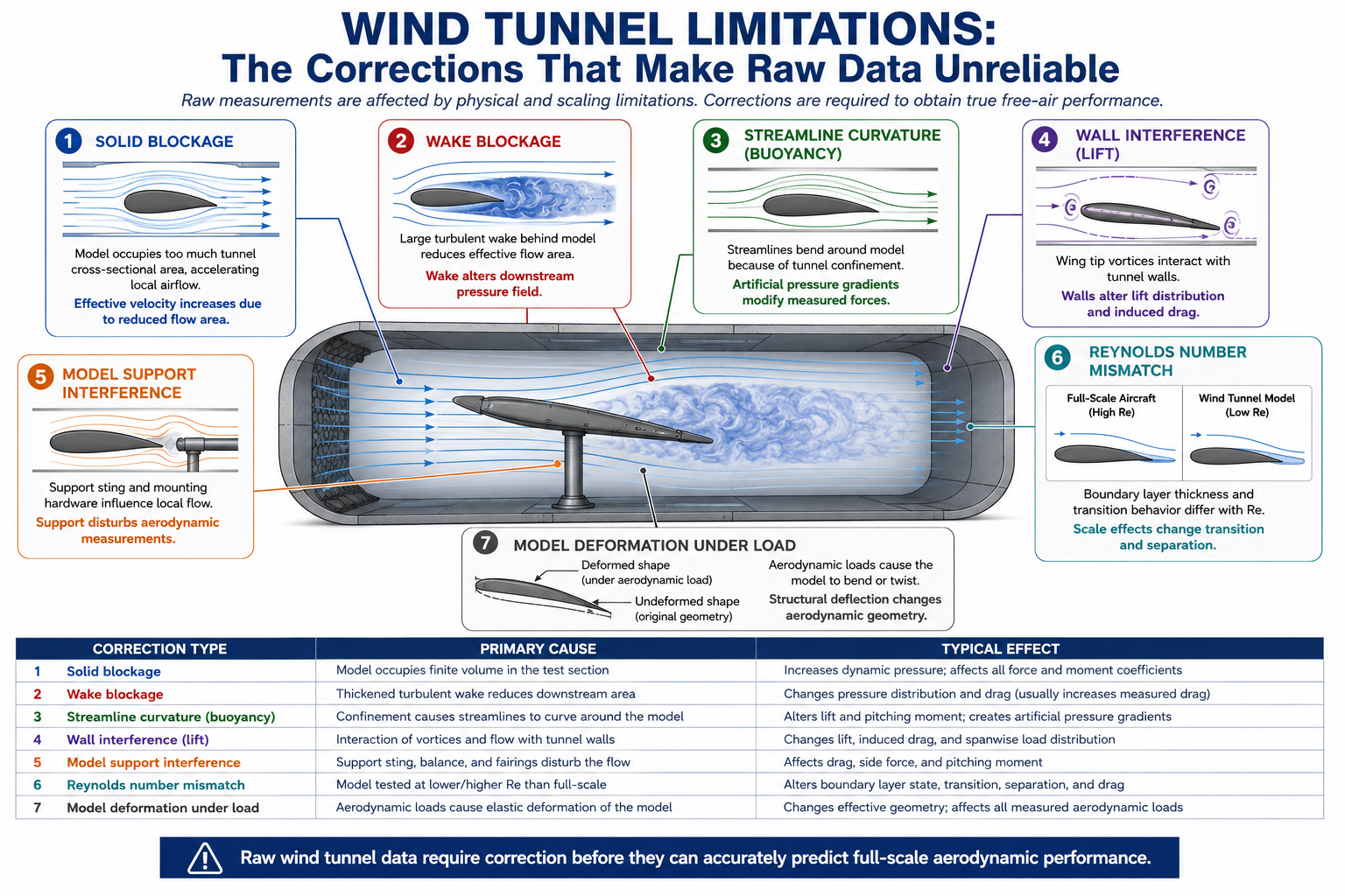
| Correction Type | Physical Cause | Typical Magnitude | Effect if Uncorrected | Standard Method |
| Solid blockage | Model frontal area displaces streamlines, increasing local velocity above freestream | 0.5–5% velocity increase for blockage ratio 0.5–5% | Drag and lift overestimated; results not representative of free-air conditions | Maskell or Thom method based on model frontal area / test section area ratio |
| Wake blockage | Model wake displaces streamlines, further accelerating flow around model | 0.5–3% additional to solid blockage | Additional drag overestimation; particularly significant for bluff bodies with large wakes | Combined with solid blockage in Maskell method; or experimental with empty tunnel reference |
| Streamline curvature (buoyancy) | Longitudinal pressure gradient in tunnel due to growing boundary layer causes apparent drag increase | 0.5–2% drag correction for large tunnels; larger in smaller facilities | Drag overestimated; effect proportional to model length relative to tunnel length | Horizontal buoyancy correction using measured axial pressure gradient |
| Wall interference (lift) | Tunnel walls constrain wing tip vortices, reducing induced downwash below free-air value; lift slope increased | 1–5% lift correction for typical aircraft models; larger for high-span models | Effective angle of attack and induced drag not representative of free air; lift curve slope too steep | Prandtl-Glauert correction or panel method wall interference calculation from wall pressure measurements |
| Model support interference | Sting, strut, or wire support system adds its own aerodynamic force to measured model force | 1–10% drag interference; difficult to quantify precisely | Drag and pitching moment contaminated by support aerodynamics | Dummy sting/strut test to quantify support interference; subtract from model result |
| Reynolds number mismatch | Model tested at lower Re than full-scale; boundary layer transition location differs; skin friction drag different | 1–15% drag error depending on Re ratio and surface roughness treatment | Drag polar, stall angle, and maximum lift significantly different from full-scale if transition not correctly matched | Boundary layer trip (roughness strip) to force transition at model location; Re correction factor |
| Model deformation under load | Aerodynamic loads bend wing models; deformed shape is what the tunnel sees, not the design shape | Wing twist up to 1–2 degrees for typical structural models under full load | Aeroelastic deformation changes effective incidence; lift distribution differs from rigid model assumption | Optical measurement of model deformation under load; correct aerodynamic data to zero-load shape |
The Reynolds Number Problem: Scale Models and Real Conditions
The most fundamental limitation of wind tunnel testing is the Reynolds number scaling problem. The Reynolds number Re = rho*V*L/mu governs the ratio of inertial to viscous forces in a flow. Two flows at the same Reynolds number are dynamically similar, they have the same non-dimensional flow structure regardless of the actual velocities and length scales. A scale model tested at the correct Reynolds number produces aerodynamic coefficients that correctly represent the full-scale vehicle.
The problem: for a 1/4-scale model to match the full-scale Reynolds number, the tunnel airspeed must be four times the full-scale speed. For a commercial aircraft cruising at 250 m/s (Mach 0.85), the 1/4-scale model would need to be tested at 1,000 m/s, well above the speed of sound, completely changing the compressibility effects.
Solutions exist but are expensive: pressurized tunnels increase air density to raise Re at the same velocity (NASA’s National Transonic Facility and ETW in Cologne operate at up to 9 atmospheres); cryogenic tunnels reduce air viscosity by cooling to -170°C, raising Re for the same speed (ETW operates at both pressure and cryogenic conditions simultaneously, achieving full-scale Re for large aircraft models). Both approaches add significant cost and operational complexity to testing.
CFD has no Reynolds number scaling problem. A CFD simulation runs at exactly the full-scale Reynolds number regardless of the geometry scale, the mesh simply needs to resolve the boundary layer at the actual flow conditions. This is one of CFD’s clearest advantages over wind tunnel testing: the simulation represents the actual vehicle at the actual operating condition, with no scaling uncertainty to correct for.
The Model Support Interference Problem
Every wind tunnel model must be supported in the tunnel by some structure, a sting attached to the model base and supported by a central strut, side struts, wires, or a floor-mounted support. Each support structure creates its own aerodynamic disturbance that contaminates the measurement: the sting interferes with the base pressure, the struts interfere with the wing tip flow or the fuselage boundary layer, and the wake of the support structure interacts with the model wake.
The standard approach to quantifying support interference is the dummy support test: a mirror-image of the support structure is installed in the tunnel without a model attached, and its aerodynamic force is measured. This force is then subtracted from the model-plus-support measurement to give the isolated model result. This approach works reasonably well for simple support geometries but cannot account for the mutual aerodynamic interference between the support and the model, the way the presence of the support changes the flow around the model and vice versa. This mutual interference is particularly significant for rear-steer and sting-supported aircraft models where the sting enters the model base in the middle of the wake region that governs base drag.
CFD Validation Against Wind Tunnel Data: Building Trustworthy Simulations
CFD validation, comparing simulation predictions against trusted experimental measurements, is the process by which a CFD model earns the right to be used for design decisions beyond the tested configuration. A CFD model that has not been validated is not yet a reliable tool; it may produce accurate results or inaccurate results for any new geometry, and there is no basis for distinguishing between the two without the reference data that validation provides.
The AIAA Guide for Verification and Validation of CFD Simulations (AIAA G-077) and the ASME V&V 20 standard define the framework for CFD validation: the simulation is validated when its predictions agree with experimental measurements within a defined uncertainty band that accounts for both simulation uncertainty and experimental measurement uncertainty. If the simulation and experiment disagree by more than the combined uncertainty, there is a validation failure, either the simulation has a model error, the experiment has an unquantified systematic error, or both.
Computational Fluid Dynamics (CFD) enables engineers to evaluate multiple wind-loading scenarios by modifying simulation parameters without rebuilding physical models. This makes CFD especially valuable during the early design stage, where rapid design iteration and optimization are important.
DLUBAL
What Good CFD-Tunnel Correlation Looks Like
For attached flow aerodynamics at cruise conditions (the primary design regime for commercial aircraft and highway vehicle aerodynamics), good CFD-tunnel correlation is defined as:
- Drag coefficient (Cd): CFD within 5 drag counts (0.0005 Cd) of tunnel measurement for well-attached flow; within 10 drag counts for mild separation regions. One drag count = 0.0001 in Cd, representing approximately 0.1% fuel consumption for a commercial aircraft.
- Lift coefficient (Cl): CFD within 1–2% of tunnel measurement at matched angle of attack for attached flow. Lift prediction is generally more accurate than drag prediction because lift is dominated by pressure integration over the wing, which RANS captures well.
- Surface pressure distribution (Cp): CFD Cp values within 0.02–0.05 Cp units of tunnel pressure tap measurements along the span and chord. Large local Cp discrepancies (> 0.1) indicate regions of flow separation or transition behavior that the CFD model is not capturing correctly.
- Pitching moment (Cm): CFD within 0.005–0.01 Cm units of tunnel measurement. Moment prediction is more sensitive to the aft-loading distribution and is a more demanding validation criterion than lift.
For separated flow at high angle of attack or bluff body geometries, these criteria are relaxed: drag within 10–20%, lift within 5%, and the requirement is primarily that the CFD captures the correct physical mechanism, the correct location of separation, the correct wake width, the correct vortex shedding frequency, rather than achieving the same numerical precision as for attached flow.
When CFD Disagrees With the Tunnel: Diagnostic Protocol
When CFD predictions and tunnel measurements disagree beyond the accepted uncertainty band, the investigation must determine whether the discrepancy reflects a CFD model error, a tunnel measurement error, or a condition mismatch (different Reynolds number, different turbulence intensity, different model geometry than the CFD). The diagnostic protocol:
- Check condition matching: Confirm that the CFD boundary conditions exactly match the tunnel test conditions: freestream velocity, Reynolds number, angle of attack, Mach number (if compressible), and turbulence intensity at the inlet. Even 0.1-degree angle of attack mismatch produces measurable Cl and Cm discrepancy.
- Compare surface pressure distributions, not just integrated forces: If Cd disagrees, compare Cp distributions along the chord at several spanwise stations. If Cp agrees locally but the integrated Cd does not, the discrepancy is in the tunnel corrections (blockage, wake survey). If Cp disagrees locally, the CFD is not predicting the correct flow physics at those locations.
- Check tunnel corrections: Review each correction factor applied to the raw tunnel data. Blockage corrections are the most common source of systematic offset between CFD and tunnel. A 3% blockage with a 10% overcorrection produces a 0.3% drag bias, several drag counts that appear as a CFD error but are actually a tunnel data processing error.
- Test mesh sensitivity: Run a grid refinement study, coarse, medium, fine mesh, and confirm that the CFD result has converged. If the result is still changing with mesh refinement, the discretization error is contributing to the discrepancy and must be eliminated before comparing with tunnel data.
- Test turbulence model sensitivity: Run the same geometry with two or three turbulence models (SST, Spalart-Allmaras, Realizable k-ε) and compare. If the models agree but disagree with the tunnel, the discrepancy is unlikely to be a turbulence modeling error, look to the tunnel corrections or condition mismatch. If the models disagree with each other and one agrees with the tunnel, the turbulence model sensitivity is the primary source of CFD uncertainty.
Cost, Time, and Infrastructure: The Practical Realities
Wind Tunnel Costs: Entry Fees, Model Costs, and Lead Times
The cost of a wind tunnel test program has three major components: tunnel rental, model fabrication, and data acquisition and analysis staffing. Tunnel rental rates at major facilities range from $5,000 to $50,000 per shift (8 hours) depending on tunnel size, capability (subsonic vs transonic vs supersonic), and facility prestige. A full aerodynamic development program for a commercial aircraft at a major transonic tunnel (NASA Ames, DNW, ONERA S1MA) requires 4 to 12 weeks of tunnel time over 2 to 3 entries, totaling $2 million to $15 million in tunnel costs alone.
Model fabrication is often the larger cost. A high-quality 1/6-scale aircraft model with a full complement of pressure taps (1,000 to 5,000 taps), a force/moment balance, and a remotely actuated control system costs $500,000 to $3 million to design and build. The model must withstand the aerodynamic loads at maximum tunnel dynamic pressure, typically requiring high-strength steel or aluminum construction with carefully machined surfaces to sub-millimeter accuracy. Model fabrication lead time is typically 12 to 24 months for a complex aircraft model, representing a program schedule commitment that cannot be easily shortened.
In contrast, a CFD simulation setup and run for the same geometry, once the CAD model exists, takes days to weeks. A production-quality RANS analysis of a full aircraft at cruise takes 2 to 5 days of setup and 4 to 24 hours of compute time on a 64-to-256-core cluster, at a total cost of $1,000 to $10,000 including compute and analyst time. A CFD team can run as many geometry variations as engineering judgment requires, at marginal cost per run, versus a tunnel team that must commit to the model geometry 12 to 24 months before testing.
The Hidden Costs of Each Method
Both methods have hidden costs that are not immediately obvious from headline prices. For wind tunnels, the hidden costs are: model modification costs (changing a surface contour or control surface on a tunnel model requires machining new parts and reassembling, typically $20,000 to $100,000 per modification and 2 to 4 weeks of lead time), tunnel correction uncertainty (the cost of acting on results that were later found to have uncorrected systematic errors in the tunnel data), and schedule risk (the cost of program delay when a tunnel entry reveals a performance shortfall that requires a design change cycle before the next entry).
For CFD, the hidden costs are: validation cost (CFD without tunnel validation is of uncertain reliability for design decisions, the cost of the tunnel program used to validate the CFD model must be allocated to the CFD program’s total cost), compute infrastructure (a serious CFD program requires HPC clusters costing $500,000 to $5 million, with ongoing power, cooling, and maintenance costs), and expert analyst time (high-fidelity CFD is not a push-button technology, experienced CFD engineers at $150,000 to $250,000 per year in total compensation are the primary operational cost of a CFD program).
Decision Table: CFD vs Wind Tunnel for 12 Applications
The following table maps 12 common aerodynamic applications to the recommended primary method, the role of the secondary method, and the rationale for each decision. Use this table as the starting point for method selection, the rationale column identifies the specific technical or regulatory driver for each recommendation.
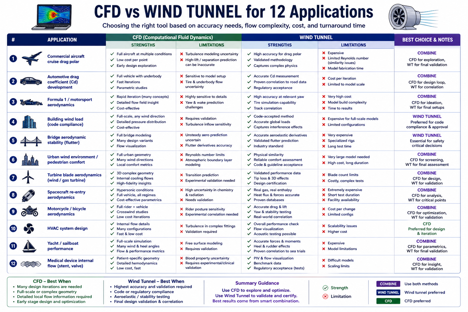
| Application | Recommended Primary Method | Role of Secondary Method | Rationale |
| Commercial aircraft cruise drag polar | Wind tunnel (low-speed + high-speed transonic) | CFD for parametric geometry exploration before tunnel entry; post-tunnel CFD extrapolation | FAA certification requires tunnel validation; drag count accuracy (1 drag count = 0.1% fuel burn) requires tunnel precision |
| Automotive drag coefficient (Cd) development | CFD (RANS k-ω SST) for parametric sweep; tunnel for final confirmation | Tunnel for final Cd validation and surface pressure measurement correlation | Automotive schedules require fast iteration; tunnel used for model validation and regulatory homologation data |
| Formula 1 / motorsport aerodynamics | CFD and tunnel in parallel (FIA regulated hours of both) | Each validates the other; CFD explores variants tunnel cannot test in regulated hours | Both required by regulations; CFD and tunnel capabilities are complementary in this high-performance, regulation-constrained environment |
| Building wind load (code compliance) | CFD (RANS or LES for tall buildings and complex terrain) | Tunnel for novel shapes or if CFD deviates from code simplified method by > 20% | Wind engineering codes (ASCE 7, Eurocode 1) accept CFD for most buildings; complex geometries and pedestrian wind comfort may require tunnel |
| Bridge aerodynamic stability (flutter) | Wind tunnel (section model tests) | CFD for flow visualization and pressure distribution around deck cross-section | Flutter is sensitive to nonlinear aeroelastic effects; tunnel section model test is industry standard for certification per AASHTO LRFD Bridge Design Specifications |
| Urban wind environment / pedestrian comfort | CFD (RANS LES for detailed urban flow) | Tunnel (boundary layer wind tunnel) for regulatory acceptance in some jurisdictions | CFD is standard for planning applications; London, Melbourne, and other cities now accept CFD from accredited firms; tunnel still preferred for complex urban canyons |
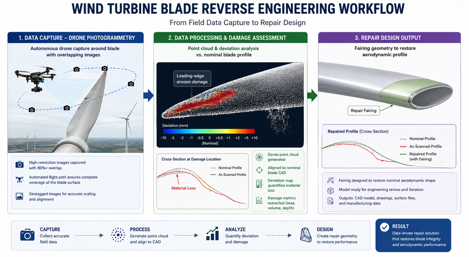
| Turbine blade aerodynamics (wind / gas turbine) | CFD (RANS for design; LES/DES for tip losses and separation) | Tunnel (cascade tunnel) for turbine aerodynamic validation; rotating rig for full performance map | CFD drives design; cascade tunnel validates profile loss at correct Re and Mach; rotating rig for efficiency map |
| Spacecraft re-entry aerodynamics | CFD (high-Mach RANS/DSMC for rarefied flow regimes) | Hypersonic wind tunnel for validation; ballistic range for high-Re transient | Physical testing at hypersonic conditions is extremely expensive and limited; CFD is primary tool with targeted tunnel validation |
| Motorcycle / bicycle aerodynamics | CFD (RANS) for geometry exploration; tunnel for athlete or rider positioning | Tunnel with mannequin or rider for realistic body position testing | Rider or athlete body position cannot be accurately captured in CAD; tunnel with real subject is necessary for final position optimization |
| HVAC system design | CFD (RANS) exclusively for most applications | No tunnel equivalent, CFD is the only practical tool at room or building scale | No wind tunnel can reproduce a complete building HVAC system at full scale; CFD is the only viable design tool |
| Yacht / sailboat performance | CFD (RANS) for hull resistance and appendage optimization | Towing tank for hull resistance validation; tunnel for upwind sail aerodynamics | Yacht performance involves two fluid domains (water + air); CFD and towing tank for hull; tunnel for sail aerodynamics |
| Medical device internal flow (stent, valve) | CFD (RANS, LES for blood flow with FSI) | Experimental flow loop with PIV for model validation | Physical wind tunnel irrelevant, internal physiological flows use experimental flow loops; CFD is primary design tool validated by PIV |
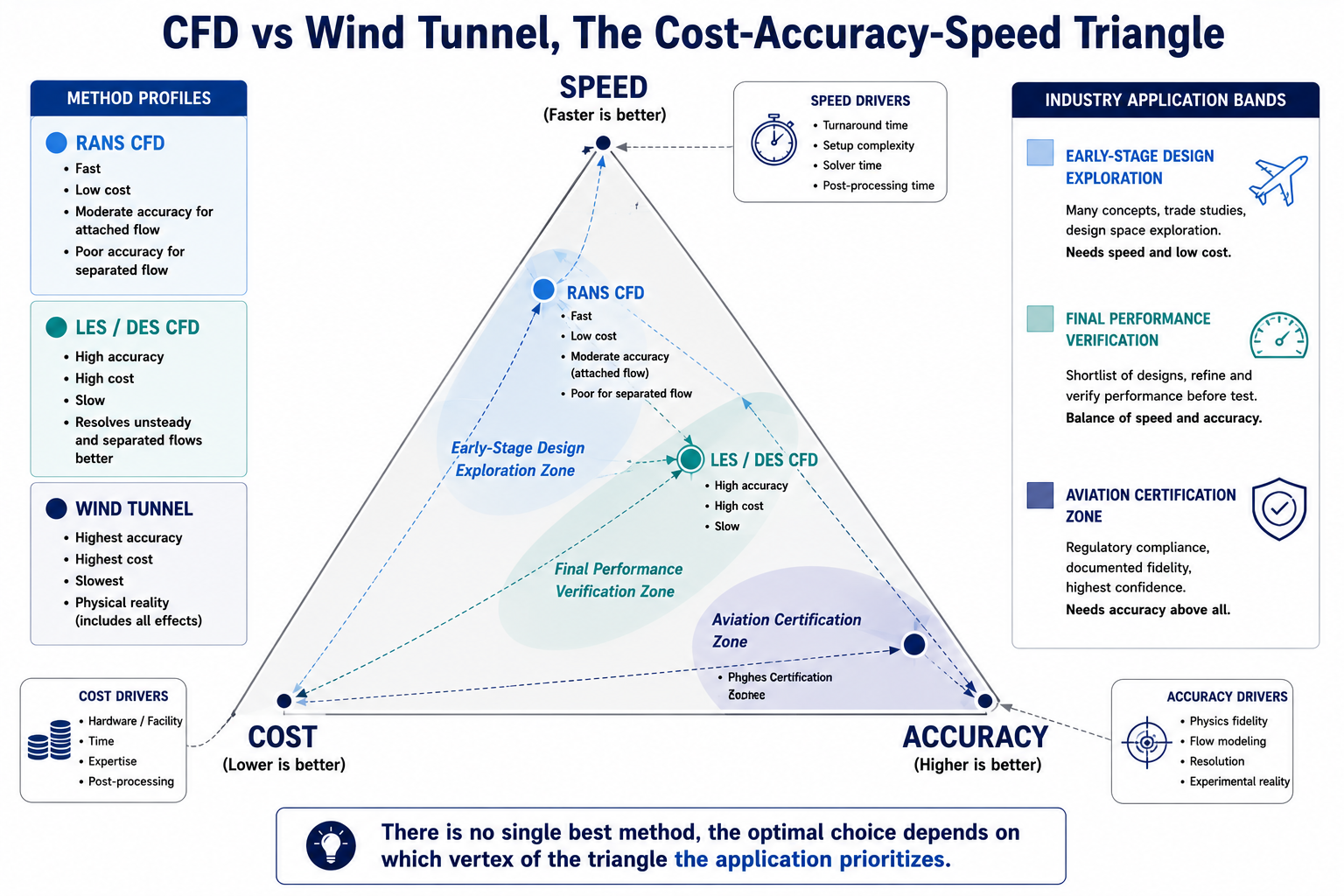
The Optimal Approach: CFD and Wind Tunnel as Complements
The premise of the article’s title, ‘which is better?’, contains a false dichotomy. In every demanding aerodynamic program, the optimal approach uses both methods in a structured workflow where each validates and extends the other. The question is not CFD or tunnel, but how to allocate the development program’s investment between the two to maximize the total aerodynamic knowledge gained per dollar spent.
The Modern Aerodynamic Development Workflow
The workflow that has evolved at leading aerospace and automotive organizations over the past two decades is:
- Early design exploration, CFD (RANS): Generate hundreds to thousands of geometry variants at low cost per run. Use parametric sweeps to identify the design space regions with the best aerodynamic performance. Screen out non-viable concepts before any physical hardware is built. RANS accuracy is sufficient at this stage because design decisions are relative (which direction to move the design) not absolute (what is the exact drag count).
- Down-selected design validation, CFD (higher fidelity): For the top 3 to 5 concepts identified in the RANS exploration, run higher-fidelity RANS with wall-resolved meshes or DES for configurations with suspected separation. Use CFD to identify risk areas, where separation is predicted, where CFD-to-tunnel correlation is likely to be poor, before committing to tunnel testing.
- Tunnel validation of CFD model, wind tunnel (targeted): Test a representative subset of configurations in the tunnel to validate the CFD model: typically 2 to 5 configurations that span the design space. The goal is not to measure every variant but to establish that the CFD model correctly predicts the relative aerodynamic differences between configurations at the accuracy required for design decisions. Once CFD is validated against the tunnel for this range of geometries, CFD predictions for intermediate configurations can be trusted.
- Final performance verification, wind tunnel: Test the final down-selected design at the highest fidelity available to establish the performance baseline for regulatory submission, homologation, or program record. This tunnel entry benefits from all the CFD-guided geometry optimization work, the design entering the tunnel is already near-optimum rather than a first-pass concept.
- Post-tunnel CFD extrapolation, CFD: Use the validated CFD model to explore configurations and conditions that the tunnel program did not cover: off-design conditions, sensitivity to manufacturing tolerances, rain and icing effects, different altitudes or speeds. The validated CFD model has earned the right to extrapolate beyond the tunnel test matrix.
Formula 1: The Regulated Hybrid as a Case Study
Formula 1 aerodynamic development is the most intensively studied example of the CFD-tunnel hybrid workflow, partly because it is regulated: the FIA Technical Regulations cap the number of CFD runs and wind tunnel hours each team can use per aerodynamic testing period, creating a constrained optimization problem where the allocation between CFD and tunnel has genuine financial consequences.
Under the 2023–2026 regulations, teams are allocated a token budget of aerodynamic testing time (ATT) divided between CFD runs and wind tunnel occupancy, with the highest-ranked teams receiving fewer tokens than lower-ranked teams (a competitiveness equalization mechanism). The leading teams operate 60-percent-scale wind tunnels in-house (the maximum permitted model scale) and high-performance CFD clusters consuming 20 to 50 megawatts of power, running hundreds of CFD simulations per week to explore geometry variants before committing tunnel time to the most promising concepts. Every tunnel session is preceded by a CFD campaign that has already identified the highest-performing configurations, tunnel time is not used for exploration but for validation and final performance quantification.
The F1 example illustrates the general principle: tunnel time is most valuable when it is used to validate a CFD model that has already converged on a high-performance design, not when it is used to explore the design space from scratch. The exploration is cheaper in CFD; the validation is more reliable in the tunnel.
Emerging Technologies: AI-Accelerated CFD and the Future Balance
The balance between CFD and wind tunnel testing is not static, it has been shifting toward CFD for 30 years as computational power has grown and CFD accuracy has improved, and it is accelerating further as machine learning and AI-accelerated CFD methods reduce the cost of high-fidelity simulation.
Neural network surrogate models, trained on databases of CFD results for a family of geometries, can predict aerodynamic forces and surface pressure distributions in milliseconds for new geometries within the training envelope. These surrogate models do not replace physics-based CFD but they compress the early-design exploration phase from days (RANS) to seconds (surrogate), enabling design space searches that are 100 to 1,000 times larger than RANS-based exploration. The leading F1 teams, automotive OEMs, and aerospace companies are investing heavily in surrogate model development, and the technology is beginning to reach industrial-scale maturity.
Physics-informed neural networks (PINNs) and neural operator methods (DeepONet, Fourier Neural Operators) represent a more fundamental change: neural network architectures that embed the Navier-Stokes equations as constraints, enabling them to solve fluid dynamics problems faster than traditional discretization methods while maintaining physical consistency. These methods are not yet mature for industrial aerodynamics at engineering Reynolds numbers, but the research trajectory suggests that within 5 to 10 years, they will challenge traditional RANS CFD for routine aerodynamic analysis.
The implication for the CFD-tunnel balance: as CFD cost decreases and accuracy increases, the threshold at which physical testing provides marginal value over CFD will continue to rise. Wind tunnels will remain essential for high-stakes final certification and for validating new CFD modeling approaches in new flow regimes. But the volume of tunnel testing in the design exploration phase will continue to decrease as CFD and AI-accelerated surrogates handle the exploration work more efficiently.
Frequently Asked Questions
Q: Is CFD replacing wind tunnels?
No. CFD is reducing the need for wind tunnel testing during design exploration, but it has not replaced wind tunnels for final validation or regulatory certification. Wind tunnels remain essential for certification, validating new designs, and testing complex separated flows where CFD accuracy is still limited.
Q: How accurate is CFD compared to a wind tunnel?
CFD can closely match wind tunnel results for attached aerodynamic flows, often predicting drag within 3–5% of measured values using well-validated RANS models. However, accuracy decreases for separated or highly turbulent flows, where advanced methods such as LES or DES—or wind tunnel testing—are typically required.
Q: What is the Reynolds number and why does it matter for CFD vs tunnel comparison?
The Reynolds number determines how fluid flows around an object by comparing inertial and viscous forces. Matching Reynolds number is essential because it ensures similar aerodynamic behavior between a model and the real product. CFD can simulate full-scale Reynolds numbers directly, while wind tunnel tests often require scaling corrections.
Q: What turbulence model should I use for aerodynamic CFD?
For most external aerodynamic applications, the k-ω SST turbulence model is the preferred choice because it provides reliable accuracy for attached and mildly separated flows. For highly separated, wake-dominated, or aeroacoustic problems, DES or LES is recommended to capture complex turbulent behavior more accurately.
Q: What are wind tunnel blockage corrections and why do they matter?
Wind tunnel blockage corrections compensate for the effect of the test model occupying part of the tunnel, which alters the airflow and can distort drag and lift measurements. Applying these corrections helps ensure the results represent real free-air conditions and improves the accuracy of CFD-to-test comparisons.
Q: When is wind tunnel testing still essential despite CFD capability?
Wind tunnel testing remains essential for regulatory certification, validating new or unconventional designs, and analyzing complex separated flows where CFD uncertainty is high. It also provides experimental data needed to validate simulation models and improve confidence in safety-critical engineering decisions.
Conclusion:
The answer to ‘CFD vs wind tunnel, which is better?’ is the same as the answer to ‘hammer vs screwdriver, which is better?’ The question is not which is superior in the abstract but which is the right tool for the specific task, and whether the task requires both. CFD is faster, cheaper, provides more complete flow field information, and has no Reynolds number scaling problem. Wind tunnels measure real fluid physics with no turbulence modeling uncertainty, provide the reference data that validates CFD, and remain the regulatory standard for final aerodynamic certification in aviation. Neither has made the other obsolete, and neither will in the foreseeable future.
The technical competency that actually differentiates engineering teams in aerodynamic development is not expertise in one method or the other, it is the judgment to deploy each method where it is most reliable and most cost-effective, and to structure the program so that CFD and tunnel data reinforce each other rather than competing. A CFD program without tunnel validation is built on uncertain foundations.
A tunnel program without CFD to guide the test matrix and interpret the data is exploring the design space inefficiently. The teams that consistently produce the most aerodynamically refined products, the lowest-drag aircraft, the most competitive race cars, the most efficient wind turbine blades, are the ones that have mastered the integration of both tools into a single coherent development methodology.
The tables in this article, the 12-parameter comparison, the turbulence model hierarchy, the wind tunnel correction reference, and the 12-application decision table, provide the technical framework for making these deployment decisions correctly. The underlying principle is simple: understand what each method can and cannot predict reliably, use CFD where its advantages are decisive, use the tunnel where physical reality matters more than modeling assumptions, and always validate the CFD model against tunnel data before trusting it for extrapolation.
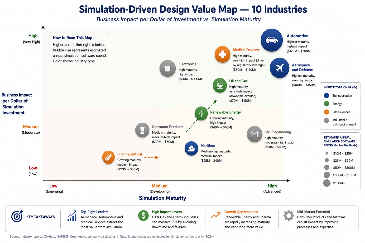
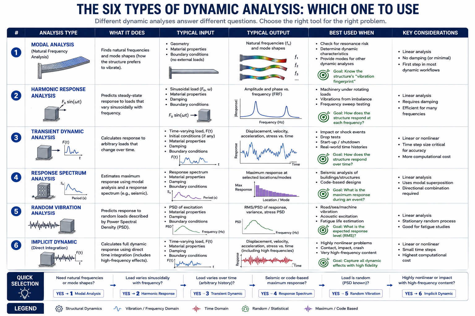
Deepen your simulation knowledge with our guides on why simulation fails, the FEA preprocessing checklist, static vs dynamic analysis, and how leading industries deploy simulation-driven design to cut development cost and improve product performance.