Introduction: Why the Old Engineering Workflow Is No Longer Enough
For decades, the mechanical engineering workflow looked the same: sketch an idea, build a CAD model, hand it to a simulation specialist, wait days for results, fix errors, and repeat. It worked, but it was slow, expensive, and often caught mistakes far too late.
In 2026, something fundamental has changed. AI workflow in mechanical engineering is replacing that slow, linear process with something faster, smarter, and more connected, from the first concept sketch all the way through simulation and validation.
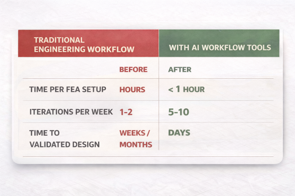
Engineers at companies like BMW, Hyundai, and Airbus are already using AI-driven design simulation to cut prototype cycles by 40–60%. Teams that once needed specialist CAE analysts to run FEA studies are now letting AI FEA automation handle the setup, meshing, and post-processing, while their engineers focus on the decisions that actually matter.
Whether you’re a mechanical engineer, a product designer, or a team lead looking to modernise your processes, this guide will show you exactly how AI workflow in mechanical engineering works, from the first design stage to final simulation validation, and which tools and techniques will deliver real results.
| Quick Answer, What Is AI Workflow in Mechanical Engineering? AI workflow in mechanical engineering refers to the use of artificial intelligence tools, including generative design AI, AI FEA automation, and AI-driven design simulation, to automate, accelerate, and optimise each stage of the engineering process, from concept design through CAD modelling, structural analysis, CFD, and digital validation. It replaces slow, manual sequences with AI-assisted design and simulation workflow pipelines that give engineers faster feedback, fewer errors, and more design options. |
| 40-60% | Reduction in design cycle time reported by companies using generative design AI and AI-driven simulation (Autodesk, PTC 20251) |
| $17.97B | Global simulation software market size in 2025, growing at 12.1% CAGR, AI is the primary driver (CAE Assistant, 2025) |
| 10–100× | Speed increase for 3D physics performance predictions using Ansys SimAI vs traditional FEA solvers |
What Does an AI Workflow in Mechanical Engineering Actually Look Like?
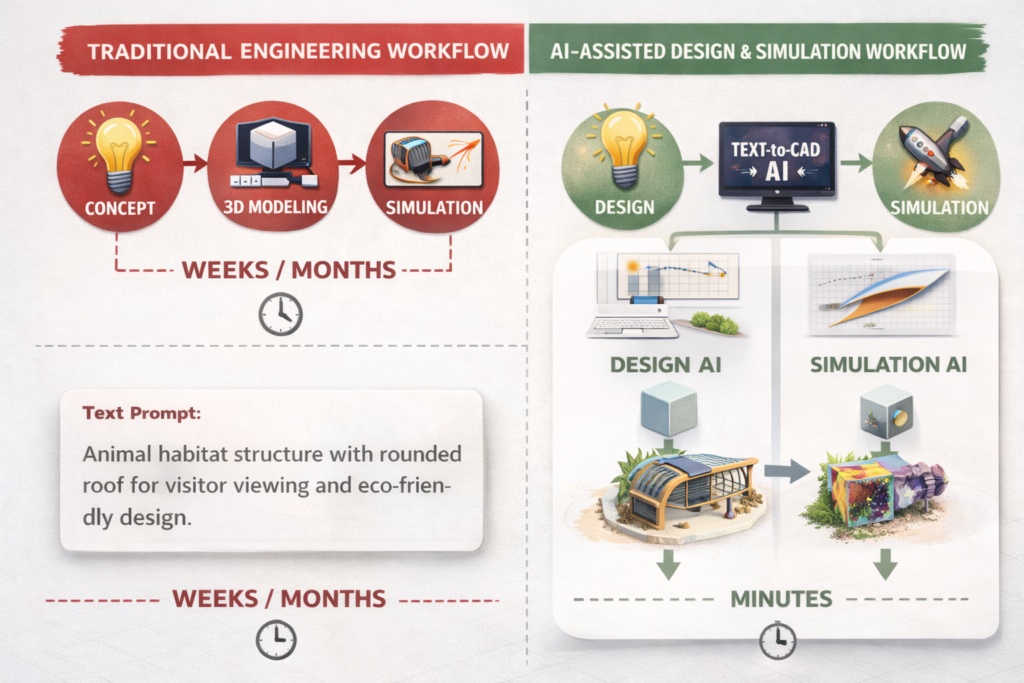
Before diving into the tools and techniques, it helps to understand how an AI workflow in mechanical engineering is structured, and how it differs from a traditional process.
In a traditional workflow, each stage is isolated: a designer creates the CAD model, passes it to a simulation analyst, who sets up the study, runs it overnight, and reports back. Then the designer revises, and the cycle repeats. It’s slow, siloed, and often means simulations only happen at the end, when changes are most expensive.
An AI CAD workflow 2025 breaks down those silos. AI mechanical design tools provide real-time feedback during modelling. AI-driven design simulation runs alongside the design, not after it. AI engineering tools automate the repetitive parts, meshing, post-processing, documentation, so engineers spend their time on judgement and innovation.
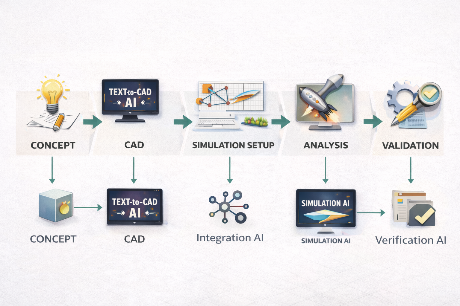
The 5 Stages of an AI-Powered Engineering Workflow
- Stage 1 Conceptual Design: AI generates and evaluates multiple design concepts based on requirements. Generative design AI tools like Autodesk Fusion propose geometry optimised for weight, strength, and manufacturability.
- Stage 2 CAD Modelling: AI mechanical design assistants (including Claude AI for engineering) accelerate modelling, write scripts, generate parameters, and check design logic in real time.
- Stage 3 Simulation Setup: AI FEA automation handles meshing, boundary conditions, material assignment, and solver configuration, tasks that once took specialist hours.
- Stage 4 Analysis & Optimisation: AI-powered CAE tools run parametric studies, predict failure modes, and recommend design changes, with surrogate model engineering delivering results in seconds.
- Stage 5 Validation & Documentation: Digital twin AI enables real-time comparison between simulation and physical test data. AI generates technical reports and documentation automatically.
Stage 1–2: AI in the Design Phase, From Concept to CAD
The design phase is where AI workflow in mechanical engineering delivers its most immediate, visible impact. Let’s walk through what’s possible today.
Generative Design AI, More Options, Less Manual Work
Generative design AI doesn’t just help you draw a part, it proposes the part. You define the constraints: applied loads, fixed mounting points, material choices, and weight targets. The AI generates dozens of optimised geometry variations, each meeting your requirements in a different way.
Tools like Autodesk Fusion generative design and PTC Creo AI have made this mainstream. Engineers report 40–60% reductions in design cycle time and lighter, stronger components that human designers rarely arrive at intuitively.
This is AI design optimisation working at its most powerful, the AI explores a design space that would take months to map manually, and does it in hours.
AI-Assisted CAD Modelling, Smarter, Faster, Error-Free
Beyond generative design, AI-assisted design and simulation workflow tools are changing how individual engineers model parts day to day. Claude AI for engineering, used alongside CAD platforms, can write AutoLISP scripts, generate parametric feature lists, check design logic, and produce technical documentation in minutes.
SolidWorks AURA, Onshape AI Advisor, and MecAgent all operate directly inside CAD environments, offering real-time suggestions, automating constraints, and flagging potential issues before they become simulation failures. This is AI CAD workflow 2025 in daily practice, not a future concept, but a working reality.
| Example AI Prompt for Engineering Design Brief (Use with Claude): “You are a senior mechanical engineer. I am designing an aluminium bracket that must support 2kN downward load with a 3× safety factor, mounted to a steel frame with 4 × M8 bolts. Wall thickness must be 4–6mm. Suggest key design features, critical dimensions, and potential failure modes I should simulate. Format as a structured engineering brief.” Result: Claude returns a complete design brief with dimensions, failure mode analysis, and simulation priority list, ready to use as your CAD and FEA starting point. |
How to Use AI for Mechanical Engineering Simulation | Stage 3 to 4
Simulation has historically been the biggest bottleneck in product development. Complex AI tools for FEA and CFD studies can take hours or days to set up and run. AI simulation changes this dramatically.
AI FEA Automation, End the Setup Bottleneck
AI FEA automation tackles the two biggest problems in structural analysis: setup time and solve time. On the setup side, AI tools handle meshing, contact definitions, boundary conditions, and material assignment automatically, tasks that once required a specialist engineer and several hours. On the solve side, surrogate model engineering, where a machine learning model is trained on previous simulation data, delivers near-instant predictions instead of waiting for the full solver to run.
Carnegie Mellon University’s TAG U-NET (2025) demonstrated that AI can predict stress and deformation fields directly from CAD geometry, replacing costly FEA iterations in early design stages with real-time feedback. This is AI simulation engineering 2025 at the research frontier, and it’s reaching commercial tools rapidly.
AI CFD Optimisation, Faster Fluid Dynamics
Computational Fluid Dynamics (CFD) has always been the most computationally expensive simulation type, fine meshes, long solve times, massive compute bills. AI-powered CAE tools like SimScale and Ansys SimAI are changing that equation by using machine learning to predict flow behaviour based on geometry patterns learned from thousands of previous simulations.
The result: AI tools for FEA and CFD can now run parametric CFD sweeps, varying inlet velocity, geometry, or boundary conditions, in a fraction of the traditional time. Convion’s team at HD Hyundai used this approach to solve a complex hydrogen ejector pump optimisation problem that would have taken months with traditional CFD, completing it in weeks.
Surrogate Models and Physics-Informed Neural Networks
The cutting edge of AI-driven design simulation involves physics-informed neural networks (PINNs) and surrogate models. A surrogate model engineering approach trains a lightweight AI on high-fidelity simulation data, then uses that trained model to predict results for new design variants in milliseconds, without running the full solver.
Platforms like Ansys SimAI, Altair HyperWorks AI, and Siemens NX are all integrating this capability. The practical result: engineers can explore 50–100 design variants per session instead of 3–5. That’s the AI design optimisation multiplier effect.
Digital Twin AI: Closing the Loop Between Virtual and Physical
Digital twin AI takes simulation one step further. A digital twin is a live, continuously updated simulation model of a physical product or system. AI processes real-world sensor data from the physical asset and updates the simulation model in real time, enabling predictive maintenance, performance monitoring, and design validation against actual operating conditions.
For mechanical engineering teams, digital twin AI means your simulation doesn’t end when the product ships. It becomes an ongoing engineering resource that gets smarter with every operating hour, a critical capability in industries like aerospace, energy, and industrial machinery.

Best AI Tools for Mechanical Engineers 2026 Complete Comparison
Here is a clear breakdown of the best AI tools for mechanical engineers 2026 across the full workflow, from design to simulation.
| AI Tool | Workflow Stage | Key AI Capability | Best For |
| Autodesk Fusion generative design | Design | Generative design, topology optimisation, cloud CAM | Full product development teams |
| PTC Creo AI | Design + Sim | AI generative design, real-time simulation, thermal physics | Complex mechanical systems |
| Claude AI for engineering | Design + Docs | Prompt engineering, scripts, design briefs, FEA setup notes | All engineers, any CAD platform |
| Ansys SimAI | Simulation | AI-powered CAE, 3D physics predictions 10–100× faster | FEA/CFD speed optimisation |
| SimScale AI | Simulation | Cloud-native AI CFD and FEA, guided simulation setup | Teams without specialist CAE |
| Altair HyperWorks | Simulation | AI surrogate models, topology optimisation AI, auto-meshing | Optimisation-heavy workflows |
| Siemens NX / Teamcenter | PLM + Sim | Digital twin AI, AI knowledge management, PLM automation | Large engineering organisations |
| SOLIDWORKS AURA | CAD | Contextual AI suggestions, automated constraints, feature recognition | SolidWorks daily users |
Step-by-Step: Building Your AI-Assisted Design and Simulation Workflow
Here is a practical framework for implementing AI workflow in mechanical engineering, whether you’re starting from scratch or upgrading an existing process. This is the AI-assisted design and simulation workflow used by leading engineering teams today.
- Define your design requirements clearly. Write a structured requirements document. Use Claude AI for engineering to help: describe your part’s function, loads, materials, manufacturing method, and applicable standards. A clear requirements document is the foundation of any successful AI-driven design simulation workflow.
- Generate design concepts with AI. Feed your requirements into a generative design AI tool. Let Autodesk Fusion generative design or PTC Creo AI propose geometry options. Review 5–10 variants against your requirements before committing to one direction.
- Build and refine your CAD model. Use your chosen CAD platform with AI assistance. Write scripts, check parameters, and generate documentation with Claude AI for engineering. This is your AI CAD workflow 2025 in action.
- Set up simulation with AI automation. Import your model into SimScale AI or Ansys. Let AI FEA automation handle meshing, contact definitions, and boundary conditions. Validate the setup with a quick sanity check before running. Explore more on this: Prompt Engineering in Mechanical Engineering
- Run parametric studies, not single runs. Use AI tools for FEA and CFD to run sweeps of key parameters, wall thickness, fillet radius, load magnitude, in parallel. Surrogate model engineering makes this practical even on modest hardware.
- Interpret results with AI assistance. Ask Claude AI for engineering to help interpret your simulation output. Describe the results and ask: ‘What does this stress concentration indicate? What design changes should I prioritise?’ This turns AI simulation results into actionable engineering decisions.
- Connect to your digital twin. For products that will be monitored in service, connect your validated simulation model to your digital twin AI platform. This closes the loop between virtual AI-driven design simulation and real-world performance.
Common Mistakes Teams Make When Adopting AI Engineering Workflows
Adopting AI engineering tools isn’t just a technology decision, it’s a process change. These are the mistakes that slow teams down, and how to avoid them.
| Mistake 1: Starting Too Big Trying to overhaul the entire AI workflow in mechanical engineering overnight creates chaos. Start with one bottleneck, like AI FEA automation for a single part family, prove the value, then expand. |
| Mistake 2: Poor Data Quality Going In Surrogate model engineering and AI simulation tools are only as good as the data they’re trained on. Messy, inconsistent, or incomplete simulation data produces unreliable AI predictions. Clean your data first. |
| Mistake 3: Treating AI as a Replacement, Not an Augmentation AI doesn’t replace engineering judgement, it amplifies it. AI-powered CAE tools accelerate simulation but still require an engineer to validate results, interpret failure modes, and make design decisions. Engineers who expect AI to ‘just solve it’ are consistently disappointed. |
| Mistake 4: Skipping Prompt Engineering for AI Tools Whether you’re using Claude AI for engineering or writing prompts for a generative design AI tool, vague inputs give vague outputs. Learning to write precise, structured prompts is the single biggest lever on the quality of your AI-assisted design and simulation workflow output. |
| Mistake 5: Ignoring the Digital Twin Layer Teams that stop at simulation miss the compounding value of digital twin AI. Connecting your validated models to real-world operational data turns a one-off project into a continuously improving engineering asset. |
Pro Tips: Getting Expert Results from AI Engineering Workflows
Expert Tips for AI Workflow in Mechanical Engineering
- Build a simulation-first culture: Use AI FEA automation to make simulation fast enough that it happens at every design stage, not just at the end. This is the hallmark of teams with mature AI workflow in mechanical engineering practices.
- Layer Claude with specialist tools: Claude AI for engineering is your briefing, documentation, and prompt refinement layer. Specialist tools like Ansys or SimScale handle the physics. Using both together creates a complete AI-assisted design and simulation workflow.
- Use surrogate models for DOE: Design of Experiments (DOE) with surrogate model engineering is 10–100× faster than running full simulations at every point. Build the surrogate, sweep the parameter space, then validate only the top candidates with high-fidelity AI simulation.
- Mandate prompt engineering training: Every engineer using AI engineering tools should understand how to write effective prompts. Even a half-day training session on structured prompt writing for AI-driven design simulation delivers immediate, measurable productivity gains.
- Set AI simulation guardrails: Establish validation checklists for AI-powered CAE outputs. Even when AI FEA automation handles the setup, a 5-point engineer review checklist catches the errors AI tools miss, material assignments, unit inconsistencies, boundary condition oversights.
- Track your AI ROI: Measure the time saved per simulation cycle before and after introducing AI tools for FEA and CFD. Concrete data builds internal buy-in and justifies investment in more capable platforms.
Conclusion: The Engineers Who Adopt This Now Will Lead Their Industries
AI workflow in mechanical engineering is not coming, it’s here. The engineers and teams who are building AI-assisted design and simulation workflow practices today are already seeing 40–60% faster design cycles, more design options explored, fewer late-stage surprises, and better-performing products.
The full stack, generative design AI for concept, AI CAD workflow 2025 for modelling, AI FEA automation and AI tools for FEA and CFD for analysis, and digital twin AI for validation, is available, proven, and accessible right now.
The only question is where you start. Our recommendation: pick one bottleneck in your current workflow, introduce one AI engineering tools solution, measure the result, and build from there. The teams who start small and iterate fast are the ones who build the most effective AI-driven design simulation pipelines.
Frequently Asked Questions
Q1. What is AI workflow in mechanical engineering?
AI workflow in mechanical engineering refers to using artificial intelligence tools throughout the entire engineering process, from generative design AI in the concept phase, through AI FEA automation and AI tools for FEA and CFD in simulation, to digital twin AI for post-deployment validation. It replaces slow, manual, siloed processes with connected, intelligent pipelines that give engineers faster feedback, more design options, and fewer late-stage errors. In 2025, this is the defining capability separating high-performing engineering teams from the rest.
Q2. How does AI automation improve FEA simulations?
AI FEA automation improves structural simulations in two key ways. First, it automates the most time-consuming setup tasks: meshing, boundary condition application, contact surface definition, and material assignment, reducing specialist setup time from hours to minutes. Second, surrogate model engineering trains a machine learning model on existing simulation data to deliver near-instant predictions for new design variants, cutting solve time from hours to seconds. Tools like Ansys SimAI can predict 3D physics performance 10–100× faster than traditional solvers.
Q3. What are the best AI tools for mechanical engineers in 2025?
The best AI tools for mechanical engineers 2025 cover every workflow stage. For design: Autodesk Fusion generative design and PTC Creo AI. For simulation: Ansys SimAI and SimScale AI for AI tools for FEA and CFD. For documentation, scripting, and AI engineering briefs: Claude AI for engineering. For optimisation loops: Altair HyperWorks with topology optimisation AI. The right combination depends on your workflow bottleneck.
Q4. What is a surrogate model in engineering simulation?
A surrogate model engineering approach involves training a lightweight machine learning model on high-fidelity simulation data (FEA or CFD results). Once trained, the surrogate can predict simulation outcomes for new design variants in milliseconds, rather than requiring the full physics solver to run. This makes it practical to explore 50–100 design variants per session. Physics-informed neural networks (PINNs) take this further by embedding physical laws directly into the model for higher accuracy across a wider parameter range.
Q5. How is a digital twin different from a simulation model?
A traditional simulation model is a static, one-time analysis. A digital twin AI is a live, continuously updated simulation that receives real-time data from the physical asset and updates its predictions accordingly. While simulation gives you a validated design, digital twin AI gives you ongoing operational insight, enabling predictive maintenance, performance monitoring, and in-service design improvements. It’s the final stage of a mature AI workflow in mechanical engineering pipeline.
Q6. Can AI replace FEA engineers?
No, and this is important. AI FEA automation handles the repetitive, time-consuming parts of simulation setup and processing. But engineering judgement, interpreting results, identifying failure modes, making design trade-offs, and validating AI outputs, still requires an experienced engineer. The correct framing is that AI engineering tools amplify what engineers can do, not replace them. Teams using AI-powered CAE tools are producing better work faster, with the same or smaller headcount.
Q7. How do I start implementing an AI workflow in my engineering team?
Start small and focused. Identify your single biggest workflow bottleneck, likely either FEA setup time or design iteration speed, and introduce one AI-assisted design and simulation workflow tool to address it. Measure before and after. Use Claude AI for engineering to accelerate documentation and prompt refinement from day one (it’s free to start). Once you’ve proven ROI on one stage, expand to the next. Full AI workflow in mechanical engineering adoption happens stage by stage, not all at once.
| This article cites verified 2025–2026 industry data from Ansys, SimScale, PTC, Autodesk, and peer-reviewed sources. All tool claims are sourced from official product pages and independent engineering publications. It is written for , and reviewed by, practising mechanical engineers. |
Leave a Reply