Introduction: The Power of Virtual Testing
Finite Element Analysis (FEA) has become an indispensable tool in modern engineering, allowing designers to predict how products will behave under real-world conditions before they’re manufactured. This powerful simulation technique can identify potential failures, optimize designs, and reduce development costs by minimizing the need for physical prototypes and testing.
However, many engineers and project managers struggle with understanding when FEA is necessary, what types of analysis are available, and how to implement FEA effectively in their development process. This comprehensive guide will help you make informed decisions about incorporating FEA into your engineering projects.
What is Finite Element Analysis?
Finite Element Analysis is a computational method that breaks down complex structures into smaller, simpler elements to analyze their behavior under various conditions. By solving mathematical equations for each element and combining the results, FEA provides detailed insights into how structures respond to forces, heat, vibrations, and other physical phenomena.
The FEA Process:
- Preprocessing: Creating the model, defining materials, and setting up boundary conditions
- Solving: The computer calculates the response of each element
- Post-processing: Visualizing and interpreting the results
Types of FEA Analysis:
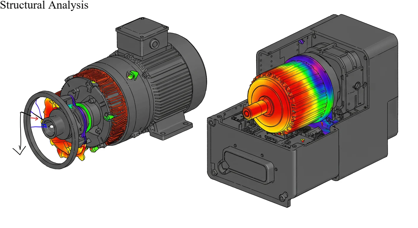
- Structural Analysis: Stress, strain, and displacement under mechanical loads
- Thermal Analysis: Heat transfer and temperature distribution
- Modal Analysis: Natural frequencies and vibration modes
- Fluid Dynamics: Fluid flow and pressure distribution
- Fatigue Analysis: Prediction of failure under cyclic loading
- Buckling Analysis: Stability under compressive loads
When Your Project Needs FEA
Critical Safety Applications
FEA is essential when failure could result in injury, property damage, or loss of life. Industries such as aerospace, automotive, medical devices, and structural engineering rely heavily on FEA to ensure safety margins are adequate.
Examples of Critical Applications:
- Aircraft components subjected to extreme loads and temperatures
- Automotive crash structures and safety systems
- Medical implants that must withstand cyclic loading
- Pressure vessels operating under high pressure and temperature
- Structural elements in buildings and bridges
High-Value Projects
When development costs are high or failure would be extremely expensive, FEA provides valuable risk mitigation. The cost of simulation is typically a small fraction of the cost of physical testing or product failure in the field.
Cost-Benefit Considerations:
- Projects with expensive prototyping and testing requirements
- Products with long development cycles where late-stage changes are costly
- High-volume production where small improvements yield significant savings
- Custom or one-off designs where testing isn’t practical
Performance Optimization Requirements
FEA excels at identifying optimization opportunities that aren’t obvious through traditional design methods. This is particularly valuable in competitive industries where performance advantages translate to market success.
Optimization Scenarios:
- Weight reduction while maintaining strength requirements
- Improving thermal management in electronic devices
- Minimizing vibration and noise in mechanical systems
- Optimizing flow characteristics in fluid systems
- Maximizing efficiency in rotating machinery
Complex Loading Conditions
When parts experience complex combinations of loads, temperatures, or environmental conditions, FEA provides insights that simple hand calculations cannot achieve.
Complex Loading Examples:
- Components subjected to multiple load paths simultaneously
- Parts experiencing thermal cycling and mechanical stress
- Structures under dynamic or impact loading
- Systems with significant geometric nonlinearities
- Assemblies with complex contact interactions
Types of FEA and Their Applications
Structural Analysis
The most common type of FEA, structural analysis determines how parts deform and what stresses develop under mechanical loads.
Linear Static Analysis:
- When to Use: Small deformations, linear material behavior, steady loads
- Applications: Basic strength verification, deflection calculations
- Benefits: Fast computation, straightforward interpretation
- Limitations: Cannot handle large deformations or nonlinear effects
Nonlinear Analysis:
- When to Use: Large deformations, material plasticity, contact problems
- Applications: Crash analysis, forming simulations, rubber components
- Benefits: Accurate representation of real-world behavior
- Limitations: More complex setup, longer computation times
Thermal Analysis
Thermal FEA predicts temperature distributions and heat flow through structures, critical for managing thermal stresses and ensuring proper operation.
Steady-State Thermal Analysis:
- Applications: Electronics cooling, heat sink design, insulation effectiveness
- Key Outputs: Temperature distribution, heat flux, thermal gradients
- Design Insights: Hot spot identification, cooling optimization
Transient Thermal Analysis:
- Applications: Startup/shutdown cycles, thermal shock analysis
- Key Outputs: Temperature vs. time, thermal cycling effects
- Design Insights: Thermal stress development, cool-down strategies
Modal Analysis
Modal analysis identifies natural frequencies and mode shapes, essential for avoiding resonance problems and designing for dynamic stability.
When Modal Analysis is Critical:
- Rotating machinery operating near critical speeds
- Structures subjected to dynamic loading
- Systems requiring vibration isolation
- Parts that must avoid specific frequency ranges
Key Design Insights:
- Natural frequency identification
- Mode shape visualization
- Damping requirements
- Stiffness optimization strategies
Fatigue Analysis
Fatigue analysis predicts how long parts will last under cyclic loading, crucial for components that experience repeated stress cycles.
Fatigue Analysis Applications:
- Automotive suspension components
- Aircraft structural elements
- Rotating machinery shafts
- Pressure vessel nozzles
- Electronic component solder joints
Fatigue Analysis Benefits:
- Life prediction for maintenance scheduling
- Identification of crack initiation sites
- Optimization of stress concentrations
- Material selection guidance
Implementing FEA in Your Development Process
Early-Stage Design Validation
Incorporating FEA early in the design process provides maximum value by identifying issues when changes are still inexpensive to implement.
Early-Stage FEA Benefits:
- Concept feasibility verification
- Material selection guidance
- Preliminary sizing and optimization
- Risk identification and mitigation
Design Optimization
FEA enables systematic design optimization that would be impractical with physical testing alone.
Optimization Strategies:
- Parametric Studies: Varying design parameters to understand sensitivities
- Topology Optimization: Finding optimal material distribution
- Shape Optimization: Refining geometry for improved performance
- Multi-objective Optimization: Balancing competing requirements
Virtual Testing and Validation
FEA can supplement or replace physical testing in many scenarios, reducing development time and cost.
Virtual Testing Advantages:
- Test conditions that are difficult or dangerous to replicate physically
- Evaluate multiple design variants quickly
- Investigate failure mechanisms in detail
- Reduce the number of physical prototypes required
Common FEA Mistakes and How to Avoid Them
Inadequate Model Validation
One of the most serious mistakes is using FEA results without proper validation against known solutions or experimental data.
Validation Best Practices:
- Compare results to analytical solutions when available
- Perform mesh convergence studies
- Validate against experimental data or previous designs
- Check results for physical reasonableness
Poor Mesh Quality
The finite element mesh is the foundation of any FEA simulation. Poor mesh quality leads to inaccurate results and convergence problems.
Mesh Quality Guidelines:
- Use appropriate element types for the physics being analyzed
- Refine mesh in high-stress regions
- Maintain good aspect ratios and avoid highly distorted elements
- Perform mesh convergence studies to ensure adequate refinement
Inappropriate Boundary Conditions
Boundary conditions must accurately represent the real-world constraints and loading conditions.
Boundary Condition Best Practices:
- Carefully consider how parts are actually supported and loaded
- Avoid over-constraining the model
- Use appropriate load distribution methods
- Consider thermal expansion effects in constrained systems
Ignoring Material Nonlinearities
Many materials exhibit nonlinear behavior, especially at high stress levels or temperatures.
Material Modeling Considerations:
- Use appropriate material models for the loading conditions
- Consider temperature effects on material properties
- Account for strain rate sensitivity when applicable
- Validate material models against test data
Building FEA Capabilities
In-House vs. Outsourced FEA
Organizations must decide whether to develop internal FEA capabilities or outsource analysis work.
In-House FEA Advantages:
- Greater control over analysis timing and priorities
- Better integration with design process
- Accumulated knowledge and experience
- Ability to perform iterative optimization
Outsourced FEA Advantages:
- Access to specialized expertise
- No capital investment in software and hardware
- Scalable capacity for project peaks
- Independent validation of critical analyses
Training and Skill Development
Successful FEA implementation requires ongoing investment in training and skill development.
Essential FEA Skills:
- Understanding of fundamental mechanics and physics
- Software-specific training and certification
- Post-processing and results interpretation
- Experimental validation techniques
Software Selection Criteria
Choosing the right FEA software depends on your specific needs, budget, and organizational capabilities.
Key Selection Factors:
- Types of analysis required
- Integration with CAD systems
- Ease of use and learning curve
- Technical support and training availability
- Total cost of ownership
Future Trends in FEA
Cloud-Based Simulation
Cloud computing is making high-performance FEA more accessible to smaller organizations and enabling new collaborative workflows.
AI and Machine Learning Integration
Artificial intelligence is beginning to automate mesh generation, optimize solver settings, and interpret results, making FEA more accessible to non-experts.
Real-Time Simulation
Advances in computing power and algorithms are enabling real-time FEA for interactive design optimization and virtual reality applications.
Multiphysics Integration
Modern products often involve complex interactions between structural, thermal, electromagnetic, and fluid phenomena, driving demand for integrated multiphysics simulation.
Conclusion
Finite Element Analysis is a powerful tool that can significantly improve product quality, reduce development costs, and accelerate time to market when properly implemented. The key to success lies in understanding when FEA adds value, choosing appropriate analysis types, and following best practices for model development and validation.
Whether your project involves ensuring safety-critical performance, optimizing designs for competitive advantage, or reducing development risk, FEA can provide the insights needed to make informed engineering decisions. The investment in FEA capabilities—whether in-house or through partnerships—often pays for itself many times over through improved products and reduced development cycles.
At SimuTecra, we specialize in providing comprehensive FEA services across all major analysis types and industries. Our experienced team can help you determine when FEA is beneficial for your projects and provide the analysis and insights needed to optimize your designs. Contact us today to discuss how FEA can accelerate your product development and improve your competitive position.