What to Include in an RFQ for CAD Drafting Services (With a Free Template)
Most bad CAD drafting projects do not fail during production. They fail during procurement. Specifically, they fail because the Request for Quotation that kicked off the vendor selection process was vague, incomplete, or missing the technical details that drafting firms need to price work accurately and deliver it correctly.
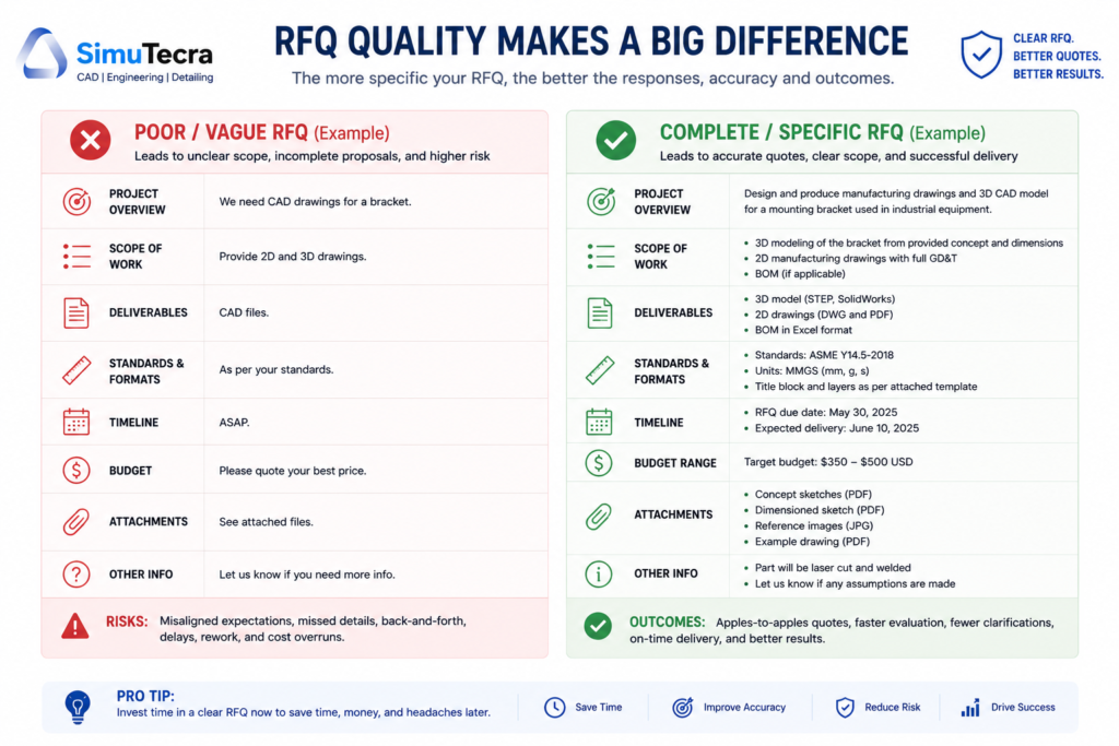
An RFQ for CAD drafting services is not a general services inquiry. It is a technical procurement document. When done well, it compresses your vendor selection process, produces comparable quotes you can actually evaluate side by side, protects you contractually, and sets the production relationship up for success from day one. When done poorly, it produces wildly different quotes that are impossible to compare, drawing output that does not match your standards, and revision cycles that inflate your final cost far above the original estimate.
This guide covers every element that belongs in a professional RFQ for CAD drafting services. It explains why each element matters, what information to include, and what happens when you leave it out. At the end, you will find a complete, ready-to-use RFQ template you can adapt for your own projects, whether you are procuring architectural drawings, mechanical detailing, structural shop drawings, BIM deliverables, or PDF-to-CAD conversion work.

1. RFQ vs RFP vs RFI: Which Document Do You Actually Need?
Before you write a single line of your document, you need to know which type of procurement document fits your situation. Sending the wrong one wastes your time and the vendor’s.
| Document | Full Name | Use When | Primary Question Asked |
|---|---|---|---|
| RFI | Request for Information | You are exploring the market, gathering general information about what CAD drafting services exist and what capabilities providers have. No pricing involved. | ‘What services do you offer and what capabilities do you have?’ |
| RFQ | Request for Quotation | You know exactly what you need (drawing type, quantity, standards, format) and you need vendors to quote a price. Scope is defined, price is the primary variable. | ‘What will it cost to produce these specific deliverables to these specific requirements?’ |
| RFP | Request for Proposal | Your project is complex or open-ended, and you need vendors to propose a methodology, team structure, and approach alongside pricing. Common for large or multi-phase CAD projects. | ‘How would you approach this project, with what team, on what timeline, at what cost?’ |
For most CAD drafting procurement, an RFQ is the right document. You know what you need (a set of mechanical drawings, an architectural permit package, a BIM model to LOD 300), and you need comparable quotes from qualified vendors. The RFQ is the workhorse of technical drafting procurement.
When to use an RFP instead: If your project involves significant design input from the drafter, multi-discipline coordination over several months, or you genuinely do not know the best approach and want vendors to propose solutions, the RFP gives you more flexibility. The cost is a longer, more complex procurement process.
When to start with an RFI: If you are evaluating the outsourced CAD market for the first time, want to understand what capabilities are available, or are building a pre-qualified vendor list before running a formal RFQ, an RFI is a lower-commitment first step.
2. Why Most CAD Drafting RFQs Fail
Research across the procurement literature and direct practitioner experience consistently shows that CAD drafting RFQs fail in the same predictable ways. Understanding these failure patterns is the fastest path to writing one that does not.
- Scope described in output terms, not input terms: Saying ‘we need 10 drawings’ tells a vendor almost nothing useful. It does not tell them what type of drawings, what level of detail, what source material you are providing, what standards the output must meet, or what software format you need. Without this, quotes are guesses.
- Drawing standards not specified: Most RFQs for drafting services do not mention the drawing standard, layer convention, or annotation requirements the output must meet. The vendor’s default and your requirement may be completely different. This is discovered, expensively, after the first deliverable.
- Revision terms left undefined: How many revision rounds are included? What counts as a minor revision versus a scope change? What is the billing rate for out-of-scope changes? Leaving this undefined turns every revision cycle into a potential dispute.
- File format and software not stated: ‘Send us the CAD files’ is not a deliverable specification. DWG, DXF, STEP, IGES, IFC, PDF, native SolidWorks, native Revit: these are not interchangeable. Getting the wrong format after delivery creates cost and delay.
- IP and confidentiality terms absent: Sharing proprietary design intent and sensitive project data without a defined confidentiality requirement is a legal and business risk. It is also easily preventable.
- Evaluation criteria invisible to bidders: If vendors do not know how you will evaluate their quotes, they cannot highlight what makes them qualified. You get generic responses instead of targeted proposals.
- No sample or reference drawing provided: The single fastest way to communicate drawing quality expectations is to share a drawing that meets your standard as a reference. Most RFQs do not include one.
| Key Point: The core principle. A CAD drafting RFQ is a technical brief, not a general procurement form. Every element that is ambiguous or missing in your RFQ will be resolved later, at your expense, either in revision cycles, disputes, or deliverables that do not fit your workflow. |
3. The 10 Core Elements of a CAD Drafting RFQ
A complete RFQ for CAD drafting services contains ten core elements. Each is covered in detail in the sections that follow. Here is the structure at a glance:
| # | RFQ Element | What It Covers | Why It Cannot Be Skipped |
|---|---|---|---|
| 1 | Project and Company Overview | Who you are, what the project is, and the context vendors need to understand the work | Vendors need context to assess fit and ask intelligent questions |
| 2 | Scope of Work | Exactly what drawings are needed, how many, what type, what views | The most critical section; vague scope = incomparable quotes |
| 3 | Drawing Standards and Technical Specs | Standard (ISO, ASME, AIA, NCS), layers, title block, annotation requirements | Defines what ‘correct’ output looks like; missing = expensive rework |
| 4 | Source Material and Input Provided | Sketches, existing drawings, site measurements, 3D models, PDFs you are providing | Determines the drafter’s starting point; affects time and cost estimate |
| 5 | Deliverable Format and Software | File types required (DWG, STEP, IFC, PDF), software platform, version | Wrong format delivered = not usable; must be stated upfront |
| 6 | Revision Terms | Number of included revision rounds, what counts as a revision vs scope change | Most common source of cost overruns; must be contractually clear |
| 7 | Timeline and Turnaround | Submission deadline, internal milestones, rush requirements if any | Allows vendor to assess capacity and price rush premium honestly |
| 8 | Vendor Qualification Requirements | Experience, portfolio samples, certifications, QA process | Screens out unqualified bidders before you waste evaluation time |
| 9 | Pricing Format Required | How to present the quote (per sheet, hourly, fixed fee, itemized) | Ensures quotes are comparable; different formats make comparison impossible |
| 10 | IP, NDA, and Confidentiality Terms | Data handling, IP ownership, deletion requirements, NDA requirement | Protects proprietary designs; must be agreed before files are shared |
4. Drawing Standards and Technical Specifications: The Section Most RFQs Skip
This is the section of the CAD drafting RFQ that separates competent procurement documents from ones that generate problems. Drawing standards define what correct output looks like before production begins. Without them, you are asking the vendor to guess, and their guess may be different from your requirement.
Which Drawing Standard Applies to Your Project?
The major drawing standards relevant to CAD drafting procurement in North America and internationally are:
| Standard | Domain | Key Requirements | Who Uses It |
|---|---|---|---|
| ASME Y14.5-2018 | Mechanical engineering, GD&T | Geometric dimensioning and tolerancing symbols, tolerance callouts, datum references | Manufacturing, aerospace, automotive, defense |
| ISO 7200 | General technical drawing title blocks | Required fields for title block: legal owner, revision, approval, date | ISO-compliant engineering organizations globally |
| ISO 128 | General technical drawing presentation | Line types, line weights, projection methods, section conventions | ISO-compliant engineering organizations globally |
| AIA CAD Layer Guidelines | Architecture, engineering, construction | Layer naming convention: discipline code + major group + minor group | AEC industry, architecture firms, construction managers |
| NCS (National CAD Standard) | Architecture and construction (US) | Layer standards, sheet organization, file naming, symbols library | US-based architecture and construction industry |
| ISO 13567 | CAD layer structuring | International standard for layer naming and organization | International AEC and engineering firms |
| BS 8888 | Technical product documentation (UK) | Drawing preparation, tolerancing, surface texture, annotation | UK engineering and manufacturing companies |
Your RFQ must specify which standard applies, or if your organization uses an internal drawing standard derived from one of the above, provide a copy or reference to that standard. The National CAD Standard (NCS) is the most widely adopted base standard in US AEC work. ASME Y14.5 governs mechanical and manufacturing drawings. ISO standards apply to international work.
| Pro Tip: Include a reference drawing. Attach one drawing from your current project or an approved previous project that meets your quality and format expectations. A single reference drawing communicates your standard more clearly than three paragraphs of written description. |
Layer Convention and File Organization
If your organization uses a specific layer naming convention (whether derived from AIA, NCS, ISO 13567, or an internal standard), document it explicitly in the RFQ. Receiving drawings with incompatible layer names forces your team to spend hours restructuring files before they can be used in your workflow. State your required layer convention, or attach your layer standards document as an RFQ appendix.
Title Block Requirements
Every organization has a preferred title block format. Specify in your RFQ whether you require the drafter to use your title block template, whether they may use their own, or whether a specific standard governs the title block content. If you are providing a title block template (DWT file in AutoCAD, for example), note that it will be provided upon vendor selection and confirm the drafter is familiar with the relevant platform.
Annotation, Dimensioning, and Text Standards
State your required text height, dimension style, annotation scale behavior, and any specific callout conventions. For mechanical drawings, confirm whether ASME Y14.5 or ISO 1101 tolerancing symbology applies. For architectural drawings, confirm scale conventions and sheet size requirements. These details feel granular, but they are the difference between receiving drawings that slot directly into your production workflow and drawings that require hours of reformatting.
5. How to Describe Your Scope of Work Precisely
The scope of work section is the heart of your RFQ. It is where most of the ambiguity either lives or gets eliminated. Here is how to write it so that vendors can price accurately and you can compare quotes on an equal basis.
Be Specific About Drawing Type and Count
Do not say ‘engineering drawings.’ Say:
- ’12 mechanical detail drawings (2D, single-part, A3 sheet format) from provided SolidWorks models’
- ‘Full architectural permit set for a 2,500 sq ft single-family residence: floor plans (2), elevations (4), sections (2), foundation plan (1), roof plan (1)’
- ‘PDF-to-DWG conversion of 35 existing HVAC layout sheets, maintaining original scale and annotation’
- ‘3D solid model in SolidWorks 2025 for a 6-component bracket assembly, plus associated 2D drawing package with BOM and exploded view’
Each of these tells the vendor what they are producing, in what quantity, in what format, from what starting point. That is what produces an accurate quote.
Describe the Source Material You Are Providing
What the vendor starts with is as important as what they need to produce. Be explicit:
- Sketches or hand drawings: Describe quality and completeness. Are dimensions marked? Are critical features identified? Are there conflicting dimensions that need engineering resolution?
- Existing CAD files: Specify the platform and version (AutoCAD 2022 DWG, SolidWorks 2024 SLDPRT). Note whether they are clean, production-ready files or rough working files.
- PDFs or scanned drawings: State whether they are vector PDFs (directly traceable) or raster scans. Raster scans require more drafter time and cost more per sheet.
- 3D models: Confirm format (STEP, IGES, native CAD) and whether the model is fully featured or a mesh/solid without edit history.
- Physical measurements: If drawings are being produced from field measurements, clarify who took the measurements and how they are being provided (tabulated dimensions, a rough sketch, a site survey report).
- Nothing (original design work): If the drafter is starting from a design intent description with no existing geometry, state this clearly and provide as much context as possible about the design parameters.
| Watch Out: The undefined starting point. The single most common cause of scope disputes is a vendor who assumed clean input and received chaotic input. Describe your source material honestly, even if it is rough. A good provider will adjust their quote accordingly rather than discovering the problem mid-project. |
State the Final Use of the Drawings
What will these drawings be used for? Permit submission, fabrication, client presentation, internal reference, regulatory submission? The intended use affects the required level of detail, annotation completeness, and compliance requirements. A drawing package for permit submission has different annotation requirements than one for internal manufacturing reference. State the intended use so the vendor can calibrate accordingly.
Clarify Whether Design Input Is Expected
CAD drafting and engineering design are different services. A drafter translates an existing design into accurate drawing form. An engineer makes design decisions. If you need the vendor to resolve design ambiguities, make engineering judgment calls, or apply code compliance knowledge (not just drafting execution), clarify that upfront. It affects who needs to do the work and what it costs.
6. Deliverables, File Formats, and Software Requirements
This section eliminates the single most technically preventable problem in CAD drafting procurement: receiving files you cannot use.
| Deliverable Type | Common Formats | When to Specify Each | Common Mistake |
|---|---|---|---|
| 2D CAD drawings | DWG, DXF, PDF | Always specify DWG version (e.g. AutoCAD 2020-compatible) alongside PDF; DXF for non-AutoCAD workflows | Assuming DWG is universally compatible; AutoCAD 2024 DWG may not open in older software |
| 3D solid models | STEP (.stp), IGES (.igs), Parasolid (.x_t), native CAD | STEP is the safest neutral format for cross-platform use; native formats needed if vendor must match your PLM system | Receiving IGES when STEP was needed, or native SolidWorks when Creo is your platform |
| BIM deliverables | RVT (Revit), IFC, NWC (Navisworks) | Specify Revit version AND IFC schema version (IFC2x3 vs IFC4) | Revit version mismatch; IFC schema incompatibility with your BIM coordination tool |
| Sheet layout packages | DWG (paper space), PDF (plotted) | Specify sheet size (A1, A0, ANSI D), scale convention, plot style (CTB vs STB) | Receiving model-space-only DWG without paper space layouts; incorrect plot style file |
| Supporting data | BOM (CSV/Excel), material callouts, revision records | Specify format and whether BOM must link to drawing title blocks or is a standalone document | BOM provided in a format incompatible with your ERP or document management system |
How to State Software Requirements
Software specification should include three things: the platform (AutoCAD, SolidWorks, Revit, MicroStation), the version (2024, 2025, 2026 or a compatibility floor such as ‘AutoCAD 2020-compatible’), and whether the native editable file or only an export format is required.
If you need native editable files (so your team can open and modify the source), state that explicitly and confirm the vendor has a current licensed version of the required software. If export formats (PDF, STEP, IFC) are sufficient, state that as well. Native files are generally more expensive to produce properly because they require the software license and require the vendor to structure the file correctly for future editing.
| Pro Tip: Specify version floors, not exact versions. Stating ‘AutoCAD 2022 or compatible’ is more practical than ‘2022 exactly.’ Vendors with AutoCAD 2025 can save backward-compatible DWG files. A version floor ensures compatibility without artificially limiting your vendor pool. |
7. Revision Terms, Timeline, and Turnaround Expectations
Defining Revision Terms in Your RFQ
Revision terms are the most frequently disputed element in CAD drafting contracts, and they are the easiest to define upfront. Your RFQ should state:
- Number of included revision rounds: State clearly how many rounds of revisions are included in the quoted price. Industry norms range from one to three rounds of minor revisions for standard projects. ‘Unlimited revisions’ is not a professional procurement term and will lead to scope abuse in both directions.
- Definition of a minor revision: A minor revision is a correction or small change within the original defined scope: fixing a dimension that was incorrectly transcribed, adjusting a text callout, correcting a title block error. Defining this prevents disputes about whether a requested change was included.
- Definition of a scope change: A scope change is a modification that was not part of the original brief: adding a view that was not in the original scope, redesigning a component, adding annotation that was not requested. State that scope changes will be quoted separately at the vendor’s hourly rate.
- Revision submission process: Clarify how you will submit revision requests. Marked-up PDF, tracked notes in a shared document, a project management tool? A consistent, organized revision submission process reduces misunderstanding and speeds cycles.
Timeline and Submission Deadline
State your required submission date and any intermediate milestones. If you need preliminary drawings for review before the final set, note that. If you are working toward a regulatory submission or permit deadline, state that context: it helps the vendor understand why the deadline is firm and plan their resources accordingly.
For complex projects, include a request for the vendor’s proposed production schedule alongside the quote. A vendor who can show you a realistic week-by-week delivery plan is demonstrating project management capability that matters for execution.
Give vendors adequate time to respond to the RFQ itself. For straightforward projects, 5 to 7 business days is reasonable. For complex multi-discipline packages or large drawing sets, 10 to 15 business days allows vendors to assess the scope properly and produce accurate quotes. Rushing the quote process produces inaccurate quotes, which creates problems downstream.
| Pro Tip: Turnaround and cost. Rush delivery adds cost. If your deadline is flexible, say so explicitly. Many providers offer reduced rates for projects with extended timelines, using them to fill gaps between priority engagements. Stating ‘standard 10-business-day turnaround acceptable’ can meaningfully lower your quote. |
8. Evaluation Criteria and Vendor Qualification Requirements
Telling vendors how you will evaluate their responses improves the quality of responses you receive. When vendors know what you are weighting, they present their strengths in those areas rather than giving you a generic submission. It also makes your evaluation process systematic rather than subjective.
Vendor Qualification Requirements to State
For a CAD drafting RFQ, relevant qualification requirements include:
- Industry experience: Years of experience in your specific discipline (mechanical, architectural, structural, civil, MEP). State the minimum acceptable experience level if you have one.
- Software proficiency: Confirmation that the vendor holds current licensed versions of the required software platform. For larger projects, request confirmation of the number of licensed seats to ensure they can staff the project appropriately.
- Portfolio samples: Request samples of completed work in the same drawing type and discipline as your project. Not a general portfolio: specifically drawings similar to what you are commissioning. This is the fastest way to assess whether the vendor’s output quality meets your standard.
- Quality assurance process: Ask explicitly how drawings are reviewed before delivery. A vendor with no answer to this question is not performing internal QC. Your revision rounds will be doing the QA work instead.
- References: Request at least one reference from a client with a similar project type. A brief reference conversation surfaces practical information that no portfolio can show.
- Data security practices: For IP-sensitive projects, ask about their file handling protocols: encrypted transfer, isolated storage, staff NDA practices. More on this in Section 9.
Evaluation Criteria and Weighting
State in your RFQ how you will weight the criteria in your selection decision. This does not have to be a formal scoring matrix, but communicating the weighting signals what matters most. Example language:
- Technical quality of portfolio samples (40 percent)
- Price and pricing structure clarity (30 percent)
- Timeline feasibility and production schedule (20 percent)
- Vendor experience in discipline and references (10 percent)
These weightings tell vendors that quality matters more than price in your evaluation, which filters out vendors competing purely on rate and attracts those competing on output quality.
9. IP Protection, NDA, and Confidentiality Requirements
For most CAD drafting projects, you are sharing at minimum: design intent, project parameters, possibly proprietary product geometry, client details, and existing drawings. This is sensitive material. Your RFQ must establish confidentiality expectations before any files are exchanged.
What to State in Your RFQ
- NDA requirement: State explicitly that all selected vendors must execute a mutual Non-Disclosure Agreement before receiving any project files. A standard NDA covering technical drawings, design concepts, specifications, and client information is the baseline.
- IP ownership clause: State that all drawings produced under the engagement are work-for-hire and that IP ownership transfers to your organization upon delivery and payment. Do not assume this is understood; state it.
- Data handling requirements: Specify that all project files must be transmitted via encrypted file transfer (not email attachments), stored in isolated project storage, and deleted from vendor systems within a defined period after project completion (typically 30 to 60 days).
- Subcontracting restriction: State that any subcontracting of drawing work to third parties requires your written approval, and that any approved subcontractors must be bound by the same IP and confidentiality terms.
- ITAR notice if applicable: If your project involves defense, aerospace, or any export-controlled technical data, state this prominently in the RFQ and note that vendors must confirm they are eligible to receive ITAR-controlled information before proceeding.
| Watch Out: Share after NDA, not before. Do not include sensitive design files or proprietary drawings as attachments in your initial RFQ distribution. Share the project description, drawing count, type, and standards in the RFQ. Provide source files only after NDAs are executed with shortlisted vendors. |
10. Pricing Structure: How to Ask for Quotes You Can Compare
The way you ask vendors to present their pricing determines whether you receive comparable quotes or a collection of apples-and-oranges responses that are impossible to evaluate side by side.
Choose and State Your Preferred Pricing Model
Tell vendors which pricing structure you want them to use:
- Per-sheet pricing: Best for well-defined drawing packages with a fixed sheet count. Ask vendors to quote a per-sheet rate plus a total for the full set.
- Hourly rate plus estimated hours: Best for iterative work, complex projects, or situations where scope may evolve. Ask for the hourly rate, a role breakdown (senior drafter vs junior drafter), and an estimated total hours range.
- Fixed fee for defined scope: Best when scope is completely defined and you want budget certainty. Ask for an all-in fixed fee covering production, revisions (defined), and final delivery.
- Per-item pricing for 3D modeling: For mechanical component modeling, ask for a per-part rate with complexity tiers (simple, moderate, complex) so you can estimate costs for your full component list.
If you do not specify a pricing structure, vendors will quote in whatever format they prefer, making comparison nearly impossible. Standardizing the format is one of the most valuable things your RFQ can do.
Require Itemized Pricing
Even if you ask for a fixed fee, require an itemized breakdown. Ask vendors to show their pricing by drawing type or phase. This serves two purposes: it lets you identify where the cost is concentrated (useful for scope negotiation), and it reveals whether the vendor actually understands the scope or is quoting a lump sum without having worked through the details.
Read more on CAD DRAFTING COST
Require Explicit Pricing for Out-of-Scope Work
Ask vendors to state their hourly rate for work beyond the quoted scope. This is the rate that will apply to additional revision rounds, scope changes, and added drawing sheets. Knowing this rate before you engage is essential for project cost management.
| Pricing Scenario | What to Ask For in the RFQ | Why It Matters |
|---|---|---|
| Standard 2D drawing package | Per-sheet rate + total for defined set + hourly for out-of-scope changes | Enables direct comparison; reveals per-unit cost for budget planning |
| 3D modeling engagement | Per-part rate by complexity tier + estimated total + out-of-scope hourly | Complexity tiers make the quote honest; avoids flat-rate surprises when complex parts arrive |
| BIM deliverable | Fixed fee by LOD level + change order rate + fee for each additional discipline | LOD clarity prevents scope creep; change order rate protects your budget if scope evolves |
| PDF-to-DWG conversion | Per-sheet rate split by complexity (basic/detailed) + rush rate + minimum project fee | Complexity split reflects real effort difference; rush rate lets you plan timeline vs cost tradeoff |
| Ongoing retainer | Monthly rate + included hours + hourly overage rate + minimum commitment period | Retainer economics only work if included hours and overage rate are clearly defined upfront |
11. Ten Costly RFQ Mistakes (And How to Avoid Every One)
These are the ten most common and most expensive mistakes in CAD drafting procurement. Each one is preventable with a well-written RFQ.
Mistake 1: Describing Output Without Describing Input
Saying ‘we need 15 mechanical drawings’ tells vendors your destination but not your starting point. Without knowing what source material you are providing, vendors cannot estimate the drafting effort involved. A drawing produced from a clean, dimensioned SolidWorks model takes two hours. The same drawing produced from a rough hand sketch with missing dimensions takes six hours. State your input clearly.
| Common Mistake: ’15 mechanical drawings needed’. ’15 mechanical detail drawings (2D, single part) produced from provided SolidWorks 2025 SLDPRT files. All parts are fully modeled and dimensioned in the 3D model.’ |
Mistake 2: Not Specifying the Drawing Standard
If you do not specify a standard, you will receive drawings built to the vendor’s default, which may be different from yours. Discovering this after delivery means a reformatting project on top of the drafting cost you already paid.
Mistake 3: Leaving Revision Terms Open-Ended
‘Unlimited revisions’ sounds generous until your project is still in revision cycle eight and both sides are frustrated. Define the number of included revision rounds, what a revision is, and what the billing mechanism is for additional rounds.
Mistake 4: Not Specifying File Format and Software Version
‘Please send us the CAD files’ is not a deliverable specification. Specify platform, version floor, and whether native editable files or export formats are required. A deliverable you cannot open is not a deliverable.
Mistake 5: Sending the RFQ to Too Few Vendors
Three vendors is the practical minimum for a meaningful comparison. Fewer than that reduces competitive pressure and limits your negotiation leverage. Five vendors is appropriate for larger projects. Do not send to so many that evaluation becomes unmanageable.
Mistake 6: Setting an Unrealistically Short Response Window
A rushed quote is an inaccurate quote. Give vendors enough time to review your scope properly. Five to seven business days for simple projects, ten to fifteen for complex ones. Vendors who receive inadequate time to quote may decline or submit a placeholder quote padded for risk.
Mistake 7: Not Asking for Portfolio Samples in Your Discipline
A general portfolio shows that a vendor can produce drawings. It does not show that they can produce your type of drawing to your standard. Ask for samples specifically relevant to your discipline and drawing type.
Mistake 8: Sharing Sensitive Files Before NDA Execution
Attaching proprietary design files to your initial RFQ distribution sends sensitive data to multiple vendors without any confidentiality protection in place. Describe your project in the RFQ; share files only after NDAs are signed with shortlisted vendors.
Mistake 9: Not Asking for the Vendor’s QA Process
If a vendor cannot describe how drawings are reviewed before delivery, you are serving as their quality control department. Your revision rounds are doing the QA work that should have been done internally. Ask the question before you commit.
Mistake 10: Choosing the Lowest Quote Without Normalizing It
Quotes that do not include the same revision terms, the same file formats, the same drawing standards, or the same QA process are not comparable. The cheapest quote on a drawing set that requires two rounds of reformatting to meet your standards is not the cheapest option. Normalize all quotes against a common scope before evaluating price.
12. Complete RFQ Template for CAD Drafting Services
The following template is ready to customize for your project. Every section marked with [BRACKETS] requires your specific information. Guidance notes in italics explain what to include in each field.
13. After the RFQ: Evaluating Responses and Selecting a Vendor
A well-structured RFQ makes the evaluation process straightforward, because all responses are in the same format against the same requirements. Here is how to move from responses to a selection decision efficiently.
Normalize Before You Compare
Before comparing prices, confirm that every quote covers the same scope. Check that each response includes the same number of sheets, the same revision rounds, the same file formats, and the same QA commitment. Differences in any of these dimensions make price comparison meaningless. Adjust or ask for clarification on any quote that covers different scope before building your comparison table.
Evaluate Portfolio Samples Rigorously
Price is visible in thirty seconds. Quality takes longer to assess but matters more for your project’s success. Review each vendor’s portfolio samples against your reference drawing. Check layer organization, annotation consistency, title block completeness, dimension placement, and overall drawing clarity. A small premium for a vendor whose sample work matches your standard precisely is almost always worth paying over a cheaper vendor whose samples require extensive rework to meet your requirements.
Score Against Your Stated Criteria
Use the evaluation criteria you stated in the RFQ to build a structured comparison. If you stated a 40/30/20/10 weighting, apply it. This keeps the selection decision defensible and objective, especially if multiple stakeholders are involved in the review.
Conduct a Short Pre-Award Conversation
Before issuing a purchase order to your preferred vendor, have a 15 to 30 minute conversation. Use it to confirm that the vendor has genuinely read and understood your scope, that there are no surprises in either direction about the work, that the communication approach and project management process feel aligned with your expectations, and that the NDA and contract terms are workable. This conversation costs almost nothing and prevents the most common source of post-award disappointment: discovering that the vendor’s understanding of the project differed from yours.
14. FAQ:
What is the difference between an RFQ and an RFP for CAD drafting?
An RFQ (Request for Quotation) is used when you know exactly what you need and you want vendors to quote a price for a defined scope. An RFP (Request for Proposal) is used when the project is complex or open-ended and you need vendors to propose an approach, methodology, and team alongside pricing. For most CAD drafting engagements where the drawing types and count are defined, an RFQ is the right document. Use an RFP when you need the vendor to contribute to design decisions, manage a multi-phase project, or when you genuinely do not know the best approach and want competitive proposals on how to solve the problem.
How many vendors should I send my CAD drafting RFQ to?
Three vendors is the practical minimum for a meaningful price comparison and competitive dynamic. Five is appropriate for larger projects or when you are entering a new market and want broader visibility. More than five creates evaluation overhead that rarely produces proportionate value. If you have an existing pre-qualified vendor list, sending to three known candidates is often more efficient than an open distribution to ten unknown firms.
Should I share my actual design files with vendors before selecting one?
No. Your RFQ should describe the project clearly enough for vendors to quote without seeing sensitive source files. Include the drawing types, count, discipline, standards, and format requirements. Reserve file sharing until after you have selected a vendor and executed an NDA. If a vendor cannot quote without seeing proprietary files, ask whether they can provide a preliminary estimate based on the scope description with a final quote subject to file review.
What is a reasonable timeline to give vendors for responding to a CAD drafting RFQ?
Five to seven business days for straightforward projects with a small drawing set. Ten to fifteen business days for complex multi-discipline packages, large drawing sets, or projects requiring the vendor to review source files before quoting. Shorter than five business days for anything but an emergency produces inaccurate quotes. Vendors who feel rushed will either pad their quotes for risk or decline to participate.
What should a CAD drafting quote include?
A complete quote should include: itemized pricing per drawing type or phase (not just a total), the hourly rate for out-of-scope changes and additional revision rounds, the number of included revision rounds, the exact file formats and software version to be delivered, the proposed production schedule with delivery milestones, the vendor’s QA process for drawings before delivery, and the quote validity period. A quote that cannot answer all of these is incomplete and should be returned for clarification before evaluation.
How do I handle scope changes after issuing a purchase order?
The mechanism for scope changes should be defined in both your RFQ and your contract: scope changes must be requested in writing, the vendor must provide a written change order quote before work begins, and no additional work is authorized without written approval. This prevents scope creep in both directions and ensures both parties have agreed on price before work is performed. The hourly rate stated in the RFQ becomes the basis for change order pricing.
15. Conclusion:
Every CAD drafting project starts with a conversation between a client and a vendor about what is needed, what it will cost, and what the output will look like. The RFQ is the document that formalizes that conversation and gives it teeth. A well-written RFQ sets clear expectations on both sides, produces comparable quotes, and establishes the contractual foundation for a successful engagement.
The template in this guide covers every element of a professional CAD drafting RFQ. You do not need to use every section for every project. A simple PDF-to-DWG conversion requires a much lighter RFQ than a multi-discipline commercial construction document package. But the structure is here for any complexity level, and the guidance in each section explains exactly what information to include and why it matters.
Two final principles worth remembering: First, the time you invest in writing a precise, thorough RFQ is always less than the time you will spend managing the problems that a vague one creates. Second, the most expensive line item in any CAD drafting project is not the vendor’s hourly rate. It is the revision cycle that stems from an incomplete brief. The RFQ is where that cycle either starts or gets prevented.
Ready to put this to work?
Download the template in Section 12, fill in your project details, and send it to three qualified CAD drafting providers. Then explore our guides on CAD drafting costs, in-house versus outsourced drafting, and version control for engineering drawings to build a complete framework for managing your technical documentation workflow.