| 60% cost saving reported by engineering firms outsourcing CAD drafting to specialist providers vs maintaining equivalent in-house capacity (C-Design, 2026) 3-4x higher cost of an in-house CAD and BIM team in the US or UK compared to specialist outsourcing, per published 2026 industry benchmarks Go-by set the single most effective tool for reducing rework on outsourced drawings, per leading providers who make it a mandatory first step Free pilot the most credible outsourcing partners offer a no-charge pilot on a representative sample before any volume commitment is made |
Introduction:
Outsourcing CAD drawing work is a legitimate and increasingly common strategy for engineering teams in 2026. The cost advantage is real. Access to specialist skills is real. The ability to scale without permanent headcount is real. What is also real is the pattern of what happens when the briefing is done informally.
An engineer sends a sketch, a PDF of an old drawing, and a brief email. The outsourcing partner, skilled and capable, produces drawings based on what they understood from those inputs. The drawings arrive. They are technically competent but in the wrong style, wrong file format, wrong drawing standard, with a title block the client has never seen, and layer names that make no sense in the client’s drawing management system.
None of that is the partner’s fault. They were not told what was required. They applied their defaults. The rework is expensive and entirely avoidable, caused by the absence of a proper CAD drawing specification at the start of the engagement.
This guide explains what a drawing specification must contain, how to use go-by drawings to communicate what a written document cannot, how to structure a pilot project that genuinely tests a partner before you commit production volume, and the mistakes that cause rework even when everyone involved is competent.
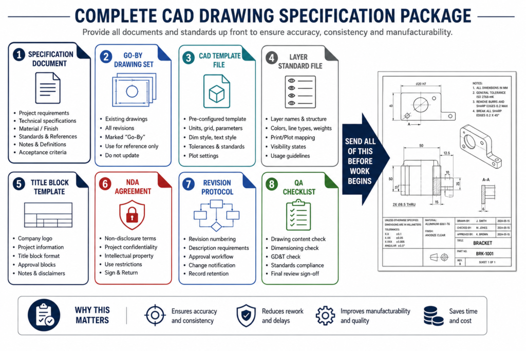
| Quick answer: A CAD drawing specification for outsourcing is a written document defining the drawing standard, CAD software and version, file delivery formats, layer naming, title block requirements, revision protocol, and quality acceptance criteria. Without it, every assumption your partner makes is a potential source of rework. Provide go-by drawings alongside it to communicate style and quality that words alone cannot capture. |
Why a Written Specification Is Not Optional
Every gap in the briefing becomes an assumption. Every assumption your partner makes that differs from your expectation becomes rework. The disciplines that benefit most from documented specifications are also the ones where rework is most expensive: mechanical drawing packages for manufacturing, structural drawing sets for construction, and MEP coordination drawings where errors propagate across multiple trades.
What Happens Without a Specification
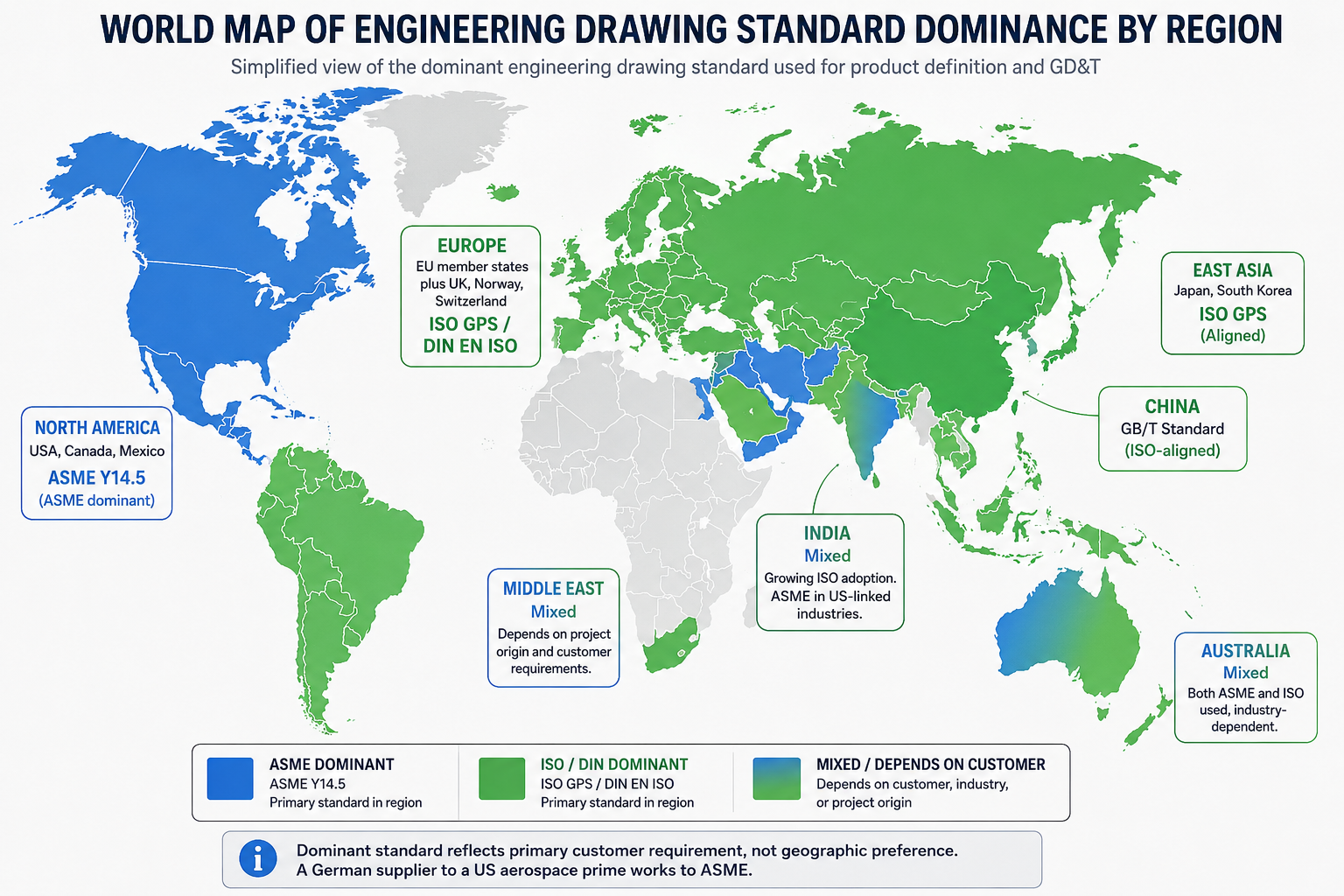
- The partner applies their default drawing standard. If they work to ISO and your manufacturing base works to ASME, the GD&T interpretation is immediately wrong.
- The partner uses their own title block template. Your drawing register uses a specific format. Every drawing must be recreated, not just corrected.
- The partner uses their preferred layer naming convention. New drawings cannot be integrated with your existing archive without a conversion exercise.
- The partner selects the file format they use most. If they deliver DWG 2024 and your CNC software requires DWG 2018, every file must be individually converted.
- The revision protocol is improvised. Mark-ups go by email. Three revisions in, neither party has a reliable audit trail.
Each problem is entirely preventable with a written drawing specification document provided before any work begins.
What Your CAD Drawing Specification Must Contain
A complete CAD drawing specification covers three categories: technical standards governing what the drawing contains, format requirements governing how files are delivered, and process requirements governing how work is managed. Missing any category produces avoidable rework.
| Specification Item | What to State Precisely | Why It Matters If Missing |
| Drawing standard | ASME Y14.5-2018, ISO 1101:2017, or DIN EN ISO equivalent | Partner applies wrong GD&T defaults; form controls misinterpreted |
| CAD software and version | SolidWorks 2025, AutoCAD 2026, Revit 2026, NX 2312 | Incompatible file format or missing features if version differs |
| Deliverable file formats | DWG, STEP, PDF/A, IFC, native format, or combinations | Wrong format blocks downstream workflow with manufacturer or client |
| Sheet size and orientation | ASME A-E or ISO A4-A0, landscape or portrait per sheet | Printed sets misaligned; PDF pagination incorrect for review |
| Title block template | Provide your template file; specify required fields | Partner creates own title block; branding and fields are wrong |
| Layer naming convention | Provide layer standard file or reference document | Layer chaos makes file management and overlay work impossible |
| Line weights and types | Specify or provide a line weight table | Drawings look inconsistent; printed output does not match standard |
| General tolerance standard | ISO 2768-mK or ASME title block tolerance note | Ambiguous tolerances lead to over- or under-constrained parts |
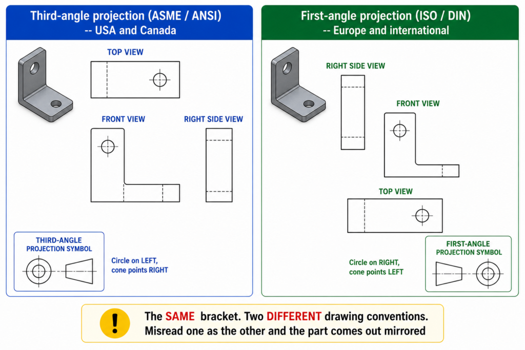
| Projection method | Third-angle (ASME) or first-angle (ISO) | Views misread as mirrored; wrong features on wrong faces |
| Units | Millimetres, inches, or mixed (state clearly) | Dimensional errors from unit conversion if mixed unwittingly |
| Scale convention | 1:1 default; NTS where stated; scale bar required | Printed drawings used for measurement; wrong parts made |
| Revision control system | Revision letter sequence, revision table format, ECN ref | Revision history lost; old revisions used in production |
| Numbering and drawing register | Part number format, drawing number format, BOM numbering | Mismatched part numbers between drawing and procurement |
| BOM format and content | Required columns, hierarchy, link to drawing numbers | BOM does not match drawing; procurement builds wrong assembly |
| Confidentiality level | Proprietary, controlled distribution, or open | Intellectual property risk if unmarked drawings are shared |
The Drawing Standard Declaration
This is the single most technically consequential element. State the standard by name and year: ASME Y14.5-2018, ISO 1101:2017, or DIN EN ISO 2768-mK. If your drawings use multiple standards, state each separately with a clear note about which governs which element.
The Scope Document: Structure That Prevents Disputes
Alongside the technical specification, provide a scope document defining the commercial and process boundaries of the engagement.
| Document Section | What It Must Contain | Common Gap If Missing |
| Project overview | What is being designed, industry context, end use | Partner draws without understanding function; misses safety-critical features |
| Deliverable list | Every drawing type, quantity, and format required | Drawing types or formats missed; argument about scope at invoice |
| Input documents | Go-by drawings, sketches, models, specifications provided | Partner works from memory or assumptions; wrong style or standard |
| Drawing standard reference | Standard name, year, and which elements it governs | Partner applies default standard; GD&T and projections conflict |
| Software requirements | Software name, version, required plugins or templates | File compatibility issues at delivery; cannot open without conversion |
| Timeline and milestones | Submission date per batch, review period, revision deadline | No accountability; delivery slips without contractual reference |
| Revision protocol | How mark-ups are sent, turnaround time, back-redline req | Revision cycles become unstructured; changes get lost or duplicated |
| Quality check requirement | What QA the partner must perform before submission | Unchecked errors submitted; review burden falls entirely on client |
| Communication protocol | Primary contact, escalation path, response time SLA | Communication gaps; decisions made without documentation |
| IP and confidentiality | NDA status, marking requirements, data security standard | Intellectual property risk; no contractual protection if breach occurs |
| Acceptance criteria | What constitutes a complete and acceptable deliverable | Disputes about quality at completion; rework without clear definition |
Go-by Drawings: The Most Effective Tool in Your Specification Package
A specification document tells a partner what you require. Go-by drawings show them. Leading CAD outsourcing providers ask for go-by drawings before beginning any work because a written description of dimension text height 3.5mm with closed filled arrowheads is not as unambiguous as a drawing where the engineer can see exactly what those requirements produce visually.
| Go-by drawing element | What it communicates to your outsourcing partner |
| Title block layout and field positions | Exactly which field goes where, how your company name and logo appear, what the revision table looks like |
| Layer naming and colour assignments | The visual hierarchy of the drawing; what is visible in which colour on screen and in print |
| Line weight hierarchy | Which features print heavy (object lines), medium (hidden), or fine (centre lines, dimension lines) |
| Text height and font | Annotation style throughout: dimension text, note text, title text, table text |
| Dimension style and arrow type | Closed filled arrows vs open arrows; leader line style; tolerance annotation format |
| View layout and spacing | How views are arranged on the sheet; spacing between views; section label placement |
| General notes format and content | Standard notes your drawings carry: projection symbol note, general tolerance note, surface finish default |
| BOM table format | Column headers, row spacing, part number format, quantity and unit format |
| Revision table format | Column headers, revision letter format, description field length, approval field |
| Section and detail view labelling | How section cuts are labelled (A-A, B-B), how detail enlargements are referenced |
| Weld symbol and GD&T callout style | How feature control frames are placed; leader line and flag note conventions |
How to Select Good Go-by Drawings
The best go-by drawings are: technically complete with no missing information, representative of the complexity of work the partner will produce, free of known errors that crept in under schedule pressure, and recently produced to reflect your current standards. Provide at least two to three go-by drawings covering different drawing types and complexity levels.
| Go-by drawing rule: Redact proprietary dimensional information from go-by drawings before sending if they show commercially sensitive products. Replace specific dimensions with representative values while keeping all stylistic and format information intact. The partner needs to see how the drawing is built, not the exact dimensions of the product. |
The Pilot Project: Testing a Partner Before Committing Volume
A pilot project is the most reliable way to discover whether a partner can genuinely meet your specification before you commit significant volume. Every credible outsourcing provider offers pilot work, and many offer it at no charge because they understand it is the normal due diligence step before a production relationship begins.
| Pilot phase | What to include | What you are testing |
| Scope selection | One to three drawings of moderate complexity | Real capability, not a showcase best effort on an easy drawing |
| Full spec provision | Provide your complete specification, templates, and go-by drawings as if for full production | Whether partner can absorb and apply your standards correctly |
| Defined timeline | Set the same turnaround expectation as production; do not give extra time | Real delivery performance, not a padded demonstration |
| Structured review | Review against your specification point by point; document every finding | Whether partner quality matches your requirement, not just your impression |
| Revision round | Issue one complete set of mark-ups; request back-redlined copy with changes highlighted | Revision discipline: how thoroughly and accurately changes are applied |
| Communication log | Note response times, question quality, escalation handling across the pilot period | Whether working relationship will be productive at scale |
| Go/no-go decision | Set explicit criteria before the pilot; do not grade on a curve at the end | Whether this partner can safely receive production work |
Evaluating the Pilot
The pilot review should answer four questions. Did the partner apply your specification correctly without constant reminders? Are the drawings technically complete and accurate, not just visually correct? How did they handle gaps in the specification that required judgment? And was the revision round productive, with changes applied completely and a back-redlined copy returned? The go/no-go decision should be based on objective criteria defined before the pilot begins, not on a general impression.
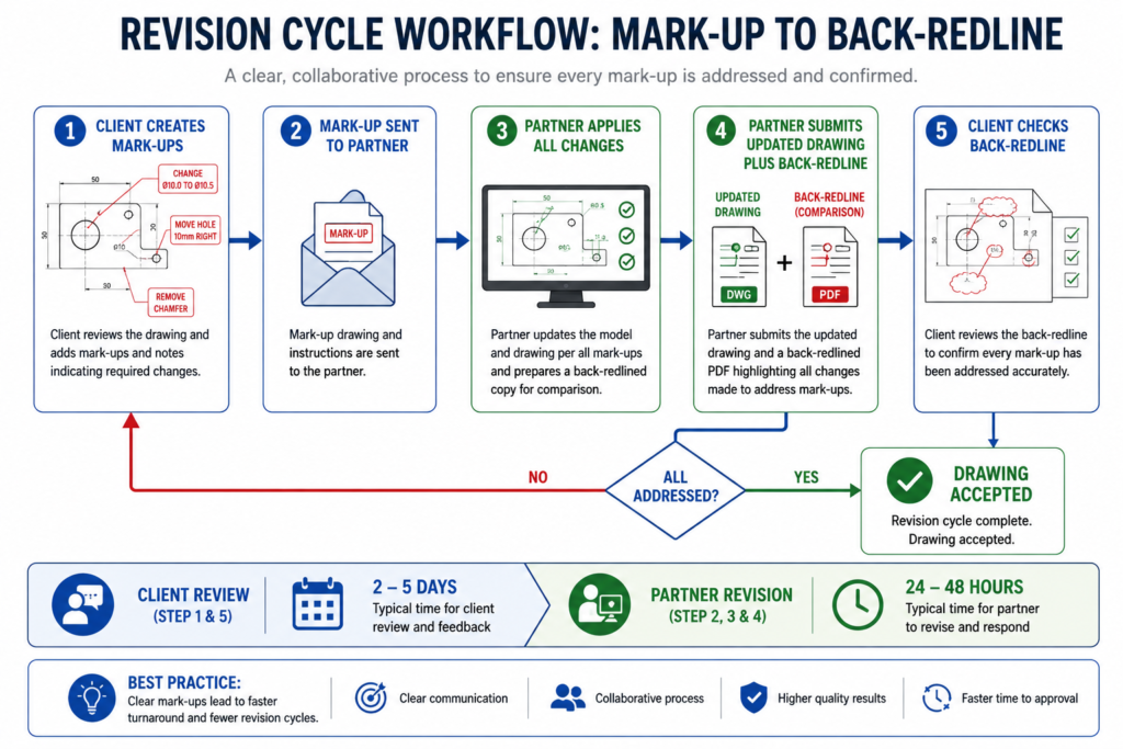
Defining Your Revision Protocol
The revision protocol governs how changes are communicated between your team and the outsourcing partner. Without a documented protocol, mark-up cycles become an email chain where changes get applied partially and both parties lose track of the current revision state.
- Mark-up format: Annotated PDF, redlined DWG, numbered comment list, or cloud review tool. State the format and provide a template.
- Turnaround time: 24 hours, 48 hours, or by a named date. State it explicitly.
- Back-redline requirement: After implementing changes, the partner should return a back-redlined copy showing exactly what changed. This confirms the mark-up was understood and applied completely.
- Revision letter protocol: What triggers a revision letter increment? State it in advance.
- Scope of change vs new drawing: When is a change large enough to become a new drawing? Define the threshold.
| The back-redline rule: Always require a back-redlined copy after every revision round. A partner who returns a clean updated drawing without a back-redline cannot prove every mark-up was addressed. This single practice eliminates the majority of revision disputes. |
Quality Assurance: What to Require Before Submission
Every drawing your outsourcing partner submits should have passed their own internal quality check before it reaches you. Specifying what that check must cover transfers the first-pass review burden to the partner.
| QA check item | What the partner should verify before submission |
| Drawing standard compliance | GD&T symbols, datum notation, and projection method match the stated standard |
| Title block completeness | All mandatory fields populated: drawing number, revision, date, scale, units, approval |
| Layer compliance | All content on correct layers per naming convention; no content on Layer 0 or default layers |
| Revision table accuracy | Revision letter, description, date, and approver fields match the current revision and change log |
| BOM accuracy vs drawing | Every part called out on the drawing appears in the BOM with correct quantity and description |
| Dimension completeness | Every feature required for manufacture is dimensioned; no features defined only by scale |
| Tolerance consistency | No dimension lacks a tolerance where one is required; general tolerance reference in title block |
| View completeness | All referenced views exist on the sheet or a named sheet; all section cuts reference their views |
| File format delivery | All required formats delivered (DWG, PDF, STEP etc.); file naming matches drawing register convention |
| Scale accuracy (model space) | Model drawn at 1:1 in model space; viewports set to specified scales; NTS noted where applicable |
| Spell check and nomenclature | Notes, labels, and BOM descriptions spell-checked; terminology consistent with client standards |
Intellectual Property and Data Security
When you outsource CAD drawings, you share information about your products, designs, and clients with a third party. That information needs legal and procedural protection before it is shared, not after a breach has occurred.
The NDA: Sign Before You Brief
A Non-Disclosure Agreement should be signed before any project information is shared, including during scope discussions and before providing go-by drawings. Make it a standing rule: NDA first, then specification, then go-by drawings, then project briefing.
Drawing Confidentiality Markings
Every drawing sheet should carry a confidentiality marking: PROPRIETARY, CONFIDENTIAL, or CONTROLLED DISTRIBUTION. Specify the required markings in your drawing specification and provide a template that includes them in the correct title block position.
Data Security Requirements
- File storage: State where project files must be stored. Prohibit storage on personal devices or consumer file-sharing services.
- Access control: Who within the partner organisation may access the files?
- Subcontracting: Is the partner permitted to pass work to subcontractors? Under what conditions?
- File deletion: When and how are your files deleted at project end? Request written confirmation.
- Software licensing: Confirm the partner uses fully licensed CAD software.
| The most common IP mistake in CAD outsourcing: Providing go-by drawings and project sketches before the NDA is signed because the partner needs to see the scope to quote it. A responsible partner will sign the NDA before receiving any design information. If a prospective partner resists signing before the briefing, that is itself a red flag about their approach to client data. |
Managing the Outsourcing Relationship After It Starts
Single Point of Contact
Nominate one internal contact for all communication with the outsourcing partner. When multiple team members brief the partner independently, the partner receives conflicting instructions. The resulting drawings satisfy one internal stakeholder and disappoint another.
Regular Output Review
Do not wait for a large batch to be complete before reviewing quality. Schedule periodic light reviews of recent submissions against your specification. Drift happens gradually: a partner fully compliant at pilot end may begin taking shortcuts on elements rarely checked.
Specification Version Control
Treat the drawing specification exactly as you would treat an engineering drawing: version-control it, note what changed in each revision, and confirm the partner has received and understood the updated version before they produce work to it.
10 CAD Outsourcing Briefing Failures That Produce Rework
These are the patterns that appear most consistently when outsourced drawing quality falls short. Almost all trace back to something not specified at the start rather than any failure of partner capability.
| Failure | What happens | How to prevent it |
| Spec given verbally or by email thread | Partner interprets differently; no audit trail | Always deliver a written specification document, not a call summary. Version control it. |
| No go-by drawings provided | Partner creates own style; training rework needed | Provide go-by drawings before work starts. Allow no assumptions about style. |
| Drawing standard not stated | Partner applies their default; GD&T misinterpreted | State the standard explicitly. ASME Y14.5-2018 or ISO 1101:2017. |
| Software version not specified | File delivered in incompatible format or version | Name the exact software and version. Include required plugins or template files. |
| No pilot project run | Misalignment discovered after full batch submitted | Always run a scoped pilot before committing full production volume to a new partner. |
| Revision protocol undefined | Mark-ups lost; changes applied inconsistently | Define revision turnaround, back-redline requirement, and mark-up format before work begins. |
| NDA not signed before briefing | IP disclosed before legal protection is in place | Execute NDA before any project information is shared, including during scope discussion. |
| No acceptance criteria defined | Disputes about what correct means at delivery | Define acceptance criteria in the specification before work starts, not during review. |
| Single point of contact not defined | Multiple people brief partner inconsistently | Nominate one internal contact for all communication. Document this in the spec. |
| No versioning on specification itself | Spec updated informally; partner works to old version | Version-control your specification document. Treat it like an engineering drawing. |
| The outsourcing briefing checklist: Before assigning any work: (1) NDA signed. (2) Written specification provided and version-controlled. (3) Go-by drawings provided for all drawing types. (4) CAD template and layer standard files provided. (5) Pilot project scoped, run, and evaluated against objective criteria. (6) Revision protocol agreed. (7) QA checklist provided. (8) Single point of contact confirmed on both sides. (9) File format and software version confirmed compatible. (10) IP and data security requirements stated in writing. Ten items. All preventable rework if addressed before work begins. |
AI and Digital Collaboration Tools in CAD Outsourcing in 2026
Cloud-based review platforms like Bluebeam Revu and Autodesk Construction Cloud allow mark-ups in a shared environment with every comment timestamped and tracked. AI-assisted review tools like CoLab AutoReview automate first-pass checks of submitted drawings against company standards. AI tools like Claude can draft a complete CAD drawing specification from a conversational description of requirements, reducing the time from ‘we need a spec’ to ‘the partner has it’ from days to hours.
Conclusion:
The quality of your CAD outsourcing relationship is determined before the first drawing is produced. It is determined by the completeness of the specification you provide, the relevance of the go-by drawings you include, the rigour of the pilot project you run, and the clarity of the protocols you define for revision, QA, and communication.
Outsourcing partners in 2026 are generally capable. What they cannot invest in is your specific drawing standard, your specific title block, your specific revision convention, and your specific layer naming. That knowledge lives in your organisation and must travel to them in writing.
A good specification is the contract between what you need and what you receive. Write it that way.
Frequently Asked Questions
What is a CAD drawing specification for outsourcing?
A CAD drawing specification for outsourcing is a written document defining every technical, format, and process requirement your external CAD partner must meet. It covers the drawing standard, CAD software and version, file delivery formats, layer naming, title block requirements, general tolerance reference, revision control protocol, and quality acceptance criteria. Without it, every assumption your partner makes is a potential source of rework.
What are go-by drawings in CAD outsourcing?
Go-by drawings are representative examples from your existing drawing set provided to a partner as a visual reference for style, standard, and quality expected. They communicate what a written specification cannot: layer structure, line weights, text heights, dimension style, title block layout, and BOM format. A good go-by set covers a range of drawing types representative of the work the partner will produce.
How do you run a pilot project with a new CAD outsourcing partner?
A pilot project involves issuing one to three representative drawings to a new partner before committing full volume. Provide the complete specification, templates, and go-by drawings. Set the same timeline as production. Review output against your specification point by point. Issue one revision round and check whether all changes are applied correctly with a back-redlined copy returned. Define go/no-go criteria before the pilot begins.
What file formats should I specify for CAD drawing outsourcing?
File format for CAD drawing requirements depend on your downstream workflow. For manufacturing: DWG and PDF/A. For BIM coordination: Revit native plus IFC. For machining: STEP alongside 2D DWG. For sheet metal: DXF for flat patterns. Always specify the software version alongside the format because DWG from AutoCAD 2026 may not open correctly in AutoCAD 2019 without conversion.
How do I protect my IP when outsourcing CAD drawings?
IP protection requires three measures. First, a signed NDA before any project information is shared. Second, confidentiality markings on every drawing sheet. Third, data security requirements in the specification covering file storage location, access control, subcontracting restrictions, and file deletion procedures at project end.
What should a CAD drawing outsourcing scope document contain?
A scope document should contain: a project overview, a complete deliverable list, a list of input documents provided, the applicable drawing standard, software and version requirements, a timeline with milestones, the revision protocol, QA requirements the partner must perform before submission, communication protocols, IP and confidentiality requirements, and acceptance criteria defining what constitutes a complete and acceptable deliverable.
‘ASME Y14.100: the engineering drawing practices standard governing drawing completeness and approval’