Every structure that stands, every machine that moves, and every vehicle that travels owes its safe and predictable behaviour to one foundational discipline: engineering mechanics. It is the scientific backbone of engineering, the toolkit that allows engineers to move from “I think this will hold” to “I can prove this will hold, here is the calculation.”
And yet, for many engineering students encountering it for the first time, engineering mechanics can feel abstract, disconnected from the real world, or simply overwhelming. A subject full of vectors, free body diagrams, Newton’s laws, and equilibrium equations does not always arrive with a clear sense of why it matters or how it connects to the things engineers actually build.
This guide fixes that. It explains engineering mechanics from the ground up: what it is, how it is structured, what each branch covers, how its principles are applied in practice, which tools engineers use to apply them, and how mastery of the subject translates into a professional engineering career. Whether you are a first-year student facing your first mechanics module, a professional refreshing your foundations, or simply someone who wants to understand the science behind the built world, this is the most complete and readable explanation you will find.
| Quick Answer: Engineering mechanics is the branch of applied science that uses the principles of physics and mathematics to predict and analyse how physical bodies respond to forces, motion, and deformation. It is the foundational discipline of virtually all engineering fields and is divided into three primary branches: statics (bodies in equilibrium), dynamics (bodies in motion), and mechanics of materials (how materials deform and fail under load). |
What Is Engineering Mechanics? A Clear Definition
Engineering mechanics is the application of the principles of classical mechanics, a branch of physics, to solve practical engineering problems. It deals with the behaviour of physical bodies when subjected to forces or displacements, and the subsequent effects those forces and displacements have on the bodies and their surrounding environments.
The word “engineering” in engineering mechanics is important. Pure or theoretical mechanics asks: “What happens?” Engineering mechanics asks: “What happens, and how do we use that knowledge to design something safe, efficient, and reliable?” The distinction is the difference between scientific knowledge and the professional application of that knowledge.
At its core, engineering mechanics is concerned with three fundamental physical quantities: force, motion, and deformation. Every problem in engineering mechanics ultimately reduces to understanding how these three quantities interact in a specific physical situation.
| Simple Everyday Example: When you sit on a chair, engineering mechanics explains why the legs do not buckle (statics), why the chair does not vibrate excessively when you move (dynamics), and why the material of the chair deforms slightly but springs back when you stand up (mechanics of materials). All three branches of engineering mechanics are at work simultaneously in that single, unremarkable act. |
The Full Map of Engineering Mechanics: How It Is Structured
Most introductory resources present engineering mechanics as simply “statics and dynamics”. That is a significant oversimplification. The full discipline is structured as a hierarchy of sub-fields, each building on the one before it.
| Level | Sub-Field | What It Studies | Prerequisite |
| Foundation | Classical Mechanics | The general science of motion, force, and matter: Newton’s Laws, conservation of momentum, energy | Mathematics (vectors, calculus, differential equations) |
| Primary Branch 1 | Rigid Body Mechanics | Bodies that do not deform under load: all statics and most dynamics problems | Classical mechanics |
| Sub-branch 1a | Statics | Forces on bodies in equilibrium (at rest or constant velocity) | Rigid body mechanics |
| Sub-branch 1b | Dynamics: Kinematics | Description of motion (displacement, velocity, acceleration) without reference to force | Statics |
| Sub-branch 1c | Dynamics: Kinetics | Forces that cause or result from motion; Newton’s 2nd Law applied to moving bodies | Kinematics |
| Sub-branch 1d | Vibrations | Oscillatory motion in mechanical systems; forced and free vibrations, resonance | Kinetics |
| Primary Branch 2 | Deformable Body Mechanics (Mechanics of Materials) | How real materials stretch, compress, bend, and fail under load | Statics |
| Sub-branch 2a | Stress and Strain Analysis | Internal force distribution and deformation in loaded bodies | Mechanics of materials |
| Sub-branch 2b | Fracture and Fatigue Mechanics | Crack propagation, fatigue life prediction, failure analysis | Stress and strain analysis |
| Sub-branch 2c | Continuum Mechanics | Generalised treatment of both solid and fluid deformation under load | Advanced mathematics |
| Primary Branch 3 | Fluid Mechanics | How liquids and gases respond to forces; pressure, flow, viscosity, turbulence | Classical mechanics |
| Sub-branch 3a | Hydrostatics | Fluids at rest: pressure distribution, buoyancy, forces on submerged surfaces | Fluid mechanics |
| Sub-branch 3b | Hydrodynamics / CFD | Fluids in motion: Bernoulli’s equation, pipe flow, aerodynamics, turbulence | Hydrostatics |
This hierarchy matters because it explains the logical order in which engineering mechanics is taught. You cannot understand dynamics without statics. You cannot understand mechanics of materials without statics. You cannot understand vibrations without dynamics. The subject is hierarchical by nature, which is why first-year engineering students universally encounter statics before any other engineering mechanics topic.
Why Engineering Mechanics Is Taught First
Almost every accredited engineering degree in the world, regardless of whether it is mechanical, civil, aerospace, structural, chemical, or industrial, includes engineering mechanics in its first or second semester. This is not a coincidence or an academic tradition preserved from habit. There are precise and compelling reasons why engineering mechanics occupies this foundational position.
It Is the Language of Engineering Analysis
Engineering mechanics provides the conceptual vocabulary and analytical framework that every other engineering subject uses. Structural analysis uses statics. Machine design uses dynamics and mechanics of materials. Thermodynamics uses concepts of force and energy from mechanics. Fluid mechanics is itself a branch of engineering mechanics. Without a solid foundation in engineering mechanics principles, none of the more advanced engineering subjects can be properly understood.
It Develops the Problem-Solving Mindset Engineering Requires
Engineering mechanics is one of the most rigorous training grounds for the analytical problem-solving approach that all engineering practice demands. The discipline requires students to extract the physically relevant information from a real-world situation, draw a free body diagram, write the governing equations, solve for unknowns, check the result for physical plausibility, and present a clear, defensible answer. This disciplined problem-solving loop is the method all engineers use, regardless of their specialism.
It Instils the Habit of Quantification
A core engineering habit is that gut feelings and intuitions must always be tested against numbers. Engineering mechanics is where engineers first learn to be quantitative about the physical world: to ask not just “will this beam bend?” but “by how much will it deflect under this load, and is that deflection within the allowable limit?” This habit of quantification is what distinguishes professional engineering from guesswork.
| Historical Context: The formalisation of engineering mechanics as a taught discipline dates to the 18th century and the work of mathematicians and physicists including Leonhard Euler, Joseph-Louis Lagrange, and later Augustin-Louis Cauchy. Euler’s equations of motion for rigid bodies, Lagrange’s analytical mechanics, and Cauchy’s stress tensor are all contributions that still appear, in simplified form, in first-year engineering mechanics textbooks today. |
Newton’s Laws of Motion: The Engine of Engineering Mechanics
The entire edifice of engineering mechanics rests on three laws formulated by Sir Isaac Newton in 1687. Understanding these laws at the level of a working engineer, not just a physics student, is the single most important conceptual foundation in the discipline.
Newton’s First Law: The Law of Inertia
A body remains at rest, or continues to move in a straight line at constant velocity, unless acted upon by a net external force.
Engineering application: This law is the conceptual foundation of statics. If a structure is at rest, the net force and net moment acting on it must both equal zero. That is the condition of static equilibrium, and it is the governing principle for every static analysis in structural and mechanical engineering. It is also why a satellite in orbit does not need continuous thrust to stay in motion: there is no net force opposing it in the vacuum of space.
Newton’s Second Law: The Law of Acceleration
The net force acting on a body is equal to the product of its mass and its acceleration: F = ma.
Engineering application: This is the governing equation of kinetics, the branch of dynamics that deals with forces and motion. It is used to calculate the braking distance of a vehicle, the thrust required to accelerate a rocket, the force on a connecting rod in a reciprocating engine, and the loads transmitted through a vehicle suspension system during a pothole impact. It is perhaps the single most applied equation in all of mechanical engineering.
Newton’s Third Law: The Law of Action and Reaction
For every action there is an equal and opposite reaction.
Engineering application: This law explains why a rocket accelerates in one direction by expelling mass in the other. It explains why a beam exerts an upward reaction force on a support equal to the downward load the beam carries. It is why the analysis of forces in any connected system must account for reaction forces at every joint, support, and contact point. In structural analysis, identifying and correctly calculating reaction forces is one of the most fundamental skills a student of engineering mechanics must develop.
| Newton’s Law | Statement | Primary Mechanics Branch | Key Engineering Applications |
| First Law (Inertia) | A body at rest or constant velocity has zero net force | Statics | Structural support design, bridge analysis, building load calculations, static equilibrium of machines |
| Second Law (F = ma) | Net force equals mass times acceleration | Dynamics (Kinetics) | Vehicle braking, engine load analysis, rocket propulsion, crash mechanics, earthquake response |
| Third Law (Action-Reaction) | Every force has an equal and opposite reaction force | Statics and Dynamics | Reaction forces at supports, joint loads in trusses, thrust and propulsion, ground contact forces |
Branch 1: Statics Explained in Full
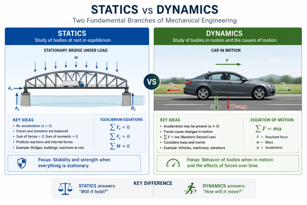
Statics is the branch of engineering mechanics that studies the behaviour of bodies under forces that produce a state of equilibrium: a condition where there is no net force and no net moment (turning effect) acting on the body. In simple terms, statics is the study of things that are not accelerating.
The name “statics” can be misleading. A body does not need to be literally stationary to be in static equilibrium. A car travelling at constant velocity on a straight road is in dynamic equilibrium: the driving force exactly balances the drag and rolling resistance, producing zero net force and zero acceleration. Statics applies to both these situations.
The Two Conditions of Static Equilibrium
For any body to be in static equilibrium, two conditions must be simultaneously satisfied:
- The sum of all forces acting on the body must equal zero (translational equilibrium: the body does not accelerate in any direction).
- The sum of all moments (torques) acting on the body must equal zero (rotational equilibrium: the body does not rotate).
In two-dimensional problems (the vast majority of introductory statics), this produces three scalar equations: the sum of forces in the x-direction equals zero, the sum of forces in the y-direction equals zero, and the sum of moments about any chosen point equals zero. These three equations can be used to solve for up to three unknown forces or reactions.
Core Concepts in Statics
Force vectors and resultants: All forces are vectors: they have both magnitude and direction. When multiple forces act on a body, they can be combined into a single resultant force using vector addition.
Moments and torques: A moment is the turning effect of a force about a point. It is calculated as the product of the force magnitude and the perpendicular distance from the line of action of the force to the point (the moment arm). Moments are responsible for bending in beams and rotation in mechanisms.
Support reactions: Real structures are supported in ways that prevent certain types of motion. A pin support prevents translation but allows rotation. A fixed support prevents both translation and rotation. Engineering mechanics provides the tools to calculate the reaction forces and moments at these supports.
Trusses and frames: A truss is a structure made of straight members connected at joints, designed to carry loads efficiently. The method of joints and the method of sections are standard techniques in statics for determining the forces in individual truss members.
Friction: Coulomb friction is the tangential resistance force between surfaces in contact. Statics includes the analysis of systems where friction plays a role, such as wedges, screws, belt drives, and braking systems.
Real-World Applications of Statics
| Application | How Statics Is Used |
| Bridge design | Calculating support reactions, member forces in trusses, and stability under traffic loads |
| Building structural analysis | Ensuring floors, beams, and columns can safely carry occupancy and wind loads without collapsing |
| Crane and lifting equipment | Determining the stability of lifting arms and calculating loads on cables and pulleys |
| Bolt and fastener design | Calculating the shear and tensile loads on fasteners in mechanical assemblies |
| Ergonomic tool design | Analysing the forces and moments at the hand and wrist to minimise repetitive strain risk |
| Dam wall design | Calculating the hydrostatic pressure distribution and overturning moment from retained water |
Branch 2: Dynamics Explained in Full
Dynamics is the branch of engineering mechanics that deals with bodies in motion, and specifically with cases where the motion involves acceleration. While statics describes equilibrium, dynamics describes change: changing velocity, changing direction, and the forces responsible for those changes.
Dynamics is divided into two distinct sub-areas that are often studied sequentially: kinematics and kinetics. Understanding the distinction between these two is one of the first conceptual milestones in any dynamics course.
Kinematics: Describing Motion Without Forces
Kinematics is the purely geometric description of motion. It deals with how position, velocity, and acceleration relate to each other and to time, without asking what forces caused the motion. A kinematic analysis of a car journey calculates displacement, speed, and acceleration purely from the geometry of the motion.
Key kinematic quantities include: displacement (change in position), velocity (rate of change of displacement), acceleration (rate of change of velocity), and angular equivalents of each for rotating bodies. Kinematics is particularly important in the design of mechanisms: gear trains, cam-follower systems, linkages, and robotic arms, where the designer needs to understand the motion geometry before analysing the forces.
Kinetics: Relating Forces to Motion
Kinetics applies Newton’s Second Law (F = ma) to relate the forces acting on a body to its resulting acceleration. Where kinematics asks “how does the body move?”, kinetics asks “why does the body move that way, and what force is required to produce that motion?”
Kinetics methods include Newton-Euler direct application (summing forces and moments), work-energy methods (relating force and displacement to changes in kinetic energy), and impulse-momentum methods (relating force and time to changes in momentum). Each method has situations where it is particularly efficient, and a skilled engineer chooses the most appropriate method for each problem.
Vibrations: The Dynamic Behaviour of Elastic Systems
Vibrations is a sub-discipline of dynamics that studies oscillatory motion. Almost every mechanical system vibrates to some degree when disturbed, and understanding and controlling those vibrations is critically important in engineering. Excessive vibration causes fatigue failure, noise, discomfort, and loss of precision.
Key concepts in vibration analysis include natural frequency (the frequency at which a system naturally oscillates when disturbed), resonance (the catastrophic amplification of vibration that occurs when an excitation frequency matches the natural frequency), damping (energy dissipation that reduces vibration amplitude), and forced vibration (oscillation driven by a sustained external force).
| Famous Engineering Failure: Resonance in Action: The Tacoma Narrows Bridge collapsed in 1940 because wind-induced oscillations matched the bridge’s natural frequency, causing resonance. The amplitude of vibration grew until the structure tore itself apart. This disaster fundamentally changed how engineers account for dynamic loads and aerodynamic effects in bridge design, and it remains the most cited example of resonance failure in engineering education worldwide. |
Real-World Applications of Dynamics
| Application | How Dynamics Is Used |
| Automotive engineering | Crash analysis, suspension dynamics, engine vibration, drivetrain load calculation, ABS braking system design |
| Aerospace engineering | Flight dynamics, landing gear impact loads, aeroelastic analysis, satellite orbit mechanics, launch vehicle trajectory |
| Robotics | Joint torque calculations, trajectory planning, dynamic stability of walking robots, end-effector force control |
| Rotating machinery | Balancing of rotating components, shaft critical speeds, bearing load analysis in turbines and motors |
| Earthquake engineering | Dynamic response of structures to ground motion; resonance avoidance in building and bridge design |
| Sports engineering | Biomechanical analysis of athletic motion; equipment dynamics in golf clubs, tennis rackets, bicycle frames |
Branch 3: Mechanics of Materials (Strength of Materials) Explained
Statics and dynamics treat bodies as rigid: they analyse forces and motion without considering how the material of a body deforms under those forces. Mechanics of materials (also called strength of materials) removes that simplification and asks: given the forces a component must carry, how does the material actually deform, and will it survive?
This branch of engineering mechanics bridges the gap between theoretical statics and practical design. Knowing the forces on a beam from a statics analysis is only the first step. The second step, which mechanics of materials provides, is determining whether a given material and cross-sectional shape can carry those forces without yielding, fracturing, or deflecting beyond acceptable limits.
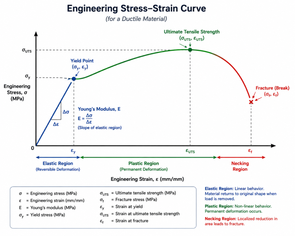
Stress and Strain: The Language of Material Behaviour
Stress is the internal force per unit area within a material, measured in Pascals (Pa) or pounds per square inch (psi). It represents how intensely a material is being loaded at any given point. Strain is the ratio of deformation to original dimension: a dimensionless measure of how much the material has changed shape relative to its unloaded state.
The relationship between stress and strain is described by a material’s stress-strain curve. In the elastic region (below the yield strength), stress and strain are proportional, described by Hooke’s Law: stress = E x strain, where E is the Young’s modulus of elasticity, a material property describing stiffness. Beyond the yield point, permanent (plastic) deformation occurs.
Types of Stress in Engineering Components
- Axial (normal) stress: Stress acting perpendicular to a cross-section, caused by tensile or compressive forces along a member’s axis. Applicable to columns, tie rods, and fasteners.
- Shear stress: Stress acting parallel to a cross-section, caused by forces that tend to cause sliding failure. Critical in bolts, welds, and shaft keyways.
- Bending stress: Stress distribution across the cross-section of a beam due to a bending moment. Maximum at the outer fibres, zero at the neutral axis. Governs the design of most structural beams and shafts.
- Torsional stress: Stress caused by twisting moments (torques) applied to shafts. Critical in drive shafts, bolts, and any rotating component.
- Combined loading: Most real components experience several stress types simultaneously. Combined loading analysis and failure criteria such as Von Mises and Tresca determine whether a component will survive the combined stress state.
Buckling: The Failure Mode Unique to Compression
Buckling is a sudden failure mode that can occur in slender compression members (columns) well below the material’s yield stress. It is a stability failure, not a strength failure: the column becomes geometrically unstable and bends sideways catastrophically. Euler’s buckling formula gives the critical compressive load above which a column will buckle, and it is one of the most important results in structural engineering.
Branch 4: Fluid Mechanics as Part of Engineering Mechanics
Fluid mechanics is the branch of engineering mechanics that studies the behaviour of fluids (liquids and gases) under the action of forces. It is sometimes treated as a standalone discipline, but it is deeply rooted in the same physical principles (Newton’s laws, conservation of energy, conservation of mass) that govern solid mechanics.
Engineers encounter fluid mechanics problems in an enormous range of contexts: the flow of water through pipes in a building, the aerodynamics of a vehicle body, the lubrication of a bearing, the cooling of a computer chip, the thrust generated by a jet engine, and the pressure distribution on a dam wall. Without a working understanding of fluid mechanics principles, mechanical and civil engineers could not design any of these systems.
Hydrostatics vs. Hydrodynamics
Hydrostatics deals with fluids at rest. Its primary concerns are pressure distribution in stationary fluids, buoyancy forces on submerged objects (described by Archimedes’ principle), and forces on submerged surfaces such as dam walls and tank floors.
Hydrodynamics (fluid dynamics) deals with fluids in motion. It analyses how velocity, pressure, and density change through a flowing fluid system. Bernoulli’s equation is the most famous result of fluid dynamics, relating fluid speed, pressure, and elevation in an ideal (frictionless, incompressible) flow. Real flows involve viscosity and turbulence, requiring the full Navier-Stokes equations, which can generally only be solved numerically using Computational Fluid Dynamics (CFD) software.
Branch 5: Continuum Mechanics and Advanced Applications
Continuum mechanics is the generalised mathematical framework that treats both solid and fluid mechanics within a single unified theory. It assumes that matter is continuously distributed throughout a body (as opposed to treating materials as collections of discrete atoms), and it uses tensor mathematics to describe stress, strain, and deformation in three dimensions.
Continuum mechanics provides the theoretical foundation for advanced finite element analysis, computational fluid dynamics, and the analysis of complex materials such as polymers, biological tissues, and composite materials that do not behave in the simple linear-elastic manner assumed by introductory mechanics of materials.
While continuum mechanics is an advanced topic typically encountered at postgraduate level, its practical consequences appear in everyday engineering tools. When a mechanical engineer uses ANSYS or Abaqus to run a finite element analysis on a complex 3D part, the mathematical engine underneath that simulation is built on continuum mechanics principles.
Free Body Diagrams: The Most Important Tool in Engineering Mechanics
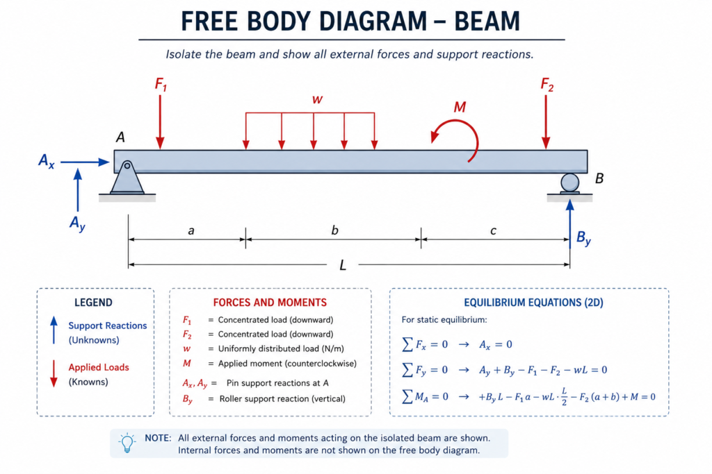
If there is one practical skill that is absolutely central to engineering mechanics, it is the ability to draw an accurate free body diagram (FBD). An FBD is a simplified sketch of a body or system, isolated from its surroundings, showing all the external forces and moments acting on it. It is the engineer’s method of translating a complex physical situation into a tractable mathematical problem.
How to Draw a Free Body Diagram: Step by Step
- Identify the body of interest: Decide clearly which object or system you are analysing. Draw it in isolation, separated from everything it contacts.
- Identify all external forces: Include applied loads (weights, pressures, applied forces), support reactions (from pins, rollers, fixed supports), and contact forces (friction, normal contact forces at surfaces).
- Represent each force as a vector: Show the direction, line of action, and point of application of each force. Label each force with a symbol (F1, W, R_A, etc.).
- Establish a coordinate system: Choose x and y axes (and z for 3D problems) to resolve forces into components.
- Write the equilibrium equations: For statics, set sum of forces and sum of moments equal to zero. For dynamics, set sum of forces equal to ma (Newton’s Second Law).
- Solve for unknowns: Use the equations to calculate unknown forces, reactions, or accelerations.
| Pro Tip: The quality of a free body diagram determines the quality of the subsequent analysis. An incomplete or incorrectly drawn FBD will produce wrong answers even with perfect mathematics. Experienced engineers draw FBDs carefully, checking that every contact surface, every support, and every applied load is accounted for before writing a single equation. This habit, developed in engineering mechanics courses, is one of the most transferable analytical skills in the entire engineering curriculum. |
Engineering Mechanics vs. Theoretical Mechanics: What Is the Difference?
A question that occasionally arises is: how does engineering mechanics differ from theoretical or classical mechanics as studied by physicists?
| Aspect | Engineering Mechanics | Theoretical / Classical Mechanics |
| Primary Goal | Provide tools to design and analyse safe, functional engineering systems | Understand the fundamental laws governing physical reality |
| Mathematical Depth | Applied mathematics: vectors, basic calculus, differential equations | Advanced mathematics: Hamiltonian mechanics, Lagrangian mechanics, tensor calculus |
| Approach to Problems | Idealised models designed to be tractable and practically useful | Generalised, abstract formulations applicable to all physical systems |
| Treatment of Constraints | Practical support conditions, friction, and contact modelled pragmatically | Holonomic and non-holonomic constraints treated with full generality |
| Output | Forces, stresses, deflections, accelerations: numbers that inform design decisions | Equations of motion, conservation laws, symmetry principles: fundamental understanding |
| Who Studies It | All engineering students; foundation of engineering practice | Physics students, applied mathematicians, research engineers at advanced level |
Engineering Mechanics vs. Mechanical Engineering: Understanding the Distinction
These two terms are frequently confused, even by people within the engineering profession. The distinction is clear and important.
Engineering mechanics is a subject or scientific discipline: a specific body of knowledge about forces, motion, and deformation. It is a foundational subject studied across many engineering programs.
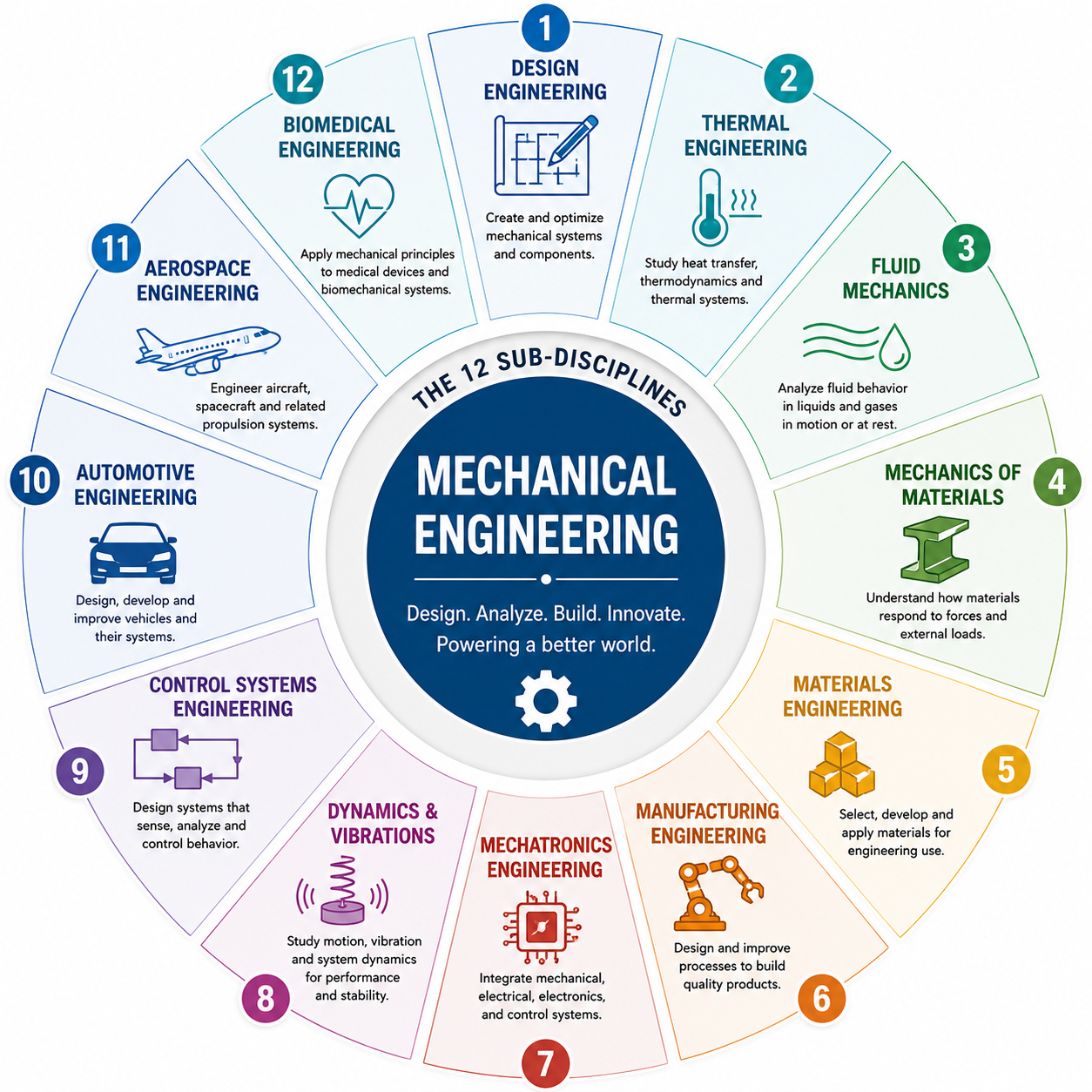
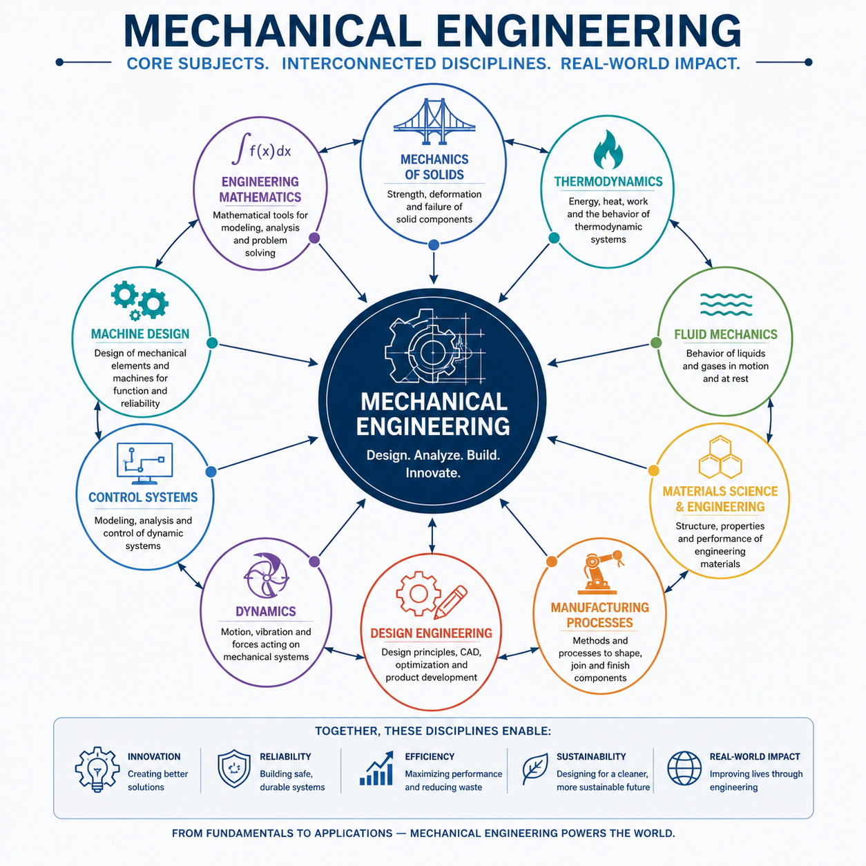
Mechanical engineering is a professional field and degree program: a comprehensive engineering discipline that uses engineering mechanics as one of its foundational tools, alongside thermodynamics, fluid mechanics, manufacturing, materials science, design, and control systems.
The analogy: engineering mechanics is to mechanical engineering what grammar is to literature. You cannot write well without knowing grammar, but knowing grammar does not make you a novelist. Engineering mechanics is the grammatical foundation; mechanical engineering is the full creative and professional practice built on that foundation.
| Aspect | Engineering Mechanics | Mechanical Engineering |
| What it is | A foundational scientific discipline: the study of forces, motion, and deformation | A professional engineering field: broad application of science to design, build, and maintain mechanical systems |
| Scope | Focused: mechanics of rigid bodies, deformable bodies, and fluids | Broad: encompasses EM plus thermodynamics, design, manufacturing, controls, materials science |
| Studied by | Students across all engineering disciplines in first/second year | Mechanical engineering students specifically, plus relevant electives in related programs |
| Output | Analytical results: forces, stresses, deflections, motions | Engineering products: machines, systems, devices, processes |
| Relationship | Engineering mechanics is a foundational component of mechanical engineering | Mechanical engineering is the broader discipline that applies EM and many other tools |
How Engineering Mechanics Is Applied Across Industries
The principles of engineering mechanics are applied in some form in virtually every industry that involves physical systems. The following examples illustrate how specific concepts from the discipline translate into real engineering work.
| Industry | Engineering Mechanics Concepts Applied | Specific Example |
| Automotive | Statics (load paths), dynamics (crash analysis, NVH), mechanics of materials (fatigue), fluid mechanics (aerodynamics) | FEA crash simulation to meet Euro NCAP safety ratings; suspension kinematics design for handling performance |
| Aerospace | Structural statics, flight dynamics, aeroelasticity, fracture mechanics, fluid mechanics (CFD) | Wing spar stress analysis; flutter analysis to prevent resonance-induced structural failure in flight |
| Civil / Structural | Statics (truss and frame analysis), dynamics (seismic response), mechanics of materials (beam design) | Design of a reinforced concrete floor slab to carry specified occupancy loads with controlled deflection |
| Energy (Oil, Gas, Renewables) | Statics (pipe stress), dynamics (vibration of pipelines and turbines), fluid mechanics (pipe flow) | Wind turbine blade structural optimisation; offshore pipeline fatigue life assessment |
| Robotics and Automation | Kinematics (path planning), kinetics (joint torque), statics (payload capacity) | Calculation of motor torques required at each joint of a robotic arm to lift a specified load |
| Biomedical / Medical Devices | Statics and mechanics of materials (implant load bearing), biomechanics (human joint forces) | Hip replacement implant design: ensuring the prosthesis can survive 30 years of walking loads without fatigue fracture |
| Manufacturing | Statics (fixture design), dynamics (machine tool vibration), mechanics of materials (forming operations) | Press tool design: calculating die forces and spring-back in sheet metal forming; avoiding chatter in CNC machining |
| Consumer Products | Statics and mechanics of materials (structural adequacy), dynamics (drop test simulation) | Laptop chassis design: ensuring structural integrity under drop impact and sustained keyboard typing loads |
Modern Tools Used to Apply Engineering Mechanics
While the principles of engineering mechanics are centuries old, the tools that engineers use to apply those principles have been transformed by computing. Modern engineering practice relies on a combination of hand analysis (for checking, scoping, and understanding) and powerful software tools (for high-fidelity analysis of complex systems).
Finite Element Analysis (FEA) Software
FEA software such as ANSYS, Abaqus, and SolidWorks Simulation numerically solves the governing equations of solid mechanics across complex 3D geometries by dividing them into thousands of small elements. FEA allows engineers to determine stress distributions, deflections, natural frequencies, and buckling loads in components too geometrically complex for analytical hand calculation. Proficiency in at least one FEA package is an expected skill for most structural, mechanical, and aerospace engineering roles.
Computational Fluid Dynamics (CFD) Software
CFD tools such as ANSYS Fluent, OpenFOAM, and STAR-CCM+ solve the Navier-Stokes equations numerically across complex fluid domains. They enable engineers to analyse airflow around vehicle bodies, thermal management in electronics, combustion in engines, and pressure drops in pipe networks, without physical wind tunnels or flow experiments in many cases.
Multi-Body Dynamics (MBD) Software
Multi-body dynamics tools such as Adams (MSC Software) and SIMPACK simulate the kinematic and dynamic behaviour of mechanical systems with multiple interconnected rigid or flexible bodies. They are used extensively in automotive suspension analysis, robotic mechanism design, and machinery simulation.
Mathematical and Programming Tools
MATLAB remains the dominant tool for engineering calculation, data analysis, and numerical simulation in academic and industrial settings. Python is increasingly used for engineering calculation scripting, particularly in research and simulation automation. Both are tools that any modern engineer working in analysis and simulation should be proficient with.
Industry Trend: The integration of AI and machine learning into engineering simulation workflows is accelerating. Physics-informed neural networks (PINNs), for example, use machine learning to solve partial differential equations at speeds that traditional FEA cannot match. Mechanical engineers who understand both the classical mechanics principles and the emerging AI-assisted simulation tools will be significantly better positioned in the engineering job market over the next decade.
Career Paths Built on Engineering Mechanics
Mastery of engineering mechanics is the entry qualification for a range of highly specialised and well-compensated engineering career paths. The following roles are directly and explicitly built on engineering mechanics expertise.
| Career Role | Industry | Mechanics Knowledge Central To the Role | Typical Tools |
| Structural Analyst / Stress Engineer | Aerospace, automotive, defence, energy | Statics, mechanics of materials, FEA, fracture mechanics, fatigue analysis | ANSYS, Nastran, Abaqus, hand calculation |
| Dynamics / NVH Engineer | Automotive, aerospace, rotating machinery | Dynamics, vibrations, modal analysis, transfer function analysis | MATLAB, Adams, ANSYS, experimental modal testing equipment |
| CFD Engineer | Aerospace, automotive, energy, HVAC | Fluid mechanics, heat transfer, boundary layer theory | ANSYS Fluent, OpenFOAM, STAR-CCM+, Python |
| Robotics / Mechanisms Engineer | Robotics, automation, medical devices | Kinematics, kinetics, rigid body dynamics, mechanism synthesis | Adams, SolidWorks, MATLAB/Simulink, ROS |
| Geotechnical / Civil Structural Engineer | Civil, infrastructure, construction | Statics, soil mechanics, structural analysis, mechanics of materials | AutoCAD Structural, SAP2000, ETABS |
| Biomechanics Engineer | Medical devices, sports science, rehabilitation | Statics, dynamics, mechanics of materials, continuum mechanics | ANSYS, Mimics, custom FEA code, motion capture systems |
| Research / Academic Engineer | Universities, government labs, R&D centres | All branches of engineering mechanics at advanced level | Custom simulation codes, MATLAB, Python, FEA/CFD suites |
MIT OpenCourseWare provides free access to engineering mechanics course materials
Frequently Asked Questions (FAQ)
What is engineering mechanics in simple terms?
Engineering mechanics is the science of how forces affect physical objects: whether they make things move, deform, or stay still. It uses the principles of physics and mathematics to predict how structures, machines, and materials will behave under loads, allowing engineers to design things that are safe, reliable, and efficient. It is taught to all engineering students because its principles underpin virtually every other engineering discipline.
What are the main branches of engineering mechanics?
The main branches of engineering mechanics are: statics (forces on bodies in equilibrium), dynamics (forces on bodies in motion, subdivided into kinematics and kinetics), mechanics of materials (how materials deform and fail under load), and fluid mechanics (how liquids and gases respond to forces). Advanced topics include vibrations, fracture mechanics, and continuum mechanics.
What is the difference between statics and dynamics?
Statics studies bodies that are in equilibrium: bodies at rest or moving at constant velocity, where the net force and net moment are both zero. Dynamics studies bodies that are accelerating: bodies whose velocity is changing in magnitude or direction, driven by a net unbalanced force. Statics is generally taught before dynamics because static equilibrium analysis is a prerequisite for most dynamic analysis methods.
What is a free body diagram in engineering mechanics?
A free body diagram (FBD) is a simplified sketch of a body or system, drawn in isolation from its surroundings, that shows all the external forces and moments acting on it. FBDs are the primary analytical tool in engineering mechanics: they translate a complex physical situation into a set of forces and moments that can be expressed as mathematical equations and solved. Drawing accurate free body diagrams is one of the most important practical skills in all of engineering analysis.
What is the difference between kinematics and kinetics?
Kinematics describes motion (position, velocity, acceleration) without reference to the forces that cause it. It answers the question: how does the body move? Kinetics relates forces to motion through Newton’s Second Law (F = ma). It answers the question: what forces are required to produce this motion, or what motion results from these forces? Kinematics is studied first because understanding motion geometry is a prerequisite for applying force-motion relationships in kinetics.
Why is engineering mechanics important?
Engineering mechanics is important because it provides the mathematical and physical tools that allow engineers to prove a design will work safely before anything is built. Without it, structural collapses, mechanical failures, and unsafe products would be far more common. It is the analytical foundation of civil, mechanical, aerospace, and structural engineering, and its principles are applied in virtually every physical engineering system in the world. Mastery of engineering mechanics is also one of the strongest predictors of success in advanced engineering study and practice.
What is the difference between engineering mechanics and mechanical engineering?
Engineering mechanics is a subject: a specific scientific discipline covering forces, motion, and deformation, studied as a foundational course across all engineering programs. Mechanical engineering is a professional field and degree program that is much broader in scope, covering thermodynamics, fluid mechanics, manufacturing, design, materials science, and control systems in addition to engineering mechanics. Engineering mechanics is one foundational component of mechanical engineering, not the entirety of it.
How is engineering mechanics used in real life?
Engineering mechanics is used in real life every time an engineer designs or analyses a physical system. It determines whether a bridge can carry traffic loads, how much a gear shaft will deflect under torque, what force an aircraft landing gear must withstand on touchdown, whether a medical implant will last 30 years under cycling body loads, and how quickly a robotic arm can accelerate its end effector without tipping over. Virtually every engineering structure, machine, and device in the modern world has been analysed using the principles of engineering mechanics.
Conclusion
Engineering mechanics is not simply an academic subject to be passed and forgotten. It is the analytical foundation on which the entire built world rests. Every bridge, every aircraft, every machine, and every medical implant exists because an engineer understood and correctly applied the principles of forces, motion, and deformation to predict how those objects would behave in the real world.
From Newton’s three laws that started it all, to the full suite of statics, dynamics, mechanics of materials, and fluid mechanics that make up the modern discipline, engineering mechanics provides engineers with the vocabulary, tools, and intellectual discipline to move from intuition to proof: from “I think this will work” to “I can demonstrate with mathematical certainty that this will work safely.”
Mastering it takes genuine effort and a willingness to engage with the mathematics carefully and systematically. But the return on that investment, in analytical capability, professional versatility, and career progression, is unmatched by almost any other component of an engineering education.
Continue building your engineering foundation. Read our guide to the Nature of Mechanical Engineering Explained, explore What Does a Mechanical Engineer Do? in practice, or discover the CAD and simulation tools that modern engineers use to apply these mechanics principles every day.