Tag: cad modeling

  • Parametric vs Direct Modeling: Which Saves More Time?

    Parametric vs Direct Modeling: Which Saves More Time?

    Ask ten engineers which CAD modeling approach saves more time and you will get ten different answers, most of them shaped by whichever tool they learned first and the type of work they do most. Parametric modelers will tell you that direct modeling is a shortcut that creates technical debt. Direct modelers will say that parametric workflows bury you in feature management overhead before you have even validated the concept.

    Both groups are right. And both groups are wrong. The reason this debate never gets resolved cleanly is that most articles comparing these two approaches ask the wrong question. They ask which method is better in general. The correct question is: which method saves more time in which specific situation? The answer changes dramatically depending on where you are in the product development process, how complex your model is, how many revisions you expect, and how the model will ultimately be used.

    This article answers that question with specificity. We will cover how each approach actually works, where each one spends and saves engineering time, which scenarios definitively favor one over the other, and why the most productive CAD engineers do not choose between them but learn to deploy both strategically. By the end, you will have a decision framework you can apply to your very next project.
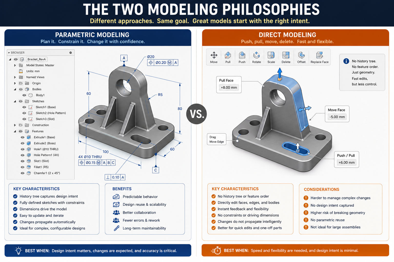
    The Two Modeling Philosophies Split illustration left side shows a structured parametric feature tree in a CAD tool with constraints and dimensions labeled; right side shows a designer directly pushing and pulling geometry faces on a 3D model with no visible history tree

    How Parametric Modeling Actually Works and Where Time Goes

    Parametric modeling is sometimes called history-based modeling because the CAD system maintains a chronological record of every operation you perform on the model. Each extrusion, cut, fillet, and hole is stored as a feature in the model’s feature tree, and each feature carries the parameters, dimensions, and constraints that define it. The model is not just a shape. It is a recipe for creating that shape, step by step, from the first sketch to the final detail.

    This structure is what gives parametric modeling its power. Change the wall thickness parameter and every feature that references it updates automatically. Change the base extrusion depth and the boss that sits on top of it moves with it. The whole model recomputes, top to bottom, every time a driving parameter changes. For designs that will be revised many times, this automation is enormously valuable.

    Where Parametric Modeling Spends Time Upfront

    The tradeoff is setup cost. Before you sketch the first profile, you need to think about how the model will behave when things change. Which reference planes will anchor the geometry? What parameters need to be named? In what order should features be created to minimize fragile parent-child dependencies? Getting this planning wrong does not just slow you down today. It creates problems on every future revision.

    An engineer experienced in parametric modeling will spend meaningful time at the start of any complex part setting up the framework: creating named parameters, planning the feature tree, establishing reference geometry. An inexperienced one will skip this phase, jump straight into sketching, and spend that time later untangling a broken model tree.

    The Time Debt Problem in Parametric Modeling

    Time debt is the hidden cost of parametric shortcuts. It accumulates every time an engineer hardcodes a value instead of using a parameter, references an unstable edge instead of a named plane, or builds a feature tree in the order geometry happens to be created rather than the order that makes logical and structural sense. The debt is invisible at the time the shortcuts are taken. It comes due on the first major revision.

    A parametric model with good discipline returns that upfront planning investment on the second engineering change order. A parametric model with poor discipline costs more time on every revision than a model rebuilt from scratch would have, because the engineer is constantly fighting a tree that was designed for a slightly different version of the part than the one they are now trying to make.

    Key Insight Parametric modeling does not automatically save time. Disciplined parametric modeling saves time. The approach itself is a multiplier: it amplifies good habits and amplifies poor ones equally. This is the fact that most comparison articles overlook entirely.

    How Direct Modeling Works and Where Its Speed Comes From

    Direct modeling takes a fundamentally different philosophy. Instead of building geometry through a recorded sequence of features, direct modeling lets you interact with the model’s faces, edges, and surfaces immediately, without any underlying history. Want to move a face? Drag it. Want to change the depth of a pocket? Pull the bottom face upward. Want to add a boss? Push geometry out from an existing surface.

    The result is an experience that feels closer to physical sculpting than to structured engineering. You are working on the shape directly, not on the recipe for producing the shape. There is no feature tree to manage, no parent-child dependencies to worry about, no risk of a downstream feature failing because you modified something upstream.

    Where Direct Modeling Genuinely Wins on Speed

    The speed advantage of direct modeling is most pronounced in three specific situations, and understanding these situations precisely is key to knowing when to reach for it.

    Concept exploration is where direct modeling shines brightest. When you are in the early stages of a design and you need to evaluate five different configurations rapidly, parametric setup overhead is pure friction. You are not yet sure which direction the design will go. Investing in constraints, named parameters, and feature tree planning for a concept that may be discarded entirely is time spent on infrastructure that will never be used. Direct modeling lets you generate rough geometry fast, reshape it freely, and explore the design space without commitment.

    Editing imported geometry is perhaps the clearest case for direct modeling in a professional engineering workflow. When you receive a STEP or IGES file from a supplier, a customer, or a legacy system, that file contains only geometry. There is no feature tree, no parametric history, no named dimensions. Importing it into a parametric modeler gives you a “dumb solid” that you cannot edit parametrically without first reverse-engineering the entire modeling sequence, which can take hours on a complex part.

    Direct modeling makes this a non-issue. You receive the STEP file, open it in a direct modeling environment, and immediately move faces, resize features, add or remove material, and prepare the model for whatever purpose you need, all without touching a feature tree or rebuilding parametric history.

    Late-stage minor changes that would trigger a parametric rebuild are a third scenario where direct modeling saves real time. If a fully completed parametric model needs a small cosmetic adjustment, a slight radius change, a face offset of two millimeters, a local chamfer added for ergonomic reasons, making that change parametrically may require navigating the entire feature tree, possibly editing a sketch buried ten levels deep, and resolving any rebuild warnings that cascade from the change. Direct modeling makes the same change in seconds: grab the face, offset it, done.

    Where Direct Modeling’s Speed Advantage Disappears

    The speed advantage of direct modeling is real but bounded. It disappears exactly when revisions become systematic rather than individual. If you need to change the wall thickness of every pocket in a complex housing from 3mm to 4mm, direct modeling requires you to find and edit every affected face individually. Parametric modeling with a named WallThickness parameter requires changing one value. The direct modeling approach scales linearly with complexity. The parametric approach does not scale at all.

    Documentation is another area where direct modeling creates downstream time costs that often exceed the time saved during initial geometry creation. Engineering drawings made from direct models frequently require manual re-dimensioning after geometry changes because there are no driving parameters to update automatically. In a production environment where drawings must be kept current through multiple revisions, this overhead adds up significantly.

    Real-World Scenario A product designer using SpaceClaim Direct Modeler completed a concept exploration phase for a consumer product in 40 percent of the time it would have taken in SolidWorks. Six weeks later, when the marketing team requested the product in three different sizes, the direct model provided no path to automated scaling. The parametric version, though slower to create initially, produced all three size variants in under two hours through a configuration table. The direct model required three separate rebuilds.

    The True Cost of a Broken Parametric Feature Tree

    No comparison of these two approaches is complete without an honest reckoning with one of parametric modeling’s most significant time costs: the broken feature tree. Every engineer who has worked in SolidWorks, Creo, CATIA, or Inventor knows the feeling. You make a change, hit rebuild, and watch a cascade of red error markers propagate down the feature tree. What should have been a five-minute dimension update turns into an hour of diagnostic work.

    This happens for predictable reasons: features referencing unstable geometry, sketches losing their constraint references after an upstream modification, circular dependencies created by poorly planned relationships. The model was brittle from the moment those modeling decisions were made, and the tree was waiting for the right change to expose the fragility.

    Quantifying the Rebuild Time Cost

    Experienced parametric modelers have developed strong instincts for building robust feature trees precisely because they have experienced the cost of rebuilding broken ones. But even with experience, feature tree failures happen. In a complex assembly with hundreds of parts, a single structural change can trigger rebuild failures across multiple components simultaneously, each of which requires individual diagnosis and repair.

    Direct modeling has no equivalent failure mode. There is no feature tree to break. A direct model edit either succeeds or it does not, and if it does not, the model is in its previous state. The engineer tries a different approach. The interaction is immediate and the failure, if it occurs, is local. There is no cascade.

    This is one of the genuine time advantages of direct modeling that receives too little attention in most comparisons: not just that direct edits are fast when they work, but that the failure mode when they do not work is contained and recoverable in seconds rather than minutes or hours.

    Preventing Feature Tree Failures in Parametric Models

    The right response to this risk is not to abandon parametric modeling but to model with enough discipline that tree failures become rare rather than routine. The practices that prevent feature tree failures are the same practices that make parametric models valuable in the first place: stable reference geometry, named parameters, logical feature ordering, and meaningful constraint strategy. A well-built parametric model rarely breaks, and when it does, the failure is usually isolated and traceable.

    • Use named planes and axes as references, never raw edges or vertices that may change shape
    • Keep the feature tree shallow and logical, with stable features at the top and detail at the bottom
    • Test the model’s behavior early by making intentional changes to driving parameters before the design is complete
    • Group and name features clearly so that any failure can be traced to its root cause quickly
    • Avoid circular references between features by planning the dependency chain before you build
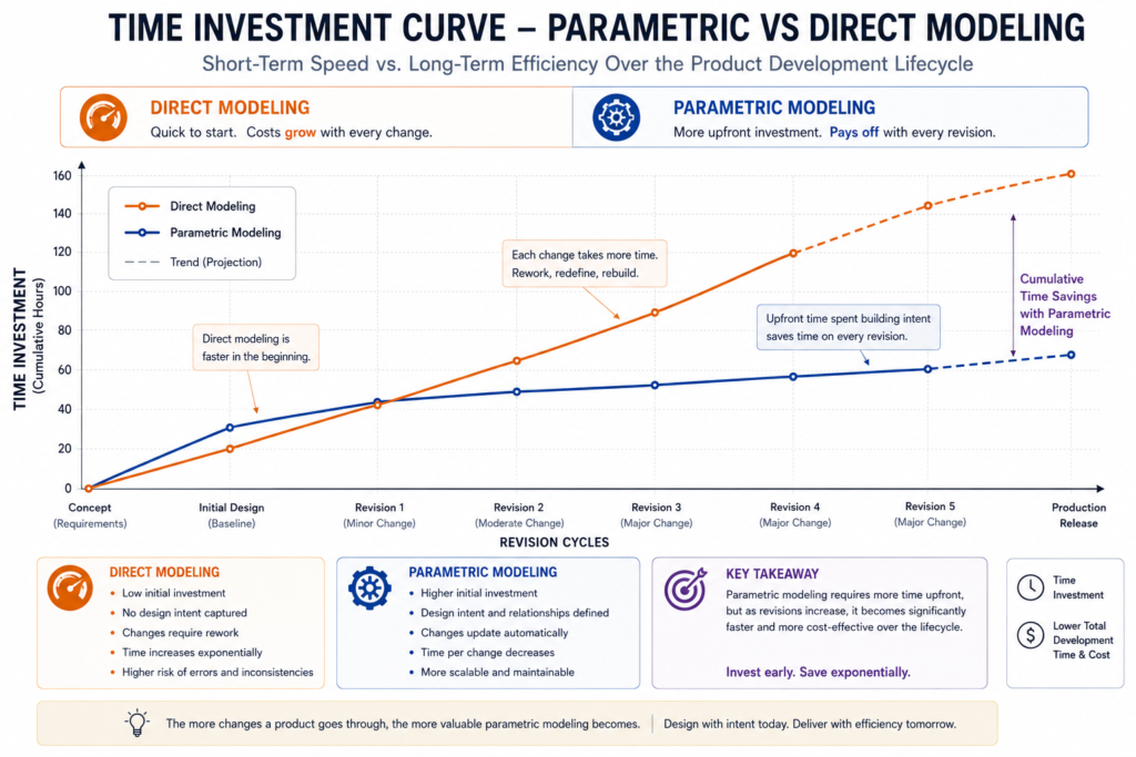
    Time Investment Curve - Parametric vs Direct Modeling

    Scenario-by-Scenario Time Comparison

    The most useful way to compare these two approaches is not through general principles but through specific scenarios. The following breakdown maps ten common engineering situations to the approach that saves more time and explains why. Use this as a practical reference, not a rigid rulebook.

    ScenarioParametricDirect ModelingTime Winner
    Initial concept modeling (first pass)Slower – constraints & setup requiredFaster – push/pull immediatelyDirect Modeling
    Making 10+ dimensional revisionsFast – change one parameter, propagatesSlow – each face edit is manualParametric
    Editing a STEP/IGES vendor fileVery slow – import rarely recovers treeFast – direct face edits no history neededDirect Modeling
    Managing a family of part variantsFast – configuration tables & equationsVery slow – must rebuild each variantParametric
    Late-stage cosmetic change (one feature)Medium – may trigger tree rebuildFast – move face instantlyDirect Modeling
    Assembly with 50+ parts, long lifecycleFast long-term – skeleton drives all partsVery slow – no propagation possibleParametric
    Preparing model for FEA / simulationMedium – may need defeature stepFast – direct defeaturing toolsDirect Modeling
    Documentation and drawing generationExcellent – dimensions auto-update in viewsPoor – manual re-dimension often neededParametric
    One-off bespoke part, no repeatSlower – setup overhead not recoveredFaster – no overheadDirect Modeling
    Recovering a broken feature treeVery slow – root cause investigation neededN/A – no tree to breakDirect Modeling
    Reading this table correctly is important. Direct modeling wins on the initial pass of most scenarios because setup overhead is zero. Parametric modeling catches and overtakes it starting from the first systematic revision. The crossover point, where parametric modeling becomes the net time saver, typically occurs after one to three major revisions depending on model complexity. For any design that will be revised more than twice, parametric modeling is almost always the better long-term investment.

    The Imported Geometry Problem: Where Direct Modeling Is Irreplaceable

    There is one scenario where direct modeling is not just faster but effectively the only practical option: working with imported CAD geometry that has no parametric history. This situation arises constantly in professional engineering, and how a team handles it has a significant impact on overall workflow efficiency.

    You receive a 3D model of a purchased component from a supplier as a STEP file. You receive a legacy design from a previous engineering team whose CAD tool is no longer in use. A customer sends you their existing housing geometry and asks you to design a mating component. In all of these cases, the file you receive is a collection of surfaces and solids with no feature tree, no parameters, no constraints, and no design history.

    The Parametric Import Challenge

    Importing this file into a parametric modeler gives you what engineers sometimes call a “dumb solid” or an “imported body”. Some parametric tools include feature recognition capabilities that attempt to identify and reconstruct parametric features from the imported geometry, but the results are typically incomplete. As the Kubotek Kosmos research on feature recognition demonstrated, a moderately complex imported chair model yielded only a fraction of its original features when processed through automatic recognition. Most of the geometry remained as unparameterized imported material.

    Editing a dumb solid in a parametric environment is a laborious process. You can add new parametric features on top of the imported body, but modifying the imported geometry itself requires workarounds: using move-face tools, deform features, or splitting and rebuilding sections. None of these feel native, and most are significantly slower than the same edit would be in a direct modeling environment.

    Direct Modeling as a Bridge

    Direct modeling makes imported geometry immediately editable. Open the STEP file, grab any face, resize any feature, add or remove material, and export a new STEP or IGES for downstream use. The entire workflow takes minutes instead of hours. For teams that work heavily with supplier-provided geometry, purchased component models, or cross-platform data exchange, this capability alone can justify maintaining a direct modeling tool alongside their primary parametric platform.

    Tools like Ansys SpaceClaim, Siemens NX, and the direct modeling environments within Fusion 360 are particularly strong in this area. They are used routinely by simulation engineers, manufacturing engineers, and tooling designers who need to modify received geometry without access to the original CAD tool or the parametric design history.

    Practical Workflow Note Many engineering teams maintain two tools: their primary parametric platform (SolidWorks, Creo, CATIA, Inventor) for in-house production design, and a direct modeling or hybrid tool (SpaceClaim, Fusion 360, NX) for working with external geometry. This is not redundancy. It is a deliberate workflow strategy that eliminates the dumb-solid bottleneck that otherwise consumes significant engineering hours.

    Hybrid Modeling: The Approach Most Articles Get Wrong

    Most articles on this topic conclude with a version of the same recommendation: use both methods. That advice is correct but almost entirely useless without specifics. Saying “use a hybrid approach” without explaining what that actually means in practice, which tool, which phase, which decision triggers the switch, leaves engineers exactly where they started.

    Hybrid modeling done correctly is not about owning two tools and picking between them randomly. It is a structured workflow where the choice of method at each phase is deliberate and informed by the nature of the work being done at that moment.

    Siemens Synchronous Technology: A True Hybrid

    Synchronous Technology, developed by Siemens for NX and Solid Edge, is the most sophisticated implementation of hybrid modeling currently available. It combines a live rules engine with direct face manipulation, allowing engineers to push and pull geometry while the software simultaneously applies dimensional and geometric rules to maintain design intent. The result is an environment that feels like direct modeling but behaves like parametric modeling: immediate, visual, free-form editing with automatic enforcement of the relationships that matter.

    Synchronous Technology is particularly powerful for modifying imported geometry. Unlike a conventional parametric import, synchronous modeling can infer and apply rules to imported faces, allowing meaningful parametric-like behavior even on geometry with no original design history. It is not as complete as a natively parametric model, but it is dramatically more powerful than a dumb solid in a conventional parametric environment.

    Fusion 360’s Timeline-Based Hybrid

    Autodesk Fusion 360 takes a different hybrid approach. Its timeline records the history of operations as in a parametric tool, but the modeling experience is more relaxed than traditional parametric tools, with direct manipulation options available alongside sketch-based parametric features. Designers can switch between the two modes within a single model, using direct modeling for quick geometry exploration and parametric features for the elements that need to be driven by equations and configurations.

    This workflow is particularly popular in product design and consumer electronics, where the design phase is highly iterative and the manufacturing phase benefits from fully defined parametric structure. Fusion 360 lets the model grow from an exploratory direct state into a production-ready parametric one without requiring a rebuild.

    A Practical Hybrid Decision Framework

    Use this as a starting point and adapt it to your specific context:

    • Concept and feasibility phase: Default to direct modeling or a hybrid tool. Speed of exploration matters more than structural discipline. Preserve only the geometry that survives into detailed design.
    • Detailed design phase: Switch to parametric modeling. Establish your feature tree, named parameters, and reference geometry before the design is finalized. The upfront investment pays back on every subsequent revision.
    • Working with external geometry: Use direct modeling exclusively. Do not attempt to parameterize imported files unless you have a specific reason to invest the time.
    • Late-stage minor changes: Assess the change. If it is isolated, localized, and cosmetic, a direct edit may be faster than navigating the parametric tree. If it is systemic, change the driving parameter.
    • Documentation and drawing creation: This phase almost always favors parametric models. Drawings made from direct models require more manual maintenance as the design evolves.

    Team Size and Collaboration: A Variable Nobody Talks About

    Almost every comparison of parametric versus direct modeling treats the engineer as a solo agent. The implicit assumption is that one person designs the model, one person revises it, and one person uses it. In reality, most production CAD work involves teams, handoffs, version control, and models that outlast the engineers who created them.

    Team size and collaboration structure are significant variables in the parametric versus direct time equation, and they consistently favor parametric modeling as team size grows.

    Why Direct Modeling Creates Team Friction

    A direct model edited by one engineer and then modified by a second engineer contains no record of why geometry is the way it is. The second engineer sees a shape. They do not see the design reasoning, the functional requirements, or the modeling sequence that produced the shape. Any modification they make is, in a real sense, a guess about what was intended and what can safely be changed.

    This problem is structurally worse than the same issue in parametric modeling. A parametric feature tree, even a poorly named one, at least documents the sequence of operations and the dimensions that drive them. An engineer encountering an unfamiliar parametric model can study the feature tree and develop a reasonable understanding of the design logic. A direct model offers none of this. The geometry is final. The reasoning is invisible.

    Parametric Models as Engineering Communication

    A well-built parametric model is a form of documentation. Named features, descriptive parameters, logical tree organization, and in-model annotations create a model that communicates design intent to every engineer who opens it, regardless of whether they were involved in creating it. This has real business value: shorter onboarding time, fewer errors in modifications, and lower risk when the original designer is unavailable.

    For any organization that expects CAD models to be maintained, modified, or referenced over a product lifecycle of more than a year, the documentation value of parametric modeling alone can justify its higher upfront time cost over direct modeling.

    Making the Decision: A Framework for Every Situation

    At this point the answer to the core question, which approach saves more time, should be clear in outline if not in every detail. Let us make it explicit and actionable.

    Choose Direct Modeling When:

    • You are exploring concepts or generating rough geometry for evaluation, not for production
    • You need to modify an imported STEP, IGES, or other vendor-provided file that has no parametric history
    • The part is a true one-off: it will be made once, never revised, never replicated in a family
    • You need to make a localized, cosmetic change to a completed model late in the design cycle
    • You are preparing models for FEA or simulation and need to defeature or simplify geometry quickly
    • Your tool is SpaceClaim, direct modeling NX, or another purpose-built direct environment

    Choose Parametric Modeling When:

    • The design will go through more than two major revision cycles
    • You need to produce a family of variants or configurations from a single master model
    • The model will be used to generate engineering drawings that must stay current through revisions
    • Multiple engineers will work on the model over its lifetime
    • The model will be reused as a starting point for future designs
    • Design intent needs to be captured and communicated to manufacturing, quality, and other downstream teams
    • You are designing a production part that will be manufactured in volume and will require ECO management

    Choose a Hybrid Approach When:

    • You are in a tool that supports both natively, such as Fusion 360, Siemens NX, or Solid Edge with Synchronous Technology
    • Your workflow moves from concept exploration into production design within the same project
    • You regularly receive and must modify external geometry as part of your design process
    • Your team includes both industrial designers who prioritize form and engineers who prioritize function
    The Answer to the Original Question Direct modeling saves more time in the first pass of concept work and in any situation involving imported geometry or isolated late-stage edits. Parametric modeling saves more time across the full design lifecycle of any part that will be revised, documented, and maintained. Hybrid modeling, used deliberately, saves the most time of all by deploying the right approach at the right phase without forcing a choice between them.

    Frequently Asked Questions

    Q: Is parametric modeling always slower than direct modeling at the start?

    Yes, typically. The upfront investment in setting up parameters, constraints, and reference geometry means parametric modeling takes longer to get to first geometry than direct modeling does. This cost is recovered on the first major revision, and every revision after that continues to return time savings. For designs with a long revision history, parametric modeling is almost always faster in aggregate.

    Q: Can you convert a direct model to a parametric model later?

    Technically yes, but practically it is rarely efficient to do so. Most parametric tools can import a direct model as a dumb solid, but this gives you only the final geometry, not the design logic. To get a truly parametric model from a direct one, an engineer typically has to reverse-engineer the modeling sequence and rebuild the part from scratch with parametric constraints. For complex parts, this can take as long as the original design took.

    Q: What CAD tools support both parametric and direct modeling?

    Several modern platforms offer hybrid capabilities: Autodesk Fusion 360, Siemens NX with Synchronous Technology, Siemens Solid Edge, PTC Creo with Flexible Modeling Extension, and Ansys SpaceClaim integrated into Discovery. Each implements the hybrid workflow differently, with Siemens Synchronous Technology being the most sophisticated in terms of real-time rule enforcement during direct edits.

    Q: Which approach is better for product design vs. mechanical engineering?

    Product design, especially in consumer goods and industrial design, tends to favor direct or hybrid modeling because the early phases involve high levels of form exploration where parametric overhead slows ideation. Mechanical engineering for production components almost always favors parametric modeling because of the revision, documentation, and family-of-parts requirements that come with manufactured products.

    Q: How does direct modeling handle assembly design?

    Direct modeling is significantly weaker than parametric modeling for assembly design. Without parametric relationships between parts, maintaining correct spatial relationships when geometry changes requires manual adjustment of each component affected by the change. For assemblies with more than a handful of parts, this becomes extremely time-consuming. Parametric assembly modeling, particularly with skeleton-driven approaches, propagates changes automatically across all dependent components.

    Q: What is synchronous technology in CAD?

    Synchronous Technology is a hybrid modeling approach developed by Siemens, available in NX and Solid Edge. It combines direct face manipulation with a live rules engine that enforces dimensional and geometric relationships in real time during edits. The result is an editing experience that feels immediate and visual like direct modeling but maintains design intent relationships like parametric modeling. It also makes imported geometry significantly more editable by inferring rules from geometric patterns in the imported model.

    Conclusion:

    The engineers who consistently deliver the fastest, highest-quality CAD work are not the ones who have chosen the “better” modeling approach and committed to it completely. They are the ones who understand both approaches well enough to make deliberate, informed decisions about which one to use at each phase of their work.

    Direct modeling is not a shortcut. It is a legitimate workflow tool that excels at concept exploration, imported geometry handling, and isolated late-stage edits. Parametric modeling is not bureaucratic overhead. It is the infrastructure that makes systematic revision, multi-variant design, and collaborative engineering efficient at scale. Both statements are true simultaneously.

    The question is not parametric or direct. The question is: what are you trying to accomplish in the next two hours, and which approach gets you there faster without creating problems you will pay for in the next two weeks? Answer that question correctly, and the time savings take care of themselves.

    If you are still primarily using one approach out of habit rather than deliberate choice, start there. Pick one project, apply both methods to the phases they are each suited for, and measure the result. The difference in workflow efficiency will make the argument for you more convincingly than any article can.

    Ready to deepen your CAD modeling skills? Explore our guides on design intent in parametric modeling, how to reduce CAD rework, and the top modeling mistakes that delay manufacturing.
  • Top CAD Modeling Mistakes That Delay Manufacturing

    Top CAD Modeling Mistakes That Delay Manufacturing

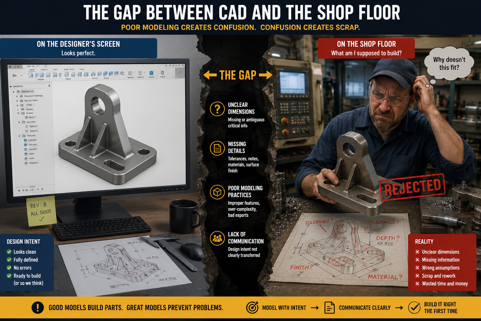
    The part looked perfect on screen. Clean geometry. Tight tolerances. No warnings in the model tree. It sailed through internal review and landed in the supplier’s inbox on a Friday afternoon. By Monday morning, there was an email back: the part could not be made as drawn. Three weeks later, after re-drawing, re-quoting, and re-ordering, production finally started. The launch date had already slipped.

    If that scenario sounds familiar, you are not alone. It is one of the most common and most expensive sequences of events in product development. And almost every step of that chain can be traced back to mistakes made during CAD modeling, not in manufacturing, not in engineering review, but at the source.

    The uncomfortable truth is that most CAD modeling mistakes that delay manufacturing are not caused by a lack of skill. They are caused by a lack of awareness: not knowing what the shop floor actually needs, not understanding how tolerances affect machinability, and not building models with the discipline that turns a digital design into a manufacturable part.

    This article covers the specific mistakes that create the most damage, why each one happens, what it costs when it reaches production, and exactly how to prevent it. Whether you are designing CNC machined components, injection-molded housings, sheet metal enclosures, or welded assemblies, these principles apply universally.

    Illustration showing a polished 3D CAD model on a designer's screen versus a confused machinist holding a rejected part on the shop floor, representing the gap poor modeling creates

    Modeling Without Manufacturing Process Knowledge

    This is the foundational mistake from which most other problems branch. When an engineer designs a part in CAD without a solid understanding of how that part will actually be made, the model becomes a collection of geometric shapes rather than a production-ready design. It may look correct, pass simulation, and satisfy the design brief on paper. But the moment it hits a real machine or mold tool, the gaps become painfully obvious.

    The CNC Machining Reality

    CNC machining has physical constraints that no CAD software will automatically enforce on your behalf. A deep pocket with a small corner radius might be trivial to draw in SolidWorks, but machining it requires a small-diameter end mill operating at significant depth, which means slow feeds, high tool deflection, and potential tool breakage. Some geometries are simply unreachable by any standard tooling path.

    Internal corners on a milled part will always have a radius at minimum equal to the cutter radius. If your design calls for a sharp internal 90-degree corner in a pocket, you either need to accept a radius, specify an undercut, or add a dog-bone relief. If none of these are shown on the drawing, the machinist has to stop and ask, and that question costs time and money every single time it happens.

    Injection Molding: The Draft Problem

    Draft angle is perhaps the single most common DFM error on injection-molded parts. Vertical walls, those with zero degrees of taper relative to the direction of mold opening, cause parts to stick in the tool. At best, this leaves cosmetic drag marks. At worst, it damages the mold and requires an expensive repair.

    Most injection-molded surfaces need a minimum of one to two degrees of draft. Complex or textured surfaces often need three degrees or more. This is not a detail you can add at the end as an afterthought. Draft must be designed in from the very beginning, because it affects the entire geometry of the part, where parting lines fall, how ribs are oriented, and whether wall thicknesses remain consistent.

    Sheet Metal: The Bend Radius and Proximity Rules

    Sheet metal design has its own set of manufacturing constraints that frequently get ignored in CAD. Holes placed too close to a bend distort during forming because the material stretches unpredictably in the bend zone. The minimum distance from a hole edge to a bend line is typically at least the material thickness plus the bend radius, and varies by material and gauge.

    K-factor, which describes how the neutral axis shifts during bending, must be correctly configured in your CAD tool for flat pattern development to be accurate. A flat pattern exported from a model with the wrong K-factor will produce parts that do not bend to the correct final angle. This error is invisible in the 3D model and only reveals itself when the bent part does not match the assembly.

    Real-World Cost A consumer electronics company discovered during first-article inspection that their injection-molded enclosure had zero draft on four internal bosses. The mold tool had already been cut. Adding draft required steel welding and re-cutting the tool, a process that added six weeks and approximately $18,000 to the program. The engineer who designed the model had never seen an injection mold run.

    Over-Tight Tolerances That Have Nothing to Do With Function

    Tolerance specification is where the gap between design intent and manufacturing cost becomes most visible, and most expensive. Over-tolerancing is not a minor inconvenience. It directly and measurably increases part cost, extends lead time, and in some cases makes a part entirely non-manufacturable through standard processes.

    The core problem is this: many engineers apply tight tolerances out of habit, caution, or training, without asking whether those tolerances are actually required by the function of the part. A tolerance of plus or minus 0.01 mm on a non-critical surface might feel like good engineering. But it requires specialized finishing operations, slower machining speeds, environmental temperature controls during inspection, and a CMM report for every part. The same surface at plus or minus 0.1 mm could be made on a standard CNC mill, inspected with a micrometer, and shipped the same week.

    What Over-Tight Tolerances Actually Cost

    The machining cost of a part is not linear with tolerance tightness. Tightening a tolerance from 0.1 mm to 0.01 mm does not make a part ten percent more expensive. Depending on the feature, it can double or triple the cost by pushing the part into grinding, lapping, or EDM territory rather than standard milling or turning. Add CMM inspection, rejection rates from tighter pass-fail criteria, and potential supplier qualification requirements, and the cost multiplier grows quickly.

    Lead time is equally affected. Standard tolerance parts often ship from a job shop in days. Precision tolerance parts enter a queue for specialized equipment, may require operator certification, and almost always require first-article approval before production quantities are released.

    The 7 Most Common Tolerance Mistakes Mechanical Engineers Make

    The Asymmetric Tolerance Trap

    There is a subtler tolerance error that creates problems even when the tolerance value itself is appropriate. Asymmetric tolerances modeled at a non-midpoint value cause parts to technically fall outside specification even when machined exactly to the CAD model. Consider a feature with a nominal dimension of 50 mm and a tolerance of plus 0 and minus 0.4 mm. The functional midpoint of this tolerance is 49.8 mm. If the CAD model shows 50 mm and the machinist cuts to the model exactly, the part sits at the tight end of the tolerance band, with essentially no margin.

    The correct practice is to model asymmetric tolerances at their statistical midpoint and apply the asymmetric annotation on the drawing. This way the model, the drawing, and the machining target all align, giving the machinist the full tolerance window to work within.

    How to Tolerance Correctly

    • Start with functional requirements: what actually needs to fit, move, or seal?
    • Apply standard machine tolerances (typically plus or minus 0.1 to 0.25 mm) to non-critical surfaces by default
    • Reserve tight tolerances (below 0.05 mm) for features that genuinely require them
    • Perform a tolerance stack-up analysis for critical assemblies before finalizing individual part tolerances
    • Review tolerances with a manufacturing engineer or supplier before releasing drawings

    Incomplete, Ambiguous, or Missing GD&T Annotations

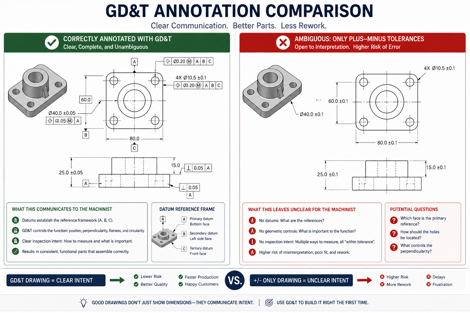
    Geometric Dimensioning and Tolerancing (GD&T) exists for a single purpose: to eliminate ambiguity in engineering drawings so that every machinist, inspector, and quality engineer understands exactly what the design requires without calling the design engineer. When GD&T is missing, incomplete, or incorrectly applied, that clarity disappears and the shop floor fills the gap with assumptions, and assumptions cost money.

    This is one of the most technically complex areas where CAD models fail manufacturing teams. GD&T errors do not always look like errors on the drawing. A drawing can appear professional, well-organized, and fully dimensioned while still containing GD&T annotations that are functionally ambiguous or outright incorrect.

    The Most Damaging GD&T Mistakes

    Datum selection errors are among the most common. A datum is the reference from which all other geometric controls are measured. If you select a datum that cannot be easily fixtured during machining or inspection, the shop cannot replicate the measurement environment you assumed during design. The resulting inspection data will be inconsistent, leading to parts being rejected that would have passed under a more sensible datum scheme, and vice versa.

    Position tolerances applied without datums create open-ended specifications. A position callout with no datum reference tells the inspector that a hole must be within a given tolerance zone but gives no reference for where that zone is located. The answer becomes dependent on how the inspector decides to set up the part, and two inspectors may produce different results from identical parts.

    Using plus-minus tolerancing where GD&T is needed is especially problematic for hole patterns and mating features. Plus-minus tolerancing creates a square tolerance zone, while GD&T true position creates a circular one. The circular zone is approximately 57 percent larger in area than the square zone for the same nominal tolerance value. This means plus-minus tolerancing on hole patterns is inherently more restrictive than true position GD&T, causing good parts to be rejected more often than necessary.

    Profile of a surface without datum references is a frequent error on complex curved parts. Without datums, the profile tolerance controls only form, not location or orientation. If the intent was to also control where that surface sits relative to other features, the callout is incomplete and the inspector has no way to verify the full requirement.

    Key Principle GD&T applied well reduces manufacturing cost by ensuring tolerances match functional requirements: no tighter, no looser. GD&T applied poorly can make drawings unnecessarily expensive to manufacture and inspect, and can cause perfectly good parts to be rejected because the annotation did not match the actual requirement.

    Practical Steps to Avoid GD&T Errors

    • Select datums based on how the part will be fixtured during machining and measured during inspection
    • Apply GD&T to surfaces and features that are functionally critical, not to every dimension
    • Use true position for hole patterns rather than coordinate plus-minus tolerances
    • Include datum references on all location and orientation controls
    • Have a manufacturing engineer or quality engineer review GD&T annotations before release
    • Reference ASME Y14.5-2018 as the governing standard for all drawings
    Side-by-side comparison of a correctly annotated engineering drawing with full GD&T versus an ambiguous drawing with only plus-minus tolerances, showing how each communicates to the machinist differently

    Sending the Wrong File Version to the Supplier

    This mistake does not get the attention it deserves in most CAD best-practice articles. It is discussed as a workflow issue, a PDM problem, a process failure. But make no mistake: sending a supplier an outdated file version is a CAD modeling problem as much as it is a data management problem, because the way CAD files are structured, named, and stored directly enables or prevents this mistake.

    Version control failures in engineering are far more common than most organizations admit. Engineers save files as “Housing_v3_FINAL_actually_final.SLDPRT” on shared drives. Email threads carry drawing attachments that quietly become outdated. A supplier quotes from a PDF sent three weeks ago and starts cutting from a model that has been revised twice since. The part that arrives is to the wrong specification, and no one realizes it until first-article inspection.

    What Happens When the Wrong Version Ships

    In the best case, the supplier catches the discrepancy and comes back with a question before cutting anything. This delays the order but costs only time. In the more common case, the supplier makes the part to the version they have. If the part happens to still assemble, the problem may never surface. If it does not assemble, or fails inspection, the cost is a rejected batch, a re-order, and a timeline slip. In safety-critical industries, it can trigger a recall and regulatory investigation.

    The design team spends hours trying to identify which version was sent, comparing files, checking email timestamps, and reconstructing a timeline of events. This forensic investigation is entirely avoidable.

    Building Version Control Into the CAD Workflow

    The solution is not just installing a PDM (Product Data Management) system and calling it done. PDM only works if engineers use it correctly, and they only use it correctly if the CAD models are structured in a way that makes version control natural rather than friction-heavy.

    This means establishing revision fields directly in the CAD model and drawing title block. It means releasing drawings only through a formal release process, not via email attachment. It means creating read-only PDF exports from the controlled master model, not from whatever file happens to be open at the time. And it means training the whole team, including purchasing and supplier management, to request and confirm revision levels on every procurement transaction.

    • Name files systematically: part number plus revision, never descriptive names with version keywords
    • Use a PDM or PLM system as the single source of truth for all released data
    • Lock released revisions so they cannot be edited without initiating a formal ECO
    • Archive all superseded revisions with a record of what changed and why
    • Transmit only controlled PDF or STEP exports to suppliers, never native CAD files unless contractually required

    Non-Manufacturable Geometry That Passes Visual Review

    This is perhaps the most insidious category of CAD modeling mistake because it is invisible to casual inspection. The model looks clean. No warnings in the feature tree. No red flags in the graphics window. It even passes a basic DFM check inside the CAD environment. Then it reaches a supplier’s CAM programmer, and the problems begin.

    Geometry That Cannot Be Tooled

    Inside corner radii that are too small for available tooling force the CAM programmer to use micro-end mills, which break frequently and require extremely slow feeds. Many job shops will simply decline a job with unachievable corner requirements, or quote a price that reflects the true cost of the work, which is often a shock to the design engineer who thought the geometry was routine.

    Features in blind holes or recessed pockets that cannot be reached by standard tooling lengths are another common problem. Designing a threaded feature at the bottom of a deep, narrow pocket looks fine in the 3D model, but tapping a thread at that depth and diameter combination may require a custom tap that adds weeks to procurement and significant cost to the unit price.

    Wall thicknesses below the minimum for the chosen process cause structural failure during or after manufacturing. In injection molding, walls that are too thin in proportion to their length produce short shots (incomplete fill) and warping. In CNC machining, thin walls chatter and flex under cutting forces, producing poor surface finish and dimensional inaccuracy. In casting, thin sections cool too quickly and create porosity or cold shuts.

    Zero-Thickness Faces and Non-Manifold Geometry

    This is a purely CAD-side problem with direct manufacturing consequences. Non-manifold geometry occurs when surfaces in a solid model share an edge but do not form a closed, water-tight solid. This kind of geometry appears visually normal in many CAD environments but produces errors when imported into CAM software or sent to a 3D printer. The toolpath algorithm cannot interpret the geometry correctly and either crashes, produces incorrect toolpaths, or outputs support structure in the wrong locations.

    Zero-thickness faces, often created by accidental coincident surfaces during Boolean operations, are similarly problematic. Run a geometry check tool in your CAD software before releasing any model. Most platforms (SolidWorks, Creo, CATIA, Inventor) have built-in geometry analysis tools that flag these problems. Use them.

    Quick Check Before releasing any model, run the following checks: solid body integrity check (no non-manifold edges), minimum wall thickness analysis, tool access simulation if available in your CAD tool, and a manual review of all internal radii against standard end mill sizes for your target process.

    Poor Assembly Mating Strategy Leading to Interference and Mis-Fits

    Assemblies that look correctly mated in CAD but fail to assemble in the real world are a major source of manufacturing delays, particularly in programs involving multiple suppliers, long lead-time components, or custom tooling. The physical parts arrive, they are brought together, and they do not fit because the CAD assembly did not accurately capture the geometric reality of the manufactured components.

    Mating to the Wrong Geometry

    One of the most common errors is mating components to each other’s nominal geometry without accounting for real-world variation. In a CAD assembly, a shaft and a bearing bore mate perfectly because both are modeled at their nominal dimension. In the real world, both have tolerance bands. If the tolerances are not analyzed collectively through a proper stack-up analysis, the assembled components may interfere under worst-case conditions or have excessive clearance under best-case conditions, either of which can cause functional failure.

    This is why tolerance analysis, particularly worst-case and statistical stack-up analysis, is not an optional step. For any assembly where fit affects function, it is a required part of the design process, and it must be informed by real manufacturing capability data, not just assumed tolerance values.

    Rigid Assemblies That Cannot Accommodate Real-World Variation

    Assemblies with zero degrees of freedom between mating parts and no designed-in compliance or adjustment are extremely sensitive to manufacturing variation. If every part must be at its exact nominal dimension for the assembly to close, any deviation in any component propagates directly into the assembly gap or interference. Real assemblies need shimming provisions, slotted holes for adjustment, or floating fastener strategies to absorb the natural variation that comes from real manufacturing processes.

    Slot a hole rather than a fixed hole where adjustment will be needed. Design shimming surfaces into housings where axial preload matters. Include provisions for adhesive or sealant in joints where surface variation is expected. These design choices do not cost money in manufacturing. They prevent it from being spent on field adjustment, rework, and warranty returns.

    Skipping Simulation and FEA Until It Is Too Late

    Simulation is the cheapest form of testing available to any engineering team, and yet it remains one of the most consistently under-used tools in product development. When FEA (Finite Element Analysis) and other simulation methods are deferred to late in the design cycle, the findings often require structural changes that cascade into tooling modifications, procurement re-orders, and schedule impacts that are entirely avoidable.

    The argument for deferring simulation is usually time: the model is not finalized yet, the loads are not confirmed, the material has not been selected. These are reasonable-sounding justifications that reflect a misunderstanding of how simulation adds value. Simulation does not need to be perfect to be useful. Even a simplified, conservative analysis early in the design cycle catches gross structural errors that would otherwise surface in physical testing.

    What Late Simulation Discovery Costs

    An injection-molded structural housing that fails a drop test after tooling is cut requires one of three responses: accept reduced performance (if the customer and regulatory environment allow it), add material with insert tooling (possible for minor corrections, expensive for major ones), or recut the tool (very expensive, often measured in tens of thousands of dollars and multiple weeks). All three options are downstream consequences of a simulation that was not run, or not run seriously, during design.

    Compare this to the same problem caught during initial CAD modeling. The engineer thickens the wall, adds a rib, changes the material specification, or redesigns the load path. The CAD file is updated in hours. No tooling money has been spent. No schedule has been impacted.

    Integrating Simulation Into the Design Phase

    • Run initial topology optimization or hand calculations as soon as a concept is selected, before detailed modeling begins
    • Use built-in CAD simulation tools (SolidWorks Simulation, Inventor Nastran, Creo Simulate) for early screening, even on simplified models
    • Run a dedicated FEA review at each major design milestone, not just at the end
    • Include thermal simulation for any component exposed to significant heat sources or cycling
    • Use mold flow analysis for injection-molded parts before finalizing tool design
    • Document simulation assumptions and results as part of the design record

    Using Unstable CAD References That Break on Update

    This mistake lives purely in the CAD environment, but its consequences reach directly into manufacturing timelines. Unstable CAD references are references between features, sketches, or assembly components that are anchored to geometry that is likely to change or disappear: a specific edge, a vertex that results from an intersection, a face that changes shape when an earlier feature is modified.

    When that reference geometry changes, the feature or assembly constraint that references it fails. In some cases the failure is obvious: the model throws an error and the feature turns red in the tree. In other cases the failure is silent: the geometry updates, but not to the correct position, producing a subtly wrong model that passes visual inspection but has incorrect dimensions.

    Why Silent Failures Are the Most Dangerous

    A model that fails loudly is annoying but manageable. The engineer sees the error and investigates. A model that fails silently produces incorrect geometry that flows downstream into drawings, STEP exports, and eventually into the supplier’s CAM program. By the time the error is discovered, parts may already be in production or, worse, already delivered and assembled into a product.

    Silent reference failures are especially common when features reference edges that are created by intersection of two surfaces, because when either of those surfaces changes, the intersection edge changes position, shape, or may disappear entirely. The feature referencing that edge silently moves to the new edge location, or fails to resolve and uses the last known position.

    Building Reference Stability Into Your Workflow

    • Reference named planes, axes, and coordinate systems rather than edges or vertices wherever possible
    • Create dedicated reference geometry at the top of your feature tree for all key datum surfaces
    • Avoid referencing geometry from other parts in an assembly context unless you are using a controlled top-down skeleton approach
    • After any major model update, run a full geometry analysis and check all mating surfaces and critical dimensions explicitly
    • Use design freeze checkpoints: formally lock reference geometry after each major design phase

    The Design-Manufacturing Communication Wall

    This final mistake is the most human of all, and arguably the one that causes the most cumulative damage. The wall between the design engineering team and the manufacturing team, whether that is an internal production group or an external supplier, is where the majority of preventable delays are born.

    Design engineers optimize for performance, aesthetics, and functional requirements. Manufacturing engineers optimize for process capability, tooling efficiency, and cycle time. These goals are not inherently in conflict, but when the two groups do not communicate during the design phase, they produce solutions optimized for their respective silos that fail at the boundary where those silos meet.

    The Downstream Review Problem

    In many organizations, manufacturing review happens after the design is considered complete: at the DFM review, at the pre-production meeting, or at the quotation stage with suppliers. At this point, the design has been invested in. The engineer has spent weeks building the model. Management has committed to a schedule based on this design. Changing it now is expensive in every sense of the word: politically, financially, and temporally.

    The better model is concurrent engineering: involving manufacturing engineers, tooling engineers, and key suppliers in the design process while fundamental choices are still being made. This is not a new idea. It has been known to reduce time-to-market and engineering change orders significantly in organizations that practice it consistently. The barrier is cultural, not technical.

    What Design Engineers Can Do Right Now

    • Share in-progress CAD models with manufacturing stakeholders early, not polished ones. Ask for feedback on process feasibility, not visual appearance.
    • Create a DFM checklist specific to your manufacturing processes and run through it before every design review, not at the final release stage.
    • Visit the shop floor at least once during each major program. Understanding what a machinist sees when they read your drawing changes how you draw.
    • Request supplier DFM feedback at quotation stage and treat it as engineering input, not as a negotiating inconvenience.
    • Document manufacturing constraints in the CAD model using annotations and notes, so the information travels with the file rather than existing only in the engineer’s head.

    Quick Reference: CAD Mistakes vs. Shop Floor Impact

    The table below maps each major mistake category to its manufacturing consequence, delay severity, and the primary prevention tool available to the design engineer.

    CAD MistakeShop Floor ImpactDelay SeverityPrevention Tool
    Ignoring DFM principlesToolpath failures, scrapped partsHighDFM checklist, CAM simulation
    Over-tight tolerancesMachining time spikes, high scrap rateHighTolerance stack-up analysis
    Missing/vague GD&TInspector guesswork, rejected partsHighASME Y14.5 annotation review
    Unstable CAD referencesModel rebuild failures, wrong geometryMedium-HighReference plane strategy
    Wrong file version to supplierParts made to old spec, re-order neededVery HighPDM / version control system
    No draft on injection-molded partsParts stuck in tool, mold damageHighMold flow simulation
    Thin walls below process limitsWarp, sink marks, structural failureMediumProcess-specific DFM rules
    Hardcoded dimensions, no parametersManual rework on every revisionMediumNamed parameters, equations
    Poor assembly mating strategyInterference at build, mis-fitsHighAssembly analysis, DMU
    Skipping simulation / FEA earlyLate-stage structural failure discoveryVery HighIntegrated FEA in design phase

    Use this table as a pre-release checklist before any design reaches manufacturing. Catching even one of these mistakes at the CAD stage eliminates a delay that, once it reaches the shop floor, is guaranteed to be larger, more expensive, and harder to explain.

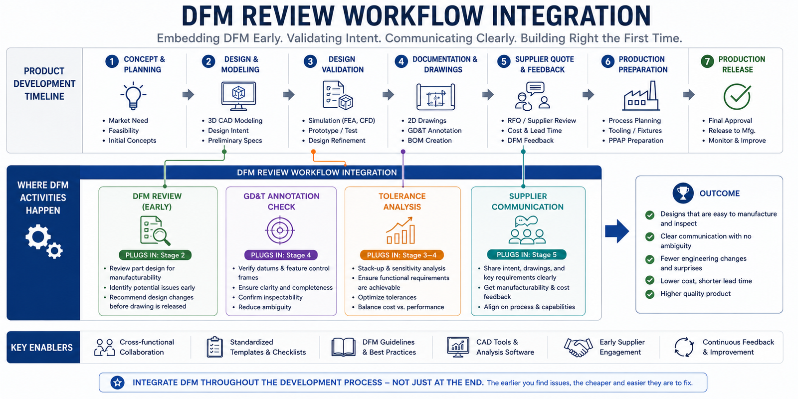
    Flowchart showing where DFM review, GD&T annotation check, tolerance analysis, and supplier communication should sit within a typical product development timeline, from concept through production release

    Frequently Asked Questions

    Q: What are the most common CAD modeling mistakes that delay manufacturing?

    A: The most common mistakes include designing without process knowledge (no draft for molding, wrong corner radii for machining), applying unnecessarily tight tolerances, incomplete or ambiguous GD&T annotations, sending wrong file versions to suppliers, non-manifold or non-manufacturable geometry, and skipping simulation until late in the design cycle. Each of these can be prevented with targeted workflow practices.

    Q: How does over-tolerancing affect manufacturing lead time?

    A: Over-tolerancing pushes parts into specialized machining territory: grinding, lapping, or EDM processes rather than standard milling or turning. It also requires CMM inspection rather than standard gauging, adds operator qualification requirements, and increases rejection rates. Tight tolerances that are not functionally required can double or triple part cost and extend lead time from days to weeks.

    Q: What is design for manufacturability (DFM) and when should it happen?

    A: DFM is the practice of designing parts and assemblies with the manufacturing process in mind, so that production is efficient, low-cost, and high-quality. It should begin at the concept selection stage, not as a final review before release. Key DFM principles include matching geometry to process capabilities, designing appropriate tolerances, and involving manufacturing engineers in design decisions early.

    Q: Why do parts that look correct in CAD fail when manufactured?

    A: CAD models represent nominal geometry with no manufacturing variation, no tool deflection, no material springback, and no thermal effects. A part can look geometrically correct in the model while containing features that are impossible to tool, tolerances that require non-standard processes, or references that produce incorrect geometry after updates. Running DFM analysis, geometry checks, and tolerance stack-ups helps bridge this gap.

    Q: How can engineers prevent sending wrong CAD file versions to suppliers?

    A: Implement a PDM or PLM system as the single source of truth. Release drawings only through a formal revision control process. Use part number and revision level as file names, not descriptive names with version keywords. Transmit only controlled exports (PDF, STEP) to suppliers and confirm revision level on every transaction. Never send native CAD files via email as the primary manufacturing reference.

    Q: What is the difference between GD&T and plus-minus tolerancing?

    A: Plus-minus tolerancing assigns independent linear variation to each dimension, creating square tolerance zones for positioned features. GD&T uses a standardized symbolic language to define shape, orientation, location, and size variation with geometric precision. GD&T true position, for example, creates a circular tolerance zone that is approximately 57 percent larger than an equivalent square coordinate zone, meaning GD&T is simultaneously more precise in intent and more generous to the machinist when applied correctly.

    Conclusion:

    Every mistake in this article has one thing in common: it is dramatically cheaper to fix at the CAD stage than at any later point in the production process. The cost of changing a draft angle in a CAD model is ten minutes of an engineer’s time. The cost of correcting that same issue after a mold tool has been cut is tens of thousands of dollars and several weeks of schedule.

    This is not a theoretical observation. It is the engineering principle behind concurrent design and DFM: the earlier a problem is identified, the cheaper it is to fix. And the CAD model is the earliest possible intervention point before any physical resources are committed.

    The engineers who consistently produce manufacturing-ready CAD models are not necessarily more talented than those who do not. They are simply more deliberate. They think about the shop floor while they are still in front of the screen. They know their manufacturing processes, or they talk to people who do. They apply tolerances that serve function rather than instinct. They check geometry before they release. They communicate with suppliers early rather than late.

    These habits are learnable. They compound over time. And they transform a CAD model from a design artifact into a manufacturing asset.

    Want to go deeper? Explore our guides on design intent in CAD, GD&T fundamentals, parametric modeling best practices, and DFM checklists for your specific manufacturing process.