Ask ten engineers which CAD modeling approach saves more time and you will get ten different answers, most of them shaped by whichever tool they learned first and the type of work they do most. Parametric modelers will tell you that direct modeling is a shortcut that creates technical debt. Direct modelers will say that parametric workflows bury you in feature management overhead before you have even validated the concept.
Both groups are right. And both groups are wrong. The reason this debate never gets resolved cleanly is that most articles comparing these two approaches ask the wrong question. They ask which method is better in general. The correct question is: which method saves more time in which specific situation? The answer changes dramatically depending on where you are in the product development process, how complex your model is, how many revisions you expect, and how the model will ultimately be used.
This article answers that question with specificity. We will cover how each approach actually works, where each one spends and saves engineering time, which scenarios definitively favor one over the other, and why the most productive CAD engineers do not choose between them but learn to deploy both strategically. By the end, you will have a decision framework you can apply to your very next project.
How Parametric Modeling Actually Works and Where Time Goes
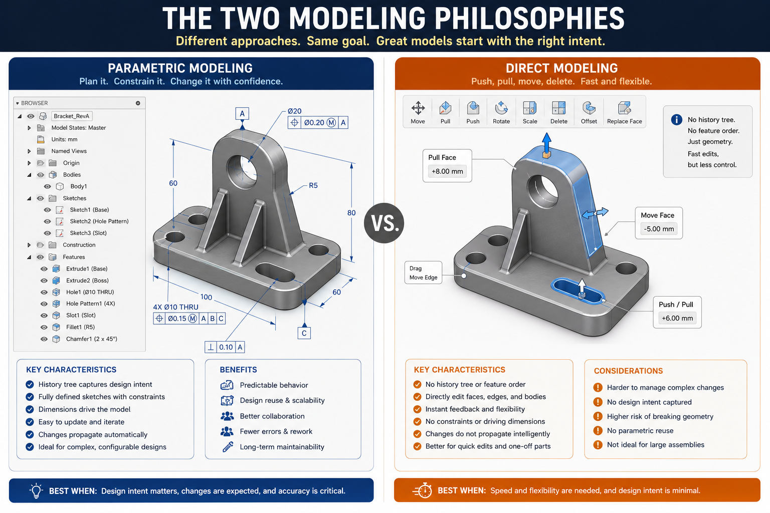
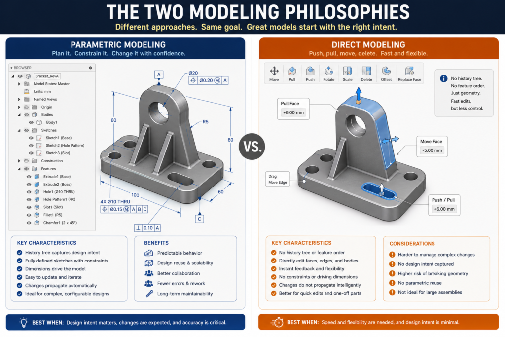
Parametric modeling is sometimes called history-based modeling because the CAD system maintains a chronological record of every operation you perform on the model. Each extrusion, cut, fillet, and hole is stored as a feature in the model’s feature tree, and each feature carries the parameters, dimensions, and constraints that define it. The model is not just a shape. It is a recipe for creating that shape, step by step, from the first sketch to the final detail.
This structure is what gives parametric modeling its power. Change the wall thickness parameter and every feature that references it updates automatically. Change the base extrusion depth and the boss that sits on top of it moves with it. The whole model recomputes, top to bottom, every time a driving parameter changes. For designs that will be revised many times, this automation is enormously valuable.
Where Parametric Modeling Spends Time Upfront
The tradeoff is setup cost. Before you sketch the first profile, you need to think about how the model will behave when things change. Which reference planes will anchor the geometry? What parameters need to be named? In what order should features be created to minimize fragile parent-child dependencies? Getting this planning wrong does not just slow you down today. It creates problems on every future revision.
An engineer experienced in parametric modeling will spend meaningful time at the start of any complex part setting up the framework: creating named parameters, planning the feature tree, establishing reference geometry. An inexperienced one will skip this phase, jump straight into sketching, and spend that time later untangling a broken model tree.
The Time Debt Problem in Parametric Modeling
Time debt is the hidden cost of parametric shortcuts. It accumulates every time an engineer hardcodes a value instead of using a parameter, references an unstable edge instead of a named plane, or builds a feature tree in the order geometry happens to be created rather than the order that makes logical and structural sense. The debt is invisible at the time the shortcuts are taken. It comes due on the first major revision.
A parametric model with good discipline returns that upfront planning investment on the second engineering change order. A parametric model with poor discipline costs more time on every revision than a model rebuilt from scratch would have, because the engineer is constantly fighting a tree that was designed for a slightly different version of the part than the one they are now trying to make.
| Key Insight Parametric modeling does not automatically save time. Disciplined parametric modeling saves time. The approach itself is a multiplier: it amplifies good habits and amplifies poor ones equally. This is the fact that most comparison articles overlook entirely. |
How Direct Modeling Works and Where Its Speed Comes From
Direct modeling takes a fundamentally different philosophy. Instead of building geometry through a recorded sequence of features, direct modeling lets you interact with the model’s faces, edges, and surfaces immediately, without any underlying history. Want to move a face? Drag it. Want to change the depth of a pocket? Pull the bottom face upward. Want to add a boss? Push geometry out from an existing surface.
The result is an experience that feels closer to physical sculpting than to structured engineering. You are working on the shape directly, not on the recipe for producing the shape. There is no feature tree to manage, no parent-child dependencies to worry about, no risk of a downstream feature failing because you modified something upstream.
Where Direct Modeling Genuinely Wins on Speed
The speed advantage of direct modeling is most pronounced in three specific situations, and understanding these situations precisely is key to knowing when to reach for it.
Concept exploration is where direct modeling shines brightest. When you are in the early stages of a design and you need to evaluate five different configurations rapidly, parametric setup overhead is pure friction. You are not yet sure which direction the design will go. Investing in constraints, named parameters, and feature tree planning for a concept that may be discarded entirely is time spent on infrastructure that will never be used. Direct modeling lets you generate rough geometry fast, reshape it freely, and explore the design space without commitment.
Editing imported geometry is perhaps the clearest case for direct modeling in a professional engineering workflow. When you receive a STEP or IGES file from a supplier, a customer, or a legacy system, that file contains only geometry. There is no feature tree, no parametric history, no named dimensions. Importing it into a parametric modeler gives you a “dumb solid” that you cannot edit parametrically without first reverse-engineering the entire modeling sequence, which can take hours on a complex part.
Direct modeling makes this a non-issue. You receive the STEP file, open it in a direct modeling environment, and immediately move faces, resize features, add or remove material, and prepare the model for whatever purpose you need, all without touching a feature tree or rebuilding parametric history.
Late-stage minor changes that would trigger a parametric rebuild are a third scenario where direct modeling saves real time. If a fully completed parametric model needs a small cosmetic adjustment, a slight radius change, a face offset of two millimeters, a local chamfer added for ergonomic reasons, making that change parametrically may require navigating the entire feature tree, possibly editing a sketch buried ten levels deep, and resolving any rebuild warnings that cascade from the change. Direct modeling makes the same change in seconds: grab the face, offset it, done.
Where Direct Modeling’s Speed Advantage Disappears
The speed advantage of direct modeling is real but bounded. It disappears exactly when revisions become systematic rather than individual. If you need to change the wall thickness of every pocket in a complex housing from 3mm to 4mm, direct modeling requires you to find and edit every affected face individually. Parametric modeling with a named WallThickness parameter requires changing one value. The direct modeling approach scales linearly with complexity. The parametric approach does not scale at all.
Documentation is another area where direct modeling creates downstream time costs that often exceed the time saved during initial geometry creation. Engineering drawings made from direct models frequently require manual re-dimensioning after geometry changes because there are no driving parameters to update automatically. In a production environment where drawings must be kept current through multiple revisions, this overhead adds up significantly.
| Real-World Scenario A product designer using SpaceClaim Direct Modeler completed a concept exploration phase for a consumer product in 40 percent of the time it would have taken in SolidWorks. Six weeks later, when the marketing team requested the product in three different sizes, the direct model provided no path to automated scaling. The parametric version, though slower to create initially, produced all three size variants in under two hours through a configuration table. The direct model required three separate rebuilds. |
The True Cost of a Broken Parametric Feature Tree
No comparison of these two approaches is complete without an honest reckoning with one of parametric modeling’s most significant time costs: the broken feature tree. Every engineer who has worked in SolidWorks, Creo, CATIA, or Inventor knows the feeling. You make a change, hit rebuild, and watch a cascade of red error markers propagate down the feature tree. What should have been a five-minute dimension update turns into an hour of diagnostic work.
This happens for predictable reasons: features referencing unstable geometry, sketches losing their constraint references after an upstream modification, circular dependencies created by poorly planned relationships. The model was brittle from the moment those modeling decisions were made, and the tree was waiting for the right change to expose the fragility.
Quantifying the Rebuild Time Cost
Experienced parametric modelers have developed strong instincts for building robust feature trees precisely because they have experienced the cost of rebuilding broken ones. But even with experience, feature tree failures happen. In a complex assembly with hundreds of parts, a single structural change can trigger rebuild failures across multiple components simultaneously, each of which requires individual diagnosis and repair.
Direct modeling has no equivalent failure mode. There is no feature tree to break. A direct model edit either succeeds or it does not, and if it does not, the model is in its previous state. The engineer tries a different approach. The interaction is immediate and the failure, if it occurs, is local. There is no cascade.
This is one of the genuine time advantages of direct modeling that receives too little attention in most comparisons: not just that direct edits are fast when they work, but that the failure mode when they do not work is contained and recoverable in seconds rather than minutes or hours.
Preventing Feature Tree Failures in Parametric Models
The right response to this risk is not to abandon parametric modeling but to model with enough discipline that tree failures become rare rather than routine. The practices that prevent feature tree failures are the same practices that make parametric models valuable in the first place: stable reference geometry, named parameters, logical feature ordering, and meaningful constraint strategy. A well-built parametric model rarely breaks, and when it does, the failure is usually isolated and traceable.
- Use named planes and axes as references, never raw edges or vertices that may change shape
- Keep the feature tree shallow and logical, with stable features at the top and detail at the bottom
- Test the model’s behavior early by making intentional changes to driving parameters before the design is complete
- Group and name features clearly so that any failure can be traced to its root cause quickly
- Avoid circular references between features by planning the dependency chain before you build
Scenario-by-Scenario Time Comparison
The most useful way to compare these two approaches is not through general principles but through specific scenarios. The following breakdown maps ten common engineering situations to the approach that saves more time and explains why. Use this as a practical reference, not a rigid rulebook.
| Scenario | Parametric | Direct Modeling | Time Winner |
| Initial concept modeling (first pass) | Slower – constraints & setup required | Faster – push/pull immediately | Direct Modeling |
| Making 10+ dimensional revisions | Fast – change one parameter, propagates | Slow – each face edit is manual | Parametric |
| Editing a STEP/IGES vendor file | Very slow – import rarely recovers tree | Fast – direct face edits no history needed | Direct Modeling |
| Managing a family of part variants | Fast – configuration tables & equations | Very slow – must rebuild each variant | Parametric |
| Late-stage cosmetic change (one feature) | Medium – may trigger tree rebuild | Fast – move face instantly | Direct Modeling |
| Assembly with 50+ parts, long lifecycle | Fast long-term – skeleton drives all parts | Very slow – no propagation possible | Parametric |
| Preparing model for FEA / simulation | Medium – may need defeature step | Fast – direct defeaturing tools | Direct Modeling |
| Documentation and drawing generation | Excellent – dimensions auto-update in views | Poor – manual re-dimension often needed | Parametric |
| One-off bespoke part, no repeat | Slower – setup overhead not recovered | Faster – no overhead | Direct Modeling |
| Recovering a broken feature tree | Very slow – root cause investigation needed | N/A – no tree to break | Direct Modeling |
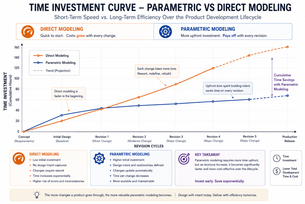
| Reading this table correctly is important. Direct modeling wins on the initial pass of most scenarios because setup overhead is zero. Parametric modeling catches and overtakes it starting from the first systematic revision. The crossover point, where parametric modeling becomes the net time saver, typically occurs after one to three major revisions depending on model complexity. For any design that will be revised more than twice, parametric modeling is almost always the better long-term investment. |
The Imported Geometry Problem: Where Direct Modeling Is Irreplaceable
There is one scenario where direct modeling is not just faster but effectively the only practical option: working with imported CAD geometry that has no parametric history. This situation arises constantly in professional engineering, and how a team handles it has a significant impact on overall workflow efficiency.
You receive a 3D model of a purchased component from a supplier as a STEP file. You receive a legacy design from a previous engineering team whose CAD tool is no longer in use. A customer sends you their existing housing geometry and asks you to design a mating component. In all of these cases, the file you receive is a collection of surfaces and solids with no feature tree, no parameters, no constraints, and no design history.
The Parametric Import Challenge
Importing this file into a parametric modeler gives you what engineers sometimes call a “dumb solid” or an “imported body”. Some parametric tools include feature recognition capabilities that attempt to identify and reconstruct parametric features from the imported geometry, but the results are typically incomplete. As the Kubotek Kosmos research on feature recognition demonstrated, a moderately complex imported chair model yielded only a fraction of its original features when processed through automatic recognition. Most of the geometry remained as unparameterized imported material.
Editing a dumb solid in a parametric environment is a laborious process. You can add new parametric features on top of the imported body, but modifying the imported geometry itself requires workarounds: using move-face tools, deform features, or splitting and rebuilding sections. None of these feel native, and most are significantly slower than the same edit would be in a direct modeling environment.
Direct Modeling as a Bridge
Direct modeling makes imported geometry immediately editable. Open the STEP file, grab any face, resize any feature, add or remove material, and export a new STEP or IGES for downstream use. The entire workflow takes minutes instead of hours. For teams that work heavily with supplier-provided geometry, purchased component models, or cross-platform data exchange, this capability alone can justify maintaining a direct modeling tool alongside their primary parametric platform.
Tools like Ansys SpaceClaim, Siemens NX, and the direct modeling environments within Fusion 360 are particularly strong in this area. They are used routinely by simulation engineers, manufacturing engineers, and tooling designers who need to modify received geometry without access to the original CAD tool or the parametric design history.
| Practical Workflow Note Many engineering teams maintain two tools: their primary parametric platform (SolidWorks, Creo, CATIA, Inventor) for in-house production design, and a direct modeling or hybrid tool (SpaceClaim, Fusion 360, NX) for working with external geometry. This is not redundancy. It is a deliberate workflow strategy that eliminates the dumb-solid bottleneck that otherwise consumes significant engineering hours. |
Hybrid Modeling: The Approach Most Articles Get Wrong
Most articles on this topic conclude with a version of the same recommendation: use both methods. That advice is correct but almost entirely useless without specifics. Saying “use a hybrid approach” without explaining what that actually means in practice, which tool, which phase, which decision triggers the switch, leaves engineers exactly where they started.
Hybrid modeling done correctly is not about owning two tools and picking between them randomly. It is a structured workflow where the choice of method at each phase is deliberate and informed by the nature of the work being done at that moment.
Siemens Synchronous Technology: A True Hybrid
Synchronous Technology, developed by Siemens for NX and Solid Edge, is the most sophisticated implementation of hybrid modeling currently available. It combines a live rules engine with direct face manipulation, allowing engineers to push and pull geometry while the software simultaneously applies dimensional and geometric rules to maintain design intent. The result is an environment that feels like direct modeling but behaves like parametric modeling: immediate, visual, free-form editing with automatic enforcement of the relationships that matter.
Synchronous Technology is particularly powerful for modifying imported geometry. Unlike a conventional parametric import, synchronous modeling can infer and apply rules to imported faces, allowing meaningful parametric-like behavior even on geometry with no original design history. It is not as complete as a natively parametric model, but it is dramatically more powerful than a dumb solid in a conventional parametric environment.
Fusion 360’s Timeline-Based Hybrid
Autodesk Fusion 360 takes a different hybrid approach. Its timeline records the history of operations as in a parametric tool, but the modeling experience is more relaxed than traditional parametric tools, with direct manipulation options available alongside sketch-based parametric features. Designers can switch between the two modes within a single model, using direct modeling for quick geometry exploration and parametric features for the elements that need to be driven by equations and configurations.
This workflow is particularly popular in product design and consumer electronics, where the design phase is highly iterative and the manufacturing phase benefits from fully defined parametric structure. Fusion 360 lets the model grow from an exploratory direct state into a production-ready parametric one without requiring a rebuild.
A Practical Hybrid Decision Framework
Use this as a starting point and adapt it to your specific context:
- Concept and feasibility phase: Default to direct modeling or a hybrid tool. Speed of exploration matters more than structural discipline. Preserve only the geometry that survives into detailed design.
- Detailed design phase: Switch to parametric modeling. Establish your feature tree, named parameters, and reference geometry before the design is finalized. The upfront investment pays back on every subsequent revision.
- Working with external geometry: Use direct modeling exclusively. Do not attempt to parameterize imported files unless you have a specific reason to invest the time.
- Late-stage minor changes: Assess the change. If it is isolated, localized, and cosmetic, a direct edit may be faster than navigating the parametric tree. If it is systemic, change the driving parameter.
- Documentation and drawing creation: This phase almost always favors parametric models. Drawings made from direct models require more manual maintenance as the design evolves.
Team Size and Collaboration: A Variable Nobody Talks About
Almost every comparison of parametric versus direct modeling treats the engineer as a solo agent. The implicit assumption is that one person designs the model, one person revises it, and one person uses it. In reality, most production CAD work involves teams, handoffs, version control, and models that outlast the engineers who created them.
Team size and collaboration structure are significant variables in the parametric versus direct time equation, and they consistently favor parametric modeling as team size grows.
Why Direct Modeling Creates Team Friction
A direct model edited by one engineer and then modified by a second engineer contains no record of why geometry is the way it is. The second engineer sees a shape. They do not see the design reasoning, the functional requirements, or the modeling sequence that produced the shape. Any modification they make is, in a real sense, a guess about what was intended and what can safely be changed.
This problem is structurally worse than the same issue in parametric modeling. A parametric feature tree, even a poorly named one, at least documents the sequence of operations and the dimensions that drive them. An engineer encountering an unfamiliar parametric model can study the feature tree and develop a reasonable understanding of the design logic. A direct model offers none of this. The geometry is final. The reasoning is invisible.
Parametric Models as Engineering Communication
A well-built parametric model is a form of documentation. Named features, descriptive parameters, logical tree organization, and in-model annotations create a model that communicates design intent to every engineer who opens it, regardless of whether they were involved in creating it. This has real business value: shorter onboarding time, fewer errors in modifications, and lower risk when the original designer is unavailable.
For any organization that expects CAD models to be maintained, modified, or referenced over a product lifecycle of more than a year, the documentation value of parametric modeling alone can justify its higher upfront time cost over direct modeling.
Making the Decision: A Framework for Every Situation
At this point the answer to the core question, which approach saves more time, should be clear in outline if not in every detail. Let us make it explicit and actionable.
Choose Direct Modeling When:
- You are exploring concepts or generating rough geometry for evaluation, not for production
- You need to modify an imported STEP, IGES, or other vendor-provided file that has no parametric history
- The part is a true one-off: it will be made once, never revised, never replicated in a family
- You need to make a localized, cosmetic change to a completed model late in the design cycle
- You are preparing models for FEA or simulation and need to defeature or simplify geometry quickly
- Your tool is SpaceClaim, direct modeling NX, or another purpose-built direct environment
Choose Parametric Modeling When:
- The design will go through more than two major revision cycles
- You need to produce a family of variants or configurations from a single master model
- The model will be used to generate engineering drawings that must stay current through revisions
- Multiple engineers will work on the model over its lifetime
- The model will be reused as a starting point for future designs
- Design intent needs to be captured and communicated to manufacturing, quality, and other downstream teams
- You are designing a production part that will be manufactured in volume and will require ECO management
Choose a Hybrid Approach When:
- You are in a tool that supports both natively, such as Fusion 360, Siemens NX, or Solid Edge with Synchronous Technology
- Your workflow moves from concept exploration into production design within the same project
- You regularly receive and must modify external geometry as part of your design process
- Your team includes both industrial designers who prioritize form and engineers who prioritize function
| The Answer to the Original Question Direct modeling saves more time in the first pass of concept work and in any situation involving imported geometry or isolated late-stage edits. Parametric modeling saves more time across the full design lifecycle of any part that will be revised, documented, and maintained. Hybrid modeling, used deliberately, saves the most time of all by deploying the right approach at the right phase without forcing a choice between them. |
Frequently Asked Questions
Q: Is parametric modeling always slower than direct modeling at the start?
Yes, typically. The upfront investment in setting up parameters, constraints, and reference geometry means parametric modeling takes longer to get to first geometry than direct modeling does. This cost is recovered on the first major revision, and every revision after that continues to return time savings. For designs with a long revision history, parametric modeling is almost always faster in aggregate.
Q: Can you convert a direct model to a parametric model later?
Technically yes, but practically it is rarely efficient to do so. Most parametric tools can import a direct model as a dumb solid, but this gives you only the final geometry, not the design logic. To get a truly parametric model from a direct one, an engineer typically has to reverse-engineer the modeling sequence and rebuild the part from scratch with parametric constraints. For complex parts, this can take as long as the original design took.
Q: What CAD tools support both parametric and direct modeling?
Several modern platforms offer hybrid capabilities: Autodesk Fusion 360, Siemens NX with Synchronous Technology, Siemens Solid Edge, PTC Creo with Flexible Modeling Extension, and Ansys SpaceClaim integrated into Discovery. Each implements the hybrid workflow differently, with Siemens Synchronous Technology being the most sophisticated in terms of real-time rule enforcement during direct edits.
Q: Which approach is better for product design vs. mechanical engineering?
Product design, especially in consumer goods and industrial design, tends to favor direct or hybrid modeling because the early phases involve high levels of form exploration where parametric overhead slows ideation. Mechanical engineering for production components almost always favors parametric modeling because of the revision, documentation, and family-of-parts requirements that come with manufactured products.
Q: How does direct modeling handle assembly design?
Direct modeling is significantly weaker than parametric modeling for assembly design. Without parametric relationships between parts, maintaining correct spatial relationships when geometry changes requires manual adjustment of each component affected by the change. For assemblies with more than a handful of parts, this becomes extremely time-consuming. Parametric assembly modeling, particularly with skeleton-driven approaches, propagates changes automatically across all dependent components.
Q: What is synchronous technology in CAD?
Synchronous Technology is a hybrid modeling approach developed by Siemens, available in NX and Solid Edge. It combines direct face manipulation with a live rules engine that enforces dimensional and geometric relationships in real time during edits. The result is an editing experience that feels immediate and visual like direct modeling but maintains design intent relationships like parametric modeling. It also makes imported geometry significantly more editable by inferring rules from geometric patterns in the imported model.
Conclusion:
The engineers who consistently deliver the fastest, highest-quality CAD work are not the ones who have chosen the “better” modeling approach and committed to it completely. They are the ones who understand both approaches well enough to make deliberate, informed decisions about which one to use at each phase of their work.
Direct modeling is not a shortcut. It is a legitimate workflow tool that excels at concept exploration, imported geometry handling, and isolated late-stage edits. Parametric modeling is not bureaucratic overhead. It is the infrastructure that makes systematic revision, multi-variant design, and collaborative engineering efficient at scale. Both statements are true simultaneously.
The question is not parametric or direct. The question is: what are you trying to accomplish in the next two hours, and which approach gets you there faster without creating problems you will pay for in the next two weeks? Answer that question correctly, and the time savings take care of themselves.
If you are still primarily using one approach out of habit rather than deliberate choice, start there. Pick one project, apply both methods to the phases they are each suited for, and measure the result. The difference in workflow efficiency will make the argument for you more convincingly than any article can.
Ready to deepen your CAD modeling skills? Explore our guides on design intent in parametric modeling, how to reduce CAD rework, and the top modeling mistakes that delay manufacturing.
Leave a Reply