Tag: prompt engineering

  • How to Convert Hand-Drawn Sketches into Professional CAD Drawings | Sketch to CAD

    How to Convert Hand-Drawn Sketches into Professional CAD Drawings | Sketch to CAD

    Xometry Aug 2025  tested seven AI text-to-CAD tools and found all required substantial engineering refinement before the output could be used for manufacturing
    600 DPI  minimum scan resolution for clean raster-to-vector conversion; below this threshold, noise interferes with line recognition in both manual and AI workflows
    Ragnar CAD  February 2026 sketch-to-3D AI tool claims to close the gap between ‘I can see it’ and ‘I can model it’ for concept geometry from annotated sketches
    Gartner 2026  projects that a majority of digital design workflows will include some level of AI-assisted modelling, with sketch interpretation as a growing entry point

    Introduction:

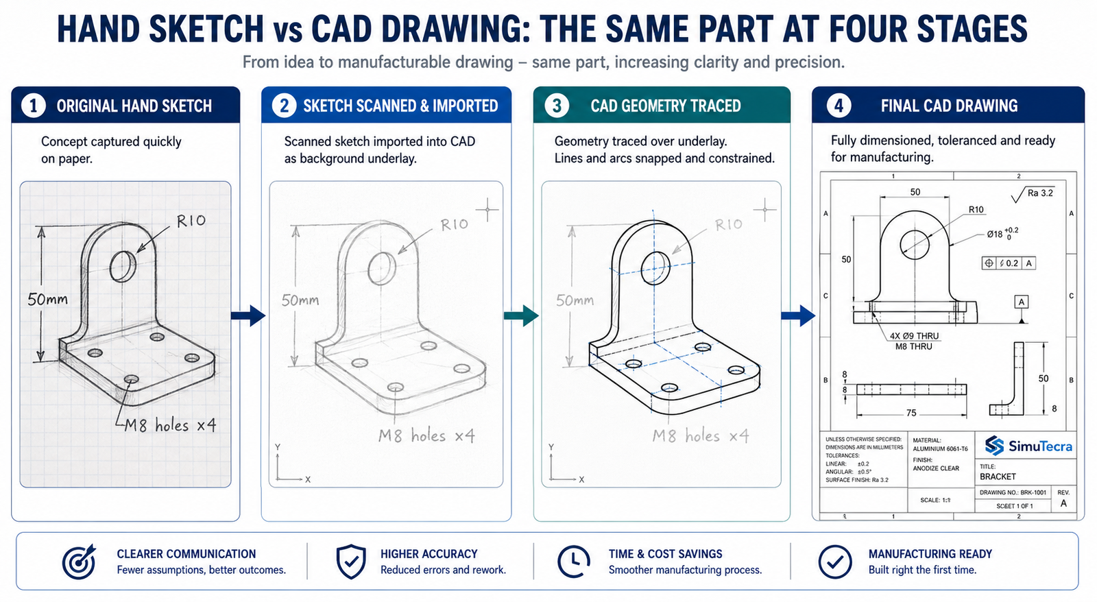
    Before any engineer opens CAD software, before any parametric model is built, before any drawing is dimensioned, there is usually a sketch. On the back of an envelope, on a whiteboard, on graph paper in a site meeting, on a napkin at a client conversation. The sketch is where the design intent lives in its earliest, most honest form.

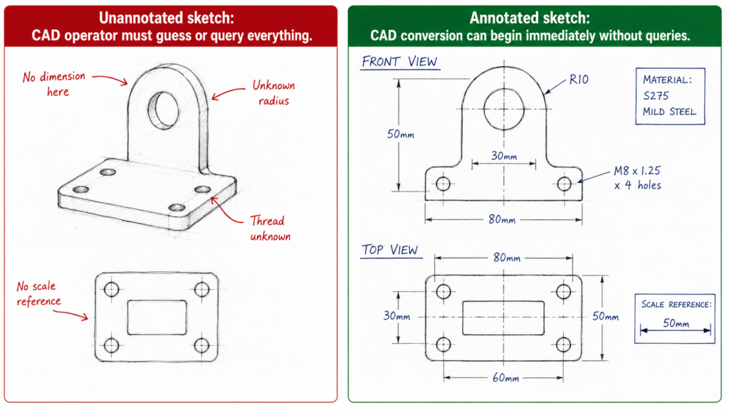
    The challenge is that a sketch, no matter how clear to the person who drew it, is not a manufacturing instruction. It has no scale guarantee, no tolerance definition, no projection convention, no standard symbol for surface finish or weld specification. A fabricator or machinist working from a hand sketch is working from engineering intent without the engineering rigour that turns that intent into a part.

    Converting a hand drawn sketch to CAD is the process that bridges that gap. It is not simply tracing lines. It is a structured engineering activity that takes the intent captured in the sketch and translates it into a document that carries enough information for a manufacturer to build the part correctly without needing to contact the engineer for clarification.

    This guide covers the complete workflow for sketch to CAD conversion, from preparing the sketch before scanning to issuing the final drawing for manufacturing. It also covers where AI tools genuinely help in 2026, where they do not, and the mistakes that produce wrong geometry at every stage of the process.

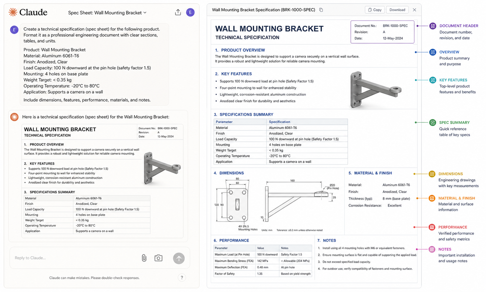
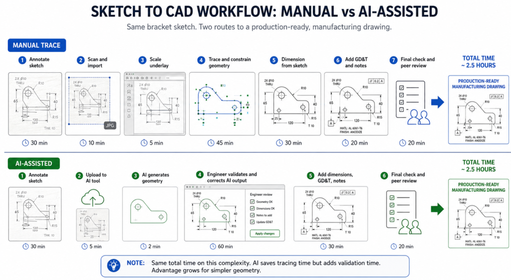
    Quick answer:  To convert a hand-drawn sketch into a CAD drawing: annotate the sketch with all critical dimensions before scanning, scan at 600 DPI minimum, import as a scaled underlay in your CAD software, trace geometry with geometric constraints applied, add dimensions from the sketch annotations, apply GD&T and manufacturing specifications, verify against the original sketch, and peer-review before issue. AI tools can assist with concept geometry but cannot yet produce manufacturing-ready drawings without engineering validation.
    How to Convert Hand-Drawn Sketches into Professional CAD Drawings  Sketch to CAD
    The sketch is the idea. The CAD drawing is the instruction. The conversion is an engineering activity, not a drawing exercise.

    Choosing Your Conversion Approach: Five Methods and When to Use Each

    Before starting any CAD drawing from sketch work, the most important decision is which conversion method is appropriate for the output required. The method determines how much time the conversion takes, what quality of output it produces, and whether that output is suitable for its intended use.

    ApproachWhat It InvolvesBest When
    Manual trace (2D CAD)Engineer imports scanned sketch as underlay, traces lines manually, applies dimensionsSketch is complex, requires GD&T, or is destined for a manufacturing drawing package
    AI-assisted sketch conversionUpload sketch to AI tool; AI generates geometry; engineer validates and refinesSimple geometry, concept visualisation, or getting a 3D starting point quickly
    AutoCAD Markup ImportImport scanned or PDF sketch; AutoCAD interprets marks and suggests geometryExisting AutoCAD workflow; sketch is relatively clean and line-based
    Photogrammetry + CADPhotograph physical object or model; import into CAD as reference mesh or point cloudPart physically exists but no drawing exists; RE workflow supplements sketch
    Outsourced sketch-to-CADProvide annotated sketch to a CAD specialist; they produce the drawingTeam lacks CAD capability; volume of conversions is high; deadline is tight

    The Honest Reality About AI Sketch Conversion in 2026

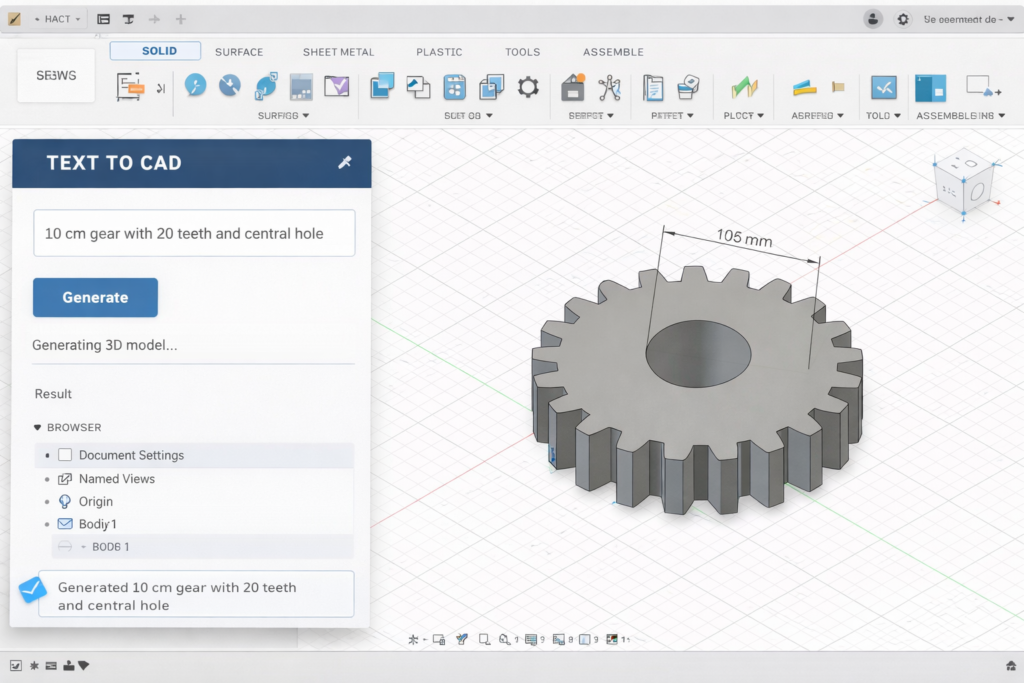
    The AI sketch-to-CAD landscape in 2026 is significantly more active than it was two years ago. Ragnar CAD, launched in February 2026, describes itself as purpose-built to close the gap between seeing an idea and modeling it. AutoCAD Markup Import has been present since the 2023 release and handles line-based sketches reasonably well. Autodesk Raster Design converts scanned images to editable vector geometry in AutoCAD.

    However, when Xometry, a major manufacturing marketplace, tested seven text-to-CAD and sketch-to-CAD tools in August 2025, the findings were consistent: all tools produced geometry that required significant engineering refinement before it could be used for manufacturing. The AI is interpreting visual patterns, not engineering intent. It does not know that a circle represents a through-hole of a specific standard size. It does not apply geometric constraints that would make two lines parallel. It does not understand that a tangent transition must be mathematically smooth.

    This does not make AI tools useless. For concept geometry, early-stage visualisation, and getting a 3D starting point from an annotated sketch, tools like Ragnar CAD can save meaningful time. But the output requires validation, refinement, and the addition of all manufacturing information before it can be used as a production drawing. The engineer remains responsible for every dimension that appears on the final drawing, regardless of how it was generated.

    AI sketch conversion red flag:  Any tool that claims to convert a hand sketch directly to a manufacturing-ready DWG or STEP file without engineering input is making a claim that current technology cannot support. A sketch has no tolerances, no GD&T, no datum structure, and no manufacturing specifications. None of these can be inferred from sketch geometry alone. They must be added by an engineer. The AI handles geometry interpretation. The engineer handles engineering.

    Preparing Your Sketch for CAD Conversion: The Step Most People Skip

    The quality of the CAD drawing you produce is determined before you open the software. A sketch that is fully annotated, clearly drawn, and systematically organised converts quickly and accurately. A sketch that is vague, proportionally distorted, and missing dimensions forces the CAD operator, whether that is you or an outsourcing partner, to make engineering decisions that should have been made by the designer.

    The time spent annotating the sketch thoroughly before scanning pays back immediately in the conversion process and many times over if the drawing is being produced by a CAD specialist. Every query raised during conversion, every dimension that must be estimated rather than read, adds cost and delay and risks introducing errors that the original sketch did not contain.

    Sketch ElementWhat Makes It CAD-ReadyWhat Causes Problems at the CAD Stage
    Line clarityBold, continuous lines; no broken strokesFaint pencil lines that digitise as noise; overlapping smudged strokes
    Dimension annotationsAll critical dimensions written clearly next to featuresMissing dimensions force CAD operator to guess or query; incorrect output guaranteed
    ProportionsSketch roughly to scale; major features proportionally correctWildly distorted proportions make the CAD baseline incorrect before any refinement
    Feature identificationEach feature clearly bounded; circles closed; arcs labelled as arcsAmbiguous lines that could be a tangency, a step, or a gap produce wrong geometry
    Orthographic viewsFront, top, and side views clearly labelled and positionedMissing view or mislabelled projection produces 3D model with features on wrong faces
    Reference planesCentre lines, axis of symmetry, and datum planes markedNo reference planes forces CAD operator to assume datum structure; may be wrong
    Notes and calloutsMaterial, finish, special requirements noted on the sketchUndocumented requirements surface after CAD is complete; rework cycle begins
    Scale referenceOne known dimension or scale bar presentNo scale reference means AI tools guess proportions; manual trace loses context

    The Annotation Checklist: What to Add Before You Scan

    1. All critical dimensions written in pen next to every feature. Length, width, height, hole diameter, radius, depth, thread specification. Not ‘approximately 50mm’. Exactly 50mm or the correct tolerance range.
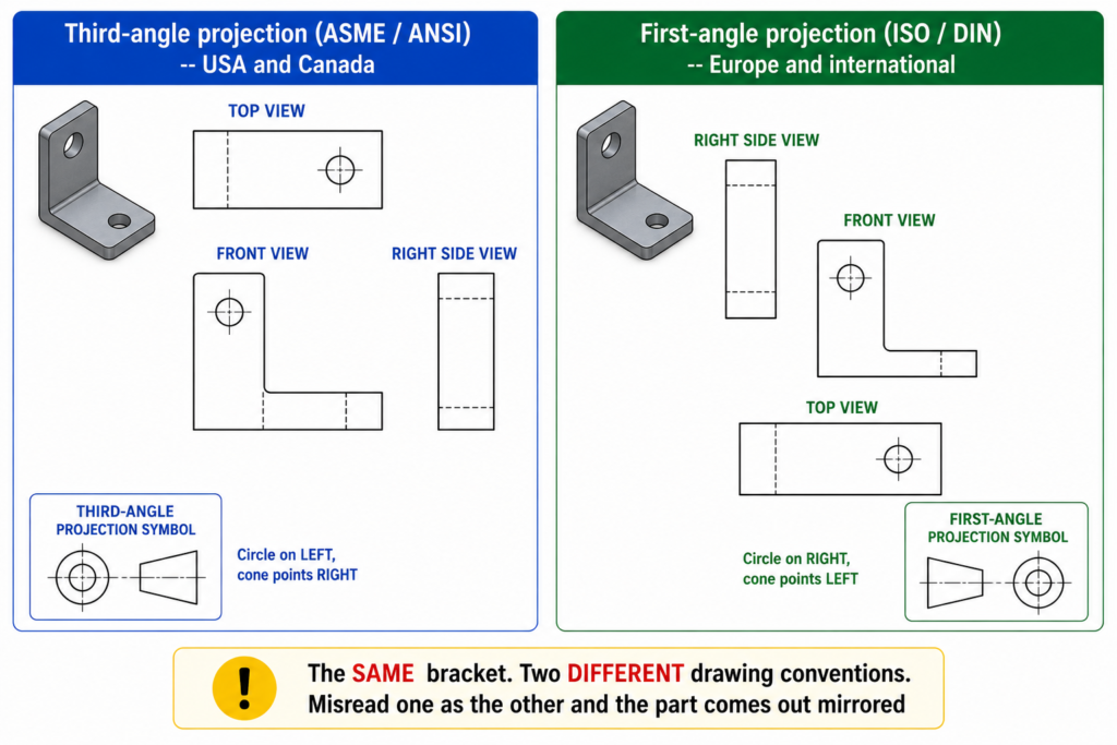
    2. Orthographic view labels. Write ‘FRONT VIEW’, ‘TOP VIEW’, ‘RIGHT SIDE VIEW’ clearly next to each view. Label the projection method if you know it (first-angle or third-angle).
    3. Centre lines and axes of symmetry drawn as thin lines with alternating long-short dashes, or simply labelled ‘CL’ or ‘SYM’. These define the datum structure that the CAD model must reference.
    4. At least one scale reference. Either a dimensioned scale bar or one known dimension from which everything else can be scaled. Without this, the CAD operator has no way to set the underlay at the correct scale.
    5. Material and surface finish notes. Write the material grade and any surface finish requirement directly on the sketch. Add thread standards where relevant (M12x1.75, 1/2-13 UNC).
    6. Special requirements and constraints. If a feature must be concentric with another, write it. If a surface must be flat within a stated tolerance, note it. If there is a mating part, sketch the mating geometry or note the mating part number.
    The pre-scan annotation habit:  Treat the annotation step as a design review of your own sketch. If you cannot write a dimension next to a feature because you do not yet know what the dimension should be, the design is not ready for CAD conversion. The sketch annotation step forces every engineering decision to be made before the drawing production starts, which is exactly when those decisions cost the least to change.

    Step-by-Step: Converting a Hand Sketch to a CAD Drawing

    This is the complete workflow for converting a hand-drawn sketch into a professional CAD drawing in AutoCAD or SolidWorks. The same sequence applies for most CAD platforms. The tool names vary but the logic is the same.

    Sketch to Cad Annotated vs Unannotated sketch
    The annotation is not extra work. It is the engineering work. The CAD conversion is just the documentation
    StepWhat HappensKey Action RequiredCommon Error at This Step
    1. PrepareAnnotate sketch fully before scanningAdd all dimensions, labels, and reference marks to the physical sketchScanning first then trying to add annotation to the digital image
    2. Scan / photographCreate a clean digital image of the sketch600 DPI minimum for scanning; good lighting for photography; no distortionLow-resolution scan; angled photograph; shadow across sketch
    3. Import underlayBring the image into CAD as a reference underlayScale the underlay using a known dimension (INSUNITS + reference scale)Importing without scaling; drawing on top of wrong-scale reference
    4. Set up drawingConfigure units, projection method, layers, and templateUse company drawing template before creating any geometryStarting on Layer 0 with no template; default settings applied
    5. Trace 2D geometryDraw CAD lines and arcs over the underlayUse constraints to make geometry geometrically correct, not just visually closeTracing visually without applying geometric constraints; drawing remains unconstrained
    6. Apply dimensionsDimension every feature required for manufactureCheck every dimension against the sketch annotation; query anything unclearScaling dimensions from the underlay instead of reading the sketch annotation
    7. Add GD&TApply tolerances, datum structure, and surface finish calloutsUse the drawing standard appropriate to the manufacturing destinationSkipping GD&T entirely and relying on general tolerance for everything
    8. Add 3D modelExtrude or revolve 2D profile to create 3D solid if requiredVerify every sketch profile is a closed loop before 3D operationOpen profiles that prevent extrusion; missing fillet or chamfer detail
    9. Final checkOverlay CAD drawing on original sketch to verify correspondenceEvery feature in the sketch should be present in the CAD; every dimension should matchMissing features; dimensions that do not match the annotated sketch values
    10. IssueRelease drawing through normal review and approval processPeer review against the drawing standard; title block completeIssuing without peer review; reverting to the sketch as the production reference

    Step 1 to 3: Preparing and Importing the Sketch

    The first three steps happen before you draw a single CAD line. Sketch annotation ensures every engineering decision is made before conversion starts. Scanning at 600 DPI minimum produces an image with enough resolution for clean line recognition, whether you are tracing manually or using an AI assist tool. Anything below 400 DPI produces a raster image where sketch lines are broken or blurred at the edges, making accurate tracing significantly harder.

    Scaling the underlay correctly is the most technically critical step in the import process. The INSUNITS system variable in AutoCAD controls how the software interprets the scale of inserted content. If INSUNITS is set to millimetres and you import an image scanned at 96 DPI (standard screen resolution), the image will import at screen-pixel scale, not millimetre scale. Use the SCALE command with the reference option immediately after import: select the underlay, pick two points at either end of a known dimension on the sketch, and type the known dimension value. The software scales the underlay so that dimension matches exactly.

    Step 4 to 6: Setting Up, Tracing, and Dimensioning

    Setting up the drawing before tracing is not optional. Tracing on Layer 0 without a template is the single most common error in sketch-to-CAD conversion work. Layer 0 geometry cannot be managed by layer, cannot have line weights assigned correctly, and creates a drawing that does not meet any professional drawing standard. Open your company template file or create a new drawing with the correct layer structure, then import the underlay into that environment.

    When tracing, work with geometric constraints active. Every relationship visible in the sketch that should be geometric, not just visual, must be applied as a constraint. Two lines that look parallel are not necessarily parallel until a parallel constraint is applied. A circle that appears tangent to a line may not be until a tangent constraint is set. Geometry that is visually approximate but not mathematically constrained produces a drawing that cannot be used reliably for manufacturing because the relationships it shows are not guaranteed to hold.

    Dimensioning from the sketch annotation, not from the underlay geometry, is the rule that prevents scale errors from propagating into the drawing. The underlay is a reference image. Its geometric proportions may be accurate or may not, depending on how the original sketch was drawn. The annotations on the sketch are the engineering values. Always type the annotated value into the dimension, not the measured distance from the underlay.

    Step 7 to 10: GD&T, 3D, Checking, and Issue

    Adding GD&T from a sketch is a translation exercise. The sketch may show a circle with a note ‘concentric with boss’. The CAD drawing translates that into a position tolerance referenced to the appropriate datum axis. The sketch may show a surface with a note ‘flat, smooth surface’. The CAD drawing translates that into a flatness tolerance and an Ra surface finish callout. The sketch provides the design intent. The CAD drawing provides the engineering specification.

    For 3D modeling from a sketch, the critical check is profile closure. Every 2D sketch profile that will be extruded, revolved, or used as a sweep path must be a closed loop with no gaps, overlaps, or branching lines. In SolidWorks, use the Sketch Doctor tool before any 3D operation to identify open contours. In Fusion 360, the extrude command will warn if the profile is not closed. In AutoCAD, the BOUNDARY command helps identify closed regions from traced geometry.

    The final check is the overlay: place the completed CAD drawing alongside the original sketch and compare every feature. Every view that existed in the sketch should exist in the CAD drawing. Every dimension that was annotated on the sketch should appear on the CAD drawing with the correct value. Any feature present in the sketch that is absent from the CAD drawing is a missing element that must be added before issue.

    Using AutoCAD Markup Import for Sketch Conversion

    AutoCAD Markup Import, introduced in AutoCAD 2023 and developed further in subsequent releases, is Autodesk’s built-in tool for converting scanned drawings and markups into editable CAD geometry. It handles the most common use case for sketch to AutoCAD conversion: a sketch or marked-up drawing on paper, scanned to PDF or image, that needs to become editable DWG geometry.

    How Markup Import Works

    The workflow: import the scanned image or PDF markup into AutoCAD, which places it as a background reference. Markup Import’s AI analyses the image and identifies lines, arcs, circles, and text. It then overlays suggested geometry on the image, which the engineer accepts, rejects, or modifies. Accepted geometry becomes editable AutoCAD objects on specified layers.

    The tool is genuinely useful for drawings with clear, clean lines, straight edges, and simple geometry. It struggles with freehand curves, overlapping lines, and complex connection points. It does not interpret engineering intent: a circle with four lines radiating from it at 90-degree intervals might be a bolt circle pattern, a wheel, a connection diagram, or a structural element. Markup Import will create a circle and four lines. Deciding what they mean is an engineering judgment that the tool does not make.

    Autodesk Raster Design: The More Powerful Alternative

    For organisations with more demanding raster-to-vector conversion requirements, Autodesk Raster Design (a free add-on for AutoCAD subscribers) provides more comprehensive raster image processing. It cleans image noise, straightens lines, converts raster arcs to vector arcs, and handles complex legacy drawing conversion more reliably than Markup Import alone.

    Raster Design is particularly useful for converting large volumes of legacy scanned drawings to editable CAD, a common requirement in industries that have paper drawing archives from pre-CAD decades. For converting fresh hand sketches, Markup Import is usually sufficient.

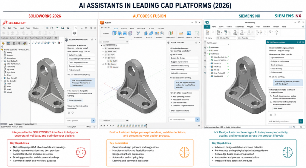
    AI Sketch-to-CAD Tools: What Actually Works in 2026

    The AI sketch to CAD market in 2026 is loud and active. New tools appear regularly with significant marketing claims. The honest engineering assessment is that all current tools sit somewhere on the spectrum between ‘useful starting point for concept geometry’ and ‘requires complete engineering rebuild before manufacturing use’. None sits at ‘production-ready manufacturing drawing from sketch without engineering input’.

    ToolTypeWhat It Actually DoesBest Realistic Use CaseHonest Limitation
    Ragnar CADSketch-to-3D AIInterprets sketch geometry; generates 3D mesh or solidConcept geometry from annotated sketchOutput needs significant refinement for manufacturing use
    AutoCAD Markup ImportDrawing importRecognises lines and shapes in scanned markup; suggests CAD geometryUpgrading scanned 2D drawings to editable DWGDoes not understand engineering intent; produces dumb geometry
    Autodesk Raster DesignRaster-to-vectorConverts scanned raster image to vector lines in AutoCADExisting AutoCAD workflow with scan inputManual cleanup of noise and artefacts still required
    Leo AIEngineering AISearches existing CAD vault; assists with design intent; not sketch-to-CADFinding similar existing parts; reuse of previous designsNot a sketch conversion tool; often mispositioned in marketing
    Pixa / similarAI image-to-visualGenerates technical-style visual from sketch imageVisualisation and presentation imagesNot a CAD file; not manufacturable; not dimensioned
    SketchUpManual 3D modelingSimple push-pull 3D from 2D sketch input; not AI-drivenArchitecture concept models from floor plan sketchNo engineering GD&T capability; not suitable for manufacturing
    Traditional tracingManual CADEngineer manually traces sketch in AutoCAD or SolidWorksAny application requiring a production-ready drawingSlowest method; most reliable for manufacturing output

    The Xometry Test Results: What the Data Actually Shows

    When Xometry tested seven AI sketch and text-to-CAD tools in August 2025, the findings were consistent across all tools: simple prismatic geometry was handled reasonably; complex geometry with multiple interacting features was inconsistent; none produced output with tolerances, GD&T, or manufacturing specifications; all required significant engineering review and refinement.

    This is not a criticism of the tools. It reflects the fundamental challenge: interpreting sketch geometry is a different problem from understanding engineering intent. A sketch line that represents a wall might be 2mm thick, 20mm thick, or structural steel. The sketch looks the same. The engineering specification does not. Until AI tools can reliably infer engineering intent from visual sketch input, the engineer remains essential to every sketch-to-CAD workflow that produces a manufacturing deliverable.

    Where AI Sketch Tools Add Genuine Value

    • Concept geometry for client presentations. Getting a rough 3D view of a concept in minutes rather than days. The geometry does not need to be manufacturing-ready.
    • Starting point acceleration. A reasonable first-pass geometry from Ragnar CAD or Markup Import gives the engineer a starting model to refine rather than building from a blank file.
    • Legacy drawing digitisation at volume. Converting hundreds of scanned paper drawings to editable DWG where speed matters more than perfection on each individual drawing.
    • Rapid iteration on proportions. Testing multiple layout interpretations of the same sketch quickly before committing to detailed CAD work.
    Sketch to CAD Workflow: Manual vs AI-Assisted Side-by-Side Timeline
    AI tools accelerate the geometry step. The engineering steps remain the same.

    Working in SolidWorks: Converting a Sketch to a Parametric 3D Model

    When the end deliverable is a 3D parametric model rather than a 2D drawing, SolidWorks (or Creo, Inventor, or Fusion 360) is the appropriate tool. The workflow differs from AutoCAD in a fundamental way: instead of tracing the sketch as a 2D drawing, you trace it as a 2D sketch profile inside SolidWorks that will then be extruded, revolved, or used as a path sweep to create the 3D solid.

    The SolidWorks Sketch Import Workflow

    1. Create a new part document using your company SolidWorks template.
    2. Insert the scanned sketch as a sketch picture on the front plane or the plane most representative of the primary view in the sketch.
    3. Scale the sketch picture by dragging the scale handle or entering a scale factor. Use the same reference dimension method: identify a known dimension on the sketch and scale until the measured distance in SolidWorks matches the annotated value.
    4. Trace the 2D profile over the sketch picture using sketch tools. Apply all geometric constraints. Every relationship in the sketch that should be mathematical must be a constraint, not an approximation.
    5. Verify closure before any 3D operation. Use Sketch Doctor or the profile highlighting that appears when you hover over the Extrude feature to confirm the sketch is fully closed.
    6. Apply driving dimensions from the sketch annotations. Make the sketch fully defined before extruding.
    7. Extrude or revolve to create the 3D body. Delete or hide the sketch picture underlay after the 3D model is complete.
    8. Create the 2D drawing from the 3D model using SolidWorks Drawing. The drawing views are generated from the model, ensuring the drawing and model are always consistent.

    Why SolidWorks Produces a More Complete Output

    The SolidWorks workflow produces two deliverables from one sketch: a parametric 3D model and a manufacturing drawing derived from that model. The drawing and model are linked: change the dimension in the drawing and the model updates; change the model and the drawing views update. This is significantly more valuable than a 2D AutoCAD drawing alone for parts that will be revised, analysed, or used as the basis for a part family.

    For straightforward 2D applications (construction drawings, civil layouts, P&IDs, structural floor plans) AutoCAD is the more efficient route. For mechanical part design that will go through multiple iterations, SolidWorks or an equivalent parametric 3D platform produces an output that serves the full product development lifecycle, not just the initial manufacturing order.

    Outsourcing Sketch-to-CAD Conversion: When and How

    Sketch-to-CAD conversion is one of the most commonly outsourced engineering drawing activities, and for good reason. It is a well-defined scope of work with a clear input (the annotated sketch) and a clear output (the CAD drawing), and it benefits from specialists who do this type of work repeatedly and efficiently.

    The conditions under which outsourcing sketch-to-CAD conversion makes sense: the volume of conversions is higher than in-house capacity can handle efficiently, the in-house team lacks CAD capability or CAD proficiency for the specific type of drawing required, the deadline is tighter than the in-house workflow can meet, or the drawing type (architectural floor plans, structural steel, MEP schematics) requires specialist CAD knowledge that the in-house team does not have.

    What to Give an Outsourcing Partner for Sketch Conversion

    • The annotated sketch: fully dimensioned, labelled, with material and finish notes, and at least one scale reference. If the sketch is inadequately annotated, the partner will query or guess. Both add cost and risk.
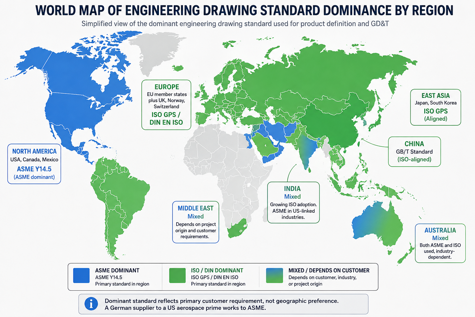
    • The drawing specification: your drawing standard (ASME Y14.5 or ISO 1101), CAD software and version, file format required, layer naming convention, and title block template. Without these, the partner produces a technically competent drawing in their own style, not yours.
    • Go-by drawings: two or three representative drawings from your existing archive that show your exact style, layer structure, line weights, and annotation conventions. A written specification and a visual example together eliminate virtually all style-related rework.
    • A clear brief of any constraints not visible in the sketch: mating part requirements, assembly context, functional requirements that affect manufacturing priority. The sketch shows geometry. The brief provides the engineering context that the sketch cannot communicate.

    Common Mistakes in Sketch-to-CAD Conversion

    These are the errors that most consistently produce wrong output from sketch to CAD conversion, whether the work is done in-house or by an outsourcing partner.

    MistakeWhat Goes WrongPrevention
    Scanning sketch before annotating itDigital image has no dimensions; guessing from proportions throughoutComplete all annotations on the physical sketch before scanning. Scanning is the last step in sketch preparation.
    Importing at wrong scale (INSUNITS mismatch)All traced geometry is at the wrong scale; dimensions incorrectSet INSUNITS before import. Scale the underlay using one known dimension immediately after import.
    Tracing visually without geometric constraintsLines appear parallel but are not; circles appear tangent but are notApply constraints (parallel, perpendicular, tangent, concentric) to every geometric relationship in every sketch.
    Using scale from underlay for dimensionsDimensions reflect the scan proportions, not the design intentAlways read dimensions from the sketch annotation. Never scale from the underlay image.
    Treating AI-generated geometry as production-readyMesh or approximated geometry sent to manufacturer; parts cannot be madeAI tools produce starting points. Every AI output requires engineering validation before manufacturing release.
    Skipping the 3D profile closure checkExtrude fails or creates wrong solid because sketch profile is not closedCheck every sketch profile for closure before any 3D operation. Use the profile analysis tool before extruding.
    No peer review before issueDrawing released with errors that a second set of eyes would have caughtApply the pre-release checklist. Require a second engineer to sign off before any drawing is issued from a sketch.
    Losing the original sketch after CAD is completeConflict between sketch intent and CAD output cannot be resolvedArchive the annotated sketch alongside the CAD file as a permanent project record.
    The final overlay check:  The single most effective quality check in any sketch-to-CAD workflow is placing the finished CAD drawing alongside the original annotated sketch and comparing them feature by feature. Every view present in the sketch should be present in the CAD. Every annotated dimension should appear in the CAD with the correct value. Every note should be accounted for. This check takes five minutes and catches the majority of conversion errors before the drawing is issued.

    Conclusion:

    A hand-drawn sketch is the most natural form of engineering communication. It is fast, flexible, and honest. It captures proportions, relationships, and intent in a way that talking around a table cannot. But it is not an engineering instruction. It is the raw material that an engineering drawing is made from.

    The process of converting a hand drawn sketch to CAD is the process of translating that raw material into a precise, complete, and unambiguous manufacturing instruction. It requires engineering judgment at every step: which tolerances apply, which GD&T controls are needed, which dimensions govern assembly, and which features are critical versus general. These judgments cannot be made by tracing lines. They cannot be made by AI tools in 2026. They are made by the engineer who understood what the sketch was trying to say.

    AI tools are genuinely useful for concept geometry, for getting a 3D starting point from an annotated sketch, and for converting large volumes of legacy scanned drawings. They are not yet useful for producing manufacturing-ready engineering drawings from sketches without engineering validation. The tools are evolving quickly. The engineering requirement remains constant.

    Annotate the sketch fully. Import it correctly. Trace with constraints. Dimension from the sketch, not the underlay. Verify against the original. Then issue.

    Frequently Asked Questions

    How do you convert a hand-drawn sketch into a CAD drawing?

    To convert a hand-drawn sketch into a CAD drawing, follow this sequence: annotate the sketch with all critical dimensions, notes, and labels before scanning; scan at a minimum of 600 DPI or photograph with good even lighting; import the image into your CAD software as an underlay; scale the underlay using a known reference dimension; set up your drawing template with correct units, layers, and projection method; trace the geometry over the underlay and apply geometric constraints to all relationships; add dimensions, GD&T, surface finish, and material callouts; verify the CAD output against the original sketch by overlaying; and peer-review before issuing the drawing for manufacturing.

    Can AI tools convert a hand-drawn sketch to a CAD file automatically?

    AI tools can interpret sketch geometry and generate a starting point for a CAD model, but they cannot currently produce manufacturing-ready drawings from sketches without significant engineering input. When Xometry tested seven text-to-CAD tools in August 2025, all required substantial refinement for engineering use. Tools like Ragnar CAD (February 2026) and AutoCAD Markup Import can accelerate the process for simple geometry. For production drawings requiring GD&T, tolerances, and manufacturing specifications, human engineering validation remains essential regardless of which AI tool is used.

    What makes a hand-drawn sketch ready to convert to CAD?

    A hand-drawn sketch is ready to convert to CAD when it includes: all critical dimensions written clearly next to every feature, orthographic views labelled by name (front, top, side), centre lines and axes of symmetry marked, a scale reference or at least one known dimension, all feature boundaries clearly closed with no ambiguous lines, material and surface finish notes where relevant, and any special requirements or constraints annotated on the drawing. A sketch without dimensions is not a CAD input. It is a visual concept that requires engineering decisions before CAD work can begin.

    What is the difference between tracing a sketch in CAD and using AI conversion?

    Manual tracing in CAD involves importing the sketch as an underlay, drawing lines and arcs over it with geometric constraints applied, dimensioning every feature from the sketch annotations, and adding GD&T and manufacturing specifications. The result is an engineering drawing with full design intent. AI conversion interprets sketch geometry automatically and generates geometry without manual input. It is faster for simple shapes but produces approximate geometry without constraints, tolerances, or manufacturing specifications. Manual tracing is required for any drawing that will be used for manufacturing. AI conversion is useful for concept visualisation and early-stage geometry.

    How do I scale a hand-drawn sketch correctly in AutoCAD?

    To scale a hand-drawn sketch correctly in AutoCAD: first set the INSUNITS variable to match the unit system of your drawing before importing the image. Import the scanned image using the IMAGEATTACH command. Identify one dimension on the sketch where you know the exact real-world value. Use the SCALE command with the reference option to scale the image so that the known dimension matches its correct value in the drawing. Once the underlay is correctly scaled, all traced geometry will automatically be at the correct scale provided your INSUNITS setting is correct.

    Should I use AutoCAD or SolidWorks to convert a sketch to CAD?

    The choice between AutoCAD and SolidWorks depends on the output required. For 2D manufacturing drawings, construction drawings, or any application where a flat drawing set is the deliverable, AutoCAD is the more efficient tool. The underlay workflow is well-established and the 2D output is directly usable. For parts that require a 3D parametric model, assembly checking, FEA, or a manufacturing drawing derived from a 3D model, SolidWorks is more appropriate. The sketch becomes the reference for a 2D sketch profile in SolidWorks, which is then extruded or revolved to create the solid body. For most engineering manufacturing applications, SolidWorks produces a more complete and useful output from a hand sketch.


    ‘Autodesk: how AutoCAD Markup Import converts scanned drawings and sketches to editable geometry

  • How AI Is Changing Engineering Design: Real vs Hype 2026

    How AI Is Changing Engineering Design: Real vs Hype 2026

    A few years ago, the engineering software industry seemed to reach a collective agreement: AI was going to change everything. Vendors rewrote their marketing pages. Conference keynotes promised autonomous design systems that would shrink development cycles from months to days. Engineering managers were told to prepare for transformation.

    It is now 2026, and the honest assessment is more nuanced than the pitch decks suggested. Some of what was promised is genuinely here, deployed in real workflows at real companies, producing real time and cost savings. A meaningful part of it is still vendor theater: capable in demos, limited in production, and often solving the wrong problems.

    This article is written for engineers, engineering managers, and technical decision-makers who want a clear-eyed view of what AI is actually doing in engineering design today. Not what it might do by 2030. Not what a simulated benchmark shows. What is working right now, what is not, and what you should actually be paying attention to in your organization this year.

    We draw on the SimScale 2026 State of Engineering AI Report, Autodesk’s State of Design and Make survey, Gartner’s 2025 hype cycle analysis, firsthand feedback from engineers, and published research to give you a ground-level view of the current state of the art.

    Engineer reviewing AI-generated topology-optimized component in CAD software, illustrating the human-AI collaboration model in 2026 engineering design

    1. The State of AI in Engineering Design: 2026 at a Glance

    Before separating real from hype, you need a baseline picture of where the industry actually stands.

    MetricData PointSource
    Organizations using AI in at least one business function88%McKinsey / Intuit survey, 2026
    AEC firms that have formally adopted AI27%ASCE survey, late 2025
    AEC AI adopters planning to expand usage in 202694%ASCE survey, late 2025
    Engineering teams using AI generating design variants per program~4x more than non-AI teamsSimScale 2026 State of Engineering AI Report
    Simulation request speed-up for AI-enabled engineering workflows2.8x faster than conventionalSimScale 2026 Report
    Top barrier to scaling AI in engineeringData preparation and availability (74%)SimScale 2026 Report
    Organizations getting measurable ROI from AI projects (2025 MIT study)5% (95% report zero ROI)MIT NANDA GenAI Divide Report, 2025
    Digital twin market projected value by 2030$150 billion (from $21B in 2025)Industry analyst consensus

    These numbers tell a revealing story. Adoption is accelerating, particularly in engineering-heavy industries. But the gap between organizations that have installed AI tools and those generating measurable business impact from them remains enormous. The 95 percent figure from MIT’s NANDA report deserves direct acknowledgment: most AI projects in enterprise settings have not yet produced return on investment. That does not mean AI is failing. It means most organizations have not yet done the hard work of integrating AI meaningfully into real workflows.

    The engineering firms and manufacturing organizations that are generating impact share a common pattern, noted in the SimScale report: they are embedding AI into core engineering workflows rather than running it as a parallel experiment. The ones still running AI ‘pilots’ are, in most cases, not generating results.

    2. Understanding the Hype Cycle: Where Engineering AI Sits Right Now

    Gartner’s 2025 Hype Cycle for AI is instructive. Generative AI, after dominating the Peak of Inflated Expectations in 2023 and 2024, is now beginning its descent toward the Trough of Disillusionment. This is not a disaster. It is a normal and healthy maturation. The technologies that survive the trough, and most of the genuinely useful ones do, emerge on the slope of enlightenment as practical, well-understood tools that deliver consistent value.

    For engineering specifically, Autodesk’s State of Design and Make 2025 report found a meaningful drop in positive AI sentiment compared to the prior year. Fumihiro Ojima, general manager of digital innovation at Tokyu Construction, captured the shift clearly when he said the industry has come to understand that AI is suited to some things and not others, and that the initial impression of AI being able to do everything has passed.

    That recalibration is healthy for the engineering profession. It creates space for a more honest question: not ‘what can AI do eventually?’ but ‘what is AI reliably doing right now in engineering workflows, and what should I actually invest in?’

     DATA:  Gartner Trough Finding. Generative AI moved from Peak of Inflated Expectations toward Trough of Disillusionment in 2025. Technologies entering the trough typically reach practical productivity 2 to 5 years after initial peak hype.

    3. What Is Actually Working: AI Applications Delivering Measurable Value

    Let us be direct. These are the areas where AI in engineering design is producing documented, repeatable, commercially meaningful results in 2026, not in lab conditions, and not in vendor demos.

    Simulation Acceleration

    This is arguably the most consequential real-world application of AI in engineering today. Traditional finite element analysis (FEA) and computational fluid dynamics (CFD) simulation runs are computationally expensive and slow. A complex thermal analysis might take 12 to 48 hours to run on conventional infrastructure. AI surrogate models, trained on prior simulation data, can approximate simulation results in minutes, sometimes seconds, at acceptable accuracy for early-stage design decisions.

    The SimScale 2026 report found that engineering teams using AI-enabled simulation workflows process requests 2.8 times faster on average than those using conventional workflows. More significantly, these teams test nearly four times as many design variants per program. That is not marginal improvement. That is a structural change in what is practically possible within a given development timeline.

     REAL:  Simulation surrogate models. AI-accelerated simulation is working in production environments now. Teams at aerospace and automotive companies are using it to explore design spaces that were previously computationally prohibitive.

    Automated Drawing Production

    Autodesk’s Fusion has shipped an Automated Drawings feature that auto-generates 2D engineering drawings from 3D models, with automatic view selection, dimension placement, and basic annotation. Since launch, millions of automated dimensions and constraints have been applied. Engineers using it describe the feature as having moved from experimental to genuinely useful for routine drawing production over the past 12 months.

    SolidWorks 2026 has introduced a Command Predictor (currently in beta) that anticipates the next modeling command based on session context, a Contextual Assistant that recommends workflow optimizations in real time, and a Fastener Recognition feature that identifies and mates hardware components automatically. These are not capabilities that transform the design process on their own, but they represent real, daily time savings in routine modeling work.

     REAL:  Automated drawing generation. Autodesk Fusion’s Automated Drawings and SolidWorks’ Sketch AutoConstrain are in daily production use at engineering firms globally. Real time savings, not just demo capabilities.

    Topology Optimization

    Topology optimization is the process of computationally determining the most efficient material distribution within a defined design space, given specified loads and constraints. This is not a new idea, but AI has meaningfully improved both the speed of optimization runs and the manufacturability of the resulting geometries.

    Aerospace and automotive applications have been the primary beneficiaries. Airbus famously used topology optimization to redesign a cabin bracket, reducing its mass by 45 percent while meeting the same structural performance requirements. That specific project predates current AI tools, but it established the value proposition. Current AI-enhanced topology optimization in tools like Autodesk Fusion’s Generative Design, Siemens NX, and Altair OptiStruct is producing similar results with significantly shorter compute times and better integration with manufacturing constraints.

     REAL:  Topology optimization. Working reliably for structural, thermal, and aerospace applications. Best results come from combining AI topology output with engineer-applied manufacturing feasibility judgment.

    Part Search and Design Reuse

    One of the less glamorous but high-impact AI applications in engineering is intelligent part search. Most engineering organizations maintain libraries of thousands of existing parts, but engineers routinely create new parts that are near-duplicates of ones that already exist because finding the right existing part is harder than building a new one. AI-powered geometry search (tools like Leo AI and integrated PDM search in Siemens Teamcenter and PTC Windchill) allows engineers to search by shape similarity rather than name or part number.

    This addresses a genuine bottleneck that generative design tools largely ignore. According to Leo AI’s 2026 analysis of the CAD workflow, the biggest time sink in engineering design is not generating new geometry from scratch. It is finding and reusing what already exists.

     REAL:  AI-powered part search. Geometry-based part retrieval is delivering measurable productivity gains in organizations with large existing CAD libraries. High ROI with relatively low implementation complexity.

    Predictive Maintenance in Manufacturing

    AI-driven predictive maintenance has moved firmly from pilot to operational deployment in manufacturing. Systems that analyze sensor data from production equipment to predict failure before it occurs are now standard infrastructure at large manufacturers in automotive, aerospace, and process industries.

    A 2025 research analysis of 1,094 manufacturing companies in Visegrad Group countries found that companies deploying predictive maintenance algorithms generated higher operational profits and lower sales costs relative to those using conventional maintenance approaches. A separate 2025 publication in the American Journal of Advanced Technology and Engineering Solutions reported that AI-driven predictive maintenance for electrical systems now reaches 85 to 95 percent accuracy in failure prediction.

     REAL:  Predictive maintenance. This is the most commercially mature AI application in engineering-adjacent domains. Production deployments with documented ROI exist across automotive, aerospace, energy, and process manufacturing.

    4. Generative Design: Genuine Breakthrough or Overhyped Feature?

    Generative design is the poster child of AI in engineering, and it deserves honest examination. The concept, that you define your design constraints (loads, materials, manufacturing methods, cost targets) and an AI generates multiple optimized geometry options that meet those constraints, is genuinely powerful. It is also genuinely limited in ways that vendor marketing does not advertise.

    Where Generative Design Delivers

    For well-defined, single-objective design problems with clear constraints, generative design works well. Structural components that must meet specific load cases with minimum weight, under manufacturing constraints like casting or CNC machining: this is the sweet spot. Autodesk’s generative design in Fusion, SolidWorks’ generative capabilities, and Altair OptiStruct have produced documented weight reductions and performance improvements in aerospace, automotive, and industrial applications.

    The SimScale report finding that AI-enabled engineering teams generate nearly four times as many design variants is substantially powered by generative design tools that can produce dozens of candidate geometries in the time it would take an engineer to produce one manually. That expanded design space exploration is real.

    Where Generative Design Falls Short

    The limitations are significant and are not often discussed in vendor materials. Dessia, a specialist in AI-based design engineering, published a direct 2026 analysis of what generative design still cannot do, and the list is instructive:

    • Multi-objective tradeoffs requiring human judgment: Generative algorithms can optimize for a stated objective. They cannot resolve unstated tradeoffs, manage competing stakeholder priorities, or understand that a design needs to be manufacturable by a specific supplier’s existing tooling, not just theoretically manufacturable in principle.
    • Context beyond the model: Generative design operates on the geometry and constraints you define. It has no awareness of supply chain realities, assembly ergonomics, serviceability requirements, cost of manufacturing change, or the political realities of getting a new design approved by a customer.
    • Selection and judgment: Generative design produces candidates. It does not select the right one. That decision requires engineering judgment that weighs factors the system cannot model. The bottleneck shifts from generation to evaluation, and evaluation is still a human job.
    • Novel design problems: AI-driven generative design is essentially extrapolating from patterns in training data and prior simulations. For genuinely novel engineering problems, outside the distribution of what the system has seen, the output quality degrades and engineer oversight becomes critical.
    HYPE:  Generative design as autonomous design tool. Generative design is a powerful computational tool. It is not an autonomous design system. The claim that it eliminates the need for experienced design engineers misrepresents what the technology actually does.

    5. AI in Simulation and Digital Twins: The Most Consequential Development

    If you want to identify the AI application in engineering with the greatest long-term structural impact, the combination of AI and digital twins is the leading candidate. And unlike many AI applications in engineering, this one has a solid foundation of peer-reviewed research, commercial deployment cases, and measurable outcomes.

    What a Digital Twin Actually Is (and Is Not)

    A digital twin is a continuously updated virtual model of a physical asset or system, connected to real-time data from sensors on the physical counterpart. The digital twin does not just represent the asset as-designed; it represents the asset as it actually exists and behaves in its current operational state. This is fundamentally different from a CAD model or a simulation model, both of which are static snapshots.

    The combination with AI adds the capability to run predictive models against the digital twin: predicting how the physical asset will behave under future conditions, identifying early signs of degradation before failure, and optimizing operational parameters in real time. Published research in Frontiers in Artificial Intelligence (December 2025) describes how this architecture enables real-time monitoring, predictive maintenance, and intelligent process optimization in manufacturing environments.

    Real Deployments and Outcomes

    Digital twin deployments are no longer confined to aerospace primes and automotive OEMs with unlimited R&D budgets. Cloud platforms from Siemens (Teamcenter X), PTC (ThingWorx), and Ansys (twin builder) have made digital twin infrastructure increasingly accessible to mid-size manufacturers.

    The Ansys 2026 R1 release, launched March 2026, introduces generative AI and the portfolio’s first agentic capabilities into simulation workflows. The release specifically addresses faster design exploration, validation earlier in development, and reduced reliance on physical testing. These are not theoretical roadmap items; they are shipping in the current product.

    In civil infrastructure, published 2026 research in Spectrum of Engineering Sciences documents digital twin deployments using AI-based structural performance modeling for predictive maintenance of bridges and buildings, integrating IoT sensor data with BIM models to create assets that self-monitor and flag deterioration before it becomes a structural risk.

    REAL:  AI-powered digital twins. This is the most technically mature and commercially deployed application of AI in engineering systems today. ROI cases exist across manufacturing, aerospace, energy, and civil infrastructure.

    Where Digital Twins Are Still Maturing

    The implementation complexity is substantial. Building a functioning digital twin requires clean, structured sensor data (74 percent of organizations in the SimScale study cite data preparation as their top AI scaling barrier), integration between IT and OT systems, ongoing model maintenance as the physical asset evolves, and cybersecurity infrastructure to protect what is essentially a real-time data connection to critical equipment.

    For organizations that have not yet built clean data infrastructure, the digital twin is not a starting point. It is a destination that requires significant foundational work first.

    6. AI Copilots in CAD: What the Major Platforms Are Actually Shipping

    Every major CAD platform now has an AI story. The critical question is whether the features being shipped are solving problems that engineers actually have in daily work, or whether they are impressive demos that engineers rarely reach for after the first week.

    Side-by-side comparison of AI assistant interfaces in SolidWorks 2026, Autodesk Fusion, and Siemens NX showing copilot and generative design features

    [IMAGE 2] Screenshot composite showing AI assistant interfaces from SolidWorks 2026, Autodesk Fusion, and Siemens NX side by side. Placement: After Section 6 intro paragraph. ALT: ‘Side-by-side comparison of AI assistant interfaces in SolidWorks 2026, Autodesk Fusion, and Siemens NX showing copilot and generative design features’

    CAD PlatformKey AI Features (2025-2026)What Is Working in PracticeHonest Limitation
    SolidWorks 2026 (Dassault)AURA design companion, Command Predictor (beta), Fastener Recognition, Contextual Assistant, Generative AssemblySketch AutoConstrain, Fastener Recognition, and Selection Accelerators are in daily use; real time savings on routine tasksAURA’s generative assembly is still beta; significant generation capabilities remain works-in-progress
    Autodesk FusionAutomated Drawings, Sketch AutoConstrain, Autodesk Assistant (GenAI copilot), Fusion MCP for third-party AI integration, Generative DesignAutomated Drawings widely adopted; millions of dimensions auto-generated; MCP integration with Claude for natural language design actionsGenerative Design valuable for constrained structural problems; limited for complex multi-discipline design
    Siemens NXAdaptive UI, AI Chat Copilot, AI-assisted meshing, generative design toolsChat Copilot reduces documentation lookup time; adaptive UI improves workflow discoveryFull workflow automation still requires significant setup; best results require experienced NX users directing the AI
    PTC Creo 12 / OnshapeAI-driven generative design with thermal physics integration, AI Advisor, Design Assistant, real-time Ansys simulation integrationOnshape AI Advisor useful for beginners; Creo’s generative design strong for mechanical-thermal combined optimizationComplex regulatory and standards compliance still manual; AI outputs require experienced engineer review
    Ansys 2026 R1Generative AI, first agentic capabilities, AI-enhanced simulation, digital twin integrationAI-accelerated simulation workflows delivering 2-3x speed improvement in benchmarks; agentic features in early accessFull agentic automation requires clean data infrastructure most organizations do not yet have

    The pattern across platforms is consistent. Features that accelerate routine, well-defined tasks (auto-dimensioning, fastener recognition, documentation lookup, view generation) are genuinely useful and widely adopted. Features that promise to generate complex designs from high-level intent are more constrained in practice than their marketing suggests and require experienced engineers to evaluate, filter, and refine their outputs before anything is usable.

    Leo AI’s 2026 analysis of the CAD tool landscape makes this point precisely: most AI CAD tools in 2026 solve problems engineers do not actually have, while leaving the painful ones untouched. Documentation chatbots, for instance, primarily help new users find commands. Experienced engineers already know the commands. The bottleneck they face is workflow context and institutional knowledge, not documentation lookup.

    7. Predictive Maintenance and AI in Manufacturing: Real Outcomes, Honest Limitations

    The Clear Successes

    AI-driven predictive maintenance is the commercial success story of AI in engineering-adjacent domains. The application is well-suited to AI: large volumes of structured sensor data, clear ground truth labels (a machine either failed or it did not), and high economic value in predicting failure before it occurs.

    Published research now consistently demonstrates prediction accuracy of 85 to 95 percent for failure events in electrical and mechanical systems. Industry deployments at automotive manufacturers, energy companies, and aerospace maintenance organizations have documented reductions in unplanned downtime of 30 to 50 percent, with corresponding maintenance cost reductions.

    What Makes Predictive Maintenance Different from Other AI Applications

    Predictive maintenance works in practice where many other AI engineering applications struggle because the problem is well-structured. The data is digital (sensor readings), the label is binary (failure/no failure), the business case is directly quantifiable (cost of downtime), and the human oversight model is clear (the AI flags, the maintenance engineer decides). This combination of clear problem definition, clean training data, and a well-designed human-in-the-loop process is the template for AI engineering applications that actually deliver ROI.

    Honest Limitations

    Not every manufacturing environment has the sensor infrastructure to make predictive maintenance viable. Older equipment may lack the connectivity to generate the data the models need. Environments with significant process variability can degrade model performance. And the maintenance scheduling integration, ensuring that flagged maintenance actions are actually acted on within the right window, requires operational discipline that is not automatically provided by the AI system.

     REAL:  Predictive maintenance. ROI is documented and consistent across industries. This is the application to prioritize if you are looking for near-term, provable AI value in a manufacturing context.

    8. The Hype That Has Not Delivered Yet (And Why)

    Intellectual honesty requires naming the capabilities that were widely promoted but have not materialized as advertised.

    Fully Autonomous AI Design Systems

    The vision of describing what you want in plain language and receiving a production-ready engineering design back has not been realized. This is not surprising to anyone who understands what engineering design actually involves: managing constraints that are never fully specified, resolving tradeoffs between competing stakeholder requirements, applying domain knowledge about manufacturing realities, supply chains, standards compliance, and product history. AI can assist at many points in this process. It cannot replace it.

     HYPE:  Autonomous engineering design from natural language. No shipping product in 2026 can accept a high-level engineering brief and return a production-ready design without substantial expert human involvement. This capability may eventually arrive, but it is not here.

    AI Completely Eliminating Physical Prototyping and Testing

    AI-accelerated simulation is reducing the number of physical prototypes needed and shifting testing earlier in the design cycle. It is not eliminating physical testing. Physical testing remains essential for safety validation, regulatory certification, and the discovery of failure modes that simulation models, however sophisticated, do not capture. Structural engineers still certify and stamp. Aerospace hardware still goes through qualification programs. Medical devices still require bench and clinical validation. AI makes the front end faster. It does not make the back end disappear.

    HYPE:  AI replacing physical testing. AI simulation reduces but does not eliminate the need for physical validation. In regulated industries (aerospace, medical devices, structural engineering), this will remain true for the foreseeable future due to liability and certification requirements.

    AI Copilots Usable Without Engineering Expertise

    Several CAD vendors have suggested that AI copilots will lower the barrier to entry so significantly that non-engineers can produce engineering-grade designs. This has not happened. The AI tools shipping today augment experienced engineers. They do not substitute for engineering knowledge. An AI assistant that generates a structural joint geometry means nothing to a user who cannot evaluate whether the result is appropriate for the application, the material, the manufacturing process, and the applicable standard. The expertise required to use AI engineering tools well has not decreased; it has shifted toward higher-order judgment.

     HYPE:  AI democratizing engineering to non-engineers. AI tools reduce the mechanical burden of engineering workflows. They do not reduce the knowledge burden of engineering judgment. Output from AI design tools requires expert evaluation.

    Agentic AI Running Autonomous Engineering Workflows

    Agentic AI, systems that autonomously plan and execute multi-step engineering tasks without continuous human oversight, is a genuine research direction and an area of active development. In 2026, it is arriving in early access form in tools like Ansys 2026 R1. But the CIO article on agentic AI in engineering workflows (February 2026) offers the most accurate framing: agents remain brittle and are currently reliable only in constrained, well-defined domains. The engineer of 2026 is spending less time on keyboard-level execution and more time directing AI systems, but the idea that agentic AI will autonomously execute complex engineering workflows end-to-end is still a 2028-and-beyond conversation.

    9. Will AI Replace Engineers? The Honest Answer

    This question generates significant anxiety and no shortage of confident predictions from people who are not practicing engineers. Here is what the actual data and documented trends say in 2026.

    The Numbers Do Not Support a Replacement Narrative

    The BLS projects 9 percent job growth for mechanical engineers through 2034. The digital twin market alone is projected to grow from 21 billion dollars to 150 billion dollars by 2030, and that growth will require more engineers to design, validate, and maintain the systems involved, not fewer. Germany’s Bitkom 2025 survey of 855 companies found 109,000 unfilled IT and engineering positions, with 42 percent of those companies expecting to need additional technical specialists specifically because of AI adoption. The Jevons Paradox is already visible: cheaper AI-assisted engineering is not reducing demand for engineers. It is making more engineering work economically viable.

    The ASCE survey finding that only 27 percent of AEC firms have formally adopted AI, while 94 percent of adopters plan to expand, signals an industry approaching an inflection point. The firms moving first will have a structural competitive advantage in 2027 and 2028. They will not have fewer engineers. They will have engineers who are dramatically more productive.

    What Is Changing Is What Engineers Spend Time On

    The genuine transformation is in the nature of engineering work, not the existence of engineering jobs. The CIO analysis of agentic AI in engineering frames this clearly: the engineer of 2026 is moving from hands-on execution of routine design tasks toward directing AI systems, defining objectives and constraints, validating outputs, and making judgment calls that AI tools cannot make.

    A mechanical engineer who previously spent 40 percent of their time creating standard 2D drawings from 3D models can now delegate much of that to automated drawing tools. That time shifts to design exploration, FEA interpretation, supplier communication, and the contextual judgment calls that are genuinely hard for an AI to make. The job has not disappeared. The ratio of creative to mechanical work has shifted.

    The Risk Is Real But Concentrated

    The risk to individual engineers is not uniform. Entry-level positions that consist primarily of routine, well-defined tasks are genuinely more exposed. Junior engineering roles at large companies that have already deployed AI tools are seeing reduced new-grad hiring. Senior engineers, those with domain expertise, stakeholder judgment, systems thinking, and the ability to validate AI outputs critically, are not at meaningful risk and in many cases are in higher demand.

    The World Economic Forum’s Future of Jobs Report 2025 listed AI and big data as the fastest-growing skills category. Engineers who develop AI fluency in their specific technical domain in 2026 are positioning themselves as organizational leaders. The window for building that differentiated advantage is open now, but it is not going to stay open indefinitely.

     DATA:  What this means practically. The engineers most at risk are those whose work consists entirely of tasks AI tools now automate reliably: routine 2D drafting, standard part modeling, documentation lookup. Engineers who combine domain depth with AI tool fluency are increasingly valuable.

    10. What Engineering Managers Should Actually Do in 2026

    If you manage an engineering team or an engineering-dependent business, here is practical guidance based on what is working, not on what the industry hopes will be working by 2030.

    1. Start with simulation acceleration, not generative design.If you want near-term ROI from AI, invest in AI-assisted simulation. Teams using AI simulation workflows are generating nearly three times more design iterations at 2.8 times the speed. The productivity case is documented and the tooling is mature enough to deploy. Generative design is worth experimenting with for constrained structural applications, but it should not be your first AI investment.
    2. Fix your data infrastructure before buying AI tools.74 percent of organizations in the SimScale report cited data preparation as their top barrier. AI tools run on clean, structured, accessible data. If your CAD library is disorganized, your simulation results are inconsistently named, and your sensor data is siloed in proprietary formats, investing in an AI overlay will not help. Fix the foundation first.
    3. Pilot predictive maintenance if you have production equipment.This is the highest-confidence AI application in manufacturing. Mature tooling, documented ROI, clear human-in-the-loop model. If your organization has production equipment with connectivity, a predictive maintenance pilot has the best probability of delivering measurable results within a 6 to 12 month timeframe.
    4. Evaluate the CAD AI features your team already has access to.SolidWorks 2026, Autodesk Fusion, Siemens NX, and PTC Creo all include AI features in your existing license. Before buying new AI tools, audit what your current software already provides. Automated drawing generation, sketch autoconstraint, command prediction, and geometry search may be available today with no additional investment.
    5. Invest in AI fluency for your mid-level engineers.Mid-level engineers, experienced enough to evaluate AI outputs critically but adaptable enough to learn new workflows, are the optimal AI adoption target. The World Economic Forum identifies skill gaps as the primary barrier to AI-driven business transformation. Training your team to use AI tools effectively in your specific engineering domain will generate faster ROI than buying more software.
    6. Resist the pressure to over-invest in agentic AI right now.Agentic engineering workflows are a genuine future direction. In 2026, they are fragile in production environments and most valuable in narrow, well-defined tasks. Gartner recommends pursuing agentic AI only where it delivers clear, defined value. Identify one or two high-value, well-defined workflow automation candidates and pilot those, rather than pursuing broad autonomous engineering as an organizational initiative.

    11. Real vs Hype: Quick-Reference Verdict Table

    Based on research, vendor disclosures, and firsthand engineering practitioner feedback, here is our 2026 verdict on the major AI claims in engineering design:

    AI ApplicationVerdictEvidence BasisPractical Guidance
    AI simulation accelerationREALSimScale 2026: 2.8x speed, 4x design variantsInvest now; mature tooling, documented ROI
    Automated 2D drawing from 3D modelsREALAutodesk Fusion: millions of auto-dims appliedAdopt in current license; immediate daily time savings
    Topology optimization for structural/aeroREALDocumented weight reductions at Airbus, automotive OEMsUseful for well-constrained, single-discipline problems
    Predictive maintenance (manufacturing)REAL85-95% failure prediction accuracy in peer-reviewed studiesHighest-confidence ROI application in manufacturing
    AI-powered part search and reuseREALDocumented productivity gains at large CAD library orgsHigh ROI, often overlooked; lower complexity than generative design
    Digital twins with AI for asset monitoringREAL (growing)Deployed at scale in aerospace, energy, civil infrastructureRequires data infrastructure investment; powerful when built correctly
    Generative design as autonomous design toolHYPEWorks for constrained structural problems; fails at multi-objective, context-rich designUseful as a starting point generator; not a design replacement
    AI eliminating physical testingHYPENot supported; regulations and liability require physical validationAI reduces prototype count; physical testing remains mandatory
    AI copilots usable by non-engineersHYPENo deployed tool produces engineering-grade output without expert evaluationAI augments engineering expertise; does not substitute for it
    Full agentic engineering automationHYPE (for now)Ansys 2026 R1 early access; described as brittle outside narrow domainsWatch actively; not ready for broad deployment in 2026
    AI replacing engineers at scaleHYPEBLS projects 9% growth; digital twin market growth drives more demandRoles are transforming, not disappearing; AI fluency is the differentiator

    12. FAQ:

    Is generative design the same as AI design?

    No, though the terms are often conflated in marketing. Generative design is a specific application where an algorithm explores a defined design space to produce geometry that meets stated constraints (loads, materials, manufacturing methods). AI in engineering design is a broader category that includes simulation acceleration, predictive maintenance, drawing automation, digital twins, copilot assistants, and generative design. Generative design is one subset of AI’s applications in engineering, and the one that receives the most marketing attention.

    Which CAD software has the best AI features in 2026?

    This depends on your discipline and workflow. For mechanical product design, SolidWorks 2026 and Autodesk Fusion lead in practical, daily-use AI features. For simulation-heavy work, Ansys 2026 R1 is the most advanced. For BIM and AEC workflows, Autodesk Revit and Bentley’s AI-integrated civil tools are the market leaders. All major platforms have shipped meaningful AI features in the 2025-2026 product cycle, but the quality gap is wide between features that are in general release versus features that are still in beta or limited preview.

    How much faster does AI actually make engineering design?

    Context-specific, but the SimScale 2026 data is instructive: teams using AI-enabled workflows process simulation requests 2.8 times faster and generate nearly four times as many design variants per program compared to conventional teams. For routine drawing production tasks, automated drawing generation can reduce drafter time by 40 to 70 percent on standard deliverables. Topology optimization can reduce structural mass 20 to 45 percent compared to manually designed baseline components. These numbers come from real deployments, not benchmarks.

    What is stopping AI from fully automating engineering design?

    Several things that are not going to be resolved quickly. Engineering design requires managing constraints that are never fully specified in a brief, resolving conflicts between stakeholder requirements that contradict each other, applying judgment about manufacturing realities that are not in any database, complying with regulations and standards that change and require interpretation, and taking legal and professional liability for signed and sealed documents. Until AI systems can reliably navigate all of those dimensions, experienced engineering professionals will remain essential for design work that matters.

    Should engineering firms invest in AI tools right now?

    For simulation acceleration, automated drawing generation, and predictive maintenance: yes, now. These applications are mature enough to deliver ROI within a 6 to 12 month window for most organizations. For broader generative design and agentic AI applications: selective pilots are appropriate, but full investment should wait until your data infrastructure is solid and you have engineering staff trained to critically evaluate AI outputs. The organizations generating the most value from AI in 2026 are those that started with specific, well-defined applications and built systematic competency before scaling.

    How is AI affecting the engineering job market in 2026?

    AI is shifting the distribution of engineering work more than it is reducing the total volume of engineering employment. Entry-level roles focused on routine drafting and standard modeling are seeing more pressure. Senior engineers and specialists are in higher demand. The World Economic Forum identifies AI fluency as the fastest-growing skills requirement for engineering professionals. Engineers who develop practical AI tool skills in their specific domain in 2026 are building a differentiator that will compound over the next three to five years.

    Conclusion:

    The most useful frame for AI in engineering design in 2026 is neither the vendor promise nor the skeptic’s dismissal. It is the practitioner’s view: AI is a genuine and growing capability that is delivering measurable value in specific, well-suited applications while falling well short of its most ambitious marketing claims in others.

    The SimScale data showing that AI-enabled teams generate nearly four times as many design variants is not a technology prediction. It is a current operational reality at the firms doing this right. The MIT NANDA finding that 95 percent of enterprise AI projects generate zero ROI is equally real, reflecting the majority of organizations that have bought AI tools without the foundational workflow integration needed to make them productive.

    Infographic showing SimScale 2026 data AI-enabled engineering teams generate 4x more design variants and process simulation requests 2.8x faster than conventional teams

    The difference between those two outcomes is not the technology. It is the discipline of identifying where AI genuinely helps, building the data and workflow infrastructure to support it, training the humans who work alongside it, and maintaining the engineering judgment that no current AI system can replace.

    For engineers reading this in 2026: AI is not going to make your expertise irrelevant. It is going to make your expertise more valuable if you develop the fluency to direct AI tools effectively. The competitive window for building that advantage is open now. Do not wait for the technology to mature further before starting.

    Want to go deeper on AI in your engineering workflow?

    Explore our related guides on CAD software comparison, in-house versus outsourced CAD drafting, and version control for engineering drawings to build a complete picture of modern engineering operations for your organization.

  • Engineering Drawing Standards: ASME, ISO, and DIN — What Is the Difference?

    Engineering Drawing Standards: ASME, ISO, and DIN — What Is the Difference?

    86%  of US engineering companies use ASME Y14.5 as their GD&T standard (Krulikowski survey, 133 respondents across 27 countries)
    56%  of non-US international companies also use ASME Y14.5, making it the most-used GD&T standard globally despite ISO GPS being the international standard
    100+  individual modular standards in the ISO GPS family, compared to approximately 17 documents in the ASME Y14 series
    R2024  ASME Y14.5-2018 reaffirmed in 2024, confirming it remains the current ASME GD&T standard. No new revision is in force as of 2026.

    Introduction:

    A machined shaft is designed in the United States under ASME Y14.5. The purchase order goes to a precision machinist in Germany who works exclusively to DIN EN ISO standards. The drawing arrives. The machinist reads the cylindricity tolerance as independently controlled, as ISO 8015 requires, and machines the shaft to those standards. The shaft arrives in the US. Inspection rejects it because under ASME’s envelope principle, the size tolerance was supposed to control the cylindricity automatically, and the part’s form errors fall outside what the ASME-reading inspector considers acceptable.

    Nobody did anything wrong. The drawing was correct. The machinist was correct. The inspector was correct. The problem was that the drawing did not state which engineering drawing standard governed its GD&T, and the two parties operated under different default assumptions about what the same symbols and tolerance values meant.

    This guide explains what ASME, ISO, and DIN drawing standards are, how they differ technically and philosophically, which industries and geographies use which, and what the specific conflicts are between standards that cause parts to be made or inspected incorrectly when engineers do not know which standard applies.

    Quick answer:  ASME Y14.5 is the US standard for GD&T and engineering drawings, using third-angle projection and the envelope principle by default. ISO GPS (ISO 1101 and related standards) is the international standard, using first-angle projection and the independency principle. DIN standards are German national standards that have largely been harmonised with ISO since the 1990s and are now cited as DIN EN ISO in most cases. All three must be explicitly stated in the drawing title block because mixing them without notation causes misinterpretation of tolerances and views.
    Engineering Drawing Standards ASME, ISO, and DIN
    Always check the projection symbol in the title block before reading any view on a drawing from an unfamiliar source.

    ASME, ISO, and DIN: What Each Standard System Actually Is

    ASME: The American Engineering Drawing Language

    ASME stands for the American Society of Mechanical Engineers, a non-profit professional organisation founded in 1880. Its Y14 series of standards defines how engineering drawings are produced and interpreted in the United States. The most important of these is ASME Y14.5, which defines GD&T: the symbolic language for communicating dimensional requirements and tolerances.

    ASME Y14.5 can trace its roots to MIL-STD-8, a US military standard from 1949. It was the wartime need for interchangeable parts produced at multiple facilities that drove the early development of formalised geometric tolerancing. The standard has been revised approximately every decade since the 1960s. The current version is ASME Y14.5-2018, reaffirmed in 2024 (designated R2024), confirming it remains in force. No newer revision is in effect as of 2026.

    The 2018 edition made two changes that every engineer working to ASME standards should know: it deprecated the concentricity and symmetry symbols, replacing them with positional or profile controls, and it explicitly incorporated Model-Based Definition (MBD), recognising that tolerances are increasingly embedded in 3D models rather than printed on 2D drawings.

    ISO GPS: The International Drawing Language

    ISO is the International Organization for Standardization, founded in 1947. Its ISO GPS system (Geometrical Product Specifications) is the international framework for engineering drawing standards, covering everything from line types (ISO 128) to surface texture (ISO 1302) to the full GD&T system (ISO 1101, ISO 8015, and over 100 related standards).

    Unlike ASME’s relatively consolidated Y14 series of around 17 documents, the ISO GPS system is modular and composed of more than 100 interrelated standards, each covering a narrow, specific aspect of geometric specification. ISO 1101 covers tolerancing symbols. ISO 8015 defines the fundamental rules. ISO 5459 covers datum references. ISO 14638 defines the masterplan for the GPS system. This modularity is both a strength, each standard can be updated independently, and a challenge, because understanding the full system requires familiarity with multiple documents.

    ISO GPS is the default standard in Europe, increasingly adopted in Asia, and the required standard for international supply chains that cross multiple regulatory jurisdictions. Its first-angle projection convention and independency principle for tolerancing represent fundamentally different default assumptions from ASME.

    DIN: The German National Standard

    DIN stands for Deutsches Institut fur Normung, the German Institute for Standardization, founded in 1917. DIN standards for engineering drawings have been through significant harmonisation with ISO since the 1990s as part of European standardisation efforts. The consequence is that most current DIN engineering drawing standards are designated DIN EN ISO, meaning they are the German national adoption of a European (EN) adoption of an International (ISO) standard.

    The practical meaning: DIN EN ISO 1101 is the same standard as ISO 1101 in technical content. DIN EN ISO 2768 is the same as ISO 2768. When a German supplier cites DIN EN ISO standards, they are working to the same technical requirements as any other ISO GPS user. The DIN-specific designation indicates the standard has been formally adopted as a German national standard, which carries regulatory significance in some procurement contexts.

    Where DIN remains genuinely distinct is in standards that have not been harmonised, such as DIN 7168 (German general tolerances, which differs from ISO 2768 in some tolerance classes), older DIN standards that remain in use in specific industries, and VDA (Verband der Automobilindustrie) supplementary standards for German automotive supply chains that have no direct ISO equivalent.

    AttributeASME (Y14 series)ISO (GPS system)DIN (German standard)
    Governing bodyAmerican Society of Mechanical EngineersInternational Organization for StandardizationDeutsches Institut fur Normung (German Institute for Standardization)
    Primary geographyUSA, Canada, parts of AsiaEurope, Asia, global baselineGermany, Austria, German-speaking markets
    GD&T standardASME Y14.5-2018 (R2024)ISO 1101, ISO 8015, 100+ GPS standardsDIN ISO 1101 (mirrors ISO GPS)
    Projection methodThird-angle projection (ANSI)First-angle projection (ISO)First-angle projection (ISO-aligned)
    Line standardsASME Y14.2ISO 128DIN ISO 128
    Title block standardASME Y14.1ISO 7200DIN 6771
    Tolerance philosophyEnvelope principle (Taylor principle)Independency principle (ISO 8015)Independency principle (ISO-aligned)
    Default for dimensionsAll dims controlled by size limitsForm error independent of sizeForm error independent of size
    Standards structure~17 documents in Y14 series100+ modular GPS standardsAligned to ISO, with German national supplements
    Industry dominanceAerospace, defence, US automotiveEuropean mfg, pharma, global supplyGerman automotive (VDA), machinery, industrial

    Third-Angle vs First-Angle Projection: The Most Visible Difference

    This is the difference that causes the most obvious manufacturing errors when it is not checked. The projection method determines where each view sits on the drawing sheet relative to the front view, and getting it wrong means reading a right side view where a left side view should be, and vice versa.

    AspectThird-angle projection (ASME / ANSI)First-angle projection (ISO / DIN)
    Where views sitView placed on the side you look from. Right side view sits to the right of front view.View placed on the opposite side. Right side view sits to the LEFT of front view.
    Top view positionTop view sits ABOVE the front viewTop view sits BELOW the front view
    Identification symbolCircle on left, cone pointing rightCircle on right, cone pointing left
    Dominant standardUSA, Canada, Australia (some use)Europe, Asia, rest of world
    Risk of confusionReading first-angle as third-angle produces mirrored or inverted partsSame risk applies in reverse for non-European readers
    Where statedAlways in the title blockAlways in the title block
    Critical checkConfirm before reading any drawing from an unfamiliar sourceNever assume. Always check the projection symbol in the title block first.

    The projection symbol in the title block is small and easy to overlook. It is also the single most important piece of information on the drawing for anyone who has not worked with both systems. An engineer trained exclusively in ASME drawings, reading a European supplier’s first-angle drawing without checking the symbol, will consistently misidentify which side of the part each view shows.

    The manufacturing consequence of projection confusion:  A bracket designed with a mounting boss on the right side, read from a first-angle drawing by an engineer expecting third-angle, will be interpreted as having the boss on the left side. The machinist machines what the drawing appears to show. The part is wrong. By the time it is discovered, the setup, material, and machining time are wasted. The root cause is not the drawing. It is failing to check the projection symbol before reading the views.

    Envelope vs Independency: The Most Important Technical Difference

    This is the difference that causes the most subtle and expensive manufacturing problems when standards are mixed, because the same tolerance value means something different depending on which principle applies. A 25mm shaft toleranced at plus or minus 0.1mm under ASME and the same shaft under ISO are not the same specification, even though the numbers are identical.

    AspectEnvelope Principle (ASME Y14.5)Independency Principle (ISO 8015 / DIN)
    What it meansThe size tolerance automatically controls form. A 25mm +/-0.1mm cylinder may not exceed a perfect 25.1mm envelope at any cross-section.Size and form are independent. A 25mm +/-0.1mm cylinder may be anywhere between 24.9mm and 25.1mm at any cross-section, but form errors must be separately controlled.
    Who controls form errorsThe size limits do this automatically for ASME drawings without extra symbolsForm errors (straightness, cylindricity, flatness) must be explicitly called out with GD&T symbols
    Effect on designFewer symbols needed for simple prismatic featuresMore symbols required to fully constrain form, but intent is more explicit
    Effect on inspectionEnvelope gauge checks form and size simultaneouslyForm and size inspected separately unless combined control is explicitly stated
    Which standard appliesASME Y14.5 (default, unless E modifier reverses it)ISO 8015 (default for ISO drawings). ASME can invoke ISO 8015 using the E modifier.
    Risk of misinterpretationAn ISO-trained inspector may not apply the envelope check on an ASME drawingAn ASME-trained inspector may assume form is controlled when it is not on an ISO drawing

    A Practical Example of the Difference

    An ASME drawing specifies a shaft diameter of 25.00mm plus or minus 0.10mm. Under the envelope principle, this means the shaft must pass through a perfect 25.10mm ring gauge (the maximum material boundary) and must be no smaller than 24.90mm anywhere. The ring gauge check automatically verifies that the shaft is straight and circular within the size tolerance. No separate cylindricity callout is needed.

    The same shaft on an ISO GPS drawing with the same diameter tolerance of 25.00mm plus or minus 0.10mm operates under the independency principle. The shaft may be anywhere between 24.90mm and 25.10mm at any cross-section, but the form errors (how straight and circular it is) are not controlled by the size tolerance. If the shaft must also be straight within a certain tolerance, a separate straightness callout is required. If cylindricity must be controlled, a cylindricity callout is required.

    GD&T principles comparison Envelope Principle vs Independency Principle
    The envelope vs independency difference is invisible on the drawing unless you know which standard applies.
    The practical result: a shaft manufactured to the ASME specification may have better form control than required by ISO, or an ISO shaft may have worse form than an ASME-trained inspector expects. Both are correct for their respective standards. Neither is wrong. But if an inspector trained in ASME applies the envelope principle to an ISO-drawn part, they may accept or reject parts incorrectly.

    GD&T Symbol Differences Between ASME and ISO: Where Conflicts Actually Live

    Most are identical between ASME Y14.5 and ISO 1101. The flatness symbol, the straightness symbol, the angularity symbol, the position symbol: all use the same geometric shapes with the same meaning. This convergence has been deliberate and sustained over decades of parallel standard development. The conflicts that exist are important precisely because they are not obvious from a visual scan of the symbols.

    Feature / SymbolASME Y14.5ISO GPS (ISO 1101)Practical consequence of mixing
    FlatnessFlatness symbol (parallelogram)Same symbol, different default scopeBoth use same symbol but ISO requires explicit callout where ASME uses envelope rule
    CylindricityExplicit callout requiredExplicit callout requiredNo difference in symbol, significant difference in when it is needed
    Position (Location)True position symbol, bidirectionalSame symbol, ISO may use differentlyAlways verify datum scheme matches between supplier and buyer
    Datum feature symbolFilled triangle on leaderSame but triangle placement differsDatum A may point to different surface if convention not stated
    AngularityAngularity symbolSame symbolNo symbol conflict, same interpretation
    ConcentricityIn ASME Y14.5-2018: deprecatedStill used in ISOCritical conflict: ASME has removed this symbol. ISO still uses it.
    SymmetryIn ASME Y14.5-2018: deprecatedStill used in ISOCritical conflict: same as concentricity situation above.
    RunoutCircular and total runoutCircular and total runoutSame meaning, same symbols, no conflict
    Projected tolerance zonePTZ modifier in ASMEISO uses P modifier differentlyPTZ application differs between standards. State standard on drawing.
    Surface texture (Ra)ASME B46.1ISO 1302 / ISO 4287Both use Ra value but measurement method and filtering can differ

    The Concentricity and Symmetry Deprecation: A Live Conflict

    The most significant current conflict between ASME and ISO GD&T symbol sets is the deprecation of concentricity and symmetry in ASME Y14.5-2018. These symbols remain in active use in ISO GPS drawings and are taught in ISO-based GD&T training globally.

    In ASME Y14.5-2018, both were removed and replaced by position or profile of a surface controls, which Subcommittee 5 argued were more precisely defined and more readily inspectable. The argument has merit: concentricity as defined required deriving a median point from every diametrically opposed pair of points on the surface, which is mathematically rigorous but metrologically challenging.

    The practical consequence for engineers: if you receive a drawing with a concentricity symbol and you are working to ASME Y14.5-2018, the symbol is formally undefined in your standard. If the drawing states ISO 1101 as its reference, the symbol is valid and means what it says. If the drawing states nothing, you have no way of knowing which interpretation to apply without asking. This is exactly the situation the title block note requirement is intended to prevent.

    Key Engineering Drawing Standards: Complete Reference Table

    The table below provides a quick reference to the most important engineering drawing standards across all three systems, covering what each standard covers and its current status.

    StandardBodyYear / StatusWhat it covers
    ASME Y14.5ASME2018 (R2024)Geometric dimensioning and tolerancing: all GD&T symbols, datum references, tolerance zones
    ASME Y14.1ASMECurrentDrawing sheet sizes, title block format, and drawing format requirements
    ASME Y14.2ASMECurrentLine conventions and lettering for engineering drawings
    ASME Y14.41ASMECurrentDigital product definition data practices (MBD, 3D annotation)
    ASME Y14.100ASMECurrentEngineering drawing practices: completeness, approval, revision control
    ISO 128ISOISO 128-1:2020General principles for technical drawings: line types, projections, views
    ISO 1101ISOISO 1101:2017Geometrical tolerancing: symbols, definitions, tolerance zones (ISO GPS core standard)
    ISO 8015ISOISO 8015:2011Fundamentals of tolerancing: independency principle, ISO default rules
    ISO 2768ISOISO 2768-1/2General tolerances for linear and angular dimensions (medium m, fine f classes)
    ISO 7200ISOISO 7200:2004Title block format and data fields for technical drawings
    ISO 1302ISOISO 1302:2002Surface texture indication on technical drawings (Ra, Rz symbols)
    ISO 10628ISOISO 10628-2:2012Symbols for process plant diagrams (P&IDs and flow diagrams)
    DIN 6771DINCurrentGerman title block standard, supplementary to ISO 7200
    DIN ISO 1101DINMirrors ISO 1101German national adoption of ISO geometrical tolerancing standard
    DIN 7168DINCurrentGerman general tolerances for linear and angular dimensions (precedes ISO 2768)
    DIN EN ISO 2768DINCurrentGerman adoption of ISO 2768 general tolerances, often still cited as DIN 2768
    Practical rule for cross-border drawings:  When creating a drawing that will be manufactured outside your home country, look up whether the standards you are referencing are recognised by your supplier’s standards system. Most ASME standards are not formally adopted in Europe. Most ISO standards are available in the USA but not universally taught or enforced. When in doubt, state all relevant standards explicitly in the general notes and confirm with the supplier’s quality team that they hold the referenced documents.

    General Tolerances: ISO 2768, DIN 7168, and the ASME Approach

    General tolerances are the tolerances that apply to all undimensioned or untoleranced features on a drawing, defined by a single title block reference rather than individual callouts. They are one of the most frequently misunderstood elements of cross-standard drawing practice.

    ISO 2768: The International General Tolerance Standard

    ISO 2768 defines general tolerances for linear and angular dimensions in two parts. ISO 2768-1 covers linear dimensions and angles in four classes: fine (f), medium (m), coarse (c), and very coarse (v). ISO 2768-2 covers geometrical tolerances in three classes: H, K, and L. A drawing referencing ISO 2768-mK in its general notes is specifying medium-class linear tolerances and K-class geometrical tolerances for all features not individually dimensioned.

    ISO 2768 medium (m) is the most commonly specified class for general machined parts and represents what most competent machine shops can hold in production without special process controls. Fine (f) requires tighter process discipline and is appropriate for precision assemblies. The class should be chosen to match the actual manufacturing process capability of the supplier, not to the tightest possible requirement.

    DIN 7168 and DIN 2768: The German Predecessors

    DIN 7168 is the German general tolerance standard that predates ISO 2768 and covers similar ground with some different tolerance class definitions. Many older German engineering drawings reference DIN 7168 rather than ISO 2768. The two are not identical in all tolerance class values, which means a drawing referencing DIN 7168 fine and a drawing referencing ISO 2768-f are not necessarily specifying the same tolerances on every feature.

    DIN 2768 is frequently cited in engineering contexts but refers to the German national adoption of ISO 2768, technically designated DIN EN ISO 2768 in its current form. For practical purposes, DIN EN ISO 2768 and ISO 2768 are technically equivalent. DIN 7168 is the historically distinct German standard that should not be assumed equivalent to ISO 2768 without checking the specific tolerance values.

    ASME and General Tolerances

    ASME does not use ISO 2768. The ASME approach to general tolerances is different: ASME Y14.5 provides for general tolerance notes in the title block that define plus/minus values for specific dimension ranges, and ASME Y14.100 covers drawing practices including default tolerances. An ASME drawing with a title block note reading ‘3-place decimals: plus/minus 0.005 inch’ is applying a general tolerance, but under a completely different framework from ISO 2768.

    An engineer moving from an ISO GPS environment to an ASME environment cannot assume that referencing ISO 2768 is meaningful on an ASME drawing. It is not part of the ASME drawing practice system. The general tolerances must be expressed using ASME-compatible notation.

    Which Industries Use Which Standards: The Real-World Map

    Standard selection in most organisations is driven by customer requirements, regulatory obligations, and the geographic location of the primary manufacturing base, not by any abstract technical preference. Understanding which standards dominate which industries tells you immediately which standard to use for a given project.

    IndustryDominant standardReasonTypical supplementary standards
    US Aerospace and DefenceASME Y14.5-2018MIL-STD heritage, US OEM requirementAS9100, ASME Y14.100, ASME Y14.41 for MBD
    European AerospaceISO GPS (EN 9100 aligned)EU OEM and EASA regulatory chainISO 10135, ISO 1302, NADCAP quality reqs
    German Automotive (VDA)DIN / ISO GPS + VDA normsVDA 2 quality and DIN tool standardsVDA 2, VDA 6.1, DIN 7168, DIN ISO 2768
    US Automotive (AIAG)ASME Y14.5 + AIAGBig-Three OEM supply chain standardAIAG PPAP, MSA, FMEA documentation
    Medical devices (FDA)ASME or ISO by choiceFDA 21 CFR Part 820 references bothISO 13485, FDA guidance on drawings
    Pharmaceutical (EU GMP)ISO GPS preferredEU GMP and EMA regulatory alignmentEU GMP Annex 15, ISO 9001
    Industrial machineryISO / DIN (Europe)EN machinery directive complianceISO 4156, DIN 7168 general tolerances
    Consumer electronicsISO or ASME by regionDepends on where manufactured / soldIPC standards for PCB, ISO 2768 general
    Oil and gas (ASME PCC)ASME B31, API standardsASME pressure vessel and piping codesAPI 6A, ASME B16.5, ASME VIII Div 1

    The US Dominance of ASME in a Global Market

    The survey data from GD&T educator Alex Krulikowski, with 133 respondents from 27 countries, found that 86 percent of US participants use ASME Y14.5 and 56 percent of international participants also use ASME Y14.5. These numbers reflect the historical dominance of US manufacturing, defence, and aerospace programs in setting supply chain documentation standards globally. A German tier-two supplier working for a US aerospace prime must produce ASME-compliant drawings for that program regardless of what their domestic German customers require.

    The result is that many engineering teams outside the US maintain dual capability: ISO GPS for domestic and European customers, ASME Y14.5 for US and US-primed programs. This is manageable but requires explicit drawing management discipline, because the same part designed to two different standards requires two different drawings, and mixing elements from each into a single drawing creates the type of ambiguity that the shaft example at the beginning of this guide illustrates.

    World Map of Engineering Drawing Standard Dominance by Region

    The Title Block: Where the Standard Is Declared and Why It Must Be

    Every engineering drawing has a title block in the bottom-right corner. That title block is the drawing’s identity document, and it is also where the applicable drawing standard must be stated. Without an explicit standard reference in the title block or general notes, any GD&T on the drawing is ambiguous.

    What the Title Block Must State for Standard Compliance

    • Applicable GD&T standard: ‘Geometric tolerancing per ASME Y14.5-2018’ or ‘Geometric tolerancing per ISO 1101:2017’ — state the standard and the year of issue
    • General tolerance reference: ‘Unless otherwise specified, general tolerances to ISO 2768-mK’ or the equivalent ASME general tolerance note
    • Projection method: The first-angle or third-angle projection symbol — this should be graphic, not text, so it is recognisable internationally
    • Surface texture standard: If Ra values are used: ‘Surface texture per ISO 1302’ or ‘Surface texture per ASME B46.1’
    • Units: Millimetres or inches — never ambiguous, always stated
    • Material standard: The full material specification including the relevant standard (ASTM, DIN, EN, JIS) not just the alloy name

    ASME Y14.1 and ISO 7200: Title Block Format Standards

    ASME Y14.1 defines the drawing sheet sizes and title block requirements for ASME drawings. ISO 7200 defines the data field structure for title blocks on ISO drawings. DIN 6771 is the German supplementary title block standard.

    The field names in a DIN title block are often in German: ‘Werkstoff’ means Material, ‘Massstab’ means Scale, ‘Datum’ means Date, ‘Zeichen’ means Signature. An engineer unfamiliar with German who receives a DIN-format drawing from a German supplier will be able to read all the technical geometry but may misidentify which field contains the material specification versus the scale versus the date. Knowing the key field names in the languages of your main supplier countries is a practical working skill.

    Model-Based Definition: How Standards Apply in 3D Environments

    The engineering drawing is no longer always a 2D sheet. Model-Based Definition (MBD) embeds the tolerances, GD&T callouts, surface finish specifications, and material notes directly into the 3D CAD model as annotations, eliminating the 2D drawing entirely for some workflows.

    Both ASME and ISO have standards for MBD. ASME Y14.41 defines digital product definition data practices, including how 3D annotations are structured, what must be captured in the model, and how the model functions as a design authority without a 2D drawing. ISO 16792 covers the equivalent requirements under the ISO GPS framework.

    The standard selection question does not go away in MBD: it becomes more important, because the software that manages the 3D PMI (Product and Manufacturing Information) must be configured to apply the correct standard’s rules and defaults. CATIA, SolidWorks, NX, and Creo all support both ASME and ISO annotation modes, but the engineer must select the correct mode before applying tolerances to the model. A model annotated in ASME mode and interpreted by a supplier’s software in ISO mode will produce the same misinterpretation as a misread 2D drawing.

    Which Drawing Standard Should You Use? A Decision Framework

    This is the practical question that engineers and engineering managers actually need answered. The decision is not primarily technical. It is driven by the manufacturing context.

    Use ASME Y14.5-2018 when:

    • Your customer is a US aerospace or defence prime contractor
    • Your parts are inspected in the USA under ASME training and tooling
    • Your CAD system is configured with ASME defaults and your team is ASME-trained
    • The supply chain is primarily North American with US-standard inspection infrastructure

    Use ISO GPS (ISO 1101 and GPS family) when:

    • Your customer is European, particularly in Germany, France, Scandinavia, or other ISO-dominant markets
    • Your parts will be manufactured in Asia, where ISO standards are increasingly the baseline
    • The project involves international supply chains across multiple countries
    • Your team has ISO training and your CAD system is configured for ISO annotation

    Use DIN EN ISO when:

    • Your customer or program requires DIN references explicitly (common in German automotive and industrial machinery)
    • You are supplying into German automotive programs requiring VDA supplementary standards
    • The drawing must be formally compliant with German national adoption standards for procurement or regulatory reasons

    When your supply chain crosses standards:

    • State the governing standard explicitly in the title block. Do not leave it implicit.
    • If the drawing will be used by both ASME and ISO-trained engineers, produce two drawing sets or add a clear cross-reference note explaining which standard governs each section.
    • Train your suppliers in the standard you are issuing. Do not assume they know both.
    • Audit supplier inspection equipment and training against the standard you require. Gauges calibrated for ASME inspection may not be valid for ISO GPS inspection requirements.
    The one rule that prevents most cross-standard problems:  State the drawing standard in the title block on every drawing, every time. Not as a company logo or a footer note that gets overlooked. As a mandatory general note: ‘All geometric tolerances to ASME Y14.5-2018 unless otherwise stated.’ A two-second addition to the title block setup prevents the type of shaft rejection scenario described at the start of this guide.

    10 Engineering Drawing Standard Mistakes That Cause Real Manufacturing Problems

    These are the errors that show up most consistently in cross-border drawing reviews, supplier qualification audits, and failure investigations where the root cause traces back to a standards mismatch rather than a design error.

    MistakeConsequencePrevention
    Not stating the drawing standard in title blockManufacturer interprets GD&T under wrong standard. Form controls and datum behaviour differ.Always include a general note: ‘Unless otherwise specified, this drawing is to ASME Y14.5-2018’ or equivalent ISO/DIN reference.
    Reading a first-angle drawing as third-angleParts built with holes and features mirrored or on the wrong faceCheck the projection symbol in the title block before reading any view. Never assume.
    Mixing ASME and ISO symbols on one drawingAmbiguous or conflicting tolerance interpretationCommit to one standard per drawing. If global supply chain requires both, produce two drawing sets.
    Assuming ISO 2768 applies on an ASME drawingISO 2768 is not referenced in ASME. ASME uses its own general tolerance block.State the applicable general tolerance standard explicitly in the title block or general notes.
    Using concentricity from ISO on an ASME drawingConcentricity was deprecated in ASME Y14.5-2018. Coaxiality is now defined via position or profile.Use ASME-compliant controls for coaxiality: true position relative to datum axis, or profile of a surface.
    Assuming DIN 2768 and ISO 2768 are identicalThey are not. DIN 7168 and DIN 2768 have different tolerance classes and some different values.Check the exact DIN standard referenced on the drawing. Do not assume ISO equivalence without verification.
    Applying the independency principle to an ASME drawingForm errors are not separately controlled on ASME drawings by default. The envelope rule applies.For ASME drawings, if you need form independent of size, add the circle-E modifier explicitly to invoke independency.
    Ignoring the title block language on international drawingsDIN drawings from German suppliers will use German abbreviations (Werkstoffe, Massstab, Datum, Zeichen)Learn the key title block field names in the languages of your main supplier countries.
    Specifying Ra surface finish without stating the standardRa values are measured differently under ASME B46.1 and ISO 4287. The number is not directly comparable.State the applicable surface texture standard alongside the Ra value. Ra 1.6 per ISO 4287 is different from Ra 1.6 per ASME B46.1.
    Using old DIN standards superseded by ISO adoptionsOld DIN-only standards may reference values not in use at the supplierCheck whether the DIN standard cited has been replaced by a DIN EN ISO version. Many have since the 1990s harmonisation.

    Conclusion:

    The purpose of engineering drawing standards is to create a shared language between the person who designs a part and the person who makes or inspects it. ASME Y14.5, ISO GPS, and DIN standards all achieve this goal within their respective domains. The problems arise at the boundaries: when a drawing produced in one standard travels to a reader trained in another.

    The technical differences between ASME and ISO GPS are real and significant: the envelope vs independency principle changes what a size tolerance means. The deprecation of concentricity and symmetry in ASME Y14.5-2018 creates a live conflict with ISO GPS. The projection method difference produces mirrored or inverted parts if not checked. None of these differences are obscure. All of them are well-documented in the respective standards. The problem is that they only become visible at the moment the wrong assumption is applied to the wrong drawing.

    The prevention is straightforward: state the applicable standard in the title block. Check the projection symbol before reading views on an unfamiliar drawing. Never assume that the same symbol means the same thing under a different standard without verifying. And when working across standards in a global supply chain, treat the standards gap as a project risk to be managed explicitly, not a detail to be resolved by whoever is holding the drawing when the question arises.

    State the standard. Check the projection. Verify the defaults. Every time.

    Frequently Asked Questions

    What is the difference between ASME and ISO engineering drawing standards?

    ASME standards, primarily ASME Y14.5, govern engineering drawings in the USA and North America and use third-angle projection. ISO standards, the GPS (Geometrical Product Specifications) system centred on ISO 1101, are the international standard used in Europe, Asia, and globally, and use first-angle projection. The most significant technical difference is tolerancing philosophy: ASME uses the envelope principle where size controls form by default, while ISO GPS uses the independency principle where form must be explicitly controlled with separate symbols. Some GD&T symbols also differ: concentricity and symmetry were deprecated in ASME Y14.5-2018 but remain in use under ISO.

    What does DIN stand for in engineering drawings?

    DIN stands for Deutsches Institut fur Normung, which is the German Institute for Standardization. DIN standards for engineering drawings have been largely harmonised with ISO since the 1990s, and most current DIN drawing standards are cited as DIN EN ISO, meaning the German national adoption of an international ISO standard. DIN standards remain particularly influential in German automotive supply chains (VDA requirements), precision machinery, and industrial equipment sectors where German-originated specifications are common.

    What is third-angle vs first-angle projection on an engineering drawing?

    Third-angle projection is used on ASME and ANSI drawings, primarily in the USA. In third-angle, each view is placed on the same side as the direction you are looking from: the top view sits above the front view, and the right side view sits to the right. First-angle projection is used on ISO and DIN drawings, primarily in Europe and Asia. In first-angle, each view is placed on the opposite side: the top view sits below the front view, and the right side view sits to the left. A small symbol in the drawing title block identifies which projection is used. Misreading one as the other produces parts with features on the wrong faces.

    What is the envelope principle in ASME Y14.5?

    The envelope principle, also called the Taylor principle, is ASME Y14.5’s default rule for size tolerances. It states that the size tolerance limits of a feature also control the maximum variation in form. A shaft with a diameter tolerance of 25mm plus or minus 0.1mm cannot exceed a perfect cylinder of 25.1mm diameter at any cross-section. This means size tolerances implicitly control straightness and circularity without requiring additional GD&T symbols. ISO GPS uses the opposite default: the independency principle, where size and form errors are controlled independently. ISO requires explicit GD&T callouts to control form even on simple sized features.

    Which drawing standard is used in aerospace?

    US aerospace programs follow ASME Y14.5-2018 as the primary GD&T standard, supplemented by ASME Y14.100 for drawing practices and ASME Y14.41 for Model-Based Definition. European aerospace programs follow ISO GPS standards aligned with EN 9100 quality requirements. Multinational programs, such as those where US OEMs work with European suppliers, sometimes require drawings to comply with both, which is one of the most challenging aspects of global aerospace supply chain management. The drawing must explicitly state which standard applies to avoid ambiguity.

    Can ASME and ISO GD&T symbols be used on the same drawing?

    Mixing ASME and ISO GD&T symbols on the same drawing without explicit notation creates serious risk of misinterpretation because the same symbol can mean different things under different standards, and default assumptions differ significantly. Concentricity is a direct example: the symbol exists in ISO but has been deprecated in ASME Y14.5-2018. If a drawing must be used in both ASME and ISO manufacturing contexts, the safest approach is to produce two separate drawing sets, one referencing each standard, or to add a prominent general note specifying which standard governs all GD&T callouts.


    asme.org/codes-standards/find-codes-standards/y14-5-dimensioning-tolerancing

  • AI Agents in Mechanical Engineering: Beyond Prompt Engineering

    AI Agents in Mechanical Engineering: Beyond Prompt Engineering

    The Tool You Are Using Right Now Might Already Be Obsolete

    Most engineering teams using AI today follow the same basic pattern. An engineer types a question. The AI responds. The engineer reads the answer, copies what is useful, and manually applies it. Then they type the next question.

    This is useful. It is also the first generation of AI agents engineering thinking, and in 2026 it is being rapidly surpassed by something more capable.

    AI agents in mechanical engineering do not wait for the next prompt. They execute multi-step workflows autonomously: read CAD geometry, check against your standards, run the review, flag the issues, and deliver a structured report. The engineer reviews findings and makes the decisions. The agent handles everything between.

    This article explains what agentic AI engineering is today, what it looks like in real engineering deployments, which tools lead the space, and how your team can start building agent workflows without overhauling what already works.

    Industry Data: AI Agents Engineering 2026 Survey
    DataCoLab survey of 250 engineering leaders (2025): 95% view AI adoption as essential over the next two years, with nearly half calling it a matter of survival. Only 3% report achieving transformational impact so far.
    SimScale State of Engineering AI 2025: 93% expect AI to deliver substantial productivity gains. The 10:1 expectation gap exists because most teams are deploying AI tools on top of outdated workflows rather than integrating agents deeply.
    Gartner 2026:
    50% of cross-functional supply chain management solutions will use intelligent agents to autonomously execute decisions by 2030. Engineering is among the fastest-moving sectors.
    McKinsey:
    AI-centric organisations are achieving 20-40% reductions in operating costs through automation, faster cycle times, and more efficient talent allocation.

    What Is an AI Agent and How Is It Different From a Chatbot

    The distinction matters enormously for engineering teams choosing tools. Here is how do AI agents work in engineering explained clearly.

    Definition: What Is an AI Agent in Mechanical Engineering
    what is an AI agent in engineering: An AI agent in mechanical engineering is a software system that uses an LLM as its reasoning engine, has direct access to engineering data (CAD models, drawings, standards, simulation outputs), and executes multi-step workflows autonomously. Unlike a chatbot that responds to one prompt at a time, an agent understands the goal, plans the steps, takes actions using real engineering data, checks results, and iterates until the task is complete.

    AI Agent vs Chatbot Engineering: The Difference at a Glance

    What MattersChatbot / LLM Prompt ToolAI Agent
    How it worksOne prompt, one response, waitagentic AI: plans and runs a full workflow
    What triggers itYou type a promptAn event: file upload, design request, review submission
    Data accessOnly what you paste inReads native CAD, drawings, PLM data, standards library
    ActionsGenerates text onlyTakes real actions: runs checks, flags issues, updates outputs
    OutputText you apply manuallyStructured report integrated into your engineering workflow
    MemorySession onlyPersistent across tasks, learns from your engineering context
    90%faster design reviewsEngineering teams using bananaz AI agents report completing design reviews up to 90% faster than their previous manual process (bananaz AI, 2026).
    3%achieving transformational resultsOnly 3% of hardware engineering companies report significant AI gains despite 95% viewing it as essential. The gap: most teams use AI as a chatbot, not as an agent. (CoLab survey, 250 engineering leaders, 2025)

    Five Types of AI Agents Already in Production in Engineering

    Not all AI agents in mechanical engineering do the same thing. Each agent type targets a specific workflow stage. Here are the five categories in production use in 2026, with the real tools behind each one.

    01CAD Copilot Agents: In-Software Automation
    What it does: Operate directly inside the CAD environment. Automate repetitive sequences (bulk exports, drawing templates, fillet updates across assemblies), suggest design improvements from assembly context, check standards compliance in real time, and execute multi-step operations that previously took dozens of manual clicks.
    Real tools: MecAgent (SolidWorks, Inventor, Fusion 360, Creo). Onshape AI Advisor (PTC). SolidWorks AURA (Dassault).
    CAD AI agent  x  MecAgent CAD copilot
    02Design Review Agents: Automated Drawing and CAD Checks
    What it does: Read native CAD geometry and 2D drawings. Check against your organisational standards and custom checklists. Flag DFM issues, identify cross-sheet inconsistencies, check title blocks and BOM consistency. Generate structured markup reports. Run the same checks identically every time, eliminating the variability of rotating human reviewers.
    Real tools: CoLab AutoReview (native CAD, DFM analysis, standards checklists). bananaz AI (model comparison, change tracking, 90% faster reviews).
    AI agent design review  x  CoLab AutoReview agent  x  autonomous CAD review
    03Simulation Setup Agents: Geometry to Ready-to-Run
    What it does: Interpret CAD geometry and simulation objectives. Recommend boundary conditions, configure mesh settings, set up load cases. Reduce FEA and CFD setup time from hours to minutes. Accessible to engineers without specialist simulation expertise.
    Real tools: SimScale AI (guided setup, automated meshing, cloud simulation). Ansys Discovery AI (real-time structural feedback during modelling). MecAgent (FEA prep from inside CAD).
    AI agents for FEA automation  x  AI agent simulation setup  x  SimScale agentic AI 2026
    04Generative Design Agents: Constraints to Geometry
    What it does: Accept engineering requirements (load paths, material grades, weight targets, manufacturing method) and autonomously generate and rank geometry candidates. Run the generative optimisation loop without requiring manual iteration.
    Real tools: Autodesk Fusion Generative Design. PTC Creo GDX (results returned as editable B-Rep). Siemens NX Generative Engineering. nTop (complex lattice and gyroid geometries for aerospace and medical).
    agentic AI for mechanical design  x  autonomous engineering AI
    05Workflow Orchestration Agents: Connecting the Full Pipeline
    What it does: Coordinate multiple specialist agents across the complete design-to-manufacturing workflow. Read requirements, trigger CAD generation, run simulation, check results, iterate the design, produce documentation. One goal triggers a coordinated multi-agent sequence across all engineering tools.
    Real tools: Synera (orchestrates across 76+ CAx and PLM tools. Deployed at NASA, automotive OEMs, Fortune 500 manufacturers. RFQ responses completed autonomously overnight).
    multi-agent engineering workflow  x  Synera AI engineering  x  AI agent RFQ automation
    AI agents in mechanical engineering five types CAD copilot design review simulation setup generative orchestration 2026

    What a Real Multi-Agent Workflow Looks Like: Synera at NASA

    Abstract descriptions of AI agents in mechanical engineering are useful up to a point. The Synera NASA deployment makes the capability concrete.

    Real Deployment: Synera AI Agents at NASA
    NASA deployed multiple Synera AI engineering agents to transform engineering requirements into validated part designs. A supervisor agent interprets goals and requirements. Specialist agents handle optical design, mechanical layout, structural validation, harnessing, and reporting. These agents coordinate like a virtual engineering team.
    Result:
    Hundreds of design iterations completed in an hour, meeting strict performance and safety requirements.
    The same platform handles commercial AI agent RFQ automation: when an urgent request arrives, Synera agents simulate performance, verify requirements, calculate cost, and compile a qualified response before the engineering team meets on Monday. A proposal workflow that previously took days runs autonomously overnight.

    Autonomous engineering AI at this level is not coming in 2030. It is working today at automotive OEMs, tier one suppliers, and aerospace manufacturers. The question is not whether this capability exists. It is whether your team is adopting it.

    What AI Agents Mean for Mechanical Engineers Day to Day

    The natural question is whether AI agents in mechanical engineering replace engineers. Every credible source, including CoLab, SimScale, McKinsey, and Gartner, gives the same answer: no.

    Agentic AI engineering automates high-volume, consistency-dependent, data-intensive work. Engineers focus on creative, judgmental, and safety-critical decisions. The ratio of interesting work to tedious work shifts dramatically in the engineer’s favour.

    Where Engineers Spend Less Time With Agents

    • Design reviews: The AI agent design review runs the full drawing and CAD check in minutes and delivers a structured markup report. The engineer reviews findings and decides on exceptions. From 2-3 hours to 15-20 minutes.
    • FEA setup: AI agents for FEA automation interpret geometry and configure simulation studies. The engineer validates the setup and interprets results.
    • CAD operations: MecAgent CAD copilot automates sequences that previously took dozens of clicks. Exporting 50 DXFs in 2 minutes instead of 2 hours, per verified user reports.
    • Documentation: Agents generate specifications, reports, and change notices from structured data. Engineers verify accuracy and approve.

    Where Engineers Remain Irreplaceable

    Engineering judgment on safety-critical design decisions. Customer and supplier relationships. Creative problem framing. Cross-discipline trade-off reasoning. Strategic product direction. These remain human responsibilities in every realistic agentic AI engineering deployment in 2026.

    AI agents mechanical engineering workflow before and after manual versus agentic automated design pipeline 2026

    Engineering AI Agent Tools 2026: Reference Table

    A concise reference for the most significant engineering AI agent tools 2026 available today:

    Agent / ToolStageAgent CapabilityBest Fit
    MecAgent CAD copilotCAD modellingIn-software task automation, standards compliance, sequencesSolidWorks, Inventor, Creo, Fusion 360
    CoLab AutoReview agentDesign reviewAI agent design review: DFM, drawing checks, checklistsHigh-volume drawing review teams
    bananaz AI mechanicalReview + changeModel comparison, 90% faster reviews, change trackingHardware product development
    SimScale agentic AI 2026FEA and CFDAI agent simulation setup: guided config, auto-meshTeams without CAE specialists
    Ansys Discovery AIReal-time FEALive structural feedback as geometry changesDesign engineers needing instant analysis
    Synera AI engineeringFull pipelinemulti-agent engineering workflow: req to outputEnterprise OEMs, aerospace, automotive

    How Engineering Teams Should Start With AI Agents

    The 3% of engineering teams achieving transformational AI impact share one characteristic: they deploy one agent against one bottleneck and measure the result before expanding.

    1. Identify the bottleneck. Where does work pile up most consistently? Design reviews, FEA setup, drawing exports, and BOM management are the most common answers for mechanical engineering teams.
    2. Choose workflow-specific agents. A CAD AI agent that reads native CAD geometry outperforms a general LLM prompted to help with CAD. Engineering agents built for engineering data produce engineering-grade outputs.
    3. Build the context layer first. Agents without your standards, materials, and checklist library produce generic outputs. AI agents in mechanical engineering work best when they have rich organisational engineering context loaded before they start.
    4. Define human checkpoints deliberately. Every autonomous engineering AI deployment needs explicit engineer review points. The agent executes. The engineer reviews flags and decides on exceptions.
    5. Measure before and after. Time the workflow before deployment. Time it after. The data builds internal buy-in and justifies expanding to the next workflow stage.

    Pro Tips for Engineering Teams Deploying AI Agents

    • Start with review agents. Design review and drawing check agents have the clearest ROI, the most mature tooling, and the lowest safety risk. They are the best entry point into AI agents engineering for most teams.
    • Integrate into existing tools. Agents that plug into your current CAD, PDM, and PLM systems get adopted. Agents requiring workflow changes get resisted. MecAgent CAD copilot and CoLab AutoReview agent both operate inside existing environments.
    • Capture organisational knowledge now. Your design standards, lessons learned, and supplier constraints are the training fuel for autonomous CAD review and simulation agents. Start structuring this knowledge before deployment.
    • Fix the workflow first. SimScale’s research found that the execution gap exists because teams bolt AI onto outdated workflows. Agents work best on clean, documented, consistent processes.
    • Plan for machine users in your software licensing. Gartner recommends negotiating pricing terms for machine users ahead of vendors standardising terms. agentic AI engineering creates a new software user category your existing licences may not cover.

    Where AI Agents in Engineering Are Going

    The AI agents in mechanical engineering landscape is accelerating fast. Here is the near-term trajectory based on tools and research already in development.

    Physics AI: Simulation Built Into the Design Environment

    Physics AI engineering tools embed physical reasoning directly into design tools. Autodesk’s 2025 foundation models reason about forces, materials, and motion as geometry changes. CMU’s TAG U-NET predicts stress fields in seconds. These become the prediction engines that make AI agents for FEA automation deliver near-real-time structural feedback during modelling, not just after it.

    Multi-Agent Pipelines Becoming Standard Practice

    The multi-agent engineering workflow that Synera pioneered at NASA and Fortune 500 manufacturers is becoming the template for full product development pipelines. Requirements agent, CAD generation agent, simulation agent, DFM review agent, documentation agent. A supervisor coordinates the sequence. This architecture is in production now. The question is when your team joins it.

    Context Engineering and Agent Capability Converging

    Context engineering (Blog 11) and agentic AI for mechanical design are two sides of the same system. Agents need structured engineering context to perform reliably and consistently. Teams that have built strong context systems will find agent deployment far more effective. Both skills are worth developing simultaneously.

    Conclusion:

    AI agents in mechanical engineering are in production today. CoLab AutoReview checks CAD drawings autonomously. MecAgent runs task sequences inside SolidWorks. Synera orchestrates full RFQ workflows overnight. bananaz delivers 90% faster design reviews.

    The gap between 3% with transformational results and 97% using AI as a chatbot is not a technology gap. It is a deployment gap. Workflow-specific agents, a rich context layer, and clear human checkpoints are what make the difference.

    That is the path from AI agents engineering as a concept to agentic AI engineering as a daily reality. One bottleneck. One agent. Measure the result. Build from there.

    Start Your AI Agent Journey in Engineering
    At Simutecra Engineering Services, we help engineering teams move from passive AI chat tools to active AI agent workflows. We design the agent architecture, build the context systems, and implement the pipelines that deliver real productivity gains.95% of engineering leaders say AI is essential. We help you be in the 3% that actually sees the results.
    Reach out to us today, Simutecra

    Frequently Asked Questions

    What is an AI agent in mechanical engineering?

    AI agents in mechanical engineering are systems that use an LLM as a reasoning engine, have access to engineering data (CAD, drawings, standards), and execute complete multi-step workflows autonomously. Unlike chatbots that respond to one prompt, agents plan, act, check results, and iterate without repeated prompting.

    How are AI agents different from chatbots for engineers?

    A chatbot responds to one prompt and waits. An AI agent CAD workflow tool executes a full workflow: reads your geometry, applies your standards, checks the drawing, flags issues, and delivers a report. No repeated prompting needed. The engineer reviews findings and makes decisions.

    What do AI agents actually do in CAD and engineering workflows?

    Agentic AI engineering tools automate design review checks, drawing validation, DFM analysis, simulation setup, bulk CAD operations, and documentation generation. CoLab AutoReview checks drawings autonomously. MecAgent automates CAD task sequences. SimScale AI configures simulations from geometry.

    Can AI agents replace FEA engineers?

    No. AI agents for FEA automation handle setup, meshing, and boundary conditions. Engineers validate the setup, interpret results, and own safety-critical decisions. Agents remove the expertise barrier to running simulations. They do not remove the need for engineering judgment.

    What is a multi-agent engineering workflow?

    A multi-agent engineering workflow coordinates specialist agents across a full pipeline: one for requirements, one for CAD, one for simulation, one for review, one for documentation. Synera AI engineering orchestrates this across 76+ CAx and PLM tools and has been deployed at NASA and major automotive OEMs.

    Which AI agent tools are best for mechanical engineers in 2026?

    The best engineering AI agent tools 2026 by use case: MecAgent CAD copilot for in-software automation. CoLab AutoReview agent for design review. SimScale agentic AI 2026 for FEA and CFD setup. bananaz AI mechanical for model comparison and change tracking. Synera AI engineering for enterprise multi-agent pipelines.

    How should an engineering team start deploying AI agents?

    Start with one high-volume, consistent workflow. Design review is the safest entry point. Choose a CAD AI agent that integrates with your existing tools. Build the context layer first (standards, checklists, materials). Define human review checkpoints. Measure before and after. Expand from the result.


    For production-grade research on AI agents in mechanical engineering including real workflow examples and how to evaluate agent maturity:

    AI Agents for Engineering Design: Real Examples, Capabilities, and How to Evaluate Them, CoLab Software (January 2026)  (Authoritative engineering-specific AI agent research, January 2026)

  • Context Engineering for CAD Systems: The Future of Prompting

    Context Engineering for CAD Systems: The Future of Prompting

    You Have Been Optimising the Wrong Thing

    If your AI-assisted CAD workflow produces inconsistent results, you have probably been trying to fix it the same way. You rewrite the prompt. You try a different phrasing. You add more detail or remove it. Sometimes it helps. Often it does not.

    Here is why: the prompt is not the problem. The problem is everything around the prompt. What the AI knows, what it remembers, what context it is operating in, and what information gets loaded before it generates an answer.

    This is the insight behind context engineering for CAD and why it is replacing basic prompt engineering as the core skill for engineers working with AI. In June 2025, Shopify CEO Tobi Lutke and former OpenAI researcher Andrej Karpathy publicly endorsed the term. By July 2025, Gartner declared that context engineering was in and prompt engineering was out. Anthropic published its own definition and framework shortly after.

    This article explains what context engineering 2025 actually means, why it matters specifically for CAD and engineering workflows, and how to start building it into the way you work with AI today.

    The 2025 Context Engineering Moment
    Gartner (July 2025): Gartner context engineering 2025: Declared that context engineering is in and prompt engineering is out, advising AI leaders to prioritise context-aware architectures with dynamic data pipelines over prompt optimisation.
    Anthropic (2025): Anthropic context engineering: Published a formal definition of context engineering as the set of strategies for curating and maintaining the optimal set of tokens during LLM inference, covering system prompts, retrieved documents, memory, tools, and conversation history.
    Tobi Lutke + Andrej Karpathy (June 2025):
    context engineering Tobi Lutke and context engineering Andrej Karpathy: Both publicly endorsed context engineering as the correct framing for production AI, triggering rapid adoption across the AI community within weeks.

    What Is Context Engineering and Why Do Engineers Need to Know It

    The cleanest way to understand context engineering vs prompt engineering is with a single contrast: prompt engineering focuses on what you say to the AI. Context engineering focuses on what the AI knows when you say it.

    A prompt is a single instruction. Context is the full environment the AI operates in: the system message that defines its role, the conversation history it carries, the relevant documents or data it can access, the tools it can call, and the constraints it operates under.

    Think of it this way. You can write the most perfectly crafted prompt in the world. But if the AI is receiving that prompt without knowing your design standards, your material library, your company tolerances, or which project you are working on, it will give you a generic answer. Context engineering for CAD is the practice of making sure the AI always has the right information loaded before it responds.

    Why Context Engineering Emerged in 2025

    The transition from prompt engineering limitations CAD to context engineering reflects how AI has changed. In 2023, most AI interactions were single-turn: ask a question, get an answer. Those interactions could be improved significantly by writing better prompts.

    By 2025, engineering teams started building multi-step AI workflows: design brief to CAD to FEA to documentation, with the AI involved at every stage. Single prompts were not sufficient. The AI needed persistent knowledge about the project, the constraints, the standards, and the decisions made in previous steps. That need for persistent, structured knowledge is exactly what context engineering 2025 is designed to address.

    What Is Context Engineering for Mechanical Engineers

    Definition: What Is Context Engineering for Mechanical Engineers
    what is context engineering for mechanical engineers: Context engineering is the practice of deliberately designing and managing all the information that an AI model has access to before and during an engineering task. This includes the role and rules you give the AI at the start of a session (the system prompt), the design standards and material specifications you load into the context window, the conversation history that carries design decisions forward, and any external data you retrieve from your parts library or PLM system. Rather than hoping a good prompt will compensate for missing information, context engineering ensures the AI always starts from a well-informed position.

    The Problem With Prompt-Only Approaches in CAD Workflows

    To understand why context engineering for CAD matters, you need to understand the three ways that prompt-only AI interactions fail in engineering environments.

    Problem 1: The AI Does Not Know Your Design Environment

    When you open a new Claude session and type a prompt about designing a bracket, the AI has no knowledge of your company standards, your preferred material grades, your tolerance conventions, the existing parts already in your library, or the design intent of the system this bracket will join. It answers from general engineering knowledge.

    This is not a prompting problem. You could write the most detailed prompt ever constructed and still not cover everything the AI would need to know to give you an expert-level, company-specific answer. CAD knowledge graph AI and structured context loading is the correct solution, not better prompting.

    Problem 2: Context Rot Across Multi-Step Workflows

    Context rot engineering is the gradual degradation of AI response quality as a conversation grows longer. Research from Stanford found that LLM accuracy drops by 24.2 percent when relevant information is buried in long contexts, even when the model has theoretically received all the necessary information.

    In a long CAD session, the design brief you wrote in turn one gradually loses influence as the context window fills with subsequent exchanges. By turn fifteen, the AI is less reliably grounded in the original constraints. CAD AI context window management means actively curating what stays visible and what gets summarised or removed.

    Problem 3: No Memory Between Sessions

    Every time you start a new Claude session, the AI has forgotten everything from the previous session. The design decisions, the material choices, the reasoning behind the configuration: all gone. Engineering projects span days or weeks. A prompt-only approach means re-explaining the project context every single time, which is exactly the kind of repetitive work AI is supposed to eliminate.

    Proper AI context for CAD design includes a persistent context document that carries project information forward across sessions, eliminating the re-explanation problem entirely.

    Context engineering for CAD vs prompt-only approach showing improved AI output quality with structured context design

    How to Use Context Engineering in CAD: Building Your Context System

    Here is the practical framework for how to use context engineering in CAD today. You do not need to build complex software systems. You need to be deliberate about what information the AI has before every engineering session.

    Layer 1: The System Prompt (Role and Rules)

    Every CAD AI session should start with a well-defined role and a set of operating rules. This is the foundation of AI system prompt CAD design. The system prompt tells the AI who it is, what standards it applies, what format it uses, and how it handles uncertainty.

    Example: Context-Engineered CAD System
    Prompt“You are a senior mechanical design engineer at [company name] working on [product type]. You apply the following standards to all design and documentation: SI units throughout, ISO 2768 medium general tolerance, ISO surface roughness notation, and internal material standards from the context document provided. You always ask for clarification before making design recommendations that affect safety-critical features. You flag any design choices that conflict with the loaded standards rather than silently overriding them.”
    ✔ What you get:
    A role-defined, standards-aware AI session that produces company-consistent outputs from the very first response.
    AI system prompt CAD  x  context engineering for CAD

    Layer 2: The Context Document (Persistent Knowledge)

    A context document is a short reference file (200 to 500 words) that captures everything the AI needs to know about a specific project, product, or design environment. You paste it into every session before starting work. This is the single most practical step in context engineering CAD workflow 2025, and it takes about 20 minutes to create the first time.

    What Goes Into a CAD Context Document

    • Project identity: Product name, project number, revision status, applicable standards
    • Material library: Approved materials with grades, yield strengths, and any substitution rules
    • Dimensional conventions: Unit system, preferred tolerance grades, critical fits and clearances
    • Design constraints: Weight limits, envelope limits, mounting interface requirements, safety classifications
    • Decisions already made: Key design choices from previous sessions, reasons for any non-standard approaches
    • Things to avoid: Specific materials, geometries, or approaches ruled out earlier in the project

    Layer 3: Session Memory Summary (Preventing Context Rot)

    At the end of each working session, ask the AI to generate a summary of the key decisions, dimensions, and constraints established during the session. Paste this summary into the context document before the next session. This prevents context rot engineering and ensures knowledge carries forward without the AI needing to re-derive everything from scratch.

    Prompt: End-of-Session Context Summary
    “Summarise the key engineering decisions, dimensions, constraints, and design choices we established in this session. Format as a structured context update I can add to my project context document. Flag any open items or unresolved decisions.”
    ✔ What you get:
    A clean, structured summary of session decisions that maintains the continuity of your context-aware CAD workflow across multiple sessions.
    context-aware CAD workflow  x  AI context management for engineering design

    Layer 4: Dynamic Context Retrieval (Advanced)

    The most advanced form of context engineering for CAD uses retrieval-augmented generation (RAG) to pull specific relevant information from a larger knowledge base into the context window on demand. Instead of manually loading everything, the system retrieves only what is relevant to the current task.

    For engineering teams, this means building a searchable library of design standards, test reports, approved material data sheets, and simulation results. When you ask a question about a specific material or design scenario, the system automatically retrieves the relevant sections and includes them in the context. This is RAG for engineering applied at the team level, and it is the direction that enterprise CAD AI tools like Siemens Teamcenter Copilot and PTC Windchill AI are already moving toward.

    Context engineering for CAD four-layer framework system prompt context document session memory dynamic retrieval

    Context Engineering vs Prompt Engineering: What Changes for CAD

    Here is a direct comparison of what context engineering vs prompt engineering means in day-to-day CAD and engineering AI work:

    What Prompt Engineering DoesWhat Context Engineering DoesWhy It Matters for CAD
    Optimises the words in a single instruction to get a better response in this sessionDesigns the entire information environment the AI operates in, across sessions and toolsAI prompt CAD systems: prompts alone cannot carry company standards or project memory
    Requires re-explaining context every session from scratchcontext-aware CAD workflow: persistent context documents carry project knowledge forward automaticallySaves 20-30 min per session not re-explaining project context
    Quality degrades when context window fills up (context rot)context rot engineering mitigation: regular session summaries keep context clean and relevantLonger sessions remain reliable without accuracy degradation
    Works well for isolated one-off taskscontext engineering CAD workflow 2025: designed for multi-step workflows where AI must retain design intent across stagesEssential for design-to-simulation-to-documentation pipelines
    No memory of design decisions made in previous sessionsAI context management for engineering design: structured session summaries create continuity across the project lifecycleAI builds on previous work rather than starting over every time

    Putting Context Engineering Into Practice: A CAD Session Workflow

    Here is exactly how to run a context engineering for CAD session using Claude or any similar AI tool. This workflow takes about five minutes to set up and produces consistently better outputs than cold-start prompting.

    1. Open a new session. Do not start with your question. Start by pasting your system prompt (Layer 1) to establish the AI role and operating rules.
    2. Load your context document. Paste your project context document immediately after the system prompt. This gives the AI everything it needs to know about the design environment before you ask a single question. This is AI context for CAD working as designed.
    3. Work normally. Ask your design questions, iterate on geometry, check calculations, generate documentation. The AI now responds with your specific standards, materials, and constraints in mind rather than general engineering knowledge.
    4. Maintain the window. If the session grows long (over 20 exchanges), ask the AI to summarise the decisions made so far and paste that summary as a new message at the top of the thread. This prevents context rot engineering and keeps the AI grounded.
    5. Close with a summary. At the end of each session, use the end-of-session prompt to generate a structured decisions summary. Add it to your context document. Your context-aware CAD workflow now carries forward seamlessly to the next session.

    Where Context Engineering for CAD Is Going

    What engineers are doing manually today with context documents and session summaries, CAD software will do automatically within the next two to three years. Context engineering CAD workflow 2025 is the leading edge of a shift that major platforms are already building toward.

    CAD Software Is Becoming Context-Aware

    AutoCAD 2026 introduced AI-powered Smart Blocks and an Autodesk Assistant that understands the project context within the design environment. SolidWorks AURA learns from user habits and project history to provide contextual suggestions. PTC Creo AI embeds context from PLM data directly into design assistance. These are all early implementations of context engineering for CAD at the platform level.

    The CAD Knowledge Graph Is Coming

    The next step is CAD knowledge graph AI: a structured representation of your entire design knowledge including parts, standards, materials, simulation results, and project history, all queryable by an AI in real time. Siemens Teamcenter Copilot already lets engineers query BOM structures and design documents using plain English. PTC Windchill AI identifies duplicate parts across the enterprise BOM. These are knowledge graph retrieval systems applied to engineering data.

    When these systems mature, context engineering for CAD will not require manual context documents. The platform will assemble the relevant context automatically from your PLM, PDM, and simulation data every time you start an AI-assisted design session.

    Multi-Agent CAD Pipelines

    The furthest edge of LLM context design for engineering is multi-agent CAD pipelines: networks of specialised AI agents where each agent has a carefully engineered context for its specific role. One agent holds the design intent context. Another holds the simulation constraints context. A third holds the manufacturing process context. They collaborate within a shared project knowledge environment.

    This is already emerging in research environments and early enterprise deployments. Teams that understand context engineering 2025 today are the ones best positioned to work effectively with these systems as they reach production.

    Context engineering for CAD timeline 2023 to future from prompt engineering to context-aware CAD AI systems

    Pro Tips for Context Engineering in Engineering Teams

    Practical Guidance for Engineering Teams Starting With Context Engineering

    • Start with one project context document. Pick your most active project and write a 300-word context document covering role, standards, materials, constraints, and current design status. Use it for every AI session this week. The quality difference will convince your team.
    • Keep context documents in version control. Your context documents are engineering artefacts. Store them alongside your drawings, specifications, and models. Update them when design decisions change. AI context management for engineering design is a discipline, not a one-time setup.
    • Make the system prompt a team standard. Write one shared system prompt for your engineering team that defines the AI role, applicable standards, and documentation conventions. Everyone who uses AI for CAD work starts from the same AI system prompt CAD baseline.
    • Use session summaries as meeting notes. End-of-session summaries are not just context management tools. They are a record of what the AI helped you decide in that session. Store them as project documentation.
    • Build your context library incrementally. Your first context document covers one project. Over six months, you build a library covering your common material grades, tolerance standards, manufacturing processes, and customer requirements. Each new project benefits from everything that came before. This compound effect is how context engineering for CAD becomes a team capability rather than an individual practice.

    Conclusion: The Engineers Who Master This Now Will Lead

    Context engineering for CAD is the natural evolution of how engineers work with AI. Prompt engineering was the first step: learning how to ask AI the right questions. Context engineering is the second step: learning how to build the right environment so AI can answer those questions well every time.

    Gartner declared in July 2025 that context engineering was in and prompt engineering was out. Anthropic formalised the practice. Andrej Karpathy and Tobi Lutke endorsed it publicly. CAD platforms like AutoCAD, SolidWorks, and PTC Creo are building it into their products. The shift is real and it is already underway.

    What engineers can do right now is begin the transition deliberately. Write the system prompt. Build the context document. Start a context-aware CAD workflow on one project. Within three sessions, the difference in output quality will be clear.

    The engineers who understand context engineering 2025 today will be the most effective users of the context-aware CAD platforms arriving over the next two years. That is the practical case for learning this now rather than later.

    Ready to Build a Smarter CAD Workflow With Context Engineering
    At Simutecra Engineering Services, e help engineering teams move beyond single-prompt interactions and build structured AI context systems for CAD, simulation, and documentation workflows. We design the context architecture so your AI always knows what it needs to know.
    Smarter context means better outputs, less rework, and more time on actual engineering.
    Reach out today at Simutecra

    Frequently Asked Questions

    Brief answers to the most common questions about context engineering for CAD.

    What is context engineering?

    Context engineering 2025 is the practice of designing and managing everything the AI model has access to during a task: the system prompt, relevant documents, conversation history, tools, and memory. It goes beyond writing better prompts by ensuring the AI always operates in a well-informed environment.

    How is context engineering different from prompt engineering?

    Context engineering vs prompt engineering: prompt engineering optimises a single instruction. Context engineering designs the entire information system around the AI. Prompt engineering is what you say. Context engineering is what the AI knows when you say it.

    Why does context engineering matter for CAD?

    CAD workflows are multi-step and project-specific. Context engineering for CAD ensures the AI knows your design standards, materials, constraints, and past decisions across every session. Without it, the AI answers from generic engineering knowledge instead of your specific engineering environment.

    What is a context document for CAD?

    A context document is a 200 to 500 word reference file covering your project identity, approved materials, dimensional conventions, design constraints, and current decisions. You paste it at the start of every AI session to give the AI the context it needs before you ask your first question.

    What is context rot in engineering AI?

    Context rot engineering is the gradual loss of accuracy as a long AI session grows. Earlier instructions and constraints get diluted by the volume of later exchanges. Managing the CAD AI context window with regular summaries prevents this.

    Is context engineering the same as RAG?

    No, but RAG is one component of it. RAG for engineering retrieves relevant documents into the context window at query time. Context engineering is the broader discipline that includes RAG, system prompt design, memory management, and tool use.

    How do I start using context engineering for CAD today?

    Start with two steps. Write a system prompt defining the AI role and your engineering standards. Create a context document for your current project covering materials, constraints, and design status. Paste both at the start of every AI context for CAD session. That is a working context-aware CAD workflow you can use immediately.

    External Reference

    For Anthropic’s official research and guidance on context engineering principles and agent context management:

    Effective Context Engineering for AI Agents, Anthropic Engineering Blog (anthropic.com)  (Official Anthropic source, primary research reference for context engineering)

  • Claude AI for Technical Documentation: Save 80% of Your Writing Time

    Claude AI for Technical Documentation: Save 80% of Your Writing Time

    The Writing You Were Not Hired to Do

    Every product engineer, mechanical designer, and technical specialist knows the feeling. You spent three days designing a part, running analysis, and solving problems that genuinely needed an engineering brain. Then you spend another three days writing about it.

    Technical documentation is not optional. User manuals, product spec sheets, installation guides, datasheets, engineering specifications, product descriptions for procurement: none of these can be skipped. But in 2025, a very large part of the writing work involved in creating them does not require your expertise. It requires structure, consistency, and clear language. Those are things Claude AI for technical documentation does exceptionally well.

    This guide shows you exactly how to use Claude to cut documentation time by up to 80%, with real prompts for every major technical document type an engineering team produces.

    Verified Real-World Results: Claude AI Documentation Productivity 2025TELUS:
    Saved over 500,000 hours using Anthropic Claude writing workflows across engineering and documentation tasks, shipping code and content 30% faster.
    Mintlify: Uses Mintlify Claude technical writing via Claude Code as their primary technical writing assistant for product documentation, reporting that Claude handles drafting, structure, and consistency better than any previous tool.
    Claude 200K context:
    Claude 200K context technical docs means Claude holds an entire product manual, specification set, or documentation suite in a single session without losing context between sections.
    80%documentation time savedEngineering teams using Claude for structured technical document drafting consistently report saving 70-80% of previous writing time. On a 40-hour week, that is 8-12 hours returned to engineering per writer per week.
    500K+hours saved by one companyTELUS saved over 500,000 hours using Claude-powered workflows across engineering, documentation, and development tasks in 2025, with 89% AI adoption across their entire organisation.

    What Claude AI Actually Does for Technical Writers and Engineers

    Claude AI for technical documentation is not a template filler or a grammar checker. It is a structured reasoning tool with a 200,000-token context window that can read, understand, and produce professional technical content across the full range of documentation an engineering team creates.

    Here is what makes it specifically suited to AI technical writing in engineering environments:

    Why Claude Works Particularly Well for Technical Documentation

    • Long-context coherence: Claude AI long-context documentation means Claude can read a 50-page product specification, understand the relationships between sections, and write documentation that is internally consistent across every page. No other general-purpose AI tool matches this for full-length technical documents.
    • Low hallucination rate in technical contexts: Independent benchmarks rate Claude as the lowest-hallucination general-purpose LLM for engineering-adjacent tasks. When you give Claude accurate source data, it produces accurate, reliable documentation drafts.
    • Consistency across documents: AI document consistency is one of the hardest things to maintain manually across a large documentation suite. Claude holds your style guide, terminology, and voice in context and applies them consistently across every section of a document or across multiple documents in a session.
    • Speed without quality loss: Claude produces structured, well-written technical prose faster than any human writer. Claude AI writing productivity gains come not from cutting corners but from removing the blank-page problem: Claude always starts from a well-structured draft.
    • Cross-document suite generation: For teams that need multiple coordinated documents (spec sheet, user manual, installation guide, and datasheet for the same product), Claude maintains coherence across all four in a single session because the context window holds all the relevant product information simultaneously.

    How to Use Claude AI for Technical Writing: The Core Framework

    The core principle of how to use Claude AI for technical writing is this: you are the subject-matter expert and the accuracy authority. Claude is the structure expert and the writing engine. Your job is to give Claude the technical substance it needs to draft accurately. Claude’s job is to turn that substance into professional, consistent, well-formatted technical prose.

    Step 1: Define the Document Purpose and Audience

    Every documentation prompt starts with purpose and audience. A product datasheet for procurement has a different vocabulary, depth, and structure than a user installation guide for field technicians. A material specification for manufacturing has different requirements than a product description for a sales catalogue. Claude AI for technical documentation adapts to each when you are specific about who will read it and what they need to do with it.

    Step 2: Provide the Technical Substance

    Give Claude the technical inputs for the document: product name and description, specifications, dimensions, materials, tolerances, operating conditions, installation requirements, safety considerations, or whatever applies to your document type. Claude does not invent these. They come from you, your CAD model, your test data, or your product knowledge.

    Step 3: Specify the Format and Standards

    Tell Claude the output format. Is this an ISO-compliant technical specification? A PDF-ready two-page datasheet? A numbered installation procedure? A table-format product comparison sheet? Should it follow your company style guide? Specifying the format ensures the AI technical document automation output fits directly into your existing documentation system without restructuring.

    Step 4: Review and Add the Numbers

    Review every AI-generated document for technical accuracy before it becomes an official record. Claude writes around the data you give it faithfully, but you should verify all quantitative values, tolerances, and safety specifications personally. This review step typically takes 10-20 minutes for documents that previously took 3-4 hours to write from scratch. That is the 80% saving in practice.

    Claude AI for technical documentation 4-step process framework engineering spec sheets user manuals

    The Documents Claude AI Writes Best: Eight Types With Ready-to-Use Prompts

    These are the eight technical document types where Claude AI for technical documentation delivers the most time savings for engineering and product teams. Each section includes the document type, when to use it, and a complete prompt you can fill in and use today.

    01Product Technical Specification Sheet
    A detailed technical document covering performance, dimensions, materials, tolerances, and standards for a product or component. Used for internal engineering records, procurement, and regulatory submissions.
    Claude AI spec sheet generator  x  technical spec automation
    Time saved~80%
    Prompt 1: Technical Specification Sheet
    You are a technical writer producing a formal product technical specification sheet for an engineering audience. Write a complete technical specification for the following product:Product name: [name]Product type and function: [description]Key performance parameters: [list values with units]Physical dimensions: [L x W x H, weight]Material specifications: [base material, surface finish, treatment]Operating conditions: [temperature range, pressure, load, environment]Applicable standards: [ISO, ASTM, DIN, BS etc.]Manufacturing method: [machining, casting, additive, etc.]Structure the document with: (1) Product Overview, (2) Technical Specifications table, (3) Performance Parameters, (4) Operating Conditions, (5) Materials and Finishes, (6) Applicable Standards and Compliance, (7) Ordering Information placeholder.Format for a two-page A4 technical document. Use SI units throughout.”
    ✔ What you get:
    A complete, publication-ready product specification sheet with all required sections, properly structured tables, and consistent technical language throughout.
    Claude AI spec sheet generator  x  AI product documentation
    02User Installation and Operation ManualStep-by-step instructions for installing, commissioning, operating, and maintaining a product or system. Used for field technicians, end users, and maintenance teams.AI user manual writing  x  AI for technical writersTime saved~75%
    Prompt 2: User Installation and Operation Manual Section
    “You are a technical writer creating a user manual for field technicians. Write a complete installation and commissioning section for the following product:Product: [name and brief description]Installation environment: [indoor/outdoor, temperature, IP rating requirement]Pre-installation requirements: [tools needed, services required, safety precautions]Installation steps: [describe the installation process in plain language; Claude will format into numbered steps]First-time commissioning procedure: [describe the startup sequence]Safety warnings: [list any relevant safety or hazard information]Common installation errors: [describe 2-3 frequent mistakes and how to avoid them]Format as an ISO-style installation procedure with: numbered steps, WARNING/CAUTION/NOTE callouts in the correct format, and a pre-installation checklist. Reading level: suitable for a qualified field technician without engineering degree.”
    ✔ What you get:
    A complete, field-ready installation manual section with numbered steps, safety callouts, a pre-installation checklist, and appropriate reading level for the intended audience.
    AI user manual writing  x  Claude AI documentation
    03Product DatasheetA concise one or two-page marketing-technical hybrid document covering key specifications, features, and ordering information. Used for sales catalogues, distributor materials, and customer-facing product pages.Claude AI datasheet generator  x  AI product documentationTime saved~85%
    Prompt 3: Product Datasheet
    Write a professional product datasheet for the following engineering product. The audience is technically literate customers and procurement engineers. Balance technical credibility with marketing clarity.Product: [name]Product category: [type]Key value proposition: [what problem does it solve / what makes it better]Core features: [list 4-6 key features]Key specifications: [most important performance specs]Dimensions and weight: [fill in]Materials and finishes: [fill in]Certifications and standards: [fill in]Ordering codes: [product codes or placeholder]Contact / company information: [placeholder]Format as a two-column A4 datasheet layout description. Include: product headline, features and benefits section (two columns), specifications table, ordering information, and a footer with company and compliance information. Write in present tense, active voice, third person.”
    ✔ What you get:
    A complete product datasheet with all sections written, specifications structured in table format, and marketing-technical balance calibrated for procurement and sales use.
    Claude AI datasheet generator  x  AI technical writing
    04Engineering Material SpecificationA formal material specification document defining approved materials, grades, treatments, and test requirements for a product family or manufacturing process. Used for procurement, quality control, and manufacturing.AI spec writer  x  technical spec automationTime saved~78%
    Prompt 4: Engineering Material Specification
    “Write a formal engineering material specification document for the following application:Application: [describe the component and its function]Service environment: [temperature, pressure, chemical exposure, load type]Required material properties: [key mechanical and physical properties needed]Approved material(s): [list grade/standard designations, e.g. SS316L, S275 EN10025]Forming/manufacturing method: [machining, casting, forging, additive]Required surface finish: [Ra values or descriptive finish requirements]Heat treatment requirements: [if applicable]Applicable standards: [material standards for testing and certification]Documentation required: [certificate of conformance, mill certificate, test reports]Substitution procedure: [how to request approved substitutes]Format as a formal controlled document with document number, revision, and approval signature placeholders. Include a scope statement, normative references, material requirements table, and inspection and certification requirements section.”
    ✔ What you get:
    A formally structured material specification document with normative references, material requirements table, inspection requirements, and document control fields ready for your quality management system.
    AI spec writer  x  Claude AI for technical documentation
    05Product Maintenance and Service ManualDetailed procedures for scheduled maintenance, inspection, fault diagnosis, and corrective actions. Used by maintenance teams, service engineers, and asset managers.AI-assisted product documentation  x  Claude AI documentationTime saved~72%
    Prompt 5: Maintenance Manual Section
    “Write a scheduled preventive maintenance procedure section for the following equipment:Equipment: [name and model]Maintenance interval: [daily / weekly / 500 hours / annually]Purpose of this maintenance: [what failure mode or degradation does this maintenance prevent]Required tools and consumables: [list]Safety precautions: [lockout/tagout, PPE, isolation requirements]Procedure steps: [describe what is inspected, measured, adjusted, lubricated, or replaced]Acceptance criteria: [how the technician knows the task is complete and correct]Recording requirements: [what must be logged and where]Format using: numbered procedure steps, safety callouts in standard WARNING/CAUTION/NOTE format, an inspection record table at the end, and estimated completion time. Comply with general ISO 9001 maintenance documentation requirements.”
    ✔ What you get:
    A complete preventive maintenance procedure section with numbered steps, safety callouts, acceptance criteria, and an inspection record table in ISO-compatible format.
    AI for technical writers  x  Claude AI for technical documentation

    Why Claude Outperforms Other AI Tools for Technical Documentation

    Not all AI writing tools are equal for engineering documentation. Here is a clear breakdown of why Claude AI for technical documentation outperforms general-purpose writing tools in this specific context:

    What Matters for Technical DocsClaude AIGeneric AI Writing Tools
    Context length for long documentsClaude 200K context technical docs: reads and writes entire manuals without losing contextTypically 4K to 32K tokens. Loses context mid-document on anything over 25 pages.
    Technical accuracy / hallucination rateLowest hallucination rate in independent engineering benchmarks. Accurate when given accurate input.Higher hallucination rates on technical specifications and engineering terminology. Needs more correction.
    Consistency across a document suiteAI document consistency: holds terminology, units, and voice across all sections of a sessionInconsistency between sections increases with document length and complexity.
    Format and standards complianceAdapts to ISO, IEC, DIN, ASME formats when specified in the prompt. Outputs structured tables, numbered steps.Generic formatting. Standards compliance requires significant human reformatting.
    Cross-document coherenceClaude AI documentation: single session can produce aligned spec sheet, manual, and datasheet from same product dataEach document is isolated. No context carries between documents. Manual alignment required.

    Advanced Tips: Getting Expert-Level Technical Documentation From Claude

    Pro Tips for Engineering Teams Using Claude AI Technical Documentation

    • Feed Claude your style guide at the start of every session. Paste your company’s documentation standards into the opening message. ‘All documents use SI units. Use ISO 80000 notation. Write in third person, present tense. Capitalise product names.’ Claude documentation will apply these rules consistently across every section.
    • Use a master product facts file. Build a short reference document containing all the technical facts about a product: dimensions, weights, materials, certifications, ordering codes. Paste this at the start of every documentation session. Claude uses it as the source of truth for every document generated, eliminating inconsistencies across your AI product documentation suite.
    • Generate related documents in a single session. After generating a spec sheet, ask Claude to produce the matching datasheet and then the installation guide in the same session. Because the context window holds all the product information, Claude AI for technical documentation maintains perfect consistency across all three documents without you having to re-enter the data.
    • Specify document version and revision control fields. Ask Claude to include document control fields as placeholders: Document Number, Revision, Date, Author, Approved By. This saves the formatting step and makes the document immediately ready for your document management system.
    • Use Claude to update existing documents, not just create new ones. Paste an existing out-of-date document into Claude and describe the changes that have been made to the product. Ask Claude to update every affected section. AI technical writing for revision tasks saves as much time as creation tasks, often more.
    • Ask Claude to flag any missing required sections. After generating a document, ask: ‘For a product of this type intended for industrial sale in the EU, what documentation sections am I missing?’ Claude AI documentation will identify regulatory and standards gaps proactively.
    • Build a prompt template library per document type. Prompts 1-5 in this guide are starting points. Refine each one for your specific product category, industry, and documentation standards. A team library of tested prompts is the foundation of a scalable AI documentation workflow that delivers consistent quality across every project.
    Claude AI for technical documentation prompt example generating engineering spec sheet with structured output

    What Claude Cannot Do in Technical Documentation

    An honest guide on Claude AI for technical documentation has to include the limits. Understanding them makes you a more effective user, not a less enthusiastic one.

    • Claude cannot verify your technical data. If you give Claude a yield strength of 250 MPa for a material that actually yields at 300 MPa, Claude will write 250 MPa into the document correctly and confidently. You are the accuracy authority. Always verify quantitative data before a document is released.
    • Claude cannot read your CAD files directly. Unless you are using a specialist integration, Claude does not have direct access to your CAD models. Dimensions, tolerances, and specifications need to come from you. Future integrations may change this, but today the engineer is the bridge between the model and the AI technical writing layer.
    • Claude does not know your proprietary standards. If your company has internal document templates, house style rules, or proprietary part numbering conventions, you need to describe them in the prompt or paste them in. Claude does not know your internal systems unless you tell it.
    • Claude is not a replacement for a qualified technical writer. For documents with legal, regulatory, or safety implications, a qualified engineer or technical writer must review and approve the output. Claude AI documentation dramatically reduces the writing burden. It does not remove the review responsibility.

    Conclusion: 80% Less Writing Time Is Not the Goal. Better Engineering Time Is.

    The 80% documentation time saving from Claude AI for technical documentation is not just a productivity number. It represents engineering hours that go back to design, analysis, problem-solving, and innovation. Hours that were previously spent formatting tables and structuring sections that follow the same pattern every single time.

    Claude is suited to AI technical writing for engineering environments specifically because it combines long-context coherence with technical accuracy and format flexibility. It produces consistent, professional documentation faster than any human writer. And when you own the accuracy review, the output is reliable.

    The five prompts in this guide cover the most common and most time-consuming technical document types. Start with the one your team writes most often. Use the prompt on your next product. See the output. The AI-assisted product documentation workflow builds from there.

    Your Team Deserves to Spend Less Time Writing and More Time Engineering
    At Simutecra Engineering Services, e help mechanical engineering and manufacturing teams build Claude AI documentation workflows that save real hours every week. From technical spec sheets and user manuals to FEA reports and product datasheets, we design and implement the prompts, templates, and review processes that make it work.We do not just tell you what is possible. We build it with you.
    Reach out to us today, Simutecra

    Frequently Asked Questions

    Real questions people ask about Claude AI for technical documentation and AI technical writing.

    What is Claude AI for technical documentation?

    Claude AI for technical documentation means using Anthropic’s Claude AI model to draft, structure, and format technical documents including product spec sheets, user manuals, datasheets, material specifications, and maintenance procedures. The engineer provides the technical substance and accuracy. Claude handles the writing, structuring, and formatting. The result is professional engineering documentation produced in 20 to 30 minutes instead of 3 to 4 hours. Claude documentation works across all standard engineering document types.

    How much time does Claude AI actually save on documentation?

    Verified data from Claude AI documentation productivity 2025 deployments shows consistent 70 to 80 percent time savings on documentation tasks. TELUS saved over 500,000 hours using Claude across their engineering and documentation workflows. Mintlify reports that Mintlify Claude technical writing handles their entire technical documentation drafting workflow. In engineering-specific contexts, teams typically report saving 2 to 4 hours per document on spec sheets, manuals, and datasheets.

    Can Claude AI write engineering spec sheets?

    Yes. Claude AI spec sheet generator prompts (like Prompt 1 in this guide) produce complete, structured technical specification sheets from your product data inputs. Claude generates all required sections including a specifications table, performance parameters, operating conditions, materials section, and applicable standards. You review for numerical accuracy and add your document control information. The result is a publication-ready AI product documentation output in under 30 minutes.

    Is Claude AI good for writing user manuals?

    Yes, particularly for structured procedural content. AI user manual writing with Claude is most effective for installation procedures, operation sequences, and maintenance procedures because these follow consistent numbered-step structures that Claude handles well. Claude adapts the reading level, technical depth, and format to your specified audience. It also correctly formats WARNING, CAUTION, and NOTE safety callouts in ISO-standard format when asked.

    How does Claude handle long technical documents without losing context?

    Claude 200K context technical docs means Claude can process and generate content for documents up to approximately 150,000 words in a single session without losing context between sections. This is the core technical advantage of Claude AI long-context documentation for engineering use. A 200-page product manual, a complete documentation suite for a product family, or a full specification set can all be handled in a single Claude session with consistent terminology, style, and cross-references throughout.

    Can I use Claude to update existing technical documents?

    Yes. Paste your existing document into Claude along with a description of the changes to the product. Ask Claude to update every section affected by the change and flag any sections it is uncertain about. This revision workflow is one of the most time-saving AI for technical writers applications because updating documentation after a design change is one of the most tedious tasks in engineering. AI technical writing for revisions typically saves as much time as creation, and often more when the existing document is long.

    Does Claude understand engineering standards like ISO and ASME?

    Claude has broad knowledge of major engineering standards including ISO, IEC, DIN, ASME, BS, and AS standards at the document structure and requirements level. When you specify a standard in your prompt, Claude structures the output to include the sections and elements that standard requires. However, Claude AI for technical documentation should not be relied upon as an authoritative source for the specific numeric requirements within a standard. Always verify standard-specific requirements against the current official publication, and have a qualified engineer confirm compliance.


    For verified enterprise case study data on Claude productivity in technical and engineering workflows, including the TELUS 500,000 hours saved case study, see Anthropic’s official resources:

    Eight Trends Defining How Software Gets Built in 2026, Anthropic (claude.com) 

  • Prompt Engineering for CAD Modeling: Write Better AI Prompts and Design Faster in 2026

    Prompt Engineering for CAD Modeling: Write Better AI Prompts and Design Faster in 2026

    The Skill Every CAD Engineer Needs Right Now

    You’ve probably heard about AI changing the engineering world. But here’s what most people don’t talk about: the quality of your results depends almost entirely on how you write your prompts.

    That’s what prompt engineering for CAD modeling is all about. It’s the skill of writing clear, specific instructions to an AI — like Claude — so it gives you exactly what you need for your CAD project, not a generic guess.

    Whether you’re working with AI prompts for CAD design in AutoCAD, generating geometry parameters in SolidWorks, or drafting technical specs — a well-written prompt is the difference between wasting 20 minutes and getting a perfect result in 30 seconds.

    This guide is for anyone using CAD AI tools today. Beginners, students, professionals — this one is for you.

    ⚡ Quick Answer
    Prompt engineering for CAD modeling means writing structured, specific instructions to an AI tool so it produces accurate CAD outputs — such as scripts, design parameters, technical documentation, or geometry calculations. A good AI prompt for CAD design includes: the part type, exact dimensions, material, software name (e.g. AutoCAD / SolidWorks), and desired output format. The better your prompt, the better your AI-assisted CAD workflow.

    What Is Prompt Engineering and Why Does It Matter for CAD?

    Prompt engineering is simply the art of writing good instructions for an AI. Think of it like this: when you search Google, you’ve learned to write better search queries over time. Prompt engineering is the same idea — but for AI systems like Claude, ChatGPT, or any other AI mechanical design assistant.

    In CAD modeling with AI, this matters enormously because:

    • A vague prompt gives a vague answer — useless for engineering work
    • A specific, structured prompt gives you working scripts, calculations, or design logic
    • The right natural language CAD commands unlock capabilities most engineers never discover
    • Good prompts turn a general AI into a focused AI CAD software assistant

    Here’s a simple example of the difference between a bad prompt and a great one:

    Weak Prompt:
    Create a part for me.”Result: Generic, unusable, requires 5 follow-up questions.
    Strong Prompt
    Write an AutoLISP script for AutoCAD that draws a steel bracket: 150mm x 80mm x 6mm wall thickness, with 4 x M8 bolt holes at 20mm from each corner. Output as a ready-to-run .lsp script.”Result: Working code, ready to paste and run.

    The 5 Elements of a Perfect AI Prompt for CAD Design

    After testing hundreds of AI prompts for CAD design, the best ones always include these five elements. Master these and your AI-assisted CAD workflow will transform overnight.

    Element 1: Role Definition

    Start your prompt with a role. This primes the AI to think like an expert. Example: “You are a senior mechanical engineer specializing in SolidWorks parametric design.” This simple step dramatically improves the precision of every Claude AI CAD modeling prompt you write.

    Element 2: Specific Context

    Tell the AI exactly what software, material, and constraints you’re working with. For best AI prompts for AutoCAD, always include: the AutoCAD version if relevant, the units (mm/inches), layer names, and drawing standards (ISO, ANSI, etc.).

    Element 3: Precise Dimensions and Parameters

    Never leave out numbers. Prompt engineering for CAD modeling fails most often when people say ‘make it big’ instead of ‘250mm x 180mm x 12mm.’ Always specify dimensions, tolerances, thread types, radii, and material grades.

    Element 4: Desired Output Format

    Tell the AI what you want back. Do you need an AutoLISP script? A table of parameters? A written specification? A step-by-step design plan? Specifying the output format is critical for CAD modeling with AI — otherwise the AI decides for you, and it often guesses wrong.

    Element 5: Constraints and Standards

    Include any real-world constraints: load limits, manufacturing method (CNC, 3D printing, casting), applicable standards (ISO 2768, ASME Y14.5), or client requirements. This is what separates a beginner prompt from a professional-grade AI prompt for mechanical drawing.

    Step-by-Step Guide: How to Write AI Prompts for SolidWorks, AutoCAD & More

    Let’s walk through the exact process for how to write AI prompts for SolidWorks, AutoCAD, and FreeCAD. The framework is the same for all three — only the software-specific details change.

    1. Open your AI tool (Claude at claude.ai, or your preferred platform) alongside your CAD software.
    2. Start with a role statement. Type: “You are an expert mechanical engineer working in [SolidWorks / AutoCAD / FreeCAD].”
    3. Add your context — project type, industry, drawing standard, and units.
    4. Describe the part or task in full detail — shape, dimensions, tolerances, material, and finish.
    5. Specify your output. ‘Give me a ready-to-run script,’ or ‘Give me a parameter table,’ or ‘Write the GD&T notes for this drawing.’
    6. Read the response carefully. If something is off, follow up: ‘Change the wall thickness to 8mm and add a 2mm fillet on all inside edges.’
    7. Test and apply. Paste scripts into your software. Validate the logic of any calculations.

    Real Prompt Example: AutoCAD AI Automation 2026

    Here is a full, working example of AutoCAD AI automation 2026 using Claude:

    💬 Full Prompt for AutoCAD (Copy & Use):“You are a senior AutoCAD drafter. Write an AutoLISP script that does the following: (1) Creates a new layer called STEEL_FRAME with color red. (2) Draws a rectangular frame 400mm x 250mm centered at 0,0. (3) Adds 4 circles of diameter 20mm at each corner, inset 25mm from each edge. (4) Adds the text FRAME-01 in the center at 10mm height. Output only the complete .lsp code with no explanation.”

    Result: Claude produces a clean, ready-to-run script in seconds. No syntax errors. No guessing.

    Real Prompt Example: How to Write AI Prompts for SolidWorks

    For how to write AI prompts for SolidWorks, the focus shifts from scripts to design parameters and feature logic:

    💬 Full Prompt for SolidWorks Parametric Design:“You are a SolidWorks expert. I am designing a plastic snap-fit enclosure for a PCB (120mm x 80mm). The enclosure must: use ABS plastic at 2mm wall thickness, have a snap-fit lid with 0.3mm interference fit, include 4 x M3 boss inserts at each PCB mounting corner, and meet IEC 60529 IP54 rating. List all the key parametric design features I need to model, with recommended dimensions for each feature

    Result: Claude returns a structured feature list with exact dimensions, ready to model directly in SolidWorks.

    Advanced Prompt Techniques: Generative CAD and Parametric Design with AI

    Once you have the basics down, these advanced techniques take your CAD AI tools usage to the next level.

    Chained Prompts for Complex Assemblies

    Instead of trying to do everything in one prompt, break complex assemblies into a chain. First prompt: overall dimensions and material. Second prompt: fastener and joint specifications. Third prompt: GD&T and tolerance stack-up. This approach is the backbone of serious generative CAD design workflows.

    Using AI for Parametric Design Reviews

    Describe your parametric design with AI intent — for example, a gear train where the module changes drive the entire assembly — and ask Claude to flag potential interference issues or suggest which parameters should be driven vs. driving. This kind of logic review catches problems before you even open SolidWorks.

    Text-to-CAD AI Workflows

    The frontier of text-to-CAD AI is moving fast. Tools like Autodesk’s AI features, combined with a well-engineered prompt from Claude, can now produce rough geometry from a text description. While full automation is still maturing, using natural language CAD commands to generate parameter sheets and design intent documents is production-ready right now.

    Iterative Refinement — The Power Move

    The best AI-assisted CAD workflow professionals use iteration as a core strategy. They start with a broad prompt, review the output, then ask the AI to refine, tighten, or expand specific sections. Each round gets them closer to the exact output they need — far faster than traditional trial and error.

    a perfect prompt engineering for CAD modeling workflow with AI tools

    Benefits of Prompt Engineering for CAD Modeling — By User Type

    User TypeBenefit from AI Prompts for CAD DesignTime Saved Per Week
    Engineering StudentsLearn CAD faster with AI explanations and instant feedback on prompts3–5 hrs
    Freelance DraftersAutomate documentation, scripts, and client specs using CAD modeling with AI5–8 hrs
    Mechanical EngineersSpeed up calculations, tolerance reviews, and GD&T using AI-assisted CAD workflow4–7 hrs
    CAD Managers / TeamsStandardize prompt templates across the team for AutoCAD AI automation 20268–12 hrs
    Non-Engineers / PMsUnderstand drawing specs and design intent with plain-English AI explanations2–3 hrs

    Common Mistakes in AI Prompt Engineering for CAD (And How to Fix Them)

    Even experienced engineers make these mistakes when they first start using AI prompts for CAD design. Avoid these and you’ll be ahead of 90% of users.

    Mistake 1: Using Generic Prompts
    ‘Make me a CAD design’ tells the AI nothing. You get nothing useful back. Prompt engineering for CAD modeling starts with specificity. Always include software, dimensions, material, and output type.
    Mistake 2: Skipping the Role Statement
    Skipping ‘You are a senior mechanical engineer…’ means you get a generalist answer. Always set the role first. This single habit transforms your Claude AI CAD modeling prompts from average to expert-level.
    Mistake 3: Not Specifying Units
    In engineering, mm and inches are worlds apart. Any AI prompt for mechanical drawing must include the unit system explicitly — metric (ISO), imperial (ANSI), or both. Never leave this to the AI to guess.
    Mistake 4: One-and-Done Prompts
    The biggest mistake in CAD modeling with AI is expecting a single prompt to do everything. The most productive workflows are iterative. Write a prompt, review the output, refine. Each iteration gets you closer to the perfect result.
    Mistake 5: Not Validating AI Output
    Whether it’s an AutoLISP script or a calculation table, always review AI output before applying it. AI CAD software assistance is powerful, but it’s not infallible. A quick sanity check takes 2 minutes and saves hours of rework.

    Pro Tips: Expert-Level Prompt Engineering for CAD Modeling

    Pro Tips from the Field

    • Build a Prompt Library: Save your best AI prompts for CAD design in a shared document. A team prompt library is the fastest route to consistent results.
    • Use the ‘Explain Your Reasoning’ Trick: Add ‘Explain each decision’ to your prompt. This turns any AI mechanical design assistant into a learning tool — you understand the engineering, not just get an answer.
    • Combine Claude with AutoCAD AI Automation: Use Claude to write and debug your AutoCAD AI automation 2026 scripts, then run them inside AutoCAD. Best of both worlds.
    • Reference Drawing Standards: Mention ISO 2768, ASME Y14.5, or DIN standards in your prompt. This lifts your output to professional quality automatically.
    • Unlock Generative CAD Design: For complex assemblies, ask Claude to propose multiple generative CAD design alternatives with trade-offs. You get options, not just one answer.
    • Parametric First: When working in SolidWorks or Inventor, always ask Claude to structure outputs as parametric design with AI recommendations — driven dimensions, relations, and design intent — not just static values.
    • Use Structured Output Requests: End every complex prompt with ‘Format your answer as a table / numbered list / .lsp script.’ Clear format requests are the single biggest upgrade you can make to any CAD modeling with AI workflow.
    Annotated example of prompt engineering for CAD modeling in Claude AI showing all 5 prompt elements

    For the latest research on AI-assisted design and generative CAD design developments, see Autodesk’s official AI research hub: 

    Conclusion:

    Prompt engineering for CAD modeling is not a nice-to-have skill in 2026 — it’s the core skill that separates engineers who struggle with AI tools from those who use them to design faster, better, and smarter.

    You’ve now learned the five elements of a great AI prompt for CAD design, seen real working examples for both how to write AI prompts for SolidWorks and best AI prompts for AutoCAD, and picked up pro-level techniques for generative CAD design and parametric design with AI.

    The next step? Open Claude, write your first structured prompt, and see the results for yourself. Your AI-assisted CAD workflow starts today.

    Want the complete picture?
    Read our Pillar Guide: Prompt Engineering in Mechanical Engineering — Complete Guide — the ultimate resource for using AI across every part of your engineering workflow.

    Frequently Asked Questions

    Q1. What is prompt engineering for CAD modeling?

    Prompt engineering for CAD modeling is the practice of writing structured, detailed instructions to an AI (like Claude) so it generates accurate CAD outputs — such as scripts, parameters, technical specs, or design logic. The more specific and well-structured your prompt, the better the output. It requires no coding — just clear, detailed writing about what you need.

    Q2. What are the best AI prompts for AutoCAD in 2026?

    The best AI prompts for AutoCAD always include: the software name (AutoCAD), the desired output (AutoLISP script / command sequence / macro), exact dimensions with units, layer specifications, and any drawing standards. Always add ‘Output only the ready-to-run code with no explanation’ for script requests. This is the core of AutoCAD AI automation 2026.

    Q3. How do I write AI prompts for SolidWorks?

    For how to write AI prompts for SolidWorks: start with a role statement (‘You are a SolidWorks expert’), then specify your part type, material, key dimensions, manufacturing method, and applicable standards. Ask for a parametric feature list or design intent document as your output. This structure works for any CAD modeling with AI platform.

    Q4. Is Claude AI good for CAD modeling prompts?

    Claude AI CAD modeling prompts work exceptionally well because Claude handles long, detailed technical instructions with high accuracy. It understands engineering terminology, material science, GD&T notation, and software-specific scripting. It also remembers context throughout a conversation, making it ideal for iterative AI-assisted CAD workflow sessions.

    Q5. What is generative CAD design and can AI help with it?

    Generative CAD design means using algorithms or AI to automatically generate design options based on goals and constraints — like minimizing weight while meeting load requirements. AI tools like Claude can help you define the parameters, explore trade-offs, and generate design intent documents that feed into software like Autodesk Fusion or SolidWorks Simulation.

    Q6. Do I need coding skills to use AI prompts for CAD design?

    No. AI prompts for CAD design require no coding knowledge. You write in plain English and the AI produces scripts, code, or calculations for you. If you want the output in a specific format (e.g. AutoLISP or a parameter table), just say so in your prompt. Natural language CAD commands via AI are accessible to complete beginners.

    Q7. How does text-to-CAD AI work alongside prompt engineering?

    Text-to-CAD AI tools take a text description and generate 3D geometry or 2D drawings directly. Prompt engineering for CAD modeling sits one layer upstream — it helps you write the right description to feed into these tools, or generates detailed parameter sheets and scripts when full text-to-CAD isn’t available. Together they form the most powerful AI CAD software workflow available in 2026.

  • How to Use Claude to Understand Engineering Drawings (A Guide for Non-Engineers)

    How to Use Claude to Understand Engineering Drawings (A Guide for Non-Engineers)

    You are in a project meeting. The engineer slides a drawing across the table — or emails you a PDF — and asks if you are happy with it. It is full of lines, numbers, symbols, and notations that mean nothing to you. You nod along, take a copy, and plan to figure it out later. This happens constantly in product development, procurement, and construction management, and it creates real risk: decisions made without understanding what is actually being decided.

    Claude AI gives non-engineers a practical way out of this situation. You do not need to learn to read engineering drawings from scratch. You need to be able to ask the right questions about a specific drawing in front of you — and get answers in plain language that let you make informed decisions. This guide shows you exactly how to do that.

    Why Engineering Drawings Are Hard to Read Without Training

    Engineering drawings use a standardised visual language developed over more than a century. Views that show the same object from multiple angles simultaneously. Dimension lines with tolerances expressed in notation most people never encounter outside an engineering context. Symbols for surface finish, geometric tolerancing, and material treatment that have precise technical meanings invisible to the untrained eye.

    Engineering drawings are the standardized,2D technical representations of 3D objects, essential for manufacturing and engineering communication. They are governed by international standards (ISO, ASME) and are critical, with roughly 70% of modern industrial product quality problems originating from drawing errors. 

    Source: Wikipedia — Engineering Drawing

    This language exists for good reason. It communicates information precisely and unambiguously between trained engineers and machinists around the world — without that precision, manufactured parts would not fit together reliably. But that same precision makes drawings opaque to anyone who did not spend years learning the notation.

    The gap this creates is significant. Project managers approve designs they cannot fully evaluate. Procurement teams sign off on drawing packages without knowing whether a tolerance is achievable or a specification is realistic. Founders receive deliverables from CAD partners without being able to verify they got what they paid for. Claude does not replace engineering knowledge — but it closes this gap meaningfully for the people who need it most.

    You do not need to become an engineer to have a useful conversation about an engineering drawing. You need to know what to ask and how to ask it. Claude handles the translation.
    engineering drawing explained for beginners | how to read technical drawing | engineering blueprint parts labelled

    What Claude Can Actually Help You Decode

    Before walking through the prompts, it helps to know what kinds of information are on a typical engineering drawing — and which of those Claude can explain in plain language when you describe or paste them in.

    The Title Block

    Every engineering drawing has a title block — usually in the bottom-right corner — that contains the part name, drawing number, revision level, material specification, scale, drawing standard (ASME or ISO), and the name of the engineer who created and approved it. This block tells you what you are looking at and whether the drawing is current. Claude can explain any field in the title block if you describe what you see.

    Views and Projections

    Engineering drawings typically show the same object from multiple angles — front, top, and side views — arranged in a standard layout. There may also be section views (which cut through the part to show internal features) and detail views (which zoom in on complex areas). Claude can explain why each view exists and what it is showing you.

    Dimensions and Tolerances

    Numbers on a drawing tell the manufacturer how big each feature is. The tolerance — shown as a plus/minus value or as a range — tells them how much variation is acceptable. When you see a dimension like ‘25.0 ±0.1’, Claude can explain what that means in practice: how precise the machinist needs to be, and what happens functionally if that tolerance is not met.

    GD&T Symbols

    Geometric Dimensioning and Tolerancing symbols are the most opaque part of a drawing for non-engineers. Small boxes containing geometric symbols and numbers define requirements for flatness, perpendicularity, position, and other geometric properties of features. Claude can translate these into plain language and explain why each control matters.

    Notes and Specifications

    Most drawings include a general notes section that specifies things like surface finish requirements, heat treatment, cleaning specifications, and drawing standards that apply across the whole part. Claude can explain any note you copy and paste in.

    The Prompts to Use — and When to Use Them

    These prompts are designed for the specific situations a non-engineer typically faces when dealing with engineering drawings. Use them directly in Claude — describe what you are seeing, paste text from the drawing where possible, and ask follow-up questions until you have clarity.

    When You Need to Understand the Drawing Overall

    PROMPT 1 — General Understanding
    I have received an engineering drawing and I am not an engineer. I will describe what I can see on it. Please explain each element in plain language — what it means, why it is there, and what a manufacturer needs to do with it.[Describe the drawing: how many views there are, what the part appears to be, what numbers and symbols you can see, what the title block says, any notes sections, anything else that stands out]

    This is your starting point when you are looking at an unfamiliar drawing for the first time. Claude will give you a structured explanation of what each part of the drawing communicates. Take notes on the things you want to follow up on.

    When You Need to Verify a Specific Dimension or Tolerance

    PROMPT 2 — Tolerance Check
    On this engineering drawing, there is a dimension that reads [describe the dimension exactly — e.g. ‘18.5 +0.0/-0.2 mm on a shaft diameter’]. Can you explain:1. What this means in plain language2. How precise the machinist needs to be3. Whether this is a tight tolerance or a loose one for this type of feature4. What would happen functionally if this tolerance was not met

    Use this when a specific dimension is being discussed in a meeting or when you want to understand whether a quoted tolerance is reasonable for the application. Claude’s answer gives you informed questions to ask your engineering team rather than having to take their answer on faith.

    Read more on Prompt Engineering for CAD Drafting and Engineering Design

    When You See a GD&T Symbol You Do Not Recognise

    PROMPT 3 — GD&T Symbol Explanation
    On this engineering drawing, there is a rectangular box with symbols in it. From left to right it shows: [describe what you see — e.g. ‘a circle with a cross inside it, then the diameter symbol and 0.5, then the letter A’].Please explain:1. What type of geometric control this is2. What it is requiring the manufacturer to achieve3. Why this control might be on this particular feature4. What would go wrong if this requirement was ignored

    GD&T symbols are the most intimidating part of a drawing for non-engineers. This prompt turns any symbol combination into a plain-language explanation. You do not need to know what the symbol is called — just describe what you see.

    When You Are Reviewing a Drawing Before Approving It

    PROMPT 4 — Pre-Approval Review
    I need to review and approve an engineering drawing before it goes to a manufacturer. I am not an engineer but I am responsible for sign-off.I will describe the drawing to you. Please help me:1. Identify the most important things to check before approving2. Flag any information that appears to be missing or incomplete3. Suggest questions I should ask the engineer before I sign off4. Highlight anything that seems unusual or worth querying[Describe the drawing in as much detail as you can]

    This prompt is for procurement leads, project managers, and technical directors who need to sign off on drawing packages without having the engineering background to evaluate them independently. Claude acts as a structured second pair of eyes — not verifying the engineering, but identifying gaps and generating informed questions.

    When You Want to Understand How the Part Is Made

    PROMPT 5 — Manufacturing Context
    Based on this engineering drawing, I want to understand how this part would typically be manufactured. The drawing shows [describe: the part shape, material noted, any surface finish callouts, any notes about manufacturing process].Please explain:1. What manufacturing process would most likely be used to make this part2. Which features are the most difficult or expensive to machine3. Whether the tolerances specified look typical or unusually tight for this type of part4. What I should understand about the manufacturing process when reviewing the timeline and cost estimate

    This is particularly useful when you are evaluating a quote from a manufacturer. Understanding which features drive cost and lead time means you can have a much more productive conversation about schedule and price — and spot if something in the quote does not add up.

    Claude AI explaining GD&T symbol | AI for engineering drawings | Claude technical drawing help

    What to Do With Claude’s Answers

    Claude gives you information and language. What you do with it determines the value. A few habits that make the most of Claude’s explanations in a real engineering context:

    • Write down the questions Claude’s answers generate. The goal is not to become an engineer overnight — it is to have better conversations with the engineers you work with. Use Claude to develop specific, informed questions and then take those questions to your engineering team or CAD partner.
    • Do not use Claude’s output as a substitute for engineering sign-off. Claude explains and interprets — it does not verify that a design is correct, that tolerances are achievable, or that a material is appropriate for the application. Those judgments require a qualified engineer.
    • Use the vocabulary Claude gives you. When Claude explains that the symbol on the drawing is a True Position control with a cylindrical tolerance zone referenced to Datum A, you now have the right terminology to ask your engineer a specific, targeted question. That changes the conversation.
    • Keep a running note of terms you have looked up. Engineering drawing vocabulary is consistent — once you have learned what a feature control frame is, that knowledge applies to every drawing you encounter. Build your own glossary as you go.

    Check our blog to get free 20 prompts every engineer should know

    The Limits of What Claude Can Do

    Claude works from descriptions. It cannot see images or PDFs directly — you need to describe what you are looking at in text. This means some nuance is inevitably lost: the exact geometry of a complex surface, the precise arrangement of views, the specific layout of a drawing that a trained engineer would read at a glance. For complex drawings, describing everything accurately enough to get a fully useful response takes effort.

    Claude also cannot tell you whether the engineering itself is correct. It can explain what a tolerance means but not whether that tolerance is achievable with the manufacturing process specified. It can explain what a material designation refers to but not whether that material is appropriate for the operating environment. It can tell you what questions to ask — not whether the answers are right.

    For high-stakes approvals — drawings that will go directly to manufacturing, structural components, pressure-containing parts — there is no substitute for a qualified engineering review. What Claude offers is the ability to participate meaningfully in that review process rather than being a passive spectator.

    Claude is the most useful engineering drawing tool you have access to if you are not an engineer. It is most valuable not as an answer machine, but as a question generator — giving you the language and confidence to have better conversations with the people who are.

    The Bottom Line

    Engineering drawings communicate with precision in a language most people never learn. That language barrier creates real risk in product development and procurement — decisions made by people who do not fully understand what they are deciding on. Claude does not eliminate that risk, but it reduces it meaningfully by giving non-engineers a way to engage with technical drawings in plain language.

    The five prompts in this guide cover the situations non-engineers encounter most often: understanding a drawing from scratch, checking a specific dimension, decoding a GD&T symbol, preparing for a sign-off review, and understanding the manufacturing implications of what is specified. Start there, follow up on anything that is not clear, and use what you learn to have better conversations with the engineers and CAD partners you work with.

    Working With Engineers But Not One Yourself?SimuTecra works with clients at every level of technical experience. Whether you are an engineer reviewing a complex drawing package or a project manager trying to understand what you are signing off on, our team communicates clearly and ensures you have the context you need at every stage of the project.Send us your drawings or your brief — we’ll take it from there.

  • Prompt Engineering for CAD Drafting and Engineering Design: A Practical Guide | SimuTecra

    Prompt Engineering for CAD Drafting and Engineering Design: A Practical Guide | SimuTecra

    The engineers getting the most out of AI tools right now are not the ones with the best software — they are the ones mastering prompt engineering for engineering design. In CAD drafting and design workflows, the difference between a useful AI output and a useless one often comes down to a single sentence.

    Prompt engineering for engineering design — the skill of writing precise, structured instructions that guide AI models — is rapidly becoming one of the most valuable technical skills. Whether you are using ChatGPT for engineers, working with AI prompts for CAD drafting, or experimenting with text-to-CAD tools, the quality of your prompt determines the quality of your result.

    This guide is written for engineers, CAD drafters, and technical managers who want to understand prompt engineering CAD workflows, improve efficiency, and use AI engineering tools 2026 effectively.

    This guide is written specifically for engineers, CAD drafters, and technical managers. It covers what prompt engineering is, why it matters for engineering workflows, how to write prompts that actually work for design and drafting tasks, and the common mistakes that waste time.

    What Is Prompt Engineering — and Why Should Engineers Care?

    Prompt engineering is the practice of designing structured inputs to generate accurate and useful outputs from AI systems. In the context of AI for CAD, this means giving detailed, technical instructions that align with real engineering requirements.

    For engineers, this matters because AI-assisted drafting and generative CAD tools are becoming part of daily workflows. Platforms like Autodesk AI, SolidWorks AI, and other CAD AI tools are enabling faster design iterations, automation, and even generative design prompts for complex parts.

    But these tools depend heavily on how well you communicate with them.

    None of these tools work well with vague instructions. Tell an AI to ‘design a bracket’ and you will get something generic that requires significant rework. Tell it to ‘design a steel mounting bracket for a 15 kg HVAC unit, bolted to a 150×150 RHS column, with four M12 bolt holes on a 100 mm bolt circle, material grade 350’ and you get something you can actually evaluate.

    Prompt engineering is not a skill reserved for software developers. Any engineer or drafter who uses AI tools is already doing it — the question is whether they are doing it well.

    According to the Prompt Engineering Guide — one of the most widely cited references in the field — the key principles are specificity, context, format instructions, and iterative refinement. All four apply directly to engineering AI tasks.

    This is where prompt engineering CAD becomes critical.

    The Anatomy of a Good Engineering Prompt

    Most engineers who are disappointed with AI outputs are writing prompts that are too short, too vague, or missing critical context. A well-structured engineering prompt has five components — and most poorly written prompts are missing at least three of them.

    ComponentWhat It DoesEngineering Example
    Role / contextTells the AI who it is and what domain it is working in“You are a structural engineer producing fabrication drawings to AISC standards.”
    TaskStates clearly what you want the AI to produce“Write a material specification note for a hot-dip galvanised steel handrail.”
    ConstraintsDefines the boundaries — standards, dimensions, format, word count“Use ASTM A123 for galvanising. Maximum 80 words. Use bullet points.”
    Context / inputsProvides the specific data, dimensions, or design parameters the AI needs“The handrail is 1100 mm high, 48.3 mm OD tube, Grade 350 steel, outdoor exposed environment.”
    Output formatTells the AI how to structure or present the result“Present as a numbered list suitable for inclusion in a drawing general notes section.”

    Weak Prompt vs Strong Prompt: Side-by-Side

    Weak PromptStrong Prompt
    Write a specification for a steel beam.You are a structural engineer. Write a material and fabrication specification note for a 310UB46.2 Grade 350 steel floor beam. Include: steel standard (AS/NZS 3678), surface preparation (Sa 2.5), primer coat (75 micron epoxy zinc phosphate), and web stiffener requirements at point load locations. Maximum 100 words. Format as numbered notes for inclusion on a shop drawing.
    Create a 3D model of a bracket.Generate a parametric 3D model of a flat plate mounting bracket. Plate dimensions: 150 mm x 100 mm x 8 mm thick. Four M10 clearance holes (11 mm diameter) at 20 mm from each corner. Material: mild steel, Grade 250. Two 10 mm radius fillets at the base. Output as a STEP file compatible with SolidWorks.
    Summarise this drawing.You are reviewing an engineering drawing for a pressure vessel flange. Summarise the following drawing notes in plain English for a non-technical project manager. Include: material grade, pressure rating, surface finish requirement, and any special inspection notes. Maximum 150 words.

    Key insight: The strong prompt takes about 30 seconds longer to write. The output it produces takes minutes less to rework. In a workflow where you run dozens of AI tasks per day, that ratio compounds quickly.

    You may also like 20 Best Claude Prompt Every Engineer Should Used

    Text-to-CAD AI software interface showing a natural language prompt input field and the resulting 3D CAD model geometry
    Text-to-CAD tools like Zoo Design Studio and Leo AI generate editable 3D models directly from structured text prompts — the quality of the prompt directly determines the usability of the output.

    Prompt Engineering Techniques That Work in Engineering Contexts

    Several well-established prompting techniques from the AI field translate directly into engineering and CAD workflows. These are not theoretical — they produce measurably better outputs on the kinds of tasks engineers do every day.

    1. Few-Shot Prompting

    Few-shot prompting means showing the AI one or two examples of exactly what you want before making your actual request. This is one of the most reliable techniques for enforcing a specific format or terminology standard.

    Engineering application: If you want drawing notes written in a specific house style, provide one or two examples of your existing notes before asking the AI to write the new one. The AI will match the format, tone, and structure precisely — saving significant editing time.

    2. Chain-of-Thought Prompting

    Chain-of-thought prompting asks the AI to reason through a problem step by step before giving a final answer. For engineering design decisions, this is particularly useful because it forces the AI to surface its assumptions — which you can then verify or correct.

    Engineering application: When using AI to evaluate whether a connection detail is appropriate, ask it to ‘first list the load conditions, then check the bolt capacity, then check the plate thickness, then give a pass/fail verdict.’ The step-by-step reasoning is far easier to audit than a single-sentence answer.

    3. Role Assignment

    Assigning the AI a specific expert role at the start of the prompt significantly improves output quality for technical tasks. ‘You are a mechanical engineer specialising in pressure vessels’ produces more technically accurate output than no role assignment at all — because it activates the relevant domain knowledge the model has been trained on.

    Engineering application: Use role assignment every time you need domain-specific accuracy — ‘You are a structural drafter working to AISC standards,’ ‘You are a civil engineer reviewing a drainage calculation,’ ‘You are a CAD technician producing a BOM from an assembly list.’

    4. Constraint Setting

    One of the most common prompt failures in engineering contexts is not setting explicit constraints on format, length, or standards compliance. Without constraints, the AI defaults to verbose, generic output. With them, you get precise, usable content.

    Engineering application: Always specify: the applicable standard (ASME, ISO, AISC, AS/NZS), the output format (bullet list, table, numbered notes, paragraph), the length limit (maximum 100 words, one sentence per item), and the audience (fabricator, project manager, inspecting engineer).

    5. Iterative Refinement

    Iterative prompting treats AI output as a draft, not a final answer. After the first output, follow up with specific correction instructions — ‘Change the bolt grade from 8.8 to 10.9,’ ‘Remove the reference to ISO and replace with ASME Y14.5,’ ‘Shorten the second note to one sentence.’ This is far faster than rewriting from scratch and gives you full control over the final result.

    Common mistake: Treating AI output as final without review. AI tools do not know your project-specific constraints, your client’s preferences, or your jurisdiction’s code requirements. Prompt engineering improves the starting point — human engineering judgment remains non-negotiable for review and sign-off.

    Real-World Prompt Engineering Use Cases in CAD and Engineering Design

    Here’s how engineers are applying prompt engineering for engineering design in real workflows:

    TaskAI Tool TypeExample Prompt Skeleton
    Generating drawing general notesChatGPT / Claude“You are a mechanical drafter. Write 5 general notes for a machined aluminium part drawing to ASME Y14.5. Include: material spec, surface finish default, deburring requirement, heat treatment, and inspection standard. Maximum 15 words per note.”
    Writing a design brief summaryChatGPT / Claude“Summarise the following design requirements into a one-paragraph engineering brief suitable for issuing to a CAD outsource partner. Include: part function, key dimensions, material, tolerance class, and delivery format. [Paste requirements below]”
    Generating 3D geometry from descriptionZoo / Leo AI / Fusion 360 AI“Generate a parametric 3D model of a [part name]. Dimensions: [list]. Material: [grade]. Key features: [holes, threads, fillets]. Output format: STEP AP214. Optimise for CNC machining.”
    Automating BOM descriptionsChatGPT / Claude“You are a structural drafter. Convert the following list of steel members into a formatted Bill of Materials table with columns: Mark, Description, Section Size, Grade, Length (mm), Qty, Finish. Apply consistent naming to AISC conventions. [Paste member list]”
    Reviewing a drawing for completenessChatGPT / Claude“You are a senior mechanical engineer reviewing a drawing for issue to fabrication. Check the following drawing notes for: missing tolerances, unspecified material, ambiguous surface finish callouts, and missing revision references. Flag each issue as HIGH / MEDIUM / LOW priority. [Paste drawing notes]”
    Drafting an RFI responseChatGPT / Claude“You are a structural engineer. Write a formal RFI response addressing the following query from a steel fabricator. Tone: professional and concise. Maximum 150 words. Reference the relevant drawing number. [Paste RFI query]”
    Engineer using AI-assisted CAD tools at a workstation, with design software and AI interface visible on screen
    Prompt engineering is now a practical daily skill for engineers who want to get faster, more accurate results from AI tools — without sacrificing technical quality.

    The Most Common Prompt Engineering Mistakes Engineers Make

    • Being too vague on dimensions and standards: ‘Design a structural connection’ gives the AI nothing to work with. Always specify member sizes, loads, applicable standard, and material grade.
    • Skipping the role assignment: Without a defined role, AI defaults to a generalist voice. Set the role in every prompt that requires domain-specific accuracy.
    • Asking multiple unrelated questions in one prompt: Break complex tasks into sequential prompts. Each prompt should have one clear output goal.
    • Not specifying the output format: If you need bullet points, say so. If you need a table, say so. If you need the output in 80 words for a drawing note, state the limit.
    • Accepting the first output: The first output is a draft. Use follow-up prompts to refine, correct, and shorten until the result meets your standard.
    • Assuming AI knows your project context: AI has no memory of your project unless you include it in the prompt. Paste the relevant context — drawing notes, specifications, design parameters — into every prompt that needs it.

    Frequently Asked Questions

    1. What is prompt engineering in simple terms?

    It’s the process of writing structured inputs for AI tools to improve outputs in engineering design, CAD drafting, and modeling.

    2. Can prompt engineering be used for CAD drafting?

    Yes — it’s widely used in AI prompts for CAD drafting, documentation, and text-to-CAD modeling.

    3. What AI tools do engineers use for CAD and design?

    The most widely used are ChatGPT and Claude for text tasks, Zoo Design Studio and Leo AI for text-to-CAD generation, DraftAid for automated drawing annotation, and Autodesk Fusion 360 AI and SolidWorks 2026 for AI-assisted modeling and drawing creation.

    4. Do I need coding skills for prompt engineering?

    No. Prompt engineering for most engineering tasks requires no coding — just clear, structured writing. Advanced applications like prompt chaining or API integration do benefit from coding knowledge, but everyday use does not.

    5. What is text-to-CAD?

    Text-to-CAD is a category of AI tools that generate 3D CAD models or 2D drawings from natural language text prompts. You describe the part, the AI generates the geometry as an editable CAD file.

    6. How do I write a good prompt for engineering drawings?

    Include: a role assignment (‘You are a structural drafter’), the specific task, the applicable standard, key dimensions and material, and the required output format. Be explicit — vague prompts produce generic outputs.

    7. Is AI replacing CAD engineers and drafters?

    No. AI tools handle repetitive, formulaic tasks faster — but engineering judgment, design problem-solving, and drawing review still require human expertise. AI makes skilled drafters faster, not redundant.

    The Bottom Line

    Prompt engineering is not a passing trend for engineers — it is a practical, learnable skill that directly improves the speed and quality of AI-assisted design and drafting work. The engineers who invest 20 minutes learning how to write a well-structured prompt are consistently getting better outputs from the same tools their colleagues are frustrated with.

    The five components of a good engineering prompt — role, task, constraints, context, and output format — apply whether you are writing drawing notes, generating 3D geometry, drafting specifications, or reviewing documentation. Build the habit of including all five, and the quality of your AI outputs will improve immediately.

    At SimuTecra, we have built AI-assisted workflows into our CAD drafting and engineering design services — which means clients get the speed benefits of AI tools without the learning curve or the quality risk of unreviewed outputs.

    Want AI-Ready Engineering Drawings Without the Learning Curve?

    SimuTecra’s engineering team combines deep CAD expertise with AI-assisted workflows to deliver faster, more accurate 2D drafting packages and 3D models. You get the output — without needing to master any prompting tools yourself.

    Share your project brief and get a clear quote — no obligation.