
You are in a project meeting. The engineer slides a drawing across the table, or emails you a PDF and asks if you are happy with it. It is full of lines, numbers, symbols, and notations that mean nothing to you. You nod along, take a copy, and plan to figure it out later. This happens constantly in product development, procurement, and construction management, and it creates real risk: decisions made without understanding what is actually being decided.
Claude AI gives non-engineers a practical way out of this situation. You do not need to learn to read engineering drawings from scratch. You need to be able to ask the right questions about a specific drawing in front of you, and get answers in plain language that let you make informed decisions. This guide shows you exactly how to do that.
Why Engineering Drawings Are Hard to Read Without Training
Engineering drawings use a standardised visual language developed over more than a century. Views that show the same object from multiple angles simultaneously. Dimension lines with tolerances expressed in notation most people never encounter outside an engineering context. Symbols for surface finish, geometric tolerancing, and material treatment that have precise technical meanings invisible to the untrained eye.
Engineering drawings are the standardized,2D technical representations of 3D objects, essential for manufacturing and engineering communication. They are governed by international standards (ISO, ASME) and are critical, with roughly 70% of modern industrial product quality problems originating from drawing errors.
Source: Wikipedia Engineering Drawing
This language exists for good reason. It communicates information precisely and unambiguously between trained engineers and machinists around the world, without that precision, manufactured parts would not fit together reliably. But that same precision makes drawings opaque to anyone who did not spend years learning the notation.
The gap this creates is significant. Project managers approve designs they cannot fully evaluate. Procurement teams sign off on drawing packages without knowing whether a tolerance is achievable or a specification is realistic. Founders receive deliverables from CAD partners without being able to verify they got what they paid for. Claude does not replace engineering knowledge, but it closes this gap meaningfully for the people who need it most.
| You do not need to become an engineer to have a useful conversation about an engineering drawing. You need to know what to ask and how to ask it. Claude handles the translation. |
What Claude Can Actually Help You Decode
Before walking through the prompts, it helps to know what kinds of information are on a typical engineering drawing, and which of those Claude can explain in plain language when you describe or paste them in.
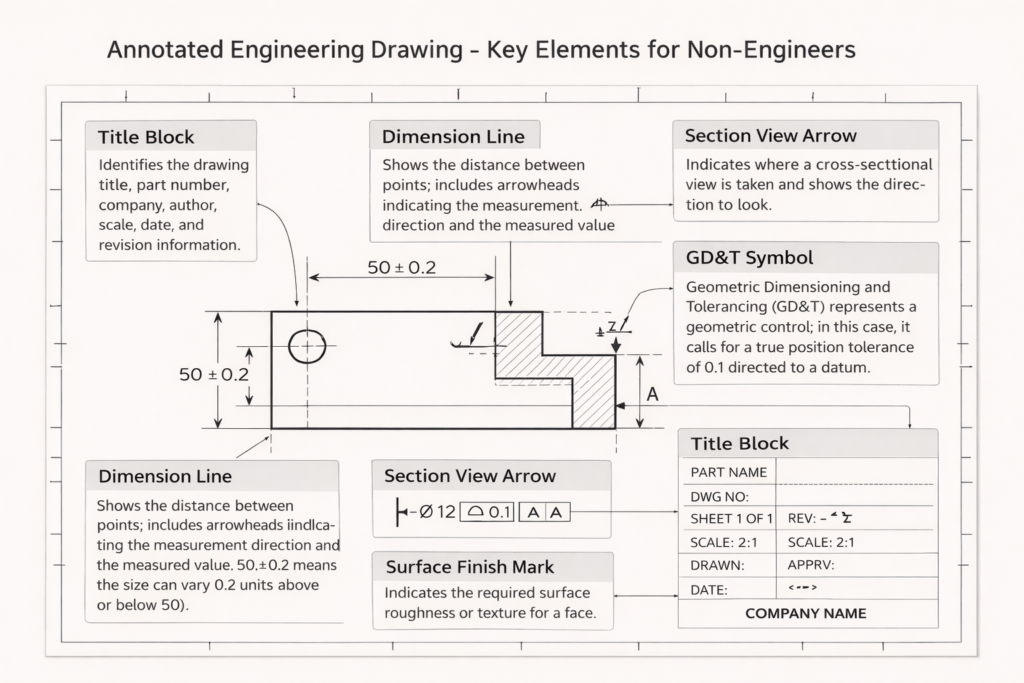
The Title Block
Every engineering drawing has a title block, usually in the bottom-right corner, that contains the part name, drawing number, revision level, material specification, scale, drawing standard (ASME or ISO), and the name of the engineer who created and approved it. This block tells you what you are looking at and whether the drawing is current. Claude can explain any field in the title block if you describe what you see.
Views and Projections
Engineering drawings typically show the same object from multiple angles, front, top, and side views, arranged in a standard layout. There may also be section views (which cut through the part to show internal features) and detail views (which zoom in on complex areas). Claude can explain why each view exists and what it is showing you.
Dimensions and Tolerances
Numbers on a drawing tell the manufacturer how big each feature is. The tolerance, shown as a plus/minus value or as a range, tells them how much variation is acceptable. When you see a dimension like ‘25.0 ±0.1’, Claude can explain what that means in practice: how precise the machinist needs to be, and what happens functionally if that tolerance is not met.
GD&T Symbols
Geometric Dimensioning and Tolerancing symbols are the most opaque part of a drawing for non-engineers. Small boxes containing geometric symbols and numbers define requirements for flatness, perpendicularity, position, and other geometric properties of features. Claude can translate these into plain language and explain why each control matters.
Notes and Specifications
Most drawings include a general notes section that specifies things like surface finish requirements, heat treatment, cleaning specifications, and drawing standards that apply across the whole part. Claude can explain any note you copy and paste in.
The Prompts to Use, and When to Use Them
These prompts are designed for the specific situations a non-engineer typically faces when dealing with engineering drawings. Use them directly in Claude, describe what you are seeing, paste text from the drawing where possible, and ask follow-up questions until you have clarity.
When You Need to Understand the Drawing Overall
| PROMPT 1: General Understanding |
| I have received an engineering drawing and I am not an engineer. I will describe what I can see on it. Please explain each element in plain language, what it means, why it is there, and what a manufacturer needs to do with it.[Describe the drawing: how many views there are, what the part appears to be, what numbers and symbols you can see, what the title block says, any notes sections, anything else that stands out] |
This is your starting point when you are looking at an unfamiliar drawing for the first time. Claude will give you a structured explanation of what each part of the drawing communicates. Take notes on the things you want to follow up on.
When You Need to Verify a Specific Dimension or Tolerance
| PROMPT 2: Tolerance Check |
| On this engineering drawing, there is a dimension that reads [describe the dimension exactly, e.g. ‘18.5 +0.0/-0.2 mm on a shaft diameter’]. Can you explain:1. What this means in plain language2. How precise the machinist needs to be3. Whether this is a tight tolerance or a loose one for this type of feature4. What would happen functionally if this tolerance was not met |
Use this when a specific dimension is being discussed in a meeting or when you want to understand whether a quoted tolerance is reasonable for the application. Claude’s answer gives you informed questions to ask your engineering team rather than having to take their answer on faith.
Read more on Prompt Engineering for CAD Drafting and Engineering Design
When You See a GD&T Symbol You Do Not Recognise
| PROMPT 3: GD&T Symbol Explanation |
| On this engineering drawing, there is a rectangular box with symbols in it. From left to right it shows: [describe what you see e.g. ‘a circle with a cross inside it, then the diameter symbol and 0.5, then the letter A’].Please explain:1. What type of geometric control this is2. What it is requiring the manufacturer to achieve3. Why this control might be on this particular feature4. What would go wrong if this requirement was ignored |
GD&T symbols are the most intimidating part of a drawing for non-engineers. This prompt turns any symbol combination into a plain-language explanation. You do not need to know what the symbol is called, just describe what you see.
When You Are Reviewing a Drawing Before Approving It
| PROMPT 4: Pre-Approval Review |
| I need to review and approve an engineering drawing before it goes to a manufacturer. I am not an engineer but I am responsible for sign-off.I will describe the drawing to you. Please help me:1. Identify the most important things to check before approving2. Flag any information that appears to be missing or incomplete3. Suggest questions I should ask the engineer before I sign off4. Highlight anything that seems unusual or worth querying[Describe the drawing in as much detail as you can] |
This prompt is for procurement leads, project managers, and technical directors who need to sign off on drawing packages without having the engineering background to evaluate them independently. Claude acts as a structured second pair of eyes, not verifying the engineering, but identifying gaps and generating informed questions.
When You Want to Understand How the Part Is Made
| PROMPT 5: Manufacturing Context |
| Based on this engineering drawing, I want to understand how this part would typically be manufactured. The drawing shows [describe: the part shape, material noted, any surface finish callouts, any notes about manufacturing process].Please explain:1. What manufacturing process would most likely be used to make this part2. Which features are the most difficult or expensive to machine3. Whether the tolerances specified look typical or unusually tight for this type of part4. What I should understand about the manufacturing process when reviewing the timeline and cost estimate |
This is particularly useful when you are evaluating a quote from a manufacturer. Understanding which features drive cost and lead time means you can have a much more productive conversation about schedule and price and spot if something in the quote does not add up.

What to Do With Claude’s Answers
Claude gives you information and language. What you do with it determines the value. A few habits that make the most of Claude’s explanations in a real engineering context:
- Write down the questions Claude’s answers generate. The goal is not to become an engineer overnight, it is to have better conversations with the engineers you work with. Use Claude to develop specific, informed questions and then take those questions to your engineering team or CAD partner.
- Do not use Claude’s output as a substitute for engineering sign-off. Claude explains and interprets, it does not verify that a design is correct, that tolerances are achievable, or that a material is appropriate for the application. Those judgments require a qualified engineer.
- Use the vocabulary Claude gives you. When Claude explains that the symbol on the drawing is a True Position control with a cylindrical tolerance zone referenced to Datum A, you now have the right terminology to ask your engineer a specific, targeted question. That changes the conversation.
- Keep a running note of terms you have looked up. Engineering drawing vocabulary is consistent, once you have learned what a feature control frame is, that knowledge applies to every drawing you encounter. Build your own glossary as you go.
Check our blog to get free 20 prompts every engineer should know
The Limits of What Claude Can Do
Claude works from descriptions. It cannot see images or PDFs directly, you need to describe what you are looking at in text. This means some nuance is inevitably lost: the exact geometry of a complex surface, the precise arrangement of views, the specific layout of a drawing that a trained engineer would read at a glance. For complex drawings, describing everything accurately enough to get a fully useful response takes effort.
Claude also cannot tell you whether the engineering itself is correct. It can explain what a tolerance means but not whether that tolerance is achievable with the manufacturing process specified. It can explain what a material designation refers to but not whether that material is appropriate for the operating environment. It can tell you what questions to ask, not whether the answers are right.
For high-stakes approvals, drawings that will go directly to manufacturing, structural components, pressure-containing parts, there is no substitute for a qualified engineering review. What Claude offers is the ability to participate meaningfully in that review process rather than being a passive spectator.
| Claude is the most useful engineering drawing tool you have access to if you are not an engineer. It is most valuable not as an answer machine, but as a question generator, giving you the language and confidence to have better conversations with the people who are. |
The Bottom Line
Engineering drawings communicate with precision in a language most people never learn. That language barrier creates real risk in product development and procurement, decisions made by people who do not fully understand what they are deciding on. Claude does not eliminate that risk, but it reduces it meaningfully by giving non-engineers a way to engage with technical drawings in plain language.
The five prompts in this guide cover the situations non-engineers encounter most often: understanding a drawing from scratch, checking a specific dimension, decoding a GD&T symbol, preparing for a sign-off review, and understanding the manufacturing implications of what is specified. Start there, follow up on anything that is not clear, and use what you learn to have better conversations with the engineers and CAD partners you work with.
Leave a Reply