2D vs 3D CAD drafting! A supplier just asked you to send over ‘the CAD files’ — and you’re not sure whether to hand them a 2D drawing package or a full 3D model. Get it wrong and you’re looking at delays, rework, and a bill for work you didn’t need.
This is one of the most common points of confusion in engineering projects, especially for teams that work with outsourced design partners or are newer to commissioning technical drawings. The truth is that 2D and 3D CAD are not competing approaches — they solve different problems at different stages of a project. Knowing which one you need, and when, saves time and money.
This guide breaks down the practical differences between 2D CAD drafting and 3D CAD modeling, explains the strengths of each, and gives you a clear framework for choosing the right approach on your next project.
What Is 2D CAD Drafting?
2D CAD drafting is the process of creating flat, precise technical drawings that communicate the geometry, dimensions, tolerances, and specifications of a part, structure, or system. Rather than showing an object as it looks in the real world, a 2D drawing presents multiple standardised views — typically a front view, a top view, and one or more side views — using a technique called orthographic projection.
Think of it as a highly structured set of instructions. A machinist reading a 2D drawing knows the exact diameter of every hole, the tolerance on every dimension, the surface finish required on a mating face, and the material the part should be made from. Everything is defined — nothing is left to interpretation.
The dominant tool for 2D drafting is AutoCAD, developed by Autodesk and widely used across architecture, civil engineering, and manufacturing. Other commonly used platforms include DraftSight and BricsCAD. Drawings are typically delivered as DWG or DXF files, or as locked PDFs for review and approval.
What a 2D Drawing Includes
- Multiple orthographic views of the part (front, top, side, section views)
- Fully annotated dimensions and tolerances
- Material specification and surface finish callouts
- GD&T symbols where geometric controls are required
- A title block with part number, revision level, scale, and drafter information
- A bill of materials (BOM) for assembly drawings
2D drawings remain the universal language of manufacturing. Even when a 3D model is used during the design phase, a 2D drawing package is almost always required before a part goes into production — because it defines the legal and contractual specification of what is to be made.
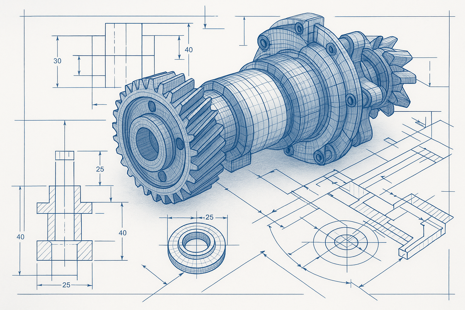
What Is 3D CAD Modeling?
3D CAD modeling creates a digital solid or surface representation of a part or assembly in three dimensions. Rather than describing a shape through projected views, a 3D model IS the shape — a virtual object that can be rotated, measured, assembled with other parts, and analysed for stress, heat, or fluid flow.
Most professional 3D CAD tools are parametric, which means every feature of the model is driven by dimensions and relationships rather than fixed geometry. Change the diameter of a shaft in SolidWorks, and every downstream feature — the shoulder, the thread, the associated drawings — updates automatically. This makes 3D modeling particularly powerful during the design and development phase, where changes are frequent.
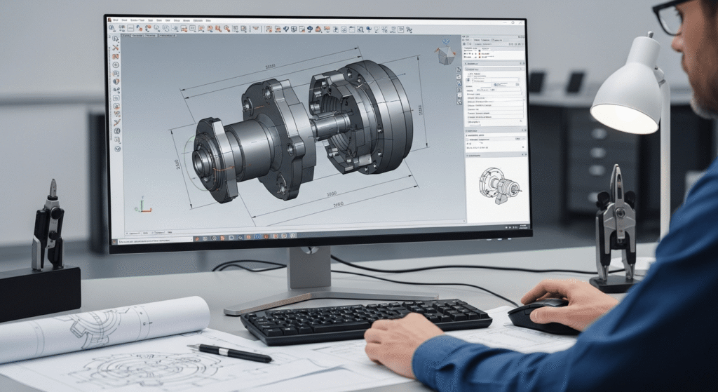
The most widely used 3D CAD platforms include SolidWorks and Autodesk Inventor for mechanical and product design, CATIA for aerospace and automotive applications, and Fusion 360 for smaller teams and startups. Files are typically shared in STEP or IGES format for interoperability, or in native formats such as .sldprt (SolidWorks) and .ipt (Inventor) when working within the same software environment.
What a 3D Model Enables
- Full visualisation and rotation before anything is physically made
- Automatic generation of 2D drawings from the 3D geometry
- Assembly modeling — checking how parts fit together and detecting clashes
- Finite Element Analysis (FEA) for structural stress and deflection testing
- Computational Fluid Dynamics (CFD) for airflow and thermal analysis
- Integration with BIM platforms for coordination on construction projects
- Direct export to 3D printing (STL format) or CNC toolpath generation
3D modeling shifts a significant amount of problem-solving earlier in the process. Issues that would previously surface on the shop floor — two pipes clashing inside a wall, a bracket that doesn’t have enough clearance for a fastener — are caught on-screen instead. That upstream investment typically pays for itself.
2D vs 3D CAD Drafting: Key Differences at a Glance
The table below summarises the most practically relevant differences between the two approaches. Keep this as a reference when briefing your design team or outsourcing partner on what deliverables you need.
| Feature | 2D CAD Drafting | 3D CAD Modeling |
|---|---|---|
| Output | Flat technical drawings (orthographic views) | Digital solid/surface model + auto-generated drawings |
| Dimensionality | Length and width (X, Y axes) | Length, width, and depth (X, Y, Z axes) |
| Primary tools | AutoCAD, DraftSight, BricsCAD | SolidWorks, Fusion 360, CATIA, Inventor |
| File outputs | DWG, DXF, PDF | STEP, IGES, native formats (.sldprt, .ipt) |
| Best for | Shop drawings, permits, simple part fabrication | New product development, assemblies, FEA, visualisation |
| Complexity | Faster for straightforward geometry | Better for complex, interdependent parts |
| Cost to produce | Lower — fewer hours for standard parts | Higher upfront; saves time in revisions and prototyping |
| Editability | Manual updates to each view | Change one parameter; all views update automatically |
Important: these two approaches are not mutually exclusive. In most professional engineering workflows, a project begins in 3D and ends with 2D. The 3D model is the design tool; the 2D drawing package is the manufacturing deliverable.
A Real-World Example: Designing a Custom Mounting Bracket
A structural fabrication company needs to design a custom steel bracket for mounting industrial HVAC units to a rooftop frame. Here is how both approaches play out on the same project:
Using 2D drafting only: The drafter produces a set of orthographic drawings showing the bracket geometry, hole positions, weld locations, and material callout (e.g. 50x50x5 RHS, Grade 350 steel). The fabricator quotes and builds directly from those drawings. This works perfectly well — the bracket is straightforward, the geometry is easy to convey in flat views, and the drawings take half a day to produce.
Using 3D modeling first: For a complex variant of the same job — say, a bespoke bracket that interfaces with three different beam profiles and needs to accommodate variable HVAC unit sizes — the engineer builds a parametric 3D model first. The model allows the team to test fit across all configurations before committing, check that nothing clashes with the rooftop drainage, and automatically generate the 2D drawings for each bracket variant. What would have taken multiple drawing revisions is resolved in the model.
The simple bracket warrants 2D. The complex multi-variant bracket warrants 3D. Same industry, same client, different choice — made based on geometry complexity and the cost of getting it wrong.
When to Use 2D Drafting vs 3D Modeling: A Practical Decision Guide
Choose 2D CAD Drafting When:
- The geometry is straightforward. Parts with simple, well-understood shapes — flat plates, standard brackets, sheet metal panels — are faster and cheaper to document in 2D.
- You are producing fabrication or shop drawings. The end deliverable for a fabricator, welder, or machinist is almost always a 2D drawing package. Even if you modelled in 3D, you will produce 2D drawings for manufacturing.
- You need construction or permit drawings. Architectural and civil permit submissions, site plans, structural general arrangement drawings, and MEP coordination drawings are typically 2D.
- You are updating legacy documentation. Existing drawing sets from older projects are in 2D. If you are revising rather than redesigning, maintaining the existing format is more efficient.
- Speed and cost are the priority. For a single, clearly defined part with no complex interfaces, 2D is quicker to produce and cheaper to commission.
Choose 3D CAD Modeling When:
- You are developing a new product or assembly. When the design intent is not yet fully resolved, 3D lets you explore, test, and iterate far more efficiently than redrawing views manually.
- Multiple parts need to fit together. 3D assembly modeling allows you to check every interface before anything is made. Clash detection on-screen is dramatically cheaper than discovering a fit problem after fabrication.
- You need to run simulation or analysis. FEA for structural loads, CFD for airflow, thermal analysis — all of these require a 3D model. You cannot run meaningful simulation on a 2D drawing.
- Your client needs to visualise the design. 3D renders and walkthroughs are far more effective communication tools than orthographic views for non-technical stakeholders, clients, and approval bodies.
- The design will change. Parametric 3D models update automatically when dimensions change. If you anticipate multiple iterations, the upfront investment in a 3D model pays back quickly in time saved on revisions.
Can You Use Both on the Same Project?
Absolutely — and in most professional engineering environments, that is exactly what happens. The 3D model is produced first as the design tool. Once the design is locked, 2D drawings are generated directly from the model, complete with dimensions, tolerances, and annotations. The 2D drawing becomes the manufacturing and contractual document; the 3D model is the source of truth for geometry.
This workflow eliminates a significant source of error: the mismatch between a manually drawn 2D document and the actual intended 3D geometry. When drawings are derived from a 3D model, they are always geometrically consistent.
Frequently Asked Questions
| Question | Answer |
|---|---|
| Is 3D CAD always better than 2D? | Not at all. 3D is more powerful for complex design work, but 2D is faster and more cost-effective for simple parts, standard fabrication drawings, and permit submissions. The right choice depends entirely on the project requirements. |
| Can a 3D model replace a 2D drawing for manufacturing? | In some advanced manufacturing environments using Model-Based Definition (MBD), yes — all specifications are embedded directly in the 3D model. But the vast majority of fabricators, machinists, and contractors still work from 2D drawings. Until MBD is universally adopted, a 2D drawing package remains the standard manufacturing deliverable. |
| What software produces both 2D drawings and 3D models? | Most professional CAD platforms do both. SolidWorks, Inventor, CATIA, and Fusion 360 all allow you to create a 3D model and then generate fully annotated 2D drawings from it within the same environment. AutoCAD has 3D capabilities but is primarily used for 2D drafting. |
| How do I know which format to request from my CAD provider? | For manufacturing: request a 2D drawing package (PDF + DWG/DXF). For design review or simulation: request a 3D model in STEP format, which is readable by all major CAD platforms. For 3D printing: request an STL file. When in doubt, ask your provider — a good engineering partner will recommend the right format for your workflow. |
The Bottom Line
2D and 3D CAD are not rivals — they are tools designed for different jobs. 2D drafting is the language of manufacturing: precise, standardised, and universally understood on the shop floor. 3D modeling is the language of design: powerful for exploring complex geometry, catching fit issues early, and communicating ideas to stakeholders.
Most engineering projects benefit from both. The key is knowing at which stage to use each — and working with a drafting partner who can deliver the right format for where your project actually is.
Ready to Get the Right Drawing for Your Project?
At SimuTecra, we deliver both 2D CAD drafting packages and full 3D models — depending on what your project actually needs. No upselling, no unnecessary complexity.
Send us your project brief and we will recommend the right approach — and give you a clear quote.
Leave a Reply