Blog

  • What is MEP Drafting? How Mechanical, Electrical, and Plumbing Designs Are Coordinated

    What is MEP Drafting? How Mechanical, Electrical, and Plumbing Designs Are Coordinated

    25-30%  of total construction budget is MEP systems on a typical commercial building (CadCrowd, 2026)
    30-40%  of site rework in building projects caused by MEP clashes discovered after construction begins (Gsource, 2026)
    10x ROI  reported on a $200,000 VDC coordination effort delivering $2.55 million in rework and schedule savings (Construction Placements, 2026)
    $47B  projected US MEP services market by 2031, growing at 6.33% CAGR from $32.55 billion in 2025 (Mordor Intelligence)

    Introduction: Why MEP Coordination Is the Most Expensive Problem in Construction

    Inside the ceiling void of a commercial building, five or more different engineering systems share a space that might be 600mm deep. HVAC ductwork. Chilled water pipework. Sprinkler mains. Electrical cable trays. Data containment. Drainage. They all need to coexist, all need to be accessible for maintenance, and all need to avoid the structural frame that fills the same space.

    When the teams designing each of those systems do not coordinate properly, the results show up on site as clashes: a duct running directly into a beam, a pipe conflicting with a cable tray, a VAV box with no service access because a riser was installed in front of it. Fixing those problems after installation costs far more than avoiding them in the drawing office. According to published construction industry research, MEP clashes account for 30 to 40 percent of all site rework on building projects.

    This guide explains how MEP drafting works, what each discipline produces, how the coordination process resolves conflicts before they reach the site, and how BIM (Building Information Modeling) tools have transformed what is possible in terms of clash detection and drawing accuracy. If you are an engineer, a project manager, a main contractor, or a client trying to understand what the MEP coordination process is supposed to deliver, this is the guide you need.

    Quick definition: MEP drafting is the process of creating technical drawings and models for the mechanical (HVAC), electrical (power and lighting), and plumbing (water and drainage) systems within a building. MEP coordination is the process of combining those discipline drawings into a single model and resolving conflicts before construction begins, typically using BIM tools like Revit and Navisworks.
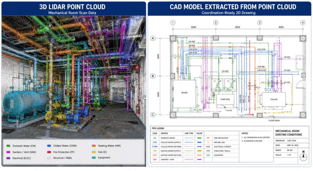
    Federated MEP Model Showing All Disciplines in a Ceiling Void
    The same ceiling void. Left: coordinated. Right: what happens without it

    What Is MEP? The Three Disciplines and What They Cover

    MEP stands for Mechanical, Electrical, and Plumbing. These three letters represent the engineering systems that make a building work. Not the structure that holds it up, and not the architecture that makes it look a certain way, but the systems that heat, cool, power, light, supply water to, drain, and protect the occupants inside.

    On larger projects, MEP expands to MEPF (adding Fire Protection) or MEPFP, and sometimes includes Low Voltage systems covering building management, security, and communications. The coordination challenge is the same regardless of how many disciplines are involved: all of these systems share the same physical building space and must be designed together, not separately.

    DisciplineWhat It CoversKey Drawing Types
    Mechanical (M)HVAC: air handling units, ductwork, VAV boxes, exhaust fans, chillers, cooling towers, boilers, thermal insulationDuctwork layouts, equipment schedules, riser diagrams, section details, air terminal schedules
    Electrical (E)Power distribution, lighting, cable trays, conduit routes, switchgear, UPS, emergency power, fire alarm, data/commsSingle-line diagrams, lighting layouts, cable tray routing, earthing layouts, load schedules
    Plumbing (P)Domestic hot and cold water, drainage, sanitary waste, roof drainage, gas supply, medical gases in healthcarePipe routing plans, isometrics, drainage layouts, sanitary riser diagrams, fixture schedules
    Fire Protection (FP)Sprinkler systems, fire mains, hydrant networks, suppression systems, smoke extractSprinkler layouts, hydraulic calculation zones, smoke control diagrams
    Low Voltage (LV)Building management systems, security, access control, CCTV, AV, voice and dataContainment routes, BMS point schedules, network topology diagrams

    Why MEP Systems Are So Difficult to Coordinate

    Each MEP discipline has its own engineers, its own design tools, its own drawing conventions, and its own technical constraints. An HVAC engineer sizes ductwork based on airflow calculations and designs routes based on equipment locations and zone requirements. An electrical engineer designs cable routes based on load distribution and switchgear locations. A plumbing engineer designs pipework based on fixture locations, gravity drainage requirements, and water pressure calculations.

    None of these engineers is primarily thinking about what the other disciplines need. The result, without a structured coordination process, is a set of designs that each work perfectly on paper but physically cannot all fit in the same building at the same time. The ceiling void that HVAC needs for a 800mm high duct is the same void that electrical needs for two layers of cable tray and that plumbing needs for a 150mm drainage pipe with a 1 in 80 fall.

    Structural steel complicates this further. Beams go where loads require them to go, not where MEP routes are conveniently planned. Without early coordination, MEP services end up routed around structural members in ways that add length, reduce efficiency, compromise building height, and cost significantly more to install than a properly coordinated design would.

    MEP Coordination Workflow Diagram: From Design to Clash-Free Model

    The MEP Drafting Process: From Brief to Coordinated Drawing Package

    Understanding the MEP drafting process in sequence helps every member of the project team understand what is supposed to happen at each stage and what information is needed from others before their work can progress. Here is the complete workflow from project brief through to a clash-free coordinated drawing package.

    Stage 1: Concept and Schematic Design

    At the earliest design stage, MEP engineers work from the architect’s concept to establish the system strategy. What type of heating and cooling system will the building use? Where will the main plant rooms be located? How will vertical risers be distributed through the floor plan? How will incoming electrical supply enter the building and route to distribution boards?

    The outputs at this stage are schematic diagrams, not detailed drawings. A schematic HVAC layout identifies the system type and main equipment. A single-line electrical diagram shows the supply route and main distribution hierarchy. These are not yet MEP coordination drawings. They are the engineering decisions that will drive everything that comes after them.

    Stage 2: Design Development and Technical Calculations

    As the architectural design firms up, MEP engineers run their technical calculations. HVAC engineers calculate heating and cooling loads room by room using thermal modelling software. They size air handling units, select chillers and boilers, and calculate ductwork cross-sections based on airflow velocities. Electrical engineers calculate connected and demand loads, select switchgear ratings, and size cable runs. Plumbing engineers size water supply pipes based on simultaneous demand and design drainage systems with the correct gradients.

    The outputs of this stage are the technical specifications and equipment schedules that drive the detailed layout drawings. Without these calculations, layout drawings are guesswork. The size of a duct is not arbitrary. It is the result of an airflow calculation that determines what cross-section is needed to deliver the required cubic metres per hour at the correct velocity for the application.

    Stage 3: Detailed Layout Drafting

    With technical parameters established, the detailed MEP layout drawings can be produced. In a BIM environment, this means each discipline builds their system in 3D within a platform like Revit MEP or MagiCAD. Every duct segment has a cross-section. Every pipe has a diameter. Every cable tray has a width and depth. Every equipment item is modelled at the correct physical dimensions.

    In a 2D CAD environment, this means annotated plan drawings for each floor level and each discipline, showing service routes, equipment locations, and connections with dimensions and specification callouts. 2D CAD-based MEP drafting is still common on smaller projects and in markets where BIM adoption is less advanced, but it produces a significantly higher coordination risk because clashes between disciplines cannot be detected automatically.

    Stage 4: Model Federation and Clash Detection

    Once each discipline has produced their detailed model or drawings, the coordination process begins. In a BIM workflow, the discipline models are uploaded to a Common Data Environment and federated in a coordination platform such as Navisworks. The federated model contains all disciplines simultaneously: structure, architecture, mechanical, electrical, plumbing, and fire protection layered together in a single 3D view.

    Clash detection software then automatically identifies every location where elements from different discipline models conflict. The clash report categorises conflicts by type, severity, and discipline combination. The coordination team reviews the report, prioritises the critical clashes, and convenes a coordination meeting with representatives from each affected trade to agree on who moves what.

    How clash detection changed everything:  Before BIM-based clash detection, coordination relied on engineers from different disciplines overlaying their drawings manually on a drawing board or a CAD screen and looking for conflicts. On a complex project with hundreds of drawings, this process was slow, expensive, and fundamentally incomplete. Software-based clash detection finds every geometric conflict in a model in seconds, producing a prioritised report that a human review process would take weeks to achieve.

    Stage 5: Coordination Meetings and Clash Resolution

    The clash report does not resolve itself. Each clash requires an engineering decision: which service moves, by how much, and in which direction? The coordination meeting is where those decisions are made, typically with the lead MEP engineer chairing and representatives from each affected discipline attending.

    Weekly coordination cycles are standard on active projects during design development. Each week, the disciplines update their models based on the previous meeting’s resolutions, re-issue to the CDE, the federation is updated, and a new clash run is performed. The number of outstanding clashes should decrease each cycle until a clash-free status is achieved.

    In practice, achieving zero hard clashes is realistic. Achieving zero soft clashes is typically not, because some soft clash rules are conservative and the actual installation can accommodate tighter clearances than the rule specifies. The goal is to resolve all critical hard clashes and all soft clashes in areas where service access or installation sequence would be compromised.

    Stage 6: Coordinated Drawing Production

    With a clash-free or clash-minimised model, coordinated drawings can be produced directly from the 3D model. Floor plan layouts, section views through congested areas, riser diagrams, and spool drawings for prefabrication are all derived from the coordinated geometry rather than drafted independently. This is where BIM delivers one of its highest-value outputs: the drawing and the model are always consistent because one is generated from the other.

    Types of Clashes in MEP Coordination and How Each Is Resolved

    Not all clashes are equal. MEP clash detection identifies conflicts in several categories, each with different implications for how urgently they need to be resolved and what the resolution options are.

    Clash TypeDefinitionCommon MEP Examples
    Hard clashTwo objects physically occupy the same spaceHVAC duct running through a structural beam; sprinkler pipe through electrical panel
    Soft clashObjects are within a defined clearance zone of each otherElectrical cable tray within 100mm of fire sprinkler main; VAV box within 200mm of beam soffit
    Workflow clashTiming or sequencing conflict between tradesElectrical conduit installed before plumbing sleeve, blocking pipe route; equipment needing access panels that are walled off
    Tolerance clashCumulative dimensional errors within acceptable individual tolerancesThree adjacent services each within tolerance but together exceeding available ceiling void space

    The Real Cost of Late Clash Discovery

    Published data on MEP rework consistently shows that the cost of resolving a clash increases by an order of magnitude at each stage of the construction process. A clash resolved in the design coordination model costs the time of an engineer and a revision to a drawing. The same clash discovered during installation requires dismantling what is already installed, redesigning the route, procuring new materials, and reinstalling. On complex projects, a single late-discovered clash in a congested riser can cost tens of thousands and delay multiple trades that were waiting for that riser to be complete.

    The published case study data is striking. A $200,000 investment in Virtual Design and Construction coordination on one referenced project delivered $2.55 million in rework and schedule savings, a return on investment of more than ten to one. These are not theoretical figures. They are documented outcomes from structured BIM MEP coordination programs on real construction projects.

    MEP Service Routing Priority: Who Moves When There Is a Conflict

    One of the most practically useful things an MEP coordinator or project engineer can know is the routing priority hierarchy. When two services conflict and one must move, the decision about which one gives way is not arbitrary. It follows a physical logic based on the routing flexibility of each service type.

    PriorityService TypeWhy It Has PriorityRouting Flexibility
    1Gravity drainage and sewageCannot change gradient without redesignVery low. Fixed slope dictates route.
    2Large HVAC ductworkLarge cross-section, difficult to rerouteLow. Major re-routes require load recalculation.
    3Pressurised chilled water and heating pipeworkCan use bends and rises but costly to rerouteMedium. Fittings add cost but direction is flexible.
    4Electrical cable traysFlexible, can change direction easilyHigh. Small section, many routing options.
    5Electrical conduit and cablesMost flexible service on siteVery high. Can be rerouted with minimal cost.

    Gravity Drainage: The Immovable Starting Point

    Gravity drainage is the service with the least routing flexibility of all MEP systems and therefore takes absolute priority in space allocation. A drainage pipe must fall continuously from the point of use to the point of discharge at the required gradient. Typically 1 in 80 for branch drains and steeper for shorter runs. You cannot add bends to a gravity drainage pipe without either raising the starting point or dropping the discharge point, both of which may be impossible given the floor-to-floor height and the slab structure.

    This is why drainage routes must be established first in the coordination process, before other services claim the ceiling void space that the drainage gradient requires. On projects with tight floor-to-floor heights, drainage routing is often the determining factor in whether certain ceiling heights are achievable at all.

    Large Ductwork: The Second Immovable Constraint

    HVAC ductwork, particularly main trunk ducts feeding large air handling systems, comes second in the priority hierarchy. A duct serving a 10,000 square metre open-plan floor might be 800mm wide and 400mm deep. It cannot be reduced in cross-section without increasing air velocity beyond the noise and efficiency limits. It cannot be routed around structural members without increasing fan power and potentially redesigning the entire distribution system.

    Ductwork also changes cross-section as it branches. The main trunk duct is the largest. First-order branches are smaller. Final room terminals are smallest. The coordination drawing must show this reduction in cross-section accurately because it determines the clearances available for other services at each point along the route.

    Practical coordination rule:  Always ask the HVAC engineer to model their ductwork first in any zone where ceiling height is constrained. Everything else coordinates around the ductwork and drainage. Trying to fit ductwork around already-placed electrical and plumbing services almost always requires rework from all disciplines.

    MEP Drawing Types: What Each Drawing Communicates and Who Uses It

    A complete MEP drawing package contains multiple types of drawings, each serving a specific purpose in the construction and operation of the building. Understanding what each drawing type communicates prevents the common problem of contractors using the wrong drawing for the wrong purpose.

    MEP Drawing Types Reference: Layout Plan vs Riser Diagram vs Spool Drawing
    Each drawing type serves a different purpose. Using the wrong one for the wrong task causes errors.
    Drawing TypeWhat It ShowsWho Uses It
    Layout planPlan view of MEP system routes at each floor levelDesign consultants, contractors, building control
    Riser diagramVertical representation of pipe or duct routing through floorsCoordination team, commissioning engineers
    Single-line diagramSimplified electrical system showing circuit relationshipsElectrical engineers, building control, FM teams
    Section drawingCut-through view showing services stacked in a corridor or ceiling voidCoordination team to verify spatial fit
    Isometric drawing3D representation of pipe runs for fabricationPlumbing and mechanical fabricators
    Spool drawingFabrication drawing for a specific prefabricated sectionOffsite prefabrication workshops
    Equipment scheduleData table for each equipment item: model, capacity, connectionsProcurement, commissioning, FM teams
    Coordination drawingCombined overlay of all MEP disciplines in one viewMain contractor, all MEP subcontractors
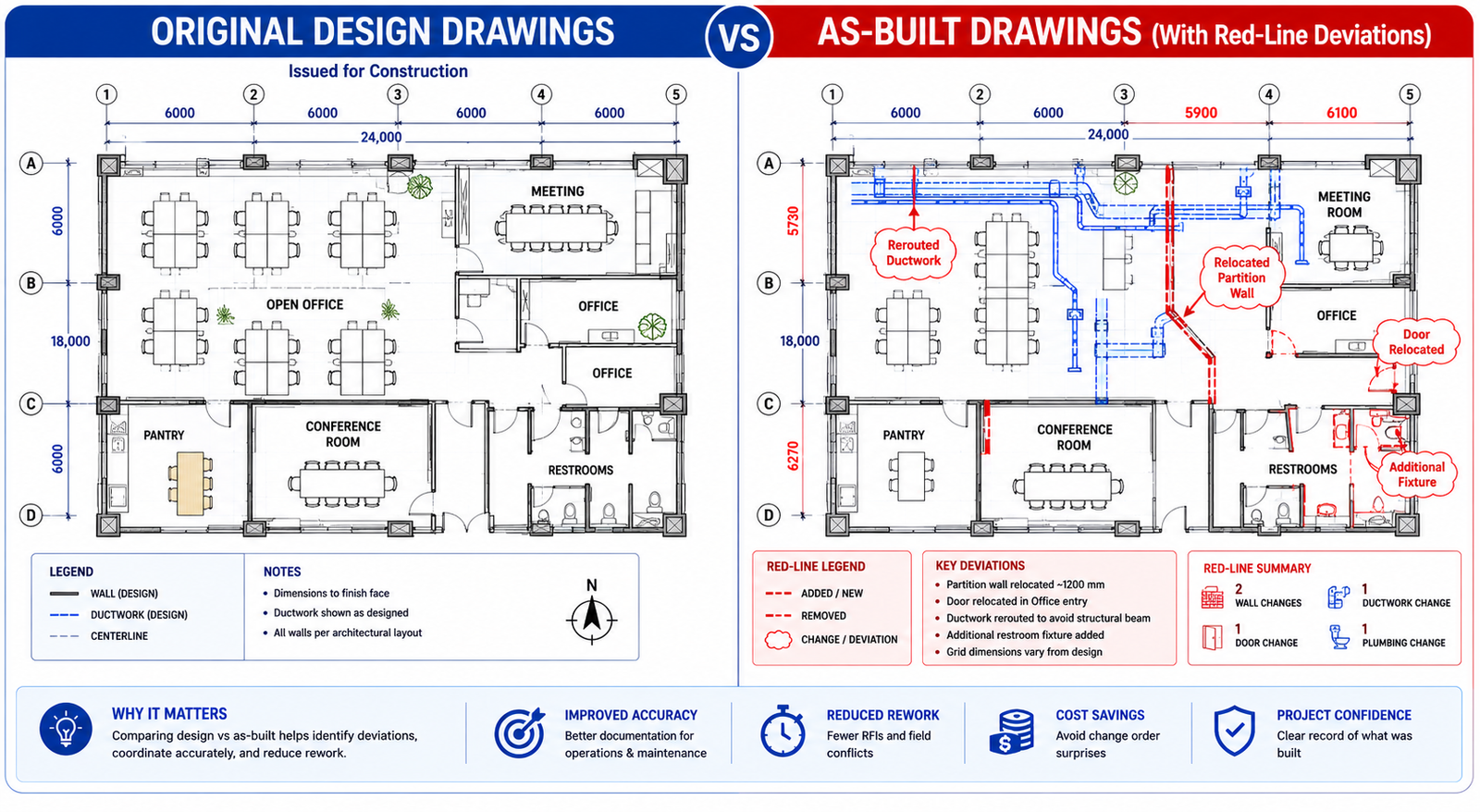
    As-built drawingFinal record of installed positions after constructionFM teams, future maintenance, decommissioning

    Spool Drawings and the Prefabrication Advantage

    Spool drawings are among the most valuable outputs of a well-executed BIM coordination process. A spool is a prefabricated section of pipework or ductwork, assembled in a controlled workshop environment and delivered to site ready to connect. Spool drawings specify every dimension, every fitting, every weld or flange, and every connection point for that prefabricated section.

    The advantage of prefabrication is significant. Workshop fabrication is faster, produces higher-quality welds and connections, requires less site safety management, and removes trade congestion from a busy site during critical installation windows. But it only works if the drawings are accurate and the model was clash-free when the spools were generated. A spool fabricated from a pre-coordination model is a spool that may not fit when it arrives on site.

    This is why the sequence matters: coordination complete first, spool drawings issued after. On projects where this sequence is violated, either because of schedule pressure or inadequate coordination process management, the result is fabricated sections that require modification on site, eliminating most of the cost and time advantage that prefabrication was meant to deliver.

    MEP Drafting and Coordination Software: What Teams Actually Use

    The MEP software landscape in 2026 is dominated by the Autodesk platform for most global markets, with specialist tools serving specific disciplines and project types. Understanding which tool does what helps project managers set realistic expectations about workflow and deliverables.

    SoftwareDeveloperPrimary UseMEP Discipline StrengthBIM Level
    Autodesk Revit MEPAutodeskFull BIM MEP modelingMech, Elec, PlumbingLevel 2+
    AutoCAD MEPAutodesk2D/3D MEP draftingAll disciplinesLevel 1
    NavisworksAutodeskClash detection, federationAll (coordination tool)Level 2+
    MagiCADProgmanMEP modeling in Revit/CADStrong mechanical and HVACLevel 2
    Bentley OpenMEPBentleyMEP design in OpenBuildingsAll disciplinesLevel 2+
    Trimble MEPTrimbleFabrication and fieldMechanical, plumbingFabrication
    Dialux / ReluxVariousLighting design / calculationElectrical (lighting)Specialist
    IES VEIESBuilding energy simulationMechanical (HVAC loads)Specialist
    AutoCAD ElectricalAutodeskElectrical panel and wiringElectrical schematicsLevel 1

    Revit MEP: The BIM Coordination Standard

    Autodesk Revit MEP is the most widely adopted BIM platform for MEP drafting globally. Its discipline-specific worksets allow mechanical, electrical, and plumbing engineers to work within the same project file simultaneously, with each discipline’s work visible to others in real time. Equipment families carry full technical data: a VAV box in Revit knows its airflow rate, its connection size, its service zone, and its maintenance access requirement.

    The integration between Revit and Navisworks for clash detection is the most common coordination pipeline in UK, US, European, and Australian markets. Revit produces the discipline models. Navisworks federates them, runs clash detection, and generates the clash report. The coordination team resolves clashes, engineers update the Revit models, and the cycle repeats.

    Navisworks: The Coordination Engine

    Navisworks is not a modeling tool. It is a coordination and review platform that reads models from virtually any 3D software platform and federates them into a single review environment. Its ClashDetective module runs automated clash detection against user-defined rules, producing clash reports that can be sorted by discipline pair, clash type, and severity.

    The practical advantage of Navisworks is its format agnosticism. A project where the architect models in ArchiCAD, the structural engineer in Tekla, and the MEP team in Revit can still be federated in Navisworks because all three platforms export to NWC or IFC format that Navisworks reads. Navisworks is the coordination tool that works regardless of what each discipline used to build their model.

    8 MEP Coordination Mistakes That Cause Expensive On-Site Problems

    The majority of MEP coordination failures on site trace back to a small number of process failures that are well understood and entirely preventable. These are the mistakes that experienced MEP coordinators see repeatedly, and they are the ones that account for the majority of the rework costs documented in published construction industry research.

    MistakeWhat Goes Wrong On SiteHow to Prevent It
    No coordination meeting before modelingEach discipline drafts in isolation, clashes not found until federationRun a pre-design coordination meeting. Agree corridor zones, ceiling void allocation, and riser routes before any trade starts modeling.
    Missing clearance zones in clash rulesSoft clashes ignored, services too close to maintainDefine clearance rules in Navisworks before the first clash run. 100mm minimum from electrical to fire main is a standard starting rule.
    Outdated model versions in federationClash detection run on stale geometry, clashes missedEnforce CDE version control. Never federate models older than the agreed issue cycle, typically weekly.
    Structural model not includedMEP routes through beams discovered on siteAlways include the structural model in the federated coordination model. Structural clashes are the most expensive to fix on site.
    LOD mismatch between disciplinesOne trade models at LOD 200, another at LOD 350. False soft clashes appear.Agree LOD expectations per discipline per RIBA stage before modeling begins. Document in the BEP.
    No priority hierarchy for routingLower-priority services occupy prime routes, pushing high-priority services into awkward pathsEstablish routing priority: gravity drainage first, then ductwork, then pressurised pipework, then cable trays and conduit.
    As-built drawings not updatedFM teams have no record of where services run. Maintenance causes costly disruption.Make as-built model update a contractual delivery requirement with a practical completion check.
    Spool drawings issued before coordination completePrefabricated sections do not fit because model was not yet clash-freeLock spool drawing issue until coordination sign-off is complete for the relevant zone.

    The most expensive single mistake in MEP coordination:  Issuing spool drawings for prefabrication before the clash detection process is complete for the relevant zone. On one documented project, prefabricated pipework sections totalling GBP 340,000 required on-site modification because spool drawings were issued three weeks before the coordination model for that floor was signed off. The modification cost exceeded the original fabrication saving.

    BIM and AI in MEP Coordination: What Is Actually Changing in 2026

    The relationship between BIM MEP coordination and artificial intelligence in 2026 is moving from early adoption to practical implementation across the MEP sector. The improvements are not theoretical. They are showing up in reduced coordination meeting times, faster clash resolution cycles, and more reliable spool drawing production.

    AI-Assisted Clash Prioritisation

    One of the most time-consuming aspects of MEP coordination has always been reviewing clash reports that contain thousands of individual conflicts, many of which are low-priority soft clashes or duplicate detections of the same fundamental routing problem. AI tools are beginning to prioritise clash reports automatically: grouping related clashes that share a common root cause, flagging critical structural clashes for immediate escalation, and filtering out soft clashes that fall within acceptable installation tolerance.

    This reduces the time coordination teams spend in clash review meetings significantly. One project team using AI-assisted clash review reported completing weekly coordination cycles in 40 percent of the time compared to manual clash report review, because the AI filtering removed approximately two-thirds of the reported clashes that required no engineering decision.

    Generative Design for MEP Routing

    Generative design tools are beginning to be applied to MEP service routing problems, particularly in constrained ceiling void conditions. Given the structural model, the architectural model, the service routing priority hierarchy, and the spatial constraints of the ceiling void, generative design algorithms can propose multiple valid routing configurations that avoid hard clashes before any human engineer begins the layout.

    This does not remove the engineer from the process. It provides a starting point that is already clash-free with the structure and the architectural envelope, allowing the coordination team to focus on inter-service coordination rather than spending time avoiding the structural frame manually. On high-density projects with multiple competing services in constrained ceiling voids, this starting point advantage is measurably valuable.

    Digital Twins and Operational MEP Management

    The fully coordinated BIM model that is produced at the end of a successful MEP coordination process is increasingly being maintained as a digital twin through the building’s operational life. Sensor data from installed equipment, maintenance records, energy consumption logs, and inspection reports are connected to the building model so that facilities management teams have a continuously updated picture of system status.

    For MEP systems, the digital twin enables predictive maintenance based on equipment performance data, energy optimisation by comparing actual versus modelled consumption, and renovation planning using the as-built model rather than attempting to survey hidden services. The condition precedent for all of these benefits is that the as-built MEP model was delivered accurately at project completion, which requires the same coordination discipline that produces a clash-free construction model in the first place.

    AI for MEP Documentation

    The documentation layer of MEP projects, producing equipment schedules, operation and maintenance manuals, commissioning records, and handover packages, is one of the most time-consuming aspects of project delivery and one of the areas where AI tools are delivering immediate practical benefit. Structured data extracted from a coordinated BIM model can be processed by AI tools to generate formatted O and M manuals, equipment registers, and maintenance schedules in a fraction of the time required for manual preparation.

    For MEP engineers and project managers using tools like Claude for documentation assistance, the combination of structured BIM data output and AI-driven document generation produces handover packages that are both faster to produce and more complete than manually compiled equivalents. The technical content comes from the model. The communication layer comes from AI.

    Real-World Example: MEP Coordination on a Commercial Office Building

    To make the coordination process concrete, here is how it plays out on a typical commercial office development: ten floors, 2,500 square metres per floor, mixed open-plan and cellular office layout with a central core containing lifts, toilets, and risers.

    The Coordination Challenge

    The typical floor-to-floor height is 4.0 metres. The structural concrete flat slab is 300mm deep. The raised access floor adds 150mm. The finished ceiling sits at 2.7 metres above finished floor level. That leaves a ceiling void of 4,000 minus 300 minus 150 minus 2,700 = 850mm in which to fit all MEP services.

    In that 850mm, the team needs to route: primary HVAC supply ductwork at 500mm x 200mm, chilled water pipework at 150mm diameter plus insulation, primary drainage at 100mm diameter with a 1 in 80 fall, electrical cable trays at 600mm wide and 100mm deep, sprinkler mains at 100mm diameter, and data containment at 200mm wide. Without coordination, these services will not all fit. They need to be stacked and sequenced, with priority given to drainage and ductwork, and the remaining services fitted around them.

    The Coordination Outcome

    After four weekly coordination cycles on a project of this type, a well-managed BIM coordination process resolves the vast majority of hard clashes and produces a coordinated ceiling void arrangement that is signed off by all disciplines. The outputs include a set of coordinated floor plans and ceiling sections for each typical floor, a fully resolved riser diagram, spool drawings for the prefabricated pipework sections, and an agreed installation sequence for each zone that allows trades to work without blocking each other.

    The value of this output is not just avoiding the on-site clashes. It is the confidence that the contractors installing each system know exactly where their services run, where they connect, and in what sequence. That certainty drives faster installation, more reliable programme adherence, and a significantly smoother commissioning process where systems can be tested as designed because they were installed as coordinated.

    Conclusion: MEP Coordination Is Not a Task. It Is a Project-Level Commitment.

    The statistics on MEP rework, 30 to 40 percent of site rework caused by coordination failures, ten-to-one ROI on structured coordination programs, are not abstract numbers. They are the documented outcome of a choice that every project team makes: either invest in coordination during design, or pay a significantly higher price for the same problems during construction.

    A well-executed MEP drafting and coordination process does not guarantee a perfect project. But it systematically eliminates the category of problems that are most expensive to fix on site, most disruptive to programme, and most damaging to relationships between contractors who are trying to work in the same physical space at the same time.

    In 2026, BIM MEP coordination using Revit and Navisworks is the established standard on any commercial, healthcare, education, or mixed-use project above a certain scale. AI tools are beginning to accelerate the clash review process, improve routing proposals, and automate the documentation that sits around the coordination work. The fundamentals, model each discipline accurately, federate regularly, resolve hard clashes before they reach site, and issue coordinated drawings for construction, have not changed and will not change.

    Understand the process. Enforce the sequence. Demand the deliverables. The building performance and the project budget both depend on it.

    A clash found in a coordination model costs minutes. The same clash found on site costs weeks.

    Frequently Asked Questions

    What is MEP drafting?

    MEP drafting is the process of creating technical drawings and models for the mechanical, electrical, and plumbing systems within a building or infrastructure project. These drawings communicate the layout, routing, sizing, and specifications of HVAC systems, power distribution, lighting, water supply, drainage, and fire protection to contractors, engineers, and building managers who will install and operate those systems.

    What is MEP coordination and why does it matter?

    MEP coordination is the process of integrating the individual mechanical, electrical, plumbing, structural, and architectural models into a single federated model and resolving spatial conflicts before construction begins. It matters because all MEP services share the same ceiling voids, vertical risers, and plant rooms. Without coordination, services clash on site and rework can consume 30 to 40 percent of MEP site labour hours according to published construction industry research.

    What is the difference between a hard clash and a soft clash in MEP?

    A hard clash occurs when two building elements physically occupy the same space. For example, an HVAC duct routed directly through a structural beam. A soft clash occurs when two elements are within a defined clearance zone of each other without touching, for example an electrical cable tray within 100mm of a fire sprinkler main. Hard clashes are always critical. Soft clashes require engineering judgment about whether the clearance is sufficient for installation, operation, and maintenance access.

    What software is used for MEP drafting and coordination?

    The most widely used software for MEP drafting and coordination in 2026 is Autodesk Revit MEP for BIM-based 3D modeling and Autodesk Navisworks for clash detection and model federation. AutoCAD MEP handles 2D drafting workflows. MagiCAD adds specialist MEP capabilities within Revit. Trimble supports prefabrication and field installation. Specialist tools include Dialux for lighting design and IES VE for HVAC load calculations.

    What is a spool drawing in MEP?

    A spool drawing is a fabrication drawing for a specific prefabricated section of pipework or ductwork. It shows the exact dimensions, material specifications, connection types, and weld or flange positions for a section that will be fabricated off-site and installed as a complete unit. Spool drawings are generated from the coordinated BIM model after clash detection is complete, so the fabricated section is guaranteed to fit when it arrives on site.

    How does AI improve MEP drafting and coordination workflows?

    AI is improving MEP workflows in 2026 in four practical ways. AI-assisted clash prioritisation ranks detected clashes by severity automatically, reducing the time coordination teams spend reviewing low-impact soft clashes. Generative design tools explore optimal routing paths for ductwork and pipework given the spatial constraints of a ceiling void. Automated drawing production generates 2D drawings directly from the coordinated 3D model. And natural language tools allow project managers to query the BIM model and receive MEP status reports without needing to navigate the model directly.


    buildingSMART International — IFC and OpenBIM Standards for MEP Coordination

  • How CAD Drafting Is Used in Structural Steel Detailing | SimuTecra

    How CAD Drafting Is Used in Structural Steel Detailing | SimuTecra

    A structural engineer’s design drawings tell you what to build. A steel detailer’s shop drawings tell you exactly how to build it. Without that second set of documents, fabricators are left guessing, and guessing in structural steel is a problem that shows up on-site as misaligned connections, wrong-length members, and weeks of expensive rework.

    Structural steel detailing is the discipline that bridges the gap between engineering design and fabrication. It takes the structural engineer’s intent, member sizes, load paths, connection zones, and translates it into manufacturing-ready drawings that a steel fabricator can actually work from. This guide explains what steel detailing is, what a complete shop drawing package includes, how the process works, and what happens when any part of it is done poorly.

    Structural steel shop drawing showing beam and column layout with member marks, dimensions, and connection references
    A typical structural steel shop drawing package, the fabrication document that turns engineering design into build-ready instructions.

    What Is Structural Steel Detailing?

    Structural steel detailing is the process of producing detailed technical drawings for every component of a steel-framed structure, every column, beam, brace, connection plate, and anchor bolt, with enough precision that a fabricator can manufacture each piece in a workshop without ever visiting the construction site.

    The structural engineer defines the design: which member sizes carry which loads, where the columns go, what the connection zones look like. The steel detailer translates that design into fabrication instructions: exact cut lengths, hole patterns, weld specifications, bolt grades, member mark numbers, and surface treatment requirements. These are two fundamentally different documents serving two different audiences.

    Structural engineers define the ‘what’ and ‘why’ of a steel structure. Steel detailers define the ‘how’, in enough detail that fabrication can begin without further interpretation.

    In practice, structural engineers do not typically produce shop drawings, and fabricators cannot manufacture complex steelwork from structural design drawings alone. The detailer occupies the critical middle ground, and their work directly determines whether steel arrives on site fitting correctly or requiring costly modification.

    Who Uses Steel Shop Drawings?

    • Steel fabricators: Use shop drawings as the primary manufacturing document. Every cut, drill, bend, and weld is made to the shop drawing specification.
    • Site erectors: Use erection drawings (a subset of the shop drawing package) to locate, orient, and assemble steel members in the correct sequence.
    • Structural engineers: Review and approve shop drawings before fabrication begins, confirming they accurately represent the design intent.
    • Contractors and project managers: Use the drawing package for programme planning, procurement, and site coordination with other trades.
    • Inspectors and certifiers: Reference shop drawings during quality assurance inspections to verify that fabricated members match the approved specification.

    What a Complete Steel Shop Drawing Package Includes

    A shop drawing package is not a single sheet, it is a coordinated set of documents covering every aspect of the steel structure from overall layout down to individual component fabrication. Here are the five core drawing types that make up a complete package:

    Drawing TypeWhat It ShowsWho Uses It
    General Arrangement (GA) DrawingThe overall steel framework, column grid, beam layout, levels, key dimensions, and member mark references. The big-picture roadmap of the structure.All stakeholders: engineers, fabricators, erectors, contractors. Always the first document reviewed.
    Fabrication Shop DrawingIndividual member details, exact lengths, cross-section sizes, hole locations, end cuts, weld preparation, surface treatment, and member mark numbers.Steel fabricator in the workshop. This is the primary manufacturing document.
    Connection Detail DrawingHow members are joined, end plate dimensions, bolt specifications (grade, size, spacing), weld types (fillet, groove), stiffener plates, cleats, and gussets.Fabricator and structural engineer. Connection details are the most safety-critical drawings in the package.
    Erection DrawingSite assembly instructions, member marks matched to positions on the structure, erection sequence, temporary bracing requirements, and orientation notes.Site erectors and crane operators. Governs how and in what order steel goes up.
    Anchor Bolt / Baseplate DrawingThe interface between the steel structure and its foundations, anchor bolt patterns, projection heights, baseplate dimensions, grout details.Civil/structural engineer and site team. Must be issued before concrete is poured.

    What a Fabrication Shop Drawing Contains in Detail

    The fabrication drawing is the most detail-intensive document in the package. For every individual steel member, whether it is a 200 mm universal column or a 12 m long crane beam, the fabrication drawing includes:

    • Member mark number (a unique identifier used to track the piece from workshop to site)
    • Cross-section size and steel grade (e.g. 310UC97 Grade 350, or W12x96 A992)
    • Overall length and end-to-end dimensions
    • Hole pattern: diameter, spacing, edge distance, and bolt gauge lines for every connection
    • End preparation: square cut, coped, notched, or shaped to suit the connection
    • Weld callouts: weld type, size, length, and location using standard weld symbols
    • Stiffener plates, web plates, flange plates, and any additional fabricated elements
    • Surface finish: bare steel, primed, hot-dip galvanised, or intumescent coated
    • Weight of the finished member (for crane planning and logistics)
    A typical structural steel shop drawing package, the fabrication document that turns engineering design into build-ready instructions.
    Connection detail drawings specify every bolt, weld, and plate dimension, leaving no interpretation to the fabricator.
    Common problem: Connection details are the most frequently incomplete element of a structural engineer’s drawing package. When connection geometry is not specified by the engineer, the steel detailer is responsible for designing and calculating the connections, adding scope, time, and coordination requirements to the detailing process. Clarify this responsibility before starting any steel detailing engagement.

    The Steel Detailing Process: From Design Intent to Fabrication-Ready Drawings

    Steel detailing follows a structured sequence. Compressing or skipping any stage increases the risk of errors that compound through fabrication and into site installation. Here is how a properly managed steel detailing process works:

    Stage 1: Design Review and Input Gathering

    The detailer starts by reviewing the structural engineer’s drawings in full, checking member sizes, connection zones, load transfer paths, and any special requirements. Before any drawing is started, every piece of missing information is identified and resolved. Structural drawings that leave connection design to the detailer require additional coordination before work can begin.

    Best practice: Issue a formal Request for Information (RFI) log at the start of every steel detailing project. Capturing all ambiguities before detailing starts prevents revision cycles later, each revision to a fabrication drawing after approval costs far more than the time spent resolving the RFI upfront.

    Stage 2: 3D Modelling

    Most professional steel detailing today begins with a 3D model built in Tekla Structures, Advance Steel (AutoCAD), or Revit. The structural framework is modelled in full, every column, beam, brace, connection plate, and bolt, before any 2D drawings are produced. The 3D model serves as the single source of truth for all geometry.

    The 3D modelling stage is where clash detection happens: two members occupying the same space, a beam centreline that misses the column by 20 mm, a stiffener plate that conflicts with a bolt head. Catching these in the model costs minutes. Catching them during fabrication costs days.

    Stage 3: Drawing Generation and Annotation

    With the 3D model complete and clash-free, 2D fabrication drawings are generated directly from the model geometry. Each drawing is then annotated with member marks, dimensions, hole callouts, weld symbols, material grades, surface treatment, and any special notes. The drawings are checked against the structural engineer’s specifications and reviewed internally before submission.

    Stage 4: Engineer Review and Approval

    The complete drawing package is submitted to the structural engineer of record for review. The engineer checks that every drawing accurately reflects the design intent, member sizes, connection types, load paths, and any project-specific requirements. Comments are returned, revisions are made, and the cycle continues until the drawings receive an approved-for-fabrication stamp.

    Drawings issued for fabrication without engineer approval are a liability risk for every party in the supply chain. Approved-for-fabrication status is a non-negotiable gate before any steel is cut.

    Stage 5: Issue and Fabrication

    Approved drawings are issued to the fabricator, along with any associated NC (numerical control) data files for automated cutting and drilling equipment. The fabricator manufactures each member to the drawing specification, marks it with its member number, and stages it for delivery to site in erection sequence.

    Structural steel building frame being erected on a construction site, with columns and beams assembled from shop-fabricated and marked steel members
    Every member arriving on site has been cut, drilled, and marked in the fabrication shop to the approved shop drawing, making erection a process of assembly, not guesswork.

    What Happens When Steel Detailing Is Done Poorly

    The consequences of poor steel detailing are not abstract, they appear as concrete, measurable problems on the fabrication floor and construction site. Here are the most common failure modes and what they cost:

    ProblemHow It Manifests on SiteTypical Cost Impact
    Incorrect hole patternsBolts do not align when members are brought together on site. Holes must be reamed, slotted, or in severe cases the member returned for refabrication.High. Reaming is labour-intensive; refabrication requires remobilising the fabricator and delays the erection programme.
    Wrong member lengthsBeams arrive too long or too short for their connections. Short members may require extension plates; long members cannot be forced into position.High. Extension plating requires engineer approval and adds welding work on site, where quality control is harder than in the workshop.
    Missing connection detailsFabricator encounters a connection type not shown on the drawings and makes an assumption. The assumption is wrong. Connection is built incorrectly.Very high. Structural integrity is compromised. Engineer review, remediation work, and potential programme shutdown may follow.
    Outdated revision used for fabricationSteel is manufactured to a superseded revision of the drawing. Members arrive on site that do not match the current design intent.High to very high depending on scope. Worst case is a full batch of steel scrapped and refabricated.
    Clashes not resolved before fabricationTwo members designed to share the same space conflict during erection. Field modifications are made on site without engineering review.Medium to high. Field modifications are expensive, slow, and often structurally suboptimal. Liability exposure increases significantly.

    Standards That Govern Structural Steel Detailing

    Steel detailing does not operate in a standards vacuum. The drawings must comply with the applicable structural design code and the industry standards governing fabrication quality and drawing presentation. The most commonly referenced are:

    • AISC (American Institute of Steel Construction): Governs structural steel design and fabrication in the United States. The AISC Code of Standard Practice defines the division of responsibility between engineers, detailers, and fabricators, including who is responsible for connection design when not specified by the engineer.
    • AWS D1.1 (American Welding Society): The structural welding code referenced on US shop drawings for all weld specifications. Weld symbols, procedures, and inspection requirements are governed by this standard.
    • ASTM material standards: Define the steel grade (e.g. ASTM A992 for wide flange sections, ASTM A36 for plates). Material callouts on shop drawings reference these standards directly.
    • Eurocode 3 / BS EN 1993: The structural steel design standard used across Europe and increasingly in international projects. Detailing conventions differ from AISC in member designation, weld symbols, and bolt standards.

    For international projects: Always confirm which standard set applies before beginning detailing. A drawing package produced to AISC standards and submitted to a European fabricator may use member designation systems, weld symbols, and bolt standards that the fabricator interprets differently. Agreeing the applicable standards at the start of the project is a 30-minute conversation that prevents a multi-week misunderstanding.

    Frequently Asked Questions

    What is the difference between structural engineer’s drawings and shop drawings?

    Structural engineer’s drawings define the design, member sizes, load paths, connection zones, and overall layout. They communicate design intent but typically do not contain enough fabrication detail to manufacture from directly. Shop drawings, produced by the steel detailer, translate that design into exact manufacturing instructions: cut lengths, hole patterns, weld callouts, and surface treatments. Both sets of drawings are required on any significant steel project.

    What software is used for structural steel detailing?

    Tekla Structures (by Trimble) is the most widely used dedicated steel detailing platform, particularly for complex projects. Advance Steel (Autodesk, built on AutoCAD) is common in North America and Australia. Revit with structural extensions is used where BIM coordination is the primary requirement. Traditional 2D detailing is still done in AutoCAD for simpler projects or where the client requires 2D-only deliverables.

    Who is responsible for connection design, the engineer or the detailer?

    This depends on what the structural engineer’s drawings specify. Where connection geometry is fully specified by the engineer, the detailer documents it. Where connections are left unspecified or noted as ‘connection by detailer’, the steel detailer is responsible for designing and calculating the connection, a responsibility that requires structural knowledge, not just drafting skill. The AISC Code of Standard Practice governs this split of responsibility in the US.

    How long does a steel detailing package take to produce?

    It depends entirely on the scope and complexity of the structure. A simple single-storey industrial shed might be detailed in one to two weeks. A multi-storey commercial building with complex connections and BIM coordination requirements could take two to four months. The critical path items are always the completeness of the input drawings, the speed of engineer review and approval, and the management of RFIs. Incomplete inputs are the most common cause of detailing delays.

    What file formats are delivered as part of a steel detailing package?

    Typically: PDF (for drawing review and site use), DWG or DXF (for 2D CAD files), and IFC or native Tekla/Revit files (for 3D BIM model delivery). NC files (CNC cutting and drilling data) are often included for modern fabrication facilities with automated equipment. The required formats should be agreed with the fabricator and engineer before detailing begins.

    The Bottom Line

    Structural steel detailing is not a back-office function, it is the document control system that determines whether a steel structure gets built correctly, on time, and without costly surprises. Every bolt, weld, and cut on the fabrication floor is made to a shop drawing. When those drawings are complete, coordinated, and approved, fabrication runs smoothly and steel arrives on site fitting where it should.

    When they are incomplete, ambiguous, or produced from inadequate inputs, the problems that follow, misaligned connections, wrong-length members, clashing geometry, rejected inspections, are expensive, time-consuming, and entirely avoidable with a properly managed detailing process.

    Whether you are a fabricator needing a complete shop drawing package, a contractor managing a steel structure project, or an engineer looking for a detailing partner who will coordinate closely through the approval cycle, that is the work SimuTecra’s structural team does.


    You can download the full Steel building DWG file here

    Need Steel Detailing Drawings Done Right?
    SimuTecra produces complete structural steel detailing packages, GA drawings, fabrication shop drawings, connection details, and erection drawings, for fabricators, contractors, and engineering firms. Delivered to AISC, AWS, or client-specified standards.
    Send us your structural drawings and we will come back with a clear scope, timeline, and quote.
  • How 3D Rendering Works in Engineering:Turning CAD Models into Realistic Visuals

    How 3D Rendering Works in Engineering:Turning CAD Models into Realistic Visuals

    90%  reduction in rendering time delivered by AI-powered rendering engines in 2026 vs traditional methods (Futurism, 2026)
    44%  of visualization professionals now use AI to generate or enhance renders according to Chaos and Architizer survey of 1,000+ architects
    60+ fps  photorealistic frame rate now achievable with real-time ray tracing hybrid engines on modern GPU hardware
    $22 billion  projected global CAD market by 2035, with 3D visualization holding over two-thirds of market share

    Introduction:

    Open a mechanical assembly in SolidWorks or CATIA and you have geometry. Every surface is defined. Every tolerance is embedded. The part is technically complete. But the image on screen, grey surfaces, default lighting, sharp lines with no depth, tells nobody outside your engineering team what this product actually looks like, feels like, or how it fits into the real world.

    That gap between a technically complete CAD model and a visual that communicates is exactly what 3D rendering in engineering closes. The render takes the same geometry that the engineer built and runs it through a process that simulates how light would behave in the real world, adding material properties, environmental lighting, reflections, shadows, and depth until the result is an image that a client, a manufacturer, or a project board can look at and understand immediately.

    In 2026, CAD model rendering has moved far beyond a finishing step for marketing teams. It is now embedded in design review, manufacturing planning, client approval, regulatory submission, and the emerging digital twin workflows that connect physical assets to their computational models. Understanding how it works technically makes you a significantly better collaborator with the people producing these visuals, and in many engineering roles, it makes you the person producing them.

    Quick definition:  3D rendering is the computational process of generating a 2D image from a 3D scene description. The scene contains geometry (from your CAD model), materials (surface properties), lights (natural or artificial), and a camera (viewpoint and lens settings). The render engine calculates how light travels through the scene and interacts with every surface to produce the final pixel values.
    How 3D Rendering Works in Engineering
    Same geometry. The render engine adds everything else.

    What Is 3D Rendering? The Technical Process Explained Simply

    Every 3D rendering starts with the same input: a scene containing geometry, materials, lights, and a camera. The render engine’s job is to calculate the colour of every pixel in the output image by determining how light travels from the light sources, bounces around the scene, and eventually reaches the camera.

    In the real physical world, photons leave a light source, travel in straight lines, hit surfaces, get absorbed or reflected depending on the material, bounce to other surfaces, and eventually enter your eye. A render engine simulates that process in reverse: it traces rays from the camera into the scene and calculates what light each ray encounters on its way to a light source.

    The Four Elements Every Render Needs

    • Geometry: The mesh representation of your CAD model. Every surface is made up of triangular or quadrilateral polygons. The finer the mesh, the smoother curves and fillets appear in the render.
    • Materials: The physical properties of each surface. Is it metallic or non-metallic? Polished or rough? Transparent or opaque? The material definition controls how light interacts with each surface in the scene.
    • Lighting: The source of illumination. This can be a physical light object (area light, point light, sun), an HDRI environment map that wraps the scene in a 360-degree photographed sky or studio, or a combination of both.
    • Camera: The viewpoint, focal length, and optical properties through which the scene is captured. A 50mm focal length approximates human vision. A longer focal length compresses depth. Aperture settings control depth of field.

    Get these four elements right and the physics of the render engine does the rest. Get any one of them wrong and the result looks synthetic regardless of how much time went into the other three.

    From CAD Model to Render: The Translation Step

    CAD geometry is not the same format as render geometry. A solid parametric model in SolidWorks stores surfaces as mathematical definitions: NURBS curves, B-rep topology, and feature relationships. A render engine works with polygonal meshes: flat-faced triangles that approximate curved surfaces.

    The translation happens at export. When you export a CAD model for rendering, the software tessellates the smooth surfaces into a mesh of polygons. The fineness of that tessellation is the first quality decision in any CAD rendering workflow. Too coarse and cylindrical surfaces show visible flat facets. Too fine and the mesh is unnecessarily heavy. For product renders where you will be showing close-up views, err on the side of finer tessellation. For background geometry seen at distance, a coarser mesh is fine.

    How ray tracing improves realism

    Rendering Techniques: Ray Tracing, Rasterization, and Everything In Between

    Not all rendering techniques produce the same result or take the same amount of time. Understanding the difference between rasterization, ray tracing, and path tracing tells you which technique to choose for which situation and what trade-offs you are accepting in each case.

    TechniqueSpeedVisual QualityBest Used For
    RasterizationVery fastGood, limited reflections and shadowsReal-time walkthroughs, design reviews, VR
    Ray tracingSlow to mediumExcellent, accurate light behaviourProduct renders, marketing visuals, client approval
    Path tracingVery slowPhotorealistic, film-qualityFinal hero shots, printed marketing, awards submissions
    Hybrid renderingFast to mediumNear-photorealistic in real timeClient presentations, interactive configurators
    PBR (workflow)VariesPhysically accurate materialsFoundation for all realistic material definitions
    GPU-acceleratedFastHigh quality, hardware dependentStudio rendering, NVIDIA OptiX, AMD ProRender
    Cloud renderingOff-local fastScales with cloud GPU capacityLarge scenes, animation frames, remote teams

    Rasterization: Speed First

    Rasterization converts 3D geometry into a 2D image by projecting each polygon onto the screen and filling the pixels it covers with a colour calculated from a simplified lighting model. It does not simulate how light actually travels through the scene. Instead, it uses mathematical shortcuts: ambient occlusion for contact shadows, cube maps for approximate reflections, screen-space effects for post-processing.

    The result is fast and good enough for real-time applications. It is the technique behind every gaming engine, every real-time walkthrough tool, and every BIM visualization platform that lets you navigate a building model in real time. For engineering reviews where speed and interactivity matter more than photographic accuracy, rasterization is the right choice.

    Ray Tracing: Accuracy First

    Ray tracing calculates the actual physical path of light by sending rays from the camera into the scene and tracking how they bounce between surfaces. When a ray hits a polished metal surface, the engine calculates the exact direction of the reflected ray and traces it to whatever it hits next. When a ray hits a transparent material, it calculates refraction. When a ray reaches a light source, it calculates the contribution of that light to the pixel.

    The result is physically accurate: correct reflections, correct shadows, correct light bleeding between surfaces. The cost is computation time. Each pixel requires many rays to resolve correctly, particularly in scenes with complex indirect lighting. GPU acceleration has reduced ray tracing times dramatically since 2020, and NVIDIA’s RTX architecture brought hardware-accelerated real-time ray tracing to consumer GPUs.

    Path Tracing: The Gold Standard

    Path tracing is the most physically complete rendering method. It traces entire light paths from camera to light source, sampling thousands of paths per pixel to resolve the full complexity of indirect illumination, caustics, and subsurface scattering. The result is indistinguishable from photography when done correctly.

    The cost is significant. Path-traced renders are measured in minutes to hours per frame rather than seconds. They are the method behind film VFX, high-end product photography replacement, and the hero images that appear in product launch presentations. For engineering workflows, path tracing is the right choice for final outputs, not working renders.

    AI-Accelerated Rendering: The 2026 Game Changer

    Traditional rendering calculates light bounce by bounce. AI-accelerated rendering, using tools like NVIDIA DLSS (Deep Learning Super Sampling) and OptiX AI denoising, uses machine learning to predict what a fully converged render should look like from a fraction of the sample count.

    In practical terms: a path-traced render that previously required 2,000 samples per pixel to eliminate noise can now be denoised to a clean result from 50 samples using an AI denoiser. AI rendering engines in 2026 deliver photorealistic results in under 10 seconds in many scenarios. This collapses the gap between the working render quality used for design review and the final quality used for client-facing outputs.

    2026 reality check:  Real-time rendering now means something genuinely different from five years ago. Hybrid engines like NVIDIA Omniverse, D5 Render, and Unreal Engine 5 with Nanite and Lumen deliver near-photorealistic scenes at 60 frames per second. Engineers can walk through a fully rendered product environment in real time, not wait for overnight renders to review lighting decisions.

    PBR Materials: Why Your Metal Looks Like Plastic Without Them

    The single biggest difference between a photorealistic engineering render and one that looks like a CAD screenshot with a filter applied is almost always the materials. Specifically, whether the materials follow the physics of light interaction or whether they are approximations that feel synthetic under any lighting condition.

    Physically Based Rendering, or PBR, is the material workflow that solves this. It defines surface properties using parameters that correspond to real physical quantities, meaning the material behaves correctly under any lighting condition because it obeys the same laws of light absorption and reflection as the real-world material it represents.

    PBR ParameterWhat It ControlsReal-World Analogy
    Base colourThe fundamental colour or texture of the surfacePaint colour before any lighting hits it
    MetallicWhether the surface behaves as a metal or non-metalBrushed steel vs painted plastic
    RoughnessHow sharp or blurred reflections appearPolished mirror vs frosted glass vs sandpaper
    Normal mapMicro-surface detail without adding geometryScrew head texture without modelling individual threads
    Ambient occlusionDarkening of crevices and contact areasShadow accumulation in the joins and gaps between parts
    EmissiveSelf-illumination on the surfaceLED indicators, screen glow, warning lights
    Opacity/AlphaSurface transparencyGlass panels, fluid levels in tanks
    Subsurface scatterLight penetrating into translucent materialsMedical silicone, polycarbonate lenses, skin simulation

    The Metal vs Non-Metal Split

    The most important concept in PBR materials for engineering is the metallic parameter. Real-world materials are either conductors (metals) or dielectrics (everything else: plastics, ceramics, rubber, glass, fabric, organic materials). These two categories interact with light in fundamentally different ways.

    A metal reflects coloured light from its surface directly. A brushed aluminium surface reflects light with an aluminium tint. A copper surface reflects with a copper tint. The colour comes from the surface itself. A dielectric material, by contrast, reflects white light from its surface and absorbs or transmits coloured light into its body. A red plastic looks red because the body of the material absorbs non-red wavelengths, not because its surface reflects red light.

    Setting the metallic parameter incorrectly is why renders often have a flat, unconvincing look. A machined steel bracket with a metallic value of 0 (non-metal) reflects light with the same physical model as plastic. Set it to 1 and the surface suddenly behaves like steel. The geometry has not changed. The lighting has not changed. The material physics changed.

    Roughness: The Most Impactful Single Parameter

    Roughness controls how sharp or blurred reflections appear on a surface. A roughness value of 0 produces a perfect mirror. A value of 1 produces a fully diffuse surface with no directional reflection at all. Everything in the real world sits somewhere between these extremes.

    Polished stainless steel: roughness around 0.1 to 0.15. Brushed aluminium: roughness 0.3 to 0.4 in the brushing direction. Painted mild steel: roughness 0.5 to 0.6. Sand-blasted cast iron: roughness 0.7 to 0.8. Getting these values into the physically correct range transforms a render from looking like a toy to looking like a product photograph.

    Practical starting points for engineering materials:  Polished metal: metallic=1, roughness=0.05-0.15. Brushed metal: metallic=1, roughness=0.25-0.40. Anodised aluminium: metallic=0.8, roughness=0.3. Engineering plastic: metallic=0, roughness=0.4-0.6. Rubber seal: metallic=0, roughness=0.8-0.9. Machined cast iron: metallic=1, roughness=0.5-0.65.
    PBR material roughness and metallic chart

    Lighting in Engineering Renders: Where Most Engineers Go Wrong

    You can have the best geometry, the most accurate PBR materials, and the most powerful render engine on the market. If the lighting is wrong, the render will look wrong. Lighting is not a finishing touch in engineering visualization. It is the foundational physics that determines how every material property reveals itself in the final image.

    HDRI Environment Lighting

    An HDRI (High Dynamic Range Image) environment map is a 360-degree photograph of a real environment, whether a product studio, an outdoor scene, an industrial facility, or a daylight sky, encoded with the full dynamic range of light intensities from deep shadow to direct sun. When used as the environment in a render, it wraps the scene in physically accurate lighting from all directions simultaneously.

    For engineering product renders, a well-chosen HDRI does two things. It provides the soft, directional ambient illumination that makes surfaces read correctly. And it provides the environmental reflections that appear in polished surfaces and glass components, giving the render a sense of existing in a real space rather than floating in a void.

    Three-Point Lighting for Product Renders

    The classic three-point lighting setup translates directly from photography to engineering rendering. The key light is the primary light source, providing the main illumination and the dominant shadow direction. The fill light reduces the shadow intensity from the opposite side of the key light. The rim or back light separates the product from the background by illuminating its edges.

    For mechanical components, adding a fourth light specifically targeting underside geometry prevents bottom surfaces from being lost in complete darkness. An engineering part has functional detail on all faces. The lighting should reveal that detail, not hide half the component in shadow.

    Shadow Quality and Contact Shadows

    Shadows in a physically accurate render come in two forms. Hard shadows, with sharp edges, are produced by small or distant light sources. Soft shadows, with gradual penumbra, are produced by large area lights that illuminate from multiple angles simultaneously. Real-world product photography uses large softboxes precisely because the soft shadows they produce reveal the form of a product without the distracting hard edge lines that a point source creates.

    Contact shadows, the dark accumulation of shade in the gaps and crevices between parts, in the threads of a bolt, in the step between a bearing cap and its housing, are what give engineering renders their sense of three-dimensional depth. Without ambient occlusion and contact shadow calculation, a machined assembly looks flat regardless of how good the materials and lighting are.

    The most common lighting error in engineering renders:  Placing a single point light directly above the scene and calling it done. This produces harsh, unflattering shadows that reveal nothing useful about the geometry, creates pitch-black areas on half the part, and makes no physical sense for any real-world context the product will ever exist in. Use HDRI plus targeted area lights from the start.

    The Complete CAD-to-Render Workflow: Step by Step

    The pipeline from a CAD model to a finished engineering visualization has seven stages. Each stage has a specific set of decisions that determine the quality of the final output. Understanding all of them lets you identify where quality problems originate and how to fix them systematically.

    StageWhat HappensCommon Mistakes That Kill Quality
    1. ExportCAD geometry converted to render-compatible meshTriangulation too coarse, rounded edges look faceted
    2. MaterialsPBR materials assigned to each surfaceWrong roughness values, reflectance physically impossible
    3. LightingEnvironment, key, fill, and bounce lights setSingle overhead light, flat shadows, no HDRI environment
    4. CameraFocal length, aperture, depth of field setDefault perspective, no composition thinking
    5. RenderEngine calculates light for every pixelToo few samples, grainy noise in shadows and reflections
    6. PostDenoising, tone mapping, colour grading appliedOver-sharpened, artificial HDR effect, wrong colour space
    7. OutputFinal image at required resolution and formatWrong DPI for print, incorrect colour profile for web

    The Export Step Is More Important Than Most Engineers Realise

    Most rendering quality problems that are blamed on materials or lighting actually originate at export. If the tessellation mesh is too coarse, no amount of material polish or lighting finesse will produce a convincing render. Curved surfaces will show flat facets, fillets will appear angular, and the overall model will look like an early 2000s video game asset regardless of the sophistication of the render engine.

    Export settings vary by software but the principle is consistent: set tessellation chord tolerance to approximately 0.1mm for engineering components that will be viewed at close range. For background geometry seen at distance, 0.5mm is adequate. Use OBJ or FBX format for maximum render engine compatibility, or native formats where your render software supports direct import from your CAD platform.

    Post-Processing: The Professional Finishing Step

    Post-processing is not about hiding bad renders. It is the legitimate final stage of any professional rendering workflow. Raw render output from a physically based engine has linear colour space and needs tone mapping to convert to the display colour space without clipping highlights. Denoising removes residual noise from path-traced output. Subtle colour grading adds the warm or cool character that matches the product’s brand context.

    The boundary of good post-processing: if you are correcting what the render actually computed, you are post-processing. If you are inventing lighting, reflections, or surface details that were not in the scene, you are faking it. For client approval renders, the latter is a risk. If the approved render cannot be matched in physical production, the approval was of an image, not of the product.

    3D Rendering Software for Engineering: Which Tool and When

    The 3D rendering software market in 2026 covers everything from integrated plug-ins within your existing CAD environment to standalone rendering powerhouses and cloud-based services. The right choice depends on your engineering discipline, the type of output you need, how often you render, and your available hardware.

    SoftwareDeveloperRendering EngineBest ForPrice Model
    KeyShotLuxionPath tracing, GPU+CPUProduct visualization, fast setupSubscription / perpetual
    SolidWorks VisualizeDassaultPath tracingMfg product rendersBundled with SolidWorks
    Autodesk VREDAutodeskRaytracing + realtimeAutomotive, VR reviewsCommercial, enterprise
    Blender (Cycles)Open sourcePath tracing, GPUGeneral, product, arch vizFree
    LumionAct-3DRasterization + RTArchitecture, walkthroughsSubscription
    D5 RenderD5 TechReal-time ray tracingArchitecture, interiorFreemium / Pro
    EnscapeChaosReal-time rasterizationBIM-linked arch visualizationSubscription
    Chaos V-RayChaosHybrid, adaptive samplingArchitecture, product, filmSubscription
    NVIDIA OmniverseNVIDIAPath tracing, RTXIndustrial, digital twin, collabFree + Enterprise

    KeyShot: The Product Engineer’s Default

    KeyShot has become the most widely used standalone rendering tool in mechanical product engineering specifically because of its low setup time. It imports from virtually every major CAD platform through LiveLink plugins, assigns materials through a drag-and-drop library of physically accurate presets, and produces high-quality path-traced output without requiring the user to understand the underlying rendering physics.

    Its limitation is creative control depth. Advanced lighting setups, custom shader networks, and integration with animation pipelines are less developed than in tools like Chaos V-Ray or Blender. For the majority of product visualization work in manufacturing, those limitations are irrelevant. For complex architectural or cinematic output, they matter.

    NVIDIA Omniverse: The Industrial Rendering Future

    NVIDIA Omniverse represents a genuinely different approach to engineering rendering. Rather than a standalone render application, it is a connected platform where multiple users can work on the same scene simultaneously, physics simulations run in parallel with rendering, and the rendered environment can feed directly into digital twin workflows and industrial IoT data streams.

    Its RTX-accelerated path tracing engine produces photorealistic results in real time at a quality that was impossible without overnight render farms three years ago. For large engineering organizations working on industrial digital twin programs, Omniverse is the most significant development in visualization infrastructure since V-Ray.

    3D Rendering in Engineering Practice: Industry Applications

    The applications of engineering visualization span every manufacturing industry and every phase of the product lifecycle, from concept approval to end-of-life maintenance documentation. The common thread in all of them is using rendered visuals to communicate design intent to people who cannot read CAD geometry.

    IndustryHow 3D Rendering Is UsedBusiness Benefit
    AutomotiveExterior styling, interior finishes, lighting rigsColour and trim decisions made from renders before prototypes exist
    AerospaceComponent assembly visualization, maintenance guidesMaintenance teams trained on photorealistic part visuals pre-delivery
    Consumer productsProduct photography replacement, e-commerce imagery40% cost saving vs physical photography; infinite variant shots
    Architecture / AECClient walkthroughs, planning submissions, marketingClients approve designs before construction starts, fewer changes
    Industrial machinerySales configurators, service documentationSales team closes deals with render-accurate configurations
    Medical devicesRegulatory submissions, training materialsTraining on realistic renders reduces physical prototype costs
    DefenceSystem integration visualization, maintenance manualClassified hardware can be shown without exposing real components
    Oil and gasFacility walkthroughs, hazard training, FEED studiesRemote teams review offshore facilities in VR before site visit

    Replacing Physical Prototypes with Rendered Visuals

    One of the most significant business applications of photorealistic rendering in manufacturing is the replacement of physical prototypes for design approval and marketing purposes. A physical colour and material prototype for a consumer electronics product costs thousands of pounds and takes weeks to produce. A rendered image from an accurate PBR material setup costs hours and can show every colour and surface finish variant in the product range simultaneously.

    This is not theoretical. Consumer product brands regularly approve final product aesthetics from rendered images and photography-matched render outputs. The cost saving over physical prototyping for a product range with eight colour variants and three surface finish options is measured in tens of thousands per development cycle.

    Engineering Renders in Regulatory and Technical Documentation

    Rendered visuals are increasingly used in regulatory submissions, maintenance manuals, and training materials for complex engineering systems. A photorealistic render of a valve assembly in cross-section communicates maintenance procedure more clearly than a technical drawing to a field technician without engineering training. A rendered walkthrough of an offshore platform communicates facility layout to safety inspectors without requiring a site visit.

    In classified defence and security contexts, rendered visuals of equipment allow training and documentation materials to be created and distributed without exposing photographs of actual classified hardware. The render is authoritative enough for training purposes while containing no sensitive information about actual production specifications.

    AI and the Future of 3D Rendering in Engineering

    The integration of artificial intelligence into 3D rendering workflows in 2026 is not incremental. It is a fundamental shift in how long rendering takes, how much expertise it requires, and what is possible within a working engineering day.

    AI Denoising: The Quality-Speed Revolution

    AI denoising is the single most impactful rendering technology of the last five years. Traditionally, a path-traced render needs thousands of samples per pixel to eliminate the visual noise that comes from the statistical nature of Monte Carlo light sampling. AI denoisers, trained on millions of rendered images, can predict what a clean image should look like from 50 samples where 2,000 were previously needed.

    The result is render times reduced by a factor of 10 to 40 without meaningful loss of visual quality. NVIDIA OptiX AI Denoiser, Intel Open Image Denoise, and Chaos Denoiser are all production-grade tools available within major render engines in 2026. For engineering workflows where time-to-image is a bottleneck, this single technology changes what is possible within a standard working day.

    AI Material Generation

    Defining accurate PBR materials from scratch requires understanding the physics of light interaction for every material type. AI material generation tools, now available in tools like Adobe Substance and NVIDIA Omniverse, analyse a reference photograph or material description and generate a complete set of PBR texture maps automatically.

    For engineers without specialist visualization training, this removes one of the highest skill barriers in the rendering workflow. Point the AI at a photograph of brushed stainless steel and it produces an accurate roughness map, normal map, and metallic map that can be applied directly to the CAD geometry without manual texture painting.

    Natural Language Render Control

    Platforms are beginning to offer natural language control of rendering parameters. Text prompts like ‘warmer lighting, late afternoon sun direction’ or ‘change the housing material to matte black anodised aluminium’ modify scene properties without the engineer needing to navigate material editors or light property panels.

    This connects directly to how AI tools like Claude can assist in engineering visualization workflows: structuring the render brief, describing material requirements in clear technical language, documenting the scene setup for reproducibility, and generating the written specifications that accompany rendered images in client presentations and regulatory packages. The render engine handles the physics. AI handles the language layer around it.

    Real-Time Rendering for Design Review

    Real-time rendering at photorealistic quality, once the exclusive domain of gaming hardware and purpose-built simulation systems, is now a standard feature of engineering design workflows. Enscape, D5 Render, and Lumion provide architects and engineers with rendered walkthroughs of their models that update as the design changes, without any separate export or setup step.

    For mechanical engineering, NVIDIA Omniverse and Autodesk VRED provide the same capability for product and assembly review. Design decisions that previously required either a physical prototype or a scheduled overnight render batch can now be made in a live, rendered design session where lighting and materials update in real time as the CAD model changes.

    8 Common 3D Rendering Mistakes That Make Engineering Visuals Look Unconvincing

    Most CAD rendering output that fails to convince does so for predictable, fixable reasons. The mistakes below are the ones that experienced visualization engineers see most consistently in work passed to them for correction or approval.

    MistakeWhat the Render Looks LikeHow to Fix It
    No HDRI environment lightingFlat, studio-less lighting with harsh shadowsUse a physically accurate HDRI map matched to the intended setting
    Roughness value of zero everywhereEverything looks like a wet mirrorPhysical surfaces always have some roughness. Start at 0.2 minimum for polished metal.
    Geometry exported too low-polyCurved surfaces show visible facetingIncrease mesh resolution at export, or use subdivision in the render engine
    Floating objects with no contact shadowParts hover unrealistically above surfacesUse ambient occlusion and ensure contact points have correctly placed geometry
    Single point light sourceDeep harsh shadows, no bounced lightUse HDRI environment plus key and fill lights. Add area lights for soft shadows.
    Incorrect scale in sceneLighting and materials look wrong at wrong scaleSet scene scale to real-world units. 1 unit = 1 millimetre or 1 metre consistently.
    No depth of fieldEverything equally sharp, looks like CAD screenshotAdd selective focus: sharp on hero part, soft on background and foreground
    Wrong output colour spaceRender looks washed out on web or over-saturatedConfirm sRGB for screen, Adobe RGB or CMYK for print. Apply correct tone mapping.

    The Final Check Before Sharing

    Before sending any rendered image to a client or including it in a submission, run a three-point check. Does the geometry look the way it would in a real product photograph? Do the materials behave the way those physical materials behave in real lighting? Does the lighting have a coherent source that makes physical sense for the context?

    If the answer to any of these is no and you cannot identify why, the problem is almost always in the order listed: first check export mesh quality, then check material parameters, then check lighting setup. Following that diagnostic sequence resolves the majority of convincingness problems without requiring a complete restart of the scene.

    Conclusion:

    A finished 3D render of an engineering design is not decoration. It is the most effective communication tool available for conveying design intent, surface quality, assembly relationships, and contextual fit to an audience that cannot read technical drawings or navigate a CAD model.

    The physics are learnable. The four elements of geometry, materials, lighting, and camera each have clear principles that produce predictable results when applied correctly. Ray tracing produces accurate light. PBR materials produce accurate surfaces. HDRI environments produce accurate illumination. These are not artistic judgments. They are physical simulations of the real world applied to engineering geometry.

    In 2026, AI tools have removed much of the technical barrier to producing high-quality renders. Denoising collapses render times. AI material generation removes the need for specialist texture skills. Real-time engines make photorealistic design review available without scheduled render jobs. The remaining barrier is understanding the principles well enough to set up a scene correctly and diagnose it when the output does not meet the standard required.

    Invest that understanding now. The engineering teams that communicate their designs with photorealistic clarity at every stage of development win more client approvals, generate fewer late-stage change requests, and produce documentation that remains useful throughout the product’s operational life.

    The CAD model proves the engineering. The render communicates it.

    Frequently Asked Questions

    What is 3D rendering in engineering?

    3D rendering in engineering is the process of converting a CAD model into a photorealistic image or animation by simulating how light interacts with surfaces, materials, and the environment. The result is a visual that clients, manufacturers, and project teams can understand and evaluate before any physical prototype exists. It bridges the gap between technical geometry and human-readable communication.

    What is the difference between ray tracing and rasterization?

    Rasterization converts 3D geometry into a 2D image quickly by approximating lighting. It is the technique behind real-time rendering and gaming engines. Ray tracing simulates the actual physical path of light rays through the scene, producing accurate reflections, shadows, and indirect light bouncing from surface to surface. Ray tracing is slower but far more realistic. Hybrid rendering engines now combine both approaches to deliver near-photorealistic quality in real time.

    What is PBR in 3D rendering and why does it matter for engineering visuals?

    PBR stands for Physically Based Rendering. It is a material workflow where surfaces are defined using physically accurate parameters: base colour, metallic value, roughness, and normal maps. PBR matters for engineering because a steel bracket, an aluminium casting, and a rubber gasket all reflect and absorb light differently in the real world. PBR encodes those differences accurately so the render looks correct under any lighting condition, not just the one it was set up in.

    How long does 3D rendering take for engineering models?

    Rendering time depends entirely on the technique and hardware. Real-time rendering produces frames instantly but at lower visual fidelity. Ray-traced product renders on a capable workstation GPU take between 2 and 20 minutes per image. High-quality path-traced final images can take hours per frame. AI-powered rendering engines in 2026 deliver photorealistic results in under 10 seconds in many cases by using machine learning to predict light behaviour rather than calculating every ray individually.

    What software is used for 3D rendering of CAD models?

    The most widely used rendering tools for engineering CAD models include KeyShot (product rendering, fast setup), SolidWorks Visualize (integrated with SolidWorks), Autodesk VRED (automotive, VR), Blender with Cycles (open source, capable), Lumion and D5 Render (architecture), Chaos V-Ray (high-end visualization), and NVIDIA Omniverse (industrial digital twin rendering). The best choice depends on the engineering discipline, existing CAD platform, and whether real-time or high-quality still output is the primary goal.

    Can AI be used in 3D rendering workflows for engineering?

    Yes, and increasingly so in 2026. AI is being used in engineering rendering workflows for AI-powered denoising that produces clean renders from fewer samples, AI-driven material generation that suggests physically accurate material parameters from reference images, neural rendering that predicts light behaviour rather than calculating it mathematically, and natural language prompts that modify scene lighting and materials using text commands. These advances have cut rendering times by up to 90% while maintaining high visual fidelity.


    NVIDIA Developer Blog: Ray Tracing Essentials

  • What is Parametric CAD Design? Benefits, Examples and Manufacturing Applications

    What is Parametric CAD Design? Benefits, Examples and Manufacturing Applications

    60%  faster design cycles reported by organisations adopting modern parametric CAD workflows (Shalin Designs, 2026)
    70%  of engineering firms with under 50 engineers excluded from enterprise CAD pricing, driving open-source parametric adoption
    2026  AI-assisted parametric generation now available in ANSYS, Fusion 360, CATIA, and Creo as a standard workflow feature

    Introduction:

    Picture this. A product engineer needs to increase a shaft diameter by 3mm across an entire product family. In a non-parametric CAD environment, that means opening each file, finding every feature that references that diameter, editing it manually, checking that nothing else broke in the process, regenerating the drawing views, and repeating the whole sequence for every variant in the family.

    In a well-built parametric CAD model, the engineer changes one value in a design table. The entire part family updates. Every drawing view regenerates. The BOM reflects the new dimensions. The process takes two minutes instead of two days.

    That gap, between a design environment that fights your changes and one that anticipates them, is the core reason parametric design in CAD has become the standard approach in manufacturing-focused product development. This guide explains what parametric design actually is, how it works technically, why it matters deeply for manufacturing, and how AI is beginning to extend its capabilities further in 2026.

    Quick answer:  Parametric design in CAD is a modeling method where geometry is controlled by parameters and relationships rather than fixed dimensions. Change a parameter and the entire model, its drawings, and its configurations update automatically. It matters for manufacturing because it encodes design intent and manufacturing constraints directly into the model, making design changes fast, controlled, and consistent.
    what is parametric design in cad?
    One master model. One design table. Five manufacturing configurations.

    What Is Parametric Design in CAD? The Clear Explanation

    The word parametric comes from parameter, meaning a variable that controls something else. In parametric CAD modeling, those variables are dimensions, angles, radii, counts, and relationships between features. They do not just define the size of the model. They control it.

    The Three Pillars of Parametric Design

    • Parameters: Named variables that drive dimensions. ShaftDiameter = 50mm. BoltPCD = 120mm. WallThickness = 3mm. These can reference each other: FlangeOD = ShaftDiameter x 2.4. Change ShaftDiameter and FlangeOD updates automatically.
    • Constraints: Rules that govern geometric relationships. A hole is always concentric with the boss around it. A fillet is always tangent to the two faces it connects. A pattern always maintains equal spacing. Constraints preserve design intent when dimensions change.
    • Feature history: The model is built from a sequence of features, each depending on what came before it. An extrude references a sketch. A fillet references the edge created by the extrude. A hole references the face created by the fillet. This parent-child chain is the feature tree, and it is what makes the model intelligent.

    When you change a parameter, the solver walks the feature tree from the point of change forward, recalculating every dependent feature in sequence. The result is a model that updates fully and correctly rather than one where you chase broken references through fifty features for the rest of the afternoon.

    Design Intent: The Concept That Separates Parametric from Everything Else

    Design intent is the engineering reasoning behind the geometry. A flange diameter that is always twice the shaft diameter because that ratio satisfies the stress requirement. A mounting hole pattern that is always symmetric about the part centreline because the assembly requires it. A wall thickness that is never less than 2.5mm because the injection moulding process demands it.

    In a traditional 2D drawing or a direct-modeled 3D file, design intent lives in the engineer’s head. When that engineer leaves, the intent goes with them. In a well-built parametric design, the intent is encoded in the model. The relationships and constraints are readable, auditable, and editable by the next engineer who works on the file.

    Why this matters:  A parametric design model is not just a shape. It is a specification. It contains not only what the part looks like but the engineering reasoning that produced it. That is what makes it a reliable manufacturing asset rather than a snapshot that becomes obsolete the moment the design changes.

    Parametric vs Direct Modeling: Which One and When

    One of the most common questions engineers ask when exploring CAD approaches is how parametric modeling compares to direct or explicit modeling. The honest answer is that they serve genuinely different purposes, and knowing when to use each is a judgment call that experienced CAD engineers develop over time.

    FactorParametric CAD ModelingDirect (Explicit) Modeling
    How geometry is definedDriven by parameters and relationshipsPushed and pulled directly by hand
    Design intent storageCaptured in feature tree and constraintsNot stored, only geometry exists
    Handling design changesEdit a parameter, model updates itselfManually redraw affected geometry
    Part familiesOne master model, many configurationsSeparate file for each variant
    Downstream drawing updatesViews regenerate automaticallyViews must be redrawn or manually fixed
    CollaborationParameters are readable and auditableNo history, hard to understand intent
    Best forProducts with design iterationsQuick concept models, scan data
    Learning curveSteeper, requires planning upfrontFaster to start, harder to manage later
    Manufacturing outputConsistent, revision-controlledCan drift without strict file management

    When Direct Modeling Makes More Sense

    Direct modeling is genuinely better in specific situations. When you receive a STEP file from a supplier with no feature history and need to modify geometry quickly, pushing and pulling faces directly is faster than trying to import a feature tree that does not exist. When you are working on a pure concept model that will be thrown away and rebuilt, the time investment in building a parametric model is wasted. When you are working with geometry generated by topology optimisation or a 3D scan, direct tools handle organic shapes better than a feature tree.

    Most professional manufacturing-focused CAD tools now offer both approaches in the same environment. Autodesk Fusion 360 and Siemens NX allow you to switch between parametric design history and direct editing depending on what the task requires. This hybrid approach is one of the CAD design trends gaining the most traction in 2026.

    Design Change in Parametric vs Non-Parametric CAD
    The same design change. The difference is in how the model was built.’

    Why Parametric Design Matters for Manufacturing: The Real Reasons

    Engineers who have only worked in parametric CAD sometimes underestimate how much the modeling approach matters downstream. Parametric modeling for manufacturing is not just about design convenience. It has direct, measurable consequences for what happens at the machine, at the inspection table, and during engineering change management.

    Manufacturing BenefitWhat Parametric Design DoesReal Impact
    Design for ManufacturabilityParameters encode manufacturing constraintsUndercuts, tool access, wall thickness enforced at the model level
    Part family managementOne master model drives all variantsA family of 20 bracket sizes from one parametric file, not 20 separate models
    Rapid design iterationChange a dimension, everything updatesEngineering teams at Autodesk report up to 60% faster design cycles
    Tolerance managementDriven dimensions propagate to drawingsTolerances remain consistent across all drawing views automatically
    CAM toolpath reliabilityGeometry is clean and feature-basedCAM software reads parametric geometry more reliably than direct-modeled meshes
    Supplier collaborationConfigurations exported as separate derived filesSupplier gets the correct variant without access to the full design intent
    Engineering change managementChange is traced through the feature treeAuditors can see exactly what changed and why between revisions
    Revision controlParameters log what drove each design versionFull traceability from concept through production release

    Design for Manufacturability Built Into the Model

    The most powerful manufacturing application of parametric design is encoding Design for Manufacturability rules directly as driven constraints. A minimum wall thickness of 2.5mm for injection moulding is not a note on a drawing that a designer might miss. It is a driven dimension that the model cannot violate. A minimum internal corner radius for a machined pocket is not a guideline in a manufacturing specification document. It is a constraint that prevents the feature from being created without it.

    This approach fundamentally changes when DFM violations are caught. Instead of discovering at tooling review that a pocket cannot be machined with available cutters, the parametric design constraint flags the issue the moment the engineer tries to create a feature that violates it. The cost of catching a DFM issue in the CAD model is essentially zero. The cost of catching it after tool steel has been cut is measured in thousands.

    Managing Part Families Without Chaos

    Most manufactured product lines are not single parts. They are families. A pump impeller in five sizes. A fastener in twelve diameter and length combinations. An enclosure in three form factors. Without parametric design, each variant is a separate file with its own maintenance burden. Change a shared feature and you have changed it in one file out of twelve.

    With a parametric design master model and a design table, all variants live in one file. The design table drives every variant from a single spreadsheet. When a change is needed, it is made once and propagates everywhere. This approach reduces file management overhead, eliminates version drift between variants, and makes engineering change management tractable at scale.

    Reliable CAM Integration

    Computer-Aided Manufacturing software reads geometry to generate toolpaths. The quality of that geometry directly affects toolpath reliability. Parametric design models built on clean feature history produce well-defined, mathematically precise geometry with clear face relationships. Direct-modeled or imported geometry often contains small gaps, overlapping surfaces, or undefined edge conditions that cause CAM software to fail or produce incorrect toolpaths.

    Manufacturers who have moved their design process to parametric CAD consistently report fewer toolpath errors and faster setup time in their CAM workflows. The geometry the machinist receives is trustworthy because it was built with manufacturing intent, not just visual appearance.

    How Parametric CAD Modeling Works: Step by Step

    Understanding the process of building a proper parametric model makes the difference between a model that is a joy to modify and one that explodes the moment someone changes a dimension. Here is the sequence that experienced CAD engineers follow.

    Step 1: Plan the Model Before Opening the Software

    The single highest-leverage habit in parametric CAD is spending time before modeling to understand the design intent. Which dimensions are independent drivers? Which are derived from others? What relationships must always hold true regardless of size? What manufacturing constraints need to be encoded?

    Sketch this out on paper. Define the parent-child relationships between features. Identify which sketch elements will be constrained and which will be driven. Engineers who skip this step build parametric design models that work for the first design configuration and break immediately when the second change request arrives.

    Step 2: Create Fully Constrained Sketches

    Every sketch in a parametric model should be fully defined before extruding. A sketch with open degrees of freedom is a model that can drift unpredictably when a parent feature changes. Fully constrain every sketch with dimensions, geometric constraints (vertical, horizontal, tangent, coincident, equal), and relationships to part geometry or reference planes.

    Named dimensions in sketches become accessible as design parameters. Name them meaningfully from the start: BoltHoleDiameter, FlangeRadius, WebThickness. A model where every dimension is called Dim1@Sketch3 is a model that no engineer other than the original author can work with efficiently.

    Step 3: Build Features in Logical Dependency Order

    The feature tree is a directed dependency graph. Every feature that references geometry from another feature is a child of that feature. If the parent changes, the child recalculates. If the parent is deleted, the child fails.

    Build features in the order that reflects their physical and logical dependency. Base geometry first. Material-adding features next. Material-removing features after that. Finishing features such as fillets and chamfers last. This order means that changes to early features cascade naturally through later ones rather than creating broken reference chains.

    Step 4: Use Global Variables and Equations

    Global variables are parameters that live above the feature tree and can be referenced by any sketch or feature in the model. FlangeOD = ShaftDiameter x 2.4. BoltPCD = FlangeOD – 20mm. WallThickness = MAX(2.5mm, HoleDepth / 10).

    Using equations and global variables rather than entering raw numbers into every dimension is what makes a parametric model genuinely intelligent. Change ShaftDiameter and every dimension that references it, directly or through a chain of equations, updates correctly. Enter 50mm into every dimension separately and you have a brittle model that requires manual attention every time any dimension changes.

    Step 5: Create Configurations and Design Tables

    Once the master model is built and fully parametric, configurations allow you to create named variants without duplicating files. A design table drives configurations from a spreadsheet, specifying the parameter values for each variant. SolidWorks, Creo, and NX all support design tables natively.

    A well-built design table is the manufacturing team’s best friend. It clearly documents every variant, the parameters that define it, and the relationships between them. It is also the input that AI tools are beginning to use for automated variant generation in 2026, where functional performance criteria drive parameter selection rather than the engineer specifying every value manually.

    Parametric Design in Manufacturing: Industry Applications

    The applications of parametric design in CAD vary significantly by industry, but the underlying principle is the same across all of them: encode the engineering intent that drives the geometry, and the model becomes a manufacturing asset rather than a frozen snapshot.

    IndustryHow Parametric Design Is UsedManufacturing Benefit
    AutomotiveBody panels, powertrain components, chassis variantsSingle parameter drives roof height across all trim levels
    AerospaceAirfoil profiles, structural ribs, fastener patternsTolerance chains managed parametrically across hundreds of parts
    Consumer productsEnclosure families, injection-moulded housings, ergonomicsOne master enclosure model generates XS, S, M, L, XL variants
    Medical devicesImplant sizing series, surgical instrument familiesRegulatory compliance parameters locked, size driven by design table
    Industrial machineryConveyor frames, pump housings, gearbox variantsCustomer specification drives model directly, reduces custom quoting time
    Architecture / AECStructural member sizing, parametric design facade panelsEngineering changes propagate to fabrication drawings automatically
    Additive manufacturingLattice structures, topology-optimised geometryAI-generated parametric design lattice adapts density to local stress field

    Real Example: A Pump Impeller Family

    A pump manufacturer designs a centrifugal impeller in one nominal size using fully constrained parametric CAD. The key design drivers are: impeller OD, number of vanes, vane angle, inlet diameter, and outlet width. All other dimensions are derived from these five through equations that capture the hydraulic design rules.

    From this single master model, a design table generates the full product range: eight impeller diameters from 200mm to 500mm, all hydraulically scaled, all with correct vane geometry, all with manufacturing-ready tolerances applied parametrically. The drawing package for all eight sizes is produced automatically from one drawing template referenced to the master model and design table.

    A customer specifies a non-standard impeller diameter for a specialist application. The engineer opens the design table, adds a new row, enters the target diameter, and derives the other parameters from the hydraulic equations. A new compliant geometry is generated in minutes. The same process without parametric CAD would take days of manual drafting and checking.

     AI-Assisted Parametric Generation Workflow Diagram
    I generates the options. Parametric CAD makes them editable and manufacturable.

    Parametric CAD Software for Manufacturing: Honest Comparison

    Choosing the right parametric CAD software for a manufacturing context depends on your industry, team size, budget, and the complexity of the design families you need to manage. Here is a clear breakdown of the main options in 2026.

    SoftwareDeveloperParametric ApproachBest Industry FitAI / Future Features
    SolidWorksDassaultFeature-based, history treeMfg, consumer, medicalAI design suggestions, topology opt
    Creo ParametricPTCFully parametric, relationsAerospace, defenceGenerative design, model-based def
    Fusion 360AutodeskParametric + direct hybridSME, product designAI mesh-to-parametric, cloud collab
    CATIADassaultKnowledge-based parametricsAutomotive, aerospaceAI-driven rules, 3DEXPERIENCE
    InventorAutodeskFeature-based, iLogic rulesIndustrial, machineryInterop with Fusion, cloud PDM
    NX (Siemens)SiemensSynchronous + history-basedAutomotive, heavy industryAI geometry healing, digital twin
    FreeCADOpen sourceConstraint-based parametricSME, indie engineersActive community, Python scripting

    The Open-Source Option: FreeCAD

    FreeCAD has matured significantly and is a genuine option for independent engineers and small manufacturers who cannot justify commercial licensing costs. Its constraint-based parametric design modeling is conceptually identical to commercial packages. The learning curve is real, the community documentation is extensive, and the Python scripting interface is powerful for automation.

    The honest limitation is stability on complex models and the absence of the integrated CAM, simulation, and PDM ecosystems that commercial tools provide. For standalone part design with export to a separate CAM or analysis tool, FreeCAD handles the job. For full integrated product development workflows, commercial options remain significantly more mature.

    How AI Is Changing Parametric Design in 2026

    Artificial intelligence is not replacing parametric CAD modeling in 2026. It is extending it. The parametric model is the structure that gives AI-generated geometry meaning, editability, and manufacturing relevance. Without parametric design architecture, AI-generated shapes are meshes: visually interesting but impossible to modify or manufacture reliably.

    AI-Assisted Parametric Generation

    Tools in ANSYS, CATIA, and Fusion 360 now offer assisted parametric generation where engineers define functional criteria: maximum load, target mass, material cost envelope, and manufacturing process. The AI generates multiple parametric design geometry variants, each meeting the constraints, each fully editable in the feature tree.

    Backflip AI, which emerged from stealth in early 2025, converts 3D scan data directly into fully parametric CAD models. A scanned legacy part, previously locked as a mesh with no design intent, becomes a feature-based parametric model that can be modified for manufacturing without rebuilding from scratch. This solves one of the most persistent pain points in reverse engineering workflows.

    Real-Time DFM Analysis Driven by Parametric Data

    Digital manufacturing platforms like Autodesk Fusion and Fictiv now analyse parametric CAD geometry in real time and return DFM feedback before the model is even released for review. Wall thickness violations, unmachineable features, insufficient draft angles for injection moulding, and tolerance combinations that cannot be achieved at the specified process are all flagged at the design stage rather than the production stage.

    This capability works significantly better with parametric models than with imported dumb geometry because the solver can read the design parameters, not just the resulting shape. A parametric wall thickness that reads 2.1mm triggers a DFM alert. A wall that appears 2.1mm thick in an imported mesh without parameter metadata may not.

    Digital Twins Built on Parametric Foundations

    The digital twin concept, where a live computational model mirrors a physical asset and updates as conditions change, relies on parametric architecture. A digital twin of a pump impeller that tracks wear requires a parametric model where wear-related dimensions are driven values that can be updated from sensor data.

    Without the parametric foundation, a digital twin is a static 3D representation that cannot be meaningfully updated as the physical asset changes. With it, the digital model reflects the real asset in real time and supports predictive maintenance, performance modelling, and end-of-life assessment.

    8 Parametric Design CAD Mistakes That Break Models at the Worst Moment

    A parametric model that is built without discipline creates a specific kind of problem: it appears to work perfectly until someone needs to change it, at which point it fails in ways that are difficult to debug and expensive to fix. These are the mistakes that experienced CAD engineers see most consistently in models passed to them from others.

    MistakeWhat Goes WrongHow to Fix It
    No sketch constraints appliedModel drifts when dimensions changeFully constrain every sketch before extruding. Use relations, not just dimensions.
    Feature tree built without order logicChanging an early feature breaks later onesThink through the build sequence before modeling. Parent-child dependencies matter.
    Hard-coded numbers everywhereChanging one value requires editing every featureUse global variables or design tables for all key dimensions from the start.
    No design table for part familiesTwenty variants become twenty separate filesBuild one master model. Drive all variants from a single spreadsheet design table.
    Over-constrained sketchesModel throws errors on minor editsCheck for redundant constraints. One fully defined sketch is better than two conflicting ones.
    Suppressed features not documentedNext engineer unsuppresses wrong featuresAdd descriptions to every suppressed feature explaining why it exists and when to activate.
    Parameters not named logicallyDim1@Sketch3 tells nobody anythingRename every parameter: ShaftDiameter, FlangeThickness, BoltPCD. The model becomes self-documenting.
    Manufacturing constraints not encodedTooling violations discovered at productionBuild minimum wall thickness, draft angle, and tool access as driven dimensions from the start.

    The Rebuild Test

    A reliable parametric model should survive the rebuild test. Make a significant change to a fundamental parameter, one that affects a large portion of the geometry, and verify that the model rebuilds cleanly without errors, that the drawing views regenerate correctly, and that all configurations update to valid geometry. If the model fails this test, the parametric architecture is fragile and will fail in production use when change requests arrive.

    The hidden cost of bad parametric design models:  A parametric model that breaks when modified often gets abandoned in favour of starting again from scratch or, worse, making changes directly in the drawing and bypassing the model entirely. When the model and the drawing diverge, manufacturing gets the wrong information. The cost of a poorly built parametric model is not paid when it is created. It is paid every time someone tries to change it.

    Parametric Design and Design for Manufacturability: The Natural Connection

    The relationship between parametric CAD and Design for Manufacturability is not just compatible. It is synergistic. DFM principles translate directly into parametric constraints, and parametric models are the natural environment for encoding and enforcing those principles automatically.

    Injection Moulding

    Draft angle is mandatory on injection-moulded parts. In a non-parametric environment, the designer applies draft as a finishing step and might miss features. In a parametric model, draft angle is a parameter: DraftAngle = 1.5 degrees. Every extruded feature that requires draft references this parameter. Change the moulding material to one requiring 2 degrees and the model updates every feature simultaneously.

    Minimum wall thickness, gate location constraints, parting line geometry, and undercut avoidance can all be parametric constraints. The result is a model that physically cannot be built in a way that violates the moulding process requirements. DFM compliance moves from a review step to a model property.

    CNC Machining

    Internal corner radii must accommodate the tool radius. Minimum pocket depth-to-width ratios limit tool deflection. Surface finish requirements drive feature sequence and toolpath strategy. These are all parametric constraints that can be encoded as equations: InternalRadius >= CutterRadius + 0.5mm. PocketDepth <= PocketWidth x 4.

    When a machinist receives a parametrically constrained model, the geometry has already been validated against machining feasibility. There are no internal sharp corners that require wire EDM when a milling cutter was specified. There are no pockets that are too deep for available tooling. The shop floor operates on geometry that was designed for how it will be made, not just for how it should look.

    Conclusion:

    Every major manufacturing industry, from aerospace to consumer products, from medical devices to industrial machinery, has converged on parametric CAD modeling as the standard approach for a reason that has nothing to do with software preference. It is the only modeling approach that encodes manufacturing intent in a form that survives design changes.

    A direct-modeled part looks exactly the same as a parametric part when both are sitting on a shelf. The difference appears the moment someone makes a change request. The parametric model handles it in minutes. The non-parametric model creates hours of rework, broken drawings, and the real risk that manufacturing gets inconsistent geometry.

    In 2026, that difference is being amplified by AI tools that use parametric architecture as the input to generative design, real-time DFM analysis, and digital twin applications. Parametric design in CAD is not becoming more important because of AI. It is becoming more important because every AI workflow that adds value to manufacturing requires a parametric model as its foundation.

    Build your models parametrically from the first sketch. Name your parameters clearly. Encode your manufacturing constraints as driven dimensions. Build your part families from design tables. And write your feature trees in an order that any engineer who comes after you can follow.

    The best parametric model is one that an engineer who has never seen it before can change confidently on the first day.

    Frequently Asked Questions

    What is parametric design in CAD?

    Parametric design in CAD is a modeling approach where geometry is controlled by parameters and relationships rather than fixed, hand-drawn dimensions. When you change a parameter, every feature, view, and drawing that depends on it updates automatically. The model stores design intent in a feature tree, making it an intelligent, editable record of how and why the part was built, not just what it looks like.

    Why does parametric CAD modeling matter for manufacturing?

    Parametric CAD modeling matters for manufacturing because it allows you to encode manufacturing constraints directly into the model. Minimum wall thickness, draft angles for injection moulding, tool access clearances, and tolerance relationships can all be driven parameters. When any dimension changes, those constraints still apply automatically. This means fewer DFM violations reaching the shop floor and fewer expensive tooling corrections.

    What is the difference between parametric design and direct modeling?

    Parametric modeling stores design intent in a history tree with driven dimensions and constraints. Changes propagate automatically. Direct modeling allows geometry to be pushed and pulled freely without a history, which is faster for one-off concepts and imported geometry. Parametric is better for products with multiple design iterations and manufacturing variants. Direct is better for quick concept work or modifying geometry from a scan or external source.

    Which CAD software is best for parametric design in manufacturing?

    SolidWorks and Creo Parametric are the most widely used for manufacturing-focused parametric design. SolidWorks leads in general manufacturing, consumer products, and medical devices. Creo leads in aerospace and defence where design intent management and model-based definition are critical. Fusion 360 is the strongest option for smaller teams and startups due to its cloud collaboration and accessible pricing.

    What is a design table in parametric CAD?

    A design table is a spreadsheet embedded in or linked to a parametric CAD model that drives multiple configurations from a single master model. Each row in the spreadsheet defines one configuration by specifying values for the key parameters. A single shaft model can generate 20 size variants from one design table without creating 20 separate files. Design tables are the most efficient tool for managing part families in parametric CAD.

    How does parametric design connect to AI and generative design in 2026?

    Parametric design is the foundation that makes generative design and AI-assisted CAD possible in 2026. AI tools use parametric relationships to explore thousands of geometry variants that all meet the functional constraints. Tools like Backflip AI convert scanned meshes into fully parametric models. Assisted parametric generation, where an AI creates multiple parametric variants based on functional criteria such as load, weight, and cost, is already available in ANSYS, Fusion 360, and CATIA. The parametric model is what gives AI-generated geometry meaning and editability.


    PTC on the principles of parametric modeling in professional CAD’

  • FEA Explained: How Finite Element Analysis Is Used in Structural Engineering Design

    $41.3 billion  FEA software market value in 2026, growing at 13.5% CAGR through 2031 (Mordor Intelligence)
    55.8%  of FEA software usage attributed to structural analysis as of 2025
    57%  of new FEA users now preferring cloud-based SaaS platforms for remote collaboration

    Introduction: Why Structural Engineers Cannot Afford to Ignore FEA

    In 2026, a structural engineer who relies entirely on hand calculations for complex geometry is working with one hand tied behind their back. Not because hand calculations are wrong, but because there are problems they simply cannot solve with the tools available to them without making assumptions that introduce unacceptable risk.

    Finite element analysis in structural engineering is the method that removes those restrictions. It handles irregular geometry, multiple simultaneous load types, material behaviour past yield, dynamic response, contact between surfaces, and hundreds of other conditions that closed-form equations cannot address without significant simplification.

    This guide explains what FEA is, how it actually works under the hood, what types of structural FEA analysis exist, how to approach meshing correctly, which software platforms are used in practice, and the specific mistakes that turn a technically impressive model into a result no engineer should trust.

    If you are a structural engineer who wants to understand FEA more deeply, a project engineer reviewing an FEA report, or a graduate trying to build a practical foundation in simulation, this guide is written directly for you.

    Quick answer:  Finite element analysis (FEA) is a numerical method that divides a structure into small elements, solves the governing equations for each element, and assembles the results to predict how the whole structure responds to loads. It gives engineers a detailed stress and deformation map of any geometry, under any loading, before physical construction begins.
    FEA Stress Result on a Steel Connection with Mesh Visible

    What Is Finite Element Analysis? The Clear Explanation

    Start with the name itself. Finite element analysis has three words that each carry meaning.

    • Finite: the structure is divided into a large but countable number of pieces, not an infinite continuum.
    • Element: each piece is a simple geometric shape, typically a tetrahedron, hexahedron, or triangular shell, with known mathematical behaviour.
    • Analysis: the solver applies physics equations to each element, assembles the global system, and solves for displacements, stresses, strains, temperatures, or other quantities.

    The genius of the method is that equations which are unsolvable analytically for a complex shape become tractable when that shape is broken into thousands of simple pieces. Each simple element has a known stiffness relationship between its nodes. Assemble all of those relationships and you have a global stiffness matrix that, once inverted or iteratively solved, gives you the displacement at every node in the model.

    From displacements, the solver calculates strains. From strains, using the material’s constitutive law, it calculates stresses. The result is a full-field picture of how the structure behaves, not just a worst-case value at a pre-selected point.

    The Glass Box Analogy

    Imagine filling a complex structural shape with a dense mesh of tiny Lego bricks. Each brick connects to its neighbours at the corners. Apply a load to the top and the bricks transmit force through the network down to the supports. The more bricks you use, the more accurately the network represents the smooth behaviour of the real material. FEA analysis works exactly like that, except the bricks are mathematical elements whose force-displacement behaviour is precisely defined.

    FEA vs Traditional Structural Analysis

    The decision about when to use FEA in structural engineering versus hand calculation is not about capability, it is about appropriateness.

    FactorHand CalculationFinite Element Analysis
    Geometry complexityBest for simple shapesHandles any geometry
    Time to resultHours to days for complex casesMinutes once model is built
    Stress concentrationEstimated with stress factorsDirectly visualised at node level
    Design iterationsSlow, recalculate from scratchFast, change geometry and rerun
    Dynamic loadingSimplified assumptionsFull modal and transient analysis
    Material nonlinearityManual approximationBuilt into solver directly
    Confidence for sign-offStrong for standard casesRequired for complex structures
    Audit trailCalculation sheetsModel file plus report
    Who checks itPeer review of calcsPeer review of model and results
    Stage 1: Solid Modeling for the Structural Casing
    Practical rule:  If your structure is regular geometry with standard loading and standard boundary conditions, a well-executed hand calculation is faster and just as reliable. Use FEA when the geometry is complex, the loading is non-standard, the failure mode is not covered by your code’s simplified rules, or when the consequences of being wrong are high.

    How Finite Element Analysis Works: Step by Step

    Understanding the process from problem definition to signed-off result is what separates engineers who use FEA confidently from those who run the software and hope for the best. Here is the full workflow.

    Step 1: Define the Problem and the Objective

    Before opening any software, answer three questions. What loading does this structure carry? What failure modes are you checking? And what result do you need to make a design decision?

    This step is where most poorly executed FEA goes wrong. Engineers open the software, import geometry, apply loads, and run the solver without being explicit about what they are trying to learn. A stress check for a static load case is a fundamentally different model to a buckling check or a fatigue assessment. The objective defines everything that follows.

    Step 2: Prepare and Simplify the Geometry

    Real CAD geometry is almost never suitable for direct FEA meshing. It contains small features such as chamfers, fillets smaller than your mesh density, bolt threads, and cosmetic details that create a poor mesh without improving accuracy.

    Geometry preparation means removing features that do not affect the structural response in the region of interest, defeaturing areas away from the critical zone, and adding idealised representations of connections and supports. This step takes significant engineering judgment. Removing the wrong feature changes the answer. Leaving in unnecessary detail wastes computation time without improving accuracy.

    Step 3: Define Materials

    Every element in the model needs a constitutive model: the mathematical relationship between stress and strain for that material. For linear elastic analysis, this is simply Young’s modulus (E) and Poisson’s ratio (nu). For nonlinear work, you add yield strength, hardening behaviour, fracture properties, or time-dependent creep parameters.

    Common error:  Accepting default material properties from the software’s library without verifying they match your actual material grade and condition. The difference between a generic steel and a specific S355 J2 in the post-yield regime can produce structurally significant errors in a nonlinear analysis.

    Step 4: Apply Boundary Conditions and Loads

    Boundary conditions define how the structure is supported. A fixed support prevents all displacement and rotation at its nodes. A pinned support prevents displacement but allows rotation. A roller prevents displacement in one direction only. Getting boundary conditions wrong is the single most impactful error you can make in structural FEA because they fundamentally change the load path and stress distribution throughout the entire model.

    Loads are applied as forces, pressures, accelerations, or thermal conditions. The key principle is to represent how loads actually enter the structure in physical reality. Applying a large point force to a single node creates an artificial stress singularity at that node because a real concentrated force is always distributed over a finite contact area.

    Step 5: Generate the Mesh

    Meshing divides the geometry into the finite elements that the solver will calculate. The mesh density drives both the accuracy of the result and the computational cost. Too coarse and peak stresses are underestimated. Too fine everywhere and the model takes hours to solve for no practical gain in accuracy in the regions that matter.

    The engineering approach to meshing is to allocate element density based on the gradient of the stress field. Regions where stress changes rapidly, around holes, welds, fillets, and connections, need a fine mesh. Regions with uniform stress distribution, the middle of a long beam span for example, can use a coarser mesh with no loss of accuracy.

    Mesh Convergence Study Graph Stress vs Element Size in FEA Analysis by simutecra
    Without a convergence study, there is no evidence the mesh is fine enough to trust the result.’

    Step 6: Mesh Convergence Study

    This step is not optional if you want results that can be defended. A mesh convergence in FEA study involves running the same model at progressively finer mesh densities in the critical regions and checking whether the peak result changes.

    The standard protocol:

    1. Run the model with a baseline mesh. Record peak stress and critical displacement.
    2. Refine the mesh density in the critical region by approximately 50 percent. Rerun.
    3. Compare results. If they differ by more than 5 to 10 percent, the original mesh was too coarse.
    4. Continue refining until the results change by less than 5 percent between successive runs.
    5. That final stable result is your converged solution. Everything before it was a coarse approximation.

    A minimum of four to five mesh density iterations is recommended for rigorous convergence studies. Two or three data points are insufficient to establish whether a true plateau has been reached or whether the curve is still descending.

    Why this matters in practice:  A model that deflects realistically may still produce unsafe design forces. Displacement results converge with much coarser meshes than stress results do. An engineer who verifies only deflection and assumes stress is also converged is drawing the wrong conclusion from partial evidence.

    Step 7: Run the Solver and Post-Process Results

    The solver assembles the global stiffness matrix, applies the boundary conditions and loads, and solves the resulting system of equations for nodal displacements. From those displacements, element stresses and strains are calculated at integration points and extrapolated to the nodes for display.

    Post-processing is where engineering judgment returns. The solver produces numbers. The engineer decides what those numbers mean. Check reaction forces and verify they match the applied loads in equilibrium. Confirm the deformed shape makes physical sense. Look at the stress distribution and ask whether it follows the load path you would expect. If anything looks unexpected, investigate before accepting the result.

    Von Mises stress is the most commonly used output for ductile metals because it combines the three principal stresses into a single equivalent stress that can be compared directly against yield strength. For brittle materials, principal stress or maximum tensile stress criteria are more appropriate.

    Types of FEA Analysis Used in Structural Engineering

    Different structural problems require different types of analysis. Using linear static when nonlinearity is significant is as wrong as using a transient dynamic solver for a structure that only sees static loads. Here is the full range of FEA analysis types used in structural engineering practice.

    Analysis TypeWhat It ChecksTypical Use Case in Structural Engineering
    Linear staticStress and deformation under constant loadsBeams, columns, frames under dead and live loads
    Nonlinear staticBehaviour beyond elastic limitsConnections, rubber components, post-yield design
    Modal analysisNatural frequencies and mode shapesTowers, bridges, floors subject to vibration
    Transient dynamicTime-varying load responseBlast, impact, seismic time-history
    Buckling analysisCritical load for instabilitySlender columns, thin-shell structures, offshore legs
    Thermal analysisTemperature distributionFire performance, thermal bridge assessment
    Fatigue analysisCumulative damage under cyclesWelded joints, crane girders, dynamic machinery
    Contact analysisForce transfer between surfacesBolted connections, base plates, bearing pads

    When Linear Static Is Not Enough

    Linear static analysis assumes small deformations, linear elastic material behaviour, and loads that do not change over time. For the majority of routine structural checks, these assumptions are reasonable and linear static gives accurate results efficiently.

    The assumptions break down when: deformations are large enough to change the load path (geometric nonlinearity), material behaviour goes past the elastic limit (material nonlinearity), or the structure is subject to loads that vary in magnitude or direction over time. In these cases, a nonlinear or dynamic solver is required.

    The practical test: if your applied loads exceed approximately 30 percent of the material’s yield strength at the critical point, or if deflections are comparable to the cross-section depth, linear static alone is insufficient and nonlinear analysis should be considered.

    FEA Workflow Diagram Problem Definition Through to Design Decision

    FEA Mesh and Element Types: What Every Structural Engineer Should Know

    The mesh is not just the visual representation of your model. It is the mathematical approximation of your structure’s geometry. The type of element you choose and the density of the mesh in critical regions are two of the most consequential technical decisions in any FEA in engineering project.

    Element TypeGeometryWhen to UseWatch Out For
    TET4 (linear tet)4-node tetrahedronQuick concept checks onlySlow convergence, shear locking
    TET10 (quad tet)10-node tetrahedronGeneral solid, complex geometryHigher compute cost than TET4
    HEX8 (brick)8-node hexahedronRegular geometry, high accuracyHard to mesh curved features
    SHELL (thin plate)2D element in 3DPlates, walls, flanges under bendingAvoid for thick sections
    BEAM element1D in 3D spaceFrames, trusses, rebar in concreteCannot capture local stress detail
    CONTACT elementInterface pairConnections, base plates, bearingsRequires careful stiffness setup

    The TET4 Problem

    Linear tetrahedral elements (TET4) are the default automatic mesh type in many FEA packages because they can be generated quickly on any geometry without user intervention. They are also among the least accurate element types available for structural stress analysis.

    TET4 elements are excessively stiff in bending-dominated problems due to shear locking, and they converge slowly, meaning you need very large numbers of them to approach the true solution. In practice, a model built entirely from TET4 elements should be treated with significant scepticism unless an explicit convergence study has confirmed the result is stable. The better default for solid geometry is TET10, which adds mid-side nodes to improve accuracy substantially without requiring geometric regularity.

    Shell Elements for Plates and Walls

    When a structural element’s thickness is significantly smaller than its other dimensions, a solid mesh wastes degrees of freedom representing the thickness direction. Shell elements replace the through-thickness behaviour with a mathematical formulation based on thin plate theory, allowing plates, walls, flanges, and pressure vessels to be modelled with a single layer of elements.

    The critical judgment is the thickness-to-span ratio. When thickness exceeds approximately one-tenth of the shortest in-plane span, thin-shell assumptions become increasingly inaccurate and a solid element mesh should be considered instead.

    How FEA Is Applied in Structural Engineering Practice

    Building Structures

    In building design, FEA supplements rather than replaces code-based design methods. It is used for irregular structures where simplified frame analysis does not capture the actual load distribution, for transfer structures where loads are redirected in complex ways, for connection design where standard code tables do not cover the geometry, and for assessment of existing structures where as-built conditions differ from the original design.

    Seismic design increasingly uses nonlinear FEA for performance-based earthquake engineering assessments. A linear response spectrum analysis gives maximum forces under code-prescribed spectra. A nonlinear time-history analysis shows the actual sequence of yielding, the distribution of plastic deformation, and the residual state of the structure after the earthquake passes. The second approach requires more time and expertise but gives a fundamentally more realistic picture of structural performance.

    Bridge Engineering

    Bridge structures use FEA for deck behaviour under moving vehicle loads, fatigue assessment at welded details in steel bridges, thermal analysis for bearing and expansion joint design, and global analysis of cable-stayed and suspension bridges where geometric nonlinearity dominates the structural response under dead load.

    The fracture-critical nature of bridge structures means that FEA models for bridge assessment are subject to particularly rigorous peer review and validation requirements. An FEA result for a bridge fracture-critical member is not accepted without explicit convergence documentation and hand calculation verification of the global response.

    Offshore and Industrial Structures

    Offshore platforms, wind turbine foundations, and industrial process plant use FEA extensively for fatigue life assessment, where the cumulative damage from millions of load cycles at welded connections must be evaluated across a detailed stress transfer function. The combination of complex geometry, corrosive environment, dynamic loading, and significant consequence of failure makes hand calculation alone inadequate.

    The FEA software market for this sector is valued at USD 7.82 billion in 2026 and growing at 13.49 percent annually, reflecting the expanding use of simulation across the full asset lifecycle from design through inspection planning and fitness-for-service assessment.

    AI and Digital Twins in FEA

    The integration of AI in structural simulation is moving from research into production workflows in 2026. Topology optimisation, which uses iterative FEA to remove material from low-stress regions while maintaining structural performance, is now a standard feature in ANSYS, Abaqus, and SolidWorks Simulation. What previously required a research specialist is now a menu option.

    Digital twin applications connect live sensor data from instrumented structures to calibrated FEA models, enabling real-time structural health monitoring. A bridge instrumented with strain gauges and accelerometers feeds data to a continuously updated FEA model that flags anomalous behaviour before it becomes visible as cracking or deflection. One published Middle East refinery case study reported an 18 percent reduction in turbine downtime by linking vibration sensor feeds to FEA modal signatures.

    FEA Software for Structural Engineers: Honest Comparison

    The FEA software landscape in 2026 is dominated by a handful of commercial platforms, with a growing ecosystem of open-source alternatives for engineers and organisations where enterprise licensing costs are prohibitive. The top five vendors control 61 percent of market sales, but the best tool for a given project depends on the analysis type, budget, and the engineer’s existing skills.

    SoftwareDeveloperBest ForSolver StrengthAccess Model
    ANSYS MechanicalANSYS Inc.All structural typesMultiphysics, nonlinearCommercial, enterprise
    AbaqusDassault/SimuliaNonlinear, geotechnicalContact, soil plasticityCommercial, high-end
    NASTRANMSC/SiemensAerospace, large assembliesLinear, aeroelasticCommercial, aerospace
    STAAD.ProBentleyCivil structural framesCode checking integrationCommercial, civil
    SAP2000CSIBuildings and bridgesDynamic, pushoverCommercial, civil
    CalculiXOpen sourceGeneral structural FEALinear and nonlinearFree, ABAQUS-compatible
    Code_AsterEDF/openNuclear, civil, mechanicalNonlinear, fatigueFree, French standard

    Why Open Source FEA Is Growing

    Enterprise FEA seats cost between USD 30,000 and USD 150,000 per seat with annual maintenance fees exceeding 18 percent of the license cost. That economics model excludes roughly 70 percent of engineering firms with fewer than 50 engineers. The move of Fusion 360 Simulation to subscription-only licensing prompted 38 percent of surveyed users to explore open-source alternatives according to market research published in 2026.

    CalculiX, which uses an ABAQUS-compatible input format, and Code_Aster, developed by EDF for nuclear and civil applications, are the two strongest open-source structural FEA solvers. Both produce results comparable to commercial codes for linear and nonlinear structural problems and are actively maintained. The learning curve is steeper than commercial software with GUI interfaces, but the technical capability is genuine.

    8 Common FEA Mistakes That Invalidate Structural Results

    FEA is capable of producing a beautifully rendered, professionally coloured stress plot that is completely wrong. The software will not tell you when the inputs are bad. It will solve whatever you give it and produce a result. The engineering judgment that determines whether that result is trustworthy lives entirely with the analyst. These are the mistakes that most frequently produce unreliable output.

    MistakeWhat Goes WrongHow to Avoid It
    Mesh too coarse at stress risersPeak stress underestimated by 30-50%Refine mesh at holes, fillets, welds. Run convergence study.
    Wrong boundary conditionsResults bear no relation to realitySketch the real support condition. Pin vs fixed changes everything.
    Ignoring nonlinearityLinear model misses yield and bucklingCheck if loads exceed 30% of yield. Add geometric or material NL.
    Single mesh density, no checkNo evidence the result is convergedRun at least three mesh densities. Plot stress vs element size.
    Skipping hand calculation checkErrors go undetectedAlways sanity-check reaction forces and peak stress against a simple calc.
    Over-constraining the modelModel is artificially stiffApply only the constraints that physically exist. Review reaction forces.
    Applying loads to single nodesArtificial stress singularityDistribute load over area. Use coupling or surface pressure instead.
    Using default material propertiesWrong stiffness and strengthAlways verify E, nu, yield strength, density from your actual material.

    The Validation Principle

    Every FEA analysis result used for a design decision should be validated against at least one independent check. This does not mean running the same model twice. It means comparing the FEA result against a hand calculation for a simplified version of the same problem, against published benchmark data, against strain gauge measurements from physical testing, or against established code-based methods for an equivalent standard case.

    If the FEA result and the independent check agree within a reasonable margin, you have evidence the model is working correctly. If they disagree, you have an obligation to understand why before using either result for design.

    The auditable standard:  Without documented convergence and validation checks, simulation results cannot be considered defensible in a regulatory audit, a failure investigation, or a professional liability context. The technical standard for structural FEA is not ‘the model ran without errors.’ It is ‘the model has been demonstrated to produce a converged, validated result for the stated loading condition.’

    NAFEMS publishes the industry benchmark cases used to validate FEA software and the professional guidelines for simulation quality.

    What a Good FEA Structural Analysis Report Contains

    An FEA result that cannot be understood, verified, or reproduced by a peer reviewer is not engineering evidence. It is a picture. A properly structured FEA structural analysis report gives the reviewer everything needed to audit the analysis independently.

    • Scope and objective: what was analysed, why, and what design decision it supports
    • Model description: geometry assumptions, simplifications made, coordinate system
    • Material properties: source and values used for E, nu, yield strength, density
    • Boundary conditions: how the structure is supported, with diagrams of constraint locations
    • Load cases: each load case defined with magnitude, direction, application method
    • Mesh description: element types, density, and rationale for refinement in critical regions
    • Convergence study: table or graph showing results at multiple mesh densities
    • Results: stress, displacement, and any other relevant quantity with full-field plots and critical values identified
    • Validation: comparison against hand calculation or benchmark for a simplified equivalent
    • Conclusions: whether the design passes, what the governing failure mode is, and what margin remains

    For engineers who use AI tools to assist with FEA report writing, tools like Claude can take structured result data from your solver and generate a well-formatted technical report document. The engineering judgment, the validation, and the conclusions remain the engineer’s responsibility. The documentation layer, which is time-consuming and does not require further analysis, is where AI tools add legitimate value.

    Conclusion:

    There is a version of finite element analysis in structural engineering that gives engineers tremendous confidence in their designs. It is the version where the model has been built with clear objectives, appropriate geometry, verified material properties, realistic boundary conditions, a converged mesh, and validated results.

    And there is a version that produces beautiful colour plots attached to a design that later fails, because the mesh was not converged, the boundary conditions were wrong, or the result was never checked against anything independent. The software is identical in both cases. The difference is the engineering process around it.

    The engineers who use structural FEA most effectively are not the ones who know the most software features. They are the ones who ask the right questions before running the analysis, validate their results rigorously, and document their work in a way that a peer reviewer can audit without needing to rebuild the model from scratch.

    FEA does not replace engineering judgment. It amplifies whatever judgment you bring to it.

    Frequently Asked Questions

    What is finite element analysis (FEA)?

    Finite element analysis (FEA) is a numerical method that breaks a structure into thousands of small elements, calculates how each element behaves under applied loads, and assembles the results to show how the whole structure responds. It tells engineers where stress concentrations form, how much a structure deflects, and whether the design is safe, all before anything is physically built or tested.

    What is FEA used for in structural engineering?

    FEA in structural engineering is used to verify designs against code requirements, identify failure modes, analyse vibration and seismic response, check buckling in slender members, assess fatigue life at weld details and connections, and optimise material use. It applies to buildings, bridges, offshore platforms, towers, retaining walls, and any structure where hand calculation cannot adequately capture the geometry or loading complexity.

    How is FEA different from traditional structural analysis?

    Traditional structural analysis uses simplified closed-form equations that assume regular geometry and standard boundary conditions. FEA removes those geometric restrictions. It models any shape, any load combination, material nonlinearity, large deformations, and contact between surfaces. Hand calculation gives a single worst-case value. FEA gives the full stress distribution across the entire structure, showing exactly where critical regions are.

    What is mesh convergence and why does it matter?

    Mesh convergence is the process of checking that your FEA results do not change significantly when you refine the mesh. If results shift by more than 5 to 10 percent between mesh refinements, the mesh is too coarse and the answer is not reliable. Always run at least three mesh densities in critical regions and confirm the result has stabilised before using the output for design decisions.

    Which FEA software is best for structural engineering?

    For general structural engineering, SAP2000 and STAAD.Pro are the most widely used because they combine FEA solvers with built-in code checking for steel, concrete, and timber. For advanced nonlinear or multiphysics problems, ANSYS Mechanical and Abaqus are the industry benchmarks. CalculiX and Code_Aster are strong open-source alternatives for engineers with programming confidence.

    Can AI be used in FEA workflows?

    Yes. AI tools are being adopted in FEA workflows for automated mesh optimisation, AI-driven topology optimisation that generates material-efficient geometries, and natural language documentation of analysis reports. Tools like Claude can assist with writing FEA technical reports, structuring simulation briefs, interpreting result summaries, and converting raw solver output into formal engineering documentation, which significantly reduces the time spent on the communication layer of an analysis project.

  • What Is BIM (Building Information Modeling)and How Does It Work with CAD? 2026 Guide

    What Is BIM (Building Information Modeling)and How Does It Work with CAD? 2026 Guide

    Introduction: The Question Every Engineer and Architect Faces

    At some point in your career in construction, architecture, or civil engineering, someone has asked you about BIM. Maybe your firm just mandated it. Maybe a client put it in the project specification. Maybe you have been using AutoCAD for a decade and you are trying to understand what all the noise is about.

    The short version: Building Information Modeling is not just a software upgrade. It is a fundamentally different way of thinking about what a design file is supposed to do. A CAD drawing shows what a building looks like. A BIM model knows what a building is made of, how much it costs, when each piece gets installed, and how it should be maintained for the next 50 years.

    That distinction has enormous practical consequences for how projects are designed, coordinated, built, and operated. This guide walks through exactly how BIM works, where it overlaps with CAD software, where the two serve different purposes, and what this means for engineers and architects working on real projects today.

    Quick definition:  BIM (Building Information Modeling) is a digital process that creates an intelligent, data-rich model of a building or infrastructure project. Unlike CAD which stores geometry, BIM stores information about materials, costs, schedules, and specifications linked directly to every element in the model.
    What Is BIM (Building Information Modeling)and How Does It Work with CAD? 2026 Guide

    What Is BIM? A Clear, No-Jargon Explanation

    BIM stands for Building Information Modeling. Each word matters.

    • Building: It covers not just buildings but infrastructure, bridges, tunnels, roads, utilities, and any constructed asset.
    • Information: Every element in the model carries data. A wall knows its material, fire rating, acoustic performance, cost, and the date it is scheduled for installation.
    • Modeling: The representation is three-dimensional and parametric, meaning changes to the model propagate intelligently across all views and documentation.

    The result is a living, coordinated digital asset that serves the entire project team, from design and engineering through construction and facility management. That is what BIM is in practice.

    BIM Is a Process, Not Just Software

    This is the part most people miss when they first encounter BIM. Buying a Revit license does not mean you are doing BIM. BIM methodology is about how information flows between disciplines, who owns which part of the model, how changes are communicated, and how the model is used after the building is constructed.

    A project team that uses Revit but still coordinates via emailed PDFs and resolves clashes on site is using BIM software without a BIM workflow. The software is only the tool. The process is the point.

    What Information Does a BIM Model Actually Contain?

    This is what separates BIM from geometry-only CAD approaches:

    • Physical properties: dimensions, material, weight, volume
    • Performance data: thermal resistance, fire rating, acoustic value, structural capacity
    • Cost data: unit rates, estimated totals, procurement status
    • Schedule data: installation sequence linked to the construction programme
    • Supplier information: manufacturer, product code, lead time, warranty
    • Maintenance data: service intervals, replacement parts, expected lifespan
    • Regulatory information: compliance with building codes and environmental standards

    When all of this sits inside the model rather than in disconnected spreadsheets and specification documents, the information stays coordinated and current as the design evolves. That is the fundamental value proposition of BIM in construction.

    BIM Dimensions Explained: From 3D to 7D

    You will often see BIM described in terms of dimensions: 3D BIM, 4D BIM, 5D BIM, and so on. Each dimension adds a layer of information to the model. Here is what each one means in practice.

    BIM DimensionWhat It AddsPractical meaning for your project
    3DGeometry and spaceVisual model, clash detection, spatial coordination
    4DTime / scheduleConstruction sequencing linked to model elements
    5DCost / quantitiesQuantities auto-extracted, cost tracking per element
    6DSustainabilityEnergy analysis, carbon footprint, material lifecycle
    7DFacility managementOperations data, maintenance schedules, asset tracking

    Which Dimensions Matter Most on Real Projects?

    3D BIM is now standard on any serious construction project. 4D and 5D BIM are increasingly required on large public sector and infrastructure projects, particularly in the UK, Australia, and Scandinavia where government mandates have pushed adoption. 6D and 7D are growing fastest in the data center, healthcare, and commercial real estate sectors where whole-life cost and facility operations justify the upfront investment in richer data.

    BIM vs CAD: What Is the Actual Difference?

    This is the most commonly searched question in this space and it deserves a direct, honest answer. The difference between BIM and CAD is not about 2D versus 3D. It is about what the file contains.

    AspectTraditional CADBIM
    Core output2D drawings or 3D geometryIntelligent data-rich model
    Information storedLines, arcs, dimensionsMaterials, costs, schedules, specs
    CollaborationFile-sharing, version confusionShared model environment
    Design changesManual redraw across sheetsModel updates propagate everywhere
    Clash detectionManual review, often missedAutomated, real-time detection
    Lifecycle coverageDesign and drafting phase onlyDesign through demolition
    Stakeholder accessEngineers and architects onlyAll disciplines, owners, FM teams
    Data intelligenceNone embedded in geometryEach element carries rich metadata
    Primary toolsAutoCAD, MicroStationRevit, ArchiCAD, OpenBIM tools

    The Wall Analogy

    Here is the clearest way to understand the distinction. Draw a wall in AutoCAD. You have drawn two parallel lines with some hatching between them. The file knows nothing else. It does not know it is a wall. It does not know what it is made of, whether it meets fire rating requirements, or how much it costs.

    Model a wall in Revit. The model element knows it is a wall. It knows its type, its layers, the material of each layer, the thermal properties of each material, the cost per square meter, the fire rating, and the structural load it can carry. Change the wall type and every drawing that includes that wall updates automatically. The wall is not a drawing element. It is an intelligent object.

    That is not a small difference. That is a different category of tool serving a different purpose. Understanding this is the foundation of understanding how BIM and CAD work together rather than treating them as competitors.

    Key point:  BIM does not make CAD obsolete. It changes where CAD fits in the workflow. CAD handles precision detailing and fabrication documentation. BIM handles model coordination, information management, and lifecycle data.

    How BIM Works: The Workflow Step by Step

    Understanding how BIM works in practice requires looking at how a typical project progresses through the BIM process. This is not the theory. This is the actual workflow on a coordinated BIM project.

    How BIM Works step by step workflow

    Step 1: Setting Up the BIM Execution Plan

    Before any modeling begins, the project team establishes a BIM Execution Plan (BEP). This defines the BIM standards for the project: which software will be used, what level of detail is required at each stage, who owns which model, how files will be shared, and what the Common Data Environment (CDE) platform will be.

    Getting this right at the start is critical. Projects that skip the BEP and jump straight into modeling almost always create coordination problems later when different disciplines are using incompatible file formats, naming conventions, and coordinate systems.

    Step 2: Developing Discipline Models

    Each discipline builds its own model. The architect models walls, floors, roofs, doors, and windows in Revit Architecture. The structural engineer models the frame, columns, beams, and foundations in Revit Structure or a structural analysis tool. The MEP engineer models ductwork, pipework, cable trays, and equipment in Revit MEP.

    Each model is developed to the required Level of Development (LOD) for that project stage. LOD 100 is a conceptual massing model. LOD 400 is fabrication-ready with construction-level detail. The LOD framework gives the entire team a shared language for how much information each element should contain at each stage.

    Step 3: Model Coordination and Clash Detection

    The discipline models are federated (combined) in a coordination platform such as Navisworks or BIM Collaborate Pro. The coordination team runs clash detection in BIM to identify where elements from different models intersect or conflict.

    A duct from the mechanical model passing through a structural beam. A drainage pipe conflicting with a foundation element. A lighting fixture too close to a sprinkler head. These are the clashes that cost money to fix on site and pennies to resolve on screen. Clash detection is one of the highest-value outputs of a properly coordinated BIM process.

    Step 4: Drawing Production from the BIM Model

    Here is where CAD and BIM most directly intersect. Floor plans, sections, elevations, and details are generated directly from the BIM model as drawing views. Because the views are driven by the model, they update automatically when the model changes. No more updating the plan and forgetting to update the section.

    Complex fabrication details, specialist trade drawings, and certain annotation-heavy documents are still often completed in AutoCAD or exported to CAD format for specialist contractors. The BIM model produces the coordinated geometry. CAD tools add the fabrication-level detail.

    Step 5: Quantity Takeoffs and Cost Planning

    One of the most immediately valuable BIM benefits for construction is automated quantity extraction. Because every element in the model has material and dimensional properties, the software can generate a complete schedule of quantities directly from the model. Concrete volume, reinforcement weight, number of windows by type, area of external cladding by material: all of it extracted in minutes rather than days.

    Cost planners and quantity surveyors connect these schedules to cost databases to produce early-stage estimates that are directly tied to design decisions. Change the structural system and the cost updates. That feedback loop accelerates decision-making significantly.

    Step 6: Construction and Site Integration

    During construction, the BIM model is used for site coordination, progress tracking, and as-built recording. 4D BIM links model elements to the construction programme so the site team can visualize construction sequencing and identify logistical clashes before they happen on site.

    Mobile BIM viewers allow site engineers and foremen to access the model on tablets directly on site, comparing as-built conditions to the design model and recording issues for resolution.

    Step 7: Handover and Facility Management

    At project completion, the BIM model is handed over to the building owner or facilities management team as an as-built record. The BIM for facilities management use case is arguably the most valuable and the most underutilized. The model contains equipment schedules, maintenance intervals, warranty information, and spare parts data that FM teams need for the entire operational life of the building.

    When BIM handover is done properly, the FM team receives a digital twin of the building they can use to plan maintenance, simulate changes, and manage assets through the building’s entire life.

    How BIM and CAD Work Together on Real Projects

    The framing of BIM vs CAD as a competition misrepresents how most projects actually operate. In practice, the two coexist and complement each other throughout the project lifecycle.

    Where BIM Leads

    • Multidiscipline coordination and clash detection
    • Automated quantity takeoffs and schedule generation
    • Design change management and drawing coordination
    • Energy analysis and building performance simulation
    • Construction sequencing and programme integration
    • Asset data management and FM handover packages

    Where CAD Still Leads

    • Complex fabrication drawings for specialist subcontractors
    • Site engineering and setting-out drawings
    • Detailed civil and infrastructure drawings where BIM tools are less mature
    • 2D annotation-heavy documentation like drainage networks and road layouts
    • Disciplines and regions where BIM adoption has not yet reached standard
    • Export to DWG format for contractors and consultants outside the BIM environment

    The IFC Bridge Between BIM and CAD

    IFC (Industry Foundation Classes) is the open standard that allows different BIM software platforms and CAD tools to share data without being locked to one vendor. An architect working in ArchiCAD can share an IFC model with a structural engineer using Tekla Structures and an MEP consultant using Revit, without any of them needing to own the same software.

    IFC is the file format equivalent of DWG in the CAD world: the common language that makes cross-platform collaboration possible. Understanding OpenBIM and IFC is increasingly important for anyone working in a multidiscipline project environment.

    BIM Software: Key Platforms and What They Do

    The BIM software market is dominated by a few major platforms, each with particular strengths for different disciplines and project types.

    SoftwareTypeBest forBIM standardCAD output
    Autodesk RevitFull BIMArchitecture / MEPIndustry-wideDWG, IFC, NWC
    AutoCADCAD / 2DDrafting, documentationLimitedDWG universal
    ArchiCADFull BIMArchitectureOpenBIM / IFCDWG, IFC, BCF
    NavisworksBIM reviewClash detectionCoordinationNWD, NWF
    Civil 3DBIM + CivilInfrastructureGrowingDWG, LandXML
    Bentley AECOsimFull BIMLarge infrastructureISO standardsDGN, IFC
    OpenBIM / IFCStandardCross-platform shareISO 16739IFC (open)

    Autodesk Revit: The Market Standard

    Autodesk Revit is the most widely adopted BIM software for architects and MEP engineers globally. It handles architectural modeling, structural framing, and building services in a single environment with strong interoperability within the Autodesk ecosystem. Its dominance in the UK, US, Australia, and most of Europe makes Revit proficiency effectively mandatory for BIM practitioners in those markets.

    Navisworks: Coordination and Clash Detection

    Navisworks is not a modeling tool. It is a coordination and review platform that aggregates models from different software packages into a single federated model for clash detection, 4D construction simulation, and project review. Most major BIM projects use Navisworks at the coordination stage regardless of which modeling tools the disciplines use.

    ArchiCAD: The OpenBIM Alternative

    Graphisoft ArchiCAD has a strong following particularly in Europe and Australasia. Its commitment to OpenBIM and IFC export is more mature than Revit’s historically, making it a strong choice for projects involving international teams or public clients requiring vendor-neutral data exchange. The BCF (BIM Collaboration Format) standard for issue tracking also originated in the ArchiCAD ecosystem.

    BIM Dimensions Infographic 3D Through 7D

    BIM Maturity Levels: Where Your Project or Organisation Sits

    BIM adoption does not happen all at once. The BIM maturity levels framework describes the stages of adoption from paper-based working to fully integrated digital delivery.

    BIM Level 0

    No digital collaboration. Paper-based or 2D CAD only with no data sharing. Still found in smaller firms and specialist trades in some markets but increasingly rare on commercial projects.

    BIM Level 1

    CAD use in 2D or 3D but with no shared model environment. Files are shared by email or FTP. Each discipline works in isolation. The drawing set is the primary coordination mechanism. Most construction firms operated at Level 1 through most of the 2000s and 2010s.

    BIM Level 2

    The current UK government mandate and the target standard for major infrastructure and public sector construction globally. Disciplines produce their own BIM models and share them in a Common Data Environment (CDE). Models are federated for coordination. The client receives a data-rich handover package at project completion. BIM Level 2 is where most large commercial and public sector construction projects currently operate.

    BIM Level 3 (OpenBIM / iBIM)

    A single, integrated, cloud-based model shared across all disciplines in real time. Full lifecycle data integration from design through demolition. True digital twin capability where the model reflects the actual state of the built asset continuously. Level 3 is the direction the industry is moving but is not yet standard practice on most projects in 2026.

    AI in BIM Workflows: What Is Actually Changing in 2026

    Artificial intelligence is starting to have a measurable impact on how BIM workflows operate, and it is worth understanding where the real value is showing up rather than the hype.

    Automated Clash Detection and Resolution

    Traditional clash detection flags every geometric conflict and asks the coordination team to resolve them one by one. AI-assisted clash detection is beginning to prioritize clashes by severity and suggest standard resolutions for common conflict types, reducing the time coordination teams spend on routine issues.

    Generative Design in BIM

    Autodesk’s generative design tools within the 3DEXPERIENCE platform and integrated with Revit can explore thousands of design configurations against performance constraints such as structural efficiency, daylighting, energy consumption, and cost. The engineer or architect sets the constraints. The AI generates the options. The human selects and refines the most promising direction. This is a genuine workflow change, not a demonstration feature.

    AI for BIM Documentation

    This is where tools like Claude have a direct and practical application. BIM models produce enormous amounts of structured data: quantity schedules, room data sheets, equipment schedules, material specifications, inspection records. Turning that data into readable technical documents, reports, and handover packages has historically been a significant manual effort.

    Using AI for BIM documentation and AI workflow engineering principles, engineers and BIM managers can now prompt an AI tool with structured BIM data exports and receive formatted technical reports, FM handover documentation, specification clauses, and RFI responses in minutes rather than days. The BIM model supplies the data. AI handles the communication layer.

    Natural Language Queries on BIM Data

    Emerging tools are connecting natural language interfaces directly to BIM databases, allowing project team members to ask questions like ‘show me all the doors in the building that are not fire rated to the required standard’ or ‘what is the total volume of concrete in the ground floor slab’ without needing to build custom schedules or run database queries.

    For engineers and architects who want to understand how AI tools fit into technical workflows more broadly, the  is the authoritative reference for BIM standards including IFC, BCF, and the full OpenBIM specification suite.

    BIM Mandates and Industry Adoption: Where the World Stands in 2026

    Government and institutional mandates have been the most powerful driver of BIM adoption globally. Understanding where mandates exist helps engineers and firms prioritize their investment in BIM capability.

    • United Kingdom: BIM Level 2 has been mandatory on all UK government-funded construction projects since 2016. The UK is now moving toward ISO 19650 compliance as the new standard framework, which builds on Level 2 and provides an internationally aligned methodology.
    • Europe: The EU’s public procurement directive encourages BIM on public projects, and countries including Finland, Norway, the Netherlands, Denmark, and Germany have active BIM mandates or strong government-backed adoption programs.
    • United States: The GSA (General Services Administration) has required BIM on major federal projects since 2007. State-level and sector-specific mandates vary but adoption is high in commercial construction, healthcare, and education.
    • Australia: BIM is required on major federal infrastructure projects and is increasingly standard in state government construction programs. Australian standards largely follow the UK and ISO 19650 framework.
    • Middle East: The UAE, Saudi Arabia, and Qatar have driven significant BIM adoption through major infrastructure programs. Dubai’s BIM mandate for buildings above a certain scale has made Revit proficiency a standard requirement for firms working in the region.

    Common BIM Mistakes and How to Avoid Them

    • Treating BIM as a software purchase rather than a process change. Buying Revit licenses without changing coordination workflows produces expensive, poorly managed models. The process redesign is harder than the software training.
    • Skipping the BIM Execution Plan. Without an agreed BEP, each discipline makes different assumptions about coordinate systems, naming conventions, model ownership, and file sharing. The coordination model becomes unusable.
    • Over-modeling at early stages. Adding LOD 400 detail at a concept stage wastes time and creates a model that is too rigid to accommodate the design changes that inevitably come in early project phases.
    • Ignoring the handover requirement. Many project teams build excellent BIM models during design and construction and then hand over a PDF set at completion. The client receives none of the operational value that BIM makes possible.
    • Not training the full team. BIM coordination only works if all disciplines on a project are producing compatible models. A project where the architect uses Revit but the structural engineer sends DWG files is a coordination project, not a BIM project.

    Who Benefits Most from BIM and Who Still Needs CAD

    BIM Is the Right Tool If You Are:

    • An architect or designer on commercial, healthcare, education, or public sector buildings
    • An MEP engineer coordinating services across multiple disciplines on a large project
    • A structural engineer working on projects where digital coordination with architect and MEP is required
    • A main contractor managing subcontractor coordination and construction programming
    • A facilities manager responsible for a complex building asset over its operational life
    • A client or owner investing in infrastructure who wants digital asset data at handover

    CAD Remains the Right Tool If You Are:

    • A specialist subcontractor producing fabrication shop drawings in a trade-specific tool
    • A civil engineer working on roads, drainage, and utilities where BIM tool maturity is still developing
    • A small design practice on residential or small-scale commercial work where BIM overhead is not justified
    • An engineer in a sector or region where BIM is not yet the coordination standard
    • Producing detailed annotation-heavy drawings for regulatory submission where CAD workflow is faster

    Conclusion: BIM and CAD Are Better Together Than Either Is Alone

    The question ‘what is BIM‘ has a technical answer and a practical answer. Technically: it is a data-rich parametric modeling process where every element carries structured information about what it is, not just what it looks like. Practically: it is the infrastructure that allows complex building projects to be designed, coordinated, built, and operated without the information loss and rework that has characterized the construction industry for decades.

    BIM does not replace CAD. It changes where CAD belongs in the process. CAD tools handle precision detailing, specialist fabrication documentation, and disciplines where BIM tool maturity has not yet reached the same level. BIM handles coordination, information management, lifecycle data, and the intelligent model that the whole project team works from.

    The engineers and architects who understand how to operate effectively in both environments, who know when to use Revit for BIM coordination and when to use AutoCAD for detailed documentation, and who are beginning to incorporate AI tools to handle the documentation and data communication layer, are the ones who will do the most valuable work on the most complex projects in the years ahead.

    Learn the process first. The software follows from understanding the workflow.

    Frequently Asked Questions

    What is BIM in simple terms?

    BIM stands for Building Information Modeling. It is a process of creating and managing a digital representation of a building or infrastructure project that contains not just geometry but also data such as materials, costs, schedules, and specifications. Unlike a CAD drawing that shows what something looks like, a BIM model contains information about what it is and how it behaves throughout its entire lifecycle.

    What is the difference between BIM and CAD?

    CAD produces geometry: lines, arcs, and surfaces that represent a design visually. BIM produces intelligent models where every element carries embedded data. A wall in AutoCAD is a set of lines. The same wall in Revit knows its material, thermal resistance, cost, fire rating, and structural load. BIM enables automatic quantity takeoffs, clash detection, and lifecycle management that CAD cannot support.

    Does BIM replace CAD?

    BIM does not fully replace CAD. CAD tools like AutoCAD remain essential for 2D documentation, detailed fabrication drawings, and disciplines where BIM tools are not yet standard. In practice, most large construction projects use both: BIM platforms for coordination and model management, and CAD tools for detailed drawing production and specialist trade work.

    What software is used for BIM?

    The most widely used BIM software includes Autodesk Revit (dominant in architecture and MEP), Navisworks (clash detection and coordination), ArchiCAD, Bentley AECOsim, and Civil 3D for infrastructure. The IFC open standard allows different BIM tools to share data across platforms without being locked to one vendor.

    What are the levels of BIM?

    BIM maturity is described in levels: Level 0 is paper-based drawing with no collaboration. Level 1 is basic CAD in 2D or 3D without data sharing. Level 2 is collaborative BIM with data-rich models shared between disciplines, currently the UK government mandate standard. Level 3 is fully integrated, cloud-based BIM with a single shared model across the entire project lifecycle, often called OpenBIM or iBIM.

    Can AI be used in BIM workflows?

    Yes. AI tools are being used in BIM workflows for automated clash detection, generative design exploration, energy performance prediction, and natural language documentation. Tools like Claude can assist with BIM documentation, specification writing, quantity takeoff interpretation, and structuring the data outputs from BIM models into readable technical reports, making the information layer of BIM significantly faster to produce and communicate.


    buildingSMART International: BIM standards and OpenBIM specifications’

  • What Is 3D Solid Modeling in Engineering? Solid vs Surface Modeling Explained | SimuTecra

    What Is 3D Solid Modeling in Engineering? Solid vs Surface Modeling Explained | SimuTecra

    If you have ever asked a CAD engineer to model a part and received a file that looks perfect on screen but causes errors the moment you try to run an analysis or send it to a machine shop, there is a reasonable chance the model was built as surfaces rather than solids. The difference is invisible to the eye and critical in practice.

    3D solid modeling and 3D surface modeling are two fundamentally different approaches to representing geometry in a CAD environment. Most engineers working in product design and manufacturing use 3D solid modeling as their primary method. Surface modeling is a specialist technique that solves problems solid modeling cannot. Understanding the difference, what each approach actually is, how each one is built, and what it can and cannot do, makes you a better client, a better collaborator, and a better decision-maker when 3D CAD is involved in your project.

    What Is 3D Solid Modeling?

    A solid model is a complete, closed, mathematically watertight representation of a three-dimensional object. When you build a solid model of a steel bracket, the CAD system does not just know the shape of its outer surfaces, it knows that the bracket has volume, that it is enclosed on all sides, and that every point in space is either inside the part or outside it. There is no ambiguity.

    This matters because it means the CAD system can calculate mass properties from the model directly. Volume, mass, centre of gravity, moments of inertia, all of these flow automatically from a 3D solid modeling given a material density. It also means the model can be used directly for finite element analysis, for generating manufacturing drawings with proper section views, and for producing toolpaths for CNC machining without any intermediate conversion steps.

    3d solid modeling in engineering cad deisgn

    In most modern CAD platforms, SolidWorks, CATIA, NX, Creo, Inventor, solid models are built parametrically. This means the model is constructed as a sequence of features: a base extrusion, then a cut, then a fillet, then a pattern of holes. Each feature is driven by a sketch with defined dimensions. Change a dimension in the sketch and the model updates automatically throughout. This is what engineers mean when they talk about a parametric solid model, the geometry is defined by parameters, and the parameters are editable.

    A parametric solid model is not just a shape. It is a design with editable intent. The dimensions that define the model can be changed, and the entire model updates to reflect them. This is what makes 3D solid modeling the backbone of professional product development, the design can evolve without being rebuilt from scratch.

    Most manufactured parts, machined components, sheet metal parts, injection moulded housings, structural steel members, castings, are modeled as solids. If you are commissioning a 3D model for a part that will be manufactured, a solid model is almost always the right output.

    What Is 3D Surface Modeling?

    A surface model is built from individual surface patches, mathematical representations of curved or flat surfaces that have no thickness and no volume on their own. Think of it as modeling the skin of an object without any concern for what is inside. Each surface exists independently. The model only becomes a closed solid if all the surfaces are stitched together without gaps or overlaps to form a watertight shell, and that process is often a deliberate additional step, not an automatic one.

    Surface modeling gives designers a level of control over complex curves and freeform geometry that solid modeling tools struggle to match. When the shape itself is the primary engineering requirement, the curvature of a car door, the aerodynamic profile of a wing, the ergonomic sweep of a consumer product, surface modeling allows that shape to be defined precisely, adjusted smoothly, and analysed for curvature continuity in ways that parametric solid features cannot easily achieve.

    3D surface modeling in mechanical engineering | cad design | 3d cad

    The tools most associated with surface modeling are Rhino3D (widely used in product design and architecture), Autodesk Alias (the industry standard for automotive exterior design), and the surfacing workbenches within CATIA and SolidWorks. These tools prioritise control over complex geometry rather than the feature-history structure of parametric solid modeling.

    Surface modeling is not a simpler version of solid modeling. It is a different discipline with different tools, different workflows, and different outputs. A designer who is highly skilled in SolidWorks solid modeling may have limited experience with advanced surface modeling, and vice versa. When you need complex surface work done, specify it explicitly.

    The Real Difference: What Each Approach Can and Cannot Do

    3d solid modeling vs 3d surface modeling in engineering drafting

    The practical distinction between solid and surface modeling comes down to what you can do with each model after it is built. This is where the choice becomes consequential for manufacturing, analysis, and downstream engineering work.

    A solid model can be handed directly to a manufacturing engineer. They can derive 2D detail drawings from it with section views, dimensions, and GD&T callouts. They can run finite element analysis on it. They can generate CNC toolpaths from it. They can check interference with adjacent components in an assembly. They can 3D print it immediately by exporting to STL. All of this works because the model is defined as a closed volume.

    A surface model, in its raw form, cannot do most of those things. You cannot run FEA on an open surface, the analysis requires a closed volume to apply boundary conditions and calculate stress distribution through a material. You cannot derive a useful section view from a surface model that has no interior. CNC machining is possible but requires the surfaces to be closed and watertight. 3D printing requires the model to be converted to a solid first.

    This does not mean surface models are less useful, it means they serve a different stage of the workflow. In many high-end product development processes, the design starts as a surface model (defining the shape and aesthetics precisely), and that surface model is then used as a reference to build a solid model underneath it. The surface defines the intent; the solid enables the engineering.

    Solid Modeling vs Surface Modeling: Side-by-Side

    PropertySolid ModelingSurface Modeling
    What it definesClosed, watertight volume with massOpen or closed surfaces with no implied volume
    Mass propertiesYes, volume, mass, centre of gravity calculableNo, surfaces have no inherent volume or mass
    FEA / simulationYes, directly usable for structural and thermal analysisRequires conversion to solid first
    Manufacturing outputFull manufacturing drawings, toolpaths, GD&TToolpaths possible but requires watertight closure first
    Typical useMechanical parts, structural components, assembliesAerodynamic shapes, consumer product aesthetics, complex curves
    Parametric editingYes, feature-based history in most platformsYes, but surface tools are more freeform and less constrained
    Common toolsSolidWorks, CATIA, NX, Creo, InventorRhino, Alias, CATIA Freestyle, SolidWorks surfacing tools
    File outputSTEP, native CAD, STL (for printing)STEP (surfaces), IGES, native CAD, STL requires watertight closure

    A Real-World Example: Designing an Industrial Pump Casing

    Consider the design of an industrial pump casing, a component that needs to contain pressurised fluid, mount to a motor face, and connect to inlet and outlet pipework. This is exactly the kind of part where both approaches touch the project, for different reasons.

    Stage 1: Solid Modeling for the Structural Casing
    The casing body, its wall thickness, mounting flanges, bolt hole pattern, and internal fluid passages, is built as a parametric solid model in SolidWorks. This allows the engineer to run a pressure vessel FEA to verify that the wall thickness is adequate under operating pressure. They can derive manufacturing drawings with proper section views showing the internal passage geometry. The solid model feeds directly into the CNC machining workflow for the external features and the turning programme for the bore. Mass properties are calculated automatically to check that the casing weight is within the installation limit.
    Stage 2: Surface Modeling for the Volute ProfileThe internal volute, the spiral passage that converts fluid velocity to pressure, requires a precisely controlled curved surface that solid feature tools cannot define accurately enough. The fluid dynamics team defines the volute geometry as a surface model, optimising the curvature for hydraulic efficiency. This surface is then imported into the solid model and used as a cutting reference to create the internal passage geometry. The surface defined the shape; the solid model used it for manufacturing.

    The same product. Two modeling approaches. Each used where it was the right tool for the specific requirement. This is how experienced engineering teams think about it, not as an either/or choice, but as a question of which approach serves each part of the design problem.

    When to Use Solid Modeling and When to Use Surface Modeling

    For most mechanical engineering and manufacturing projects, solid modeling is the right approach. If the primary questions about a part are how strong it is, how it is manufactured, how it assembles with adjacent components, and whether it can be dimensioned and toleranced for production, solid modeling answers all of those questions directly.

    Surface modeling becomes the right choice, or a necessary complement, in specific situations:

    • The shape itself is the primary engineering requirement. Aerodynamic profiles, hydrodynamic surfaces, ergonomic consumer product forms, and automotive exterior panels all require surface modeling tools to define and control the geometry with the precision the design demands.
    • The geometry cannot be created with standard solid features. Some complex organic shapes, smooth multi-tangent blends, and continuously curved transitions are simply not achievable with extrusions, revolves, and sweeps. Surface modeling gives the designer the tools to define these geometries explicitly.
    • The project involves styling or industrial design as a precursor to engineering. Many product development processes start with a styling model built in surfacing tools, which is then handed to the engineering team to develop into a solid model for manufacturing. The surface model defines the visual and ergonomic intent; the solid model delivers the engineering.
    • You are working with imported geometry that has surface errors. When a STEP or IGES file arrives with gaps, overlaps, or missing faces, surface modeling tools are used to repair and close the geometry before it can be used as a solid.
    If you are asking a CAD engineer to model a machined component, a fabricated assembly, or a structural part, request a solid model. If you are asking them to define a complex freeform shape, an aerodynamic profile, or a consumer product exterior, discuss surface modeling explicitly and confirm whether the output will be a surface or a closed solid suitable for manufacturing.

    What This Means When You Commission a 3D Model

    The modeling approach directly affects what you can do with the output. Before commissioning 3D CAD work, it is worth being clear on three questions:

    • What will the model be used for? If the answer is manufacturing drawings and FEA, you need a solid. If the answer is a rendering for a client presentation, a surface model may be sufficient. If the answer is both, you need a solid built to manufacturing standards.
    • Will the model need to be edited later? A parametric solid model built with proper feature structure can be modified efficiently as the design evolves. A surface model, or a solid model built without parametric discipline, may need to be substantially rebuilt to accommodate changes.
    • What file formats will be delivered? A STEP file from a solid model and a STEP file from a surface model are not equivalent. Confirm whether the delivered geometry is a closed solid body or a collection of surfaces, particularly if you are passing the file to a machine shop or running it through simulation software.

    These are not difficult questions to ask, but they are ones that frequently go unasked, and the answers have a direct impact on whether the model you receive is fit for purpose at the next stage of your project.

    As of 2026, the choice between solid and surface modeling depends heavily on the intended application, with specialized software leading in each category

    Auto Desk Forum

    Frequently Asked Questions

    Is solid modeling always better than surface modeling?

    No. Solid modeling is better for manufacturing-focused work, structural parts, machined components, assemblies, anything that needs FEA or manufacturing drawings. Surface modeling is better for complex freeform geometry where controlling the precise curvature of a surface is the primary design requirement. Many professional workflows use both, with surface modeling defining the shape and solid modeling delivering the engineering.

    Can a surface model be converted to a solid model?

    Yes, if the surfaces form a completely closed, watertight shell with no gaps or overlaps. Most CAD platforms have tools to stitch surfaces into a solid automatically when the geometry allows it. When surfaces have errors, small gaps, mismatched edges, or overlapping patches, they must be repaired manually before the conversion is possible. Receiving a STEP file of surfaces from an external source and converting it to a usable solid is a common but sometimes time-consuming task.

    What does ‘parametric’ mean in solid modeling?

    A parametric solid model is built from features that are driven by editable dimensions and relationships. If you change the diameter of a hole from 10 mm to 12 mm, the model updates, along with any features that reference that hole. Parametric modeling is the foundation of efficient design iteration: changes propagate through the model automatically rather than requiring manual rebuilds. Non-parametric models, sometimes called dumb solids, have correct geometry but no editable feature structure. They can be modified by pushing and pulling faces, but they do not carry the original design intent.

    Does 3D printing need a solid model or a surface model?

    3D printing requires the model to be exported as an STL file, which is a mesh representation. To produce a valid STL, the underlying geometry must be a closed, watertight solid, or at minimum, a closed set of surfaces with no holes. A solid model exports to a valid STL reliably. An open surface model will produce an invalid STL that slicing software cannot process correctly. If your model has been built as open surfaces, it must be closed before 3D printing.

    What CAD software is used for solid modeling vs surface modeling?

    SolidWorks, CATIA, NX (Siemens), Creo, and Autodesk Inventor are the dominant platforms for parametric solid modeling in manufacturing and mechanical engineering. For surface modeling, Rhino3D and Autodesk Alias are the specialist tools, Alias is the standard in automotive exterior design. CATIA and NX both include advanced surfacing workbenches used in aerospace and high-end automotive work. SolidWorks also includes a surfacing module for users who need surface capabilities alongside their solid modeling workflow.

    The Bottom Line

    Solid modeling and surface modeling are not competing methods, they are complementary tools that solve different problems. Solid modeling is the foundation of mechanical engineering and manufacturing: it defines closed volumes, enables analysis, and drives manufacturing documentation. Surface modeling is the specialist’s tool for complex geometry where the precise control of curvature matters more than the structural properties of the result.

    For the majority of engineering and manufacturing projects, a parametric solid model is what you need. When the geometry becomes complex enough that solid features cannot define it accurately, or when the shape itself is the primary design deliverable, surface modeling becomes necessary. Understanding which you are working with, and which you need, means your 3D CAD work is fit for its purpose from the moment the file is delivered.

    Need 3D Models Built the Right Way for Manufacturing?
    At Simutecra Engineering Services, we build parametric solid models and surface models depending on what your project actually requires, not just what is quickest to produce. Every model is built with downstream use in mind: whether that is FEA analysis, CNC machining, sheet metal fabrication, or full manufacturing drawing production.
    Share your project brief and we will advise on the right modeling approach from the start.
  • AutoCAD vs SolidWorks vs CATIA: 2026 Comparison & Decision Guide

    AutoCAD vs SolidWorks vs CATIA: 2026 Comparison & Decision Guide

    Introduction: Why This Comparison Actually Matters

    If you have ever searched ‘AutoCAD vs SolidWorks vs CATIA‘ you have probably landed on articles that list features without telling you anything useful. This is not that article.

    The truth is that picking the wrong CAD tool costs real money. Not just the license fee. The bigger cost is time spent learning a tool that is not standard in your industry, delivering drawings in a format your clients cannot open, or trying to manage an aerospace assembly in software built for 2D floor plans.

    This guide gives you a straight CAD software comparison with a clear verdict for each situation. We cover the technical differences, the industry fit, the learning curve, the cost reality, and where AI in CAD design is starting to change the picture for all three platforms.

    By the end you will know exactly which tool belongs in your workflow and why.

    AutoCAD vs SolidWorks vs CATIA
    Quick answer:  AutoCAD is best for 2D drafting and architecture. SolidWorks is best for 3D mechanical product design and manufacturing. CATIA is best for aerospace, automotive, and large complex assemblies. The right choice depends on your industry, project complexity, and team size.

    What Each CAD Tool Actually Does

    AutoCAD: The 2D Drafting Standard

    AutoCAD has been in engineering offices since 1982. It is the industry-standard CAD software for 2D technical drawings and has earned that reputation through decades of refinement and near-universal adoption across architecture, civil engineering, MEP, and construction.

    AutoCAD does have 3D capabilities, and those have improved significantly in recent years. But it is not a parametric solid modeler. If you change a dimension in AutoCAD, you are not driving geometry the way you would in SolidWorks. You are editing lines and arcs. That distinction matters enormously when you are doing iterative mechanical design.

    Where AutoCAD genuinely excels:

    • 2D technical drawings and construction documentation
    • DWG format compatibility across the entire industry
    • Discipline-specific toolsets: AutoCAD MEP, AutoCAD Electrical, AutoCAD Civil 3D
    • Annotation, title blocks, sheet sets, and drawing management
    • Scripting and automation with LISP, Python, and the newer AutoCAD API

    SolidWorks: Parametric 3D Modeling for Mechanical Engineers

    SolidWorks is the dominant 3D CAD software for mechanical engineers in general manufacturing, consumer products, industrial equipment, and medical devices. It uses a feature-based parametric approach: your model is driven by a sequence of features, each controlled by dimensions and relationships. Change a dimension and the entire model updates.

    That parametric approach is what makes SolidWorks so efficient for iterative design. You are not redrawing geometry when the spec changes. You are updating a value in the feature tree.

    SolidWorks core strengths:

    • Parametric part and assembly modeling with full design intent
    • Sheet metal design with bend tables, K-factors, and flat pattern output
    • Weldments, structural frames, and pipe routing
    • Built-in simulation with SolidWorks Simulation (FEA) and Flow Simulation (CFD)
    • PhotoView 360 rendering and SolidWorks Visualize for product presentations
    • BOMs, drawing views, and tight integration with manufacturing workflows

    CATIA: Engineering at Scale for Complex Programs

    CATIA is in a different category from the other two. It is not just a professional CAD software for individual engineers, it is a full product lifecycle platform used by engineering organizations running programs with hundreds of contributors, millions of parts, and tolerance requirements measured in fractions of a millimeter.

    Boeing, Airbus, Dassault Aviation, BMW, Ferrari, and most major automotive and aerospace OEMs run CATIA. Not because it is the easiest tool in the room, but because at the scale of an A380 or a new vehicle platform, nothing else handles the complexity with the same reliability.

    What sets CATIA apart:

    • Class-A surface modeling for automotive body design
    • Extremely large assembly management without performance collapse
    • Generative Shape Design for complex aerodynamic surfaces
    • Deep integration with ENOVIA for PLM, change management, and multi-site collaboration
    • Systems engineering capabilities that go beyond pure geometry
    • Kinematics, tolerancing, ergonomics, and manufacturing simulation in one environment
    Which CAD Tool Dominates Which Sector AutoCAD, SolidWorks, CATIA

    AutoCAD vs SolidWorks vs CATIA: Feature-by-Feature Breakdown

    Here is the honest breakdown across the criteria that matter most when choosing a CAD platform.

    FeatureAutoCADSolidWorksCATIABest For
    Primary use2D drafting / 3D3D mechanicalComplex assembliesDepends on project
    Learning curveModerateModerateSteepAutoCAD / SolidWorks
    Parametric modelingLimitedExcellentExcellentSolidWorks / CATIA
    Large assembliesNot idealGoodIndustry-leadingCATIA
    Sheet metalBasicVery strongStrongSolidWorks
    Simulation (FEA/CFD)MinimalBuilt-in (basic)AdvancedCATIA
    Industry standard inArchitecture / MEPMfg / ConsumerAerospace / AutoVaries by sector
    Licensing costSubscriptionMid-highHigh / enterpriseAutoCAD (entry)
    File collaborationDWG universalPDM / VaultENOVIA / PLMCATIA (enterprise)
    AI / automationBasic scriptingGrowingGrowingWatch this space

    Parametric Modeling: Where SolidWorks and CATIA Pull Ahead

    AutoCAD is not a parametric modeler in the mechanical engineering sense. If you need parametric CAD modeling where geometry is driven by fully constrained sketches, feature trees, and dimensional relationships, you are in SolidWorks and CATIA territory. Both handle this well. CATIA goes further with knowledge-based engineering where design rules and formulas can drive geometry automatically.

    Assembly Management: CATIA Wins at Scale

    For assemblies with hundreds of components, SolidWorks handles it well but can slow down on very large models even with lightweight mode enabled. CATIA’s architecture was specifically built for massive assemblies. It manages hundreds of thousands of parts with multi-site collaboration through ENOVIA without the performance degradation you would see in SolidWorks at that scale.

    For most mechanical engineering projects, SolidWorks assembly management is more than adequate. The CATIA advantage only becomes critical at aerospace or automotive program scale.

    Simulation Capabilities

    AutoCAD’s simulation story is minimal. SolidWorks includes a built-in FEA package (SolidWorks Simulation) that covers linear static, thermal, fatigue, frequency, and drop test analysis. It is solid for most manufacturing applications. For more advanced nonlinear or coupled physics problems, you would typically export to ANSYS or Abaqus regardless of which CAD tool you are using.

    CATIA includes more advanced simulation capabilities through its Simulia integration, but the real advantage is workflow: simulation is tightly linked to the geometry model and the PLM data, which matters in programs where design changes need to be tracked and re-simulated systematically.

    Learning Curve: Honest Assessment

    This is one of the most common questions in any SolidWorks vs CATIA vs AutoCAD discussion, and the honest answer is:

    • AutoCAD: Moderate. The interface is logical for 2D work. 3D adds complexity. Most people are productive in basic AutoCAD within 2 to 4 weeks of focused learning.
    • SolidWorks: Moderate to steep depending on depth. Basic part modeling: a few weeks. Assemblies, drawings, simulation, and advanced features: several months to use fluently. Very well documented with a large community.
    • CATIA: Steep. The interface is less intuitive than SolidWorks. The sheer number of workbenches and modules is overwhelming at first. Expect months before you are productive, and years before you are truly proficient.
    Key insight:  Learning curve should be weighed against industry fit. CATIA’s steep curve is worth it if your career target is aerospace or automotive. If you are designing consumer products or machine components, SolidWorks gives you more output per hour of learning time.

    Cost and Licensing

    AutoCAD runs on a subscription model starting at roughly $255/month or $2,031/year for a single license in 2025/2026. The industry-specific toolsets are included in the higher-tier subscriptions.

    SolidWorks pricing varies by reseller and region but a SolidWorks Standard license typically runs $3,000 to $4,000 per year for subscription. SolidWorks Professional and Premium add simulation, rendering, and PDM tools at higher cost tiers.

    CATIA is enterprise-priced and typically sold through Dassault Systemes resellers or directly to large organizations. Expect $10,000 to $40,000+ per seat annually depending on the configuration and modules. Individual licenses for independent engineers are not the typical model, though the 3DEXPERIENCE platform has introduced more flexible options.

    Budget reality:  For independent engineers, startups, and small teams: AutoCAD or SolidWorks. CATIA economics only make sense in an organizational context where the PLM and collaboration value justifies the per-seat cost.

    Which CAD Software Is Right for Your Industry

    Aerospace and Defense

    CATIA is the dominant platform and has been for decades. If you are targeting a career at Boeing, Airbus, Lockheed, Northrop Grumman, or any major aerospace tier-one supplier, learning CATIA is not optional. CATIA for aerospace engineering is effectively an industry requirement at the program level. SolidWorks appears at smaller aerospace firms and in prototyping contexts, but at the OEM level, CATIA and its ecosystem are the standard.

    Automotive

    CATIA again, particularly for body design, powertrain, and chassis systems. Class-A surfacing for exterior body panels requires CATIA’s Generative Shape Design capabilities. However, SolidWorks is used extensively at tier-two and tier-three automotive suppliers for component design where the complexity level does not require CATIA’s full capability.

    General Manufacturing and Industrial Equipment

    This is SolidWorks territory. Machine design, industrial automation equipment, pumps, valves, conveyors, presses, custom machinery: SolidWorks handles all of it with an efficiency that justifies the learning investment. The integration with manufacturing toolchains (CAM software like HSMWorks, GibbsCAM, and Mastercam) is strong and the DXF/DWG interoperability with AutoCAD for 2D drawings is good.

    Consumer Product Design

    SolidWorks is the most common choice for consumer product development because it handles the full workflow: concept modeling, detailed design, sheet metal enclosures, injection molding geometry with draft angles and parting surfaces, rendering for marketing, and BOM generation for procurement. SolidWorks for product design is a well-established workflow that most product development agencies have standardized on.

    Architecture, Construction, and MEP

    AutoCAD is the standard here, supplemented by Autodesk Revit for BIM workflows. An architect or construction professional asking whether to learn SolidWorks for building design is asking the wrong question. The AutoCAD ecosystem, particularly AutoCAD Architecture and AutoCAD MEP, has the discipline-specific tools, the DWG-based collaboration standard, and the contractor integration that the construction industry runs on.

    Medical Device Engineering

    SolidWorks is the most common choice in medical device development, particularly for Class I and Class II devices. The SolidWorks PDM system handles the design history and approval workflows that FDA submissions require. Some complex implant geometry and medical robotics programs use CATIA, but for most medical device companies, SolidWorks covers the need at a more accessible cost.

    cad software flowchart autocad, solidworks, catia

    Quick Project-to-Tool Reference

    Use this table to find your situation and get a direct recommendation.

    Your project typeBest CAD softwareWhy
    Architecture / constructionAutoCADDWG standard, 2D-first workflow
    Consumer product designSolidWorksParametric ease, sheet metal, rendering
    Aerospace componentsCATIAHandles complex surfaces, tight tolerances
    Automotive body designCATIAClass-A surfacing, OEM integration
    Small machine shop partsSolidWorksAffordable, fast CAM integration
    Construction MEPAutoCAD MEPDiscipline-specific toolsets
    Large multi-team programsCATIAPLM / ENOVIA data management
    Startup / solo engineerSolidWorksBest balance of power and cost

    AI in CAD Design: How It Changes the Picture in 2026

    All three platforms are incorporating AI capabilities, and understanding where those capabilities are heading matters when you are making a long-term tool investment. AI in CAD design is no longer theoretical: it is showing up in generative design, automated drawing creation, simulation setup, and natural language interfaces.

    AutoCAD and AI

    Autodesk has been rolling out AI features across its platform including intelligent block insertion, automated linework cleanup, and early natural language tools through Project Bernini and related research. The AutoCAD API also integrates well with external AI tools for scripting and workflow automation. For engineers interested in AI workflow engineering in a drafting context, AutoCAD’s scripting layer is accessible and well-documented.

    SolidWorks and AI

    Dassault Systemes has been building AI into the 3DEXPERIENCE platform. SolidWorks Topology Optimization is already an AI-adjacent tool that optimizes part geometry against load conditions and manufacturing constraints. The platform is moving toward more intelligent design suggestions, automated simulation setup, and natural language-driven design assistance. This is where prompt engineering for CAD starts to have a direct workflow application.

    CATIA and AI

    CATIA’s AI integration is primarily through the 3DEXPERIENCE platform at the program level: AI-assisted configuration management, automated rule-based design checks, and intelligent assembly guidance. The focus is less on individual productivity and more on managing program-level complexity. For large organizations, this is where AI delivers the most measurable return.

    SolidWorks official blog on CAD and AI design trends

    The bigger picture:  Regardless of which CAD tool you use, AI assistants like Claude can dramatically accelerate your specification writing, simulation setup documentation, technical reporting, and design review preparation. The CAD tool handles the geometry. AI handles the language layer around it. Learning to use both effectively is the 2026 engineering advantage.

    For engineers who want to go deeper on this topic, the  regularly covers how 3D CAD workflows are evolving alongside AI and simulation tools, with practical case studies from real engineering projects.

    Should You Learn More Than One CAD Tool?

    This question comes up a lot, especially from engineering students. The practical answer: go deep on one first, then build familiarity with others as your career demands it.

    The core skills of parametric modeling, assembly management, GD&T, and drawing interpretation transfer across platforms. An engineer who is genuinely proficient in SolidWorks will pick up CATIA fundamentals faster than someone starting from zero, because the underlying thinking is similar. The command names differ; the logic is the same.

    Where multiple tool knowledge becomes genuinely valuable: consulting roles where you work across different client environments, careers that span both concept design (often SolidWorks) and production program support (often CATIA), and roles at suppliers who serve multiple OEMs with different CAD standards.

    • Start with: the tool most used in your target industry or your current employer’s environment
    • Add later: whichever tool appears most in the job listings you want to be qualified for in three to five years
    • Do not spread thin: surface-level knowledge of five tools is less valuable than genuine proficiency in two

    Common Mistakes When Choosing CAD Software

    • Choosing by what your university taught. Universities teach what they have licenses for, not necessarily what industry uses. Always check the job listings in your target sector before defaulting to the tool you learned in school.
    • Picking based on YouTube tutorials rather than workflow fit. The most popular tutorials are for the most popular tools. That is not the same as the right tool for your project type.
    • Underestimating CATIA’s complexity. Engineers who have used SolidWorks extensively sometimes assume CATIA is a straightforward step up. It is not. Budget serious time for CATIA onboarding.
    • Overestimating AutoCAD’s 3D capability. AutoCAD 3D is not equivalent to parametric solid modeling. If your work involves mechanical assemblies with design intent and simulation, you need SolidWorks or CATIA.
    • Ignoring the ecosystem. The CAD tool is only part of the decision. The PDM/PLM system, the CAM integration, the simulation tool, and the collaboration workflow all connect to your CAD choice. Evaluate the full stack.

    Conclusion: Make the Decision Based on Your Actual Work

    The AutoCAD vs SolidWorks vs CATIA question does not have a universal winner. It has a right answer for each engineering context, and now you have the information to find yours.

    If you are in architecture, construction, or civil engineering: AutoCAD is your tool. If you are in mechanical product design, manufacturing, or medical devices: SolidWorks is your tool. If you are in aerospace, automotive, or large-scale multi-discipline programs: CATIA is the standard you need to meet.

    Whichever platform you choose, the skills around it matter as much as the tool itself. Knowing how to write a complete design specification, structure a simulation correctly, document a design decision clearly, and communicate technical intent accurately: these are the skills that AI tools like Claude can help you develop faster and execute more consistently.

    Choose the right tool for the work in front of you. Go deep. Then build outward.

    Frequently Asked Questions

    1. Which is better: AutoCAD, SolidWorks, or CATIA?

    There is no single best option. AutoCAD is best for 2D drafting and architecture. SolidWorks is best for mechanical product design and manufacturing. CATIA is best for aerospace, automotive, and large-scale complex assemblies. The right choice depends entirely on your industry, project type, team size, and budget.

    2. Is SolidWorks easier to learn than CATIA?

    Yes, SolidWorks has a significantly shorter learning curve than CATIA. Most mechanical engineers become productive in SolidWorks within weeks. CATIA is a deeper, more complex platform designed for large engineering organizations and typically requires months of structured training to use effectively.

    3. Can AutoCAD do 3D modeling like SolidWorks?

    AutoCAD has basic 3D modeling tools but it is not a parametric solid modeler. SolidWorks uses a feature-based parametric approach where dimensions drive geometry. For serious 3D mechanical design with design intent, simulation, and BOMs, SolidWorks is significantly more capable than AutoCAD.

    4. Which CAD software is used in aerospace?

    CATIA is the dominant CAD software in the aerospace industry. Boeing, Airbus, and most major aerospace OEMs use CATIA for design, assembly management, and systems engineering. Its ability to handle extremely large assemblies, surface complexity, and integration with PLM systems like ENOVIA makes it the aerospace industry standard.

    5. Is CATIA worth learning for mechanical engineers?

    CATIA is worth learning if you plan to work in aerospace, automotive, or large defense programs. If your career target is general mechanical product design, manufacturing, or consumer goods, SolidWorks is more practical and widely used. Check the job listings in your target sector and choose based on what employers are asking for.

    6. Can I use prompt engineering to improve my CAD workflow in any of these tools?

    Yes. Prompt engineering techniques, particularly with AI tools like Claude, can significantly improve how you document designs, generate specifications, set up simulation inputs, and write technical reports, regardless of whether you use AutoCAD, SolidWorks, or CATIA as your primary modeling tool.

  • CAD File Formats Guide: STEP vs IGES vs DWG vs DXF Explained

    CAD File Formats Guide: STEP vs IGES vs DWG vs DXF Explained

    A supplier sends back a file you cannot open. A manufacturer returns a model with geometry errors that were not in your original design. A client cannot view the drawing you emailed them. In each of these cases, there is a good chance the format was wrong, not the content. CAD file formats are one of the most misunderstood and most consequential decisions in any engineering workflow, and getting them wrong costs time at every stage of a project.

    This guide explains the most common CAD file formats, what each one actually is, what it carries, what it cannot carry, and when to use or request it. Whether you are an engineer managing a design handover, a project manager coordinating with suppliers, or a buyer receiving deliverables from a CAD partner, understanding file formats means fewer errors, fewer delays, and fewer frustrating email chains about why a file will not open.

    Quick Reference: CAD File Formats at a Glance

    FormatTypeBest ForWorks WithAvoid When
    DWGNative / Proprietary2D drafting, AutoCAD workflows, drawing exchange between AutoCAD usersAutoCAD, BricsCAD, NavisworksSharing with non-Autodesk tools, compatibility issues are common
    DXFOpen Exchange2D drawing exchange across different CAD platforms and older softwareAlmost any CAD or CNC toolTransferring 3D geometry, DXF 3D support is inconsistent
    STEPOpen Neutral3D model exchange between different CAD systems, supplier collaborationSolidWorks, CATIA, NX, Creo, Fusion 360When you need full parametric feature tree, STEP is non-parametric
    IGESOpen Neutral (legacy)Surface geometry transfer, legacy systems, aerospace/defence workflowsMost major CAD platformsNew projects, STEP is the modern replacement in most cases
    STLMesh / Output3D printing, additive manufacturing, rapid prototypingAll 3D printers and slicing softwarePrecision engineering or machining, no dimensions, no tolerances
    PDFVisual ReferenceClient approvals, drawing review, non-editable distributionAny PDF viewerActive design collaboration, cannot be edited back to CAD
    CAD File Formats DWG, DXF, STEP, IGES, STL, PDF

    Why CAD File Formats Matters More Than Most People Realise

    A CAD file is not just a container for geometry. Depending on the format, it may carry, or fail to carry, parametric feature history, assembly structure, tolerances and GD&T callouts, material properties, layer information, and metadata. When a file is converted from one format to another, some of that information is always lost. The question is which information, and whether that loss matters for the next stage of the workflow.

    This is why format is a workflow decision, not just a technical preference. The right format depends on who receives the file, what they intend to do with it, and what tools they are using. A STEP file that works perfectly for a supplier machining your part tells you nothing about whether it is the right format for a client doing a design review, a 3D printing bureau producing a prototype, or a structural analyst running an FEA simulation.

    There is no single best CAD file formats. There is only the right format for the specific recipient, tool, and purpose. The most common and costly mistake in CAD file exchange is sending whatever format is convenient rather than what the downstream workflow actually requires.

    2D Drawing Formats: DWG and DXF

    DWG and DXF are the two dominant formats for 2D engineering drawings. They share a common origin, both were created by Autodesk for AutoCAD, but they serve different purposes and have meaningfully different compatibility profiles.

    DWG (.dwg) is AutoCAD’s native binary file format. It is the working format for AutoCAD and the broader Autodesk ecosystem, including Inventor, Civil 3D, and Revit in some workflows. DWG files are compact and preserve all AutoCAD-specific features: layers, blocks, line types, dimension styles, layouts, and drawing scale settings. The limitation is compatibility: while many CAD tools claim to support DWG, the format is proprietary and Autodesk updates its specification with each AutoCAD release. Files created in a newer version of AutoCAD may not open correctly, or at all, in older versions or non-Autodesk tools.

    DXF (.dxf), Drawing Exchange Format, was also created by Autodesk but as an open format, specifically to allow other CAD tools to read AutoCAD geometry. Because DXF is ASCII-based (in its standard form), it is readable by an enormous range of software including most CNC controllers, laser cutters, plasma cutters, and virtually every CAD platform on the market. It is the most universally compatible 2D format in engineering.

    2D Drawing Formats DWG and DXF CAD file formats

    DWG vs DXF: Side-by-Side Comparison

    PropertyDWGDXF
    Format typeProprietary binary format owned by AutodeskOpen ASCII or binary exchange format
    Primary useNative working format for AutoCAD and Autodesk toolsCross-platform 2D drawing exchange
    CompatibilityBest with AutoCAD family; variable with other toolsNear-universal, works with almost any CAD or CNC software
    3D supportYes, solid and surface geometryLimited, 3D data transfer is inconsistent
    File sizeCompact binary formatLarger (ASCII version); binary DXF is more compact
    Parametric dataNoNo
    When to request itYour supplier or client uses AutoCAD as their primary toolYou need to share drawings with a different CAD platform or CNC machine

    For practical purposes: if both parties are using Autodesk tools, share DWG. If the recipient uses a different CAD platform, a CNC machine, or any tool outside the Autodesk ecosystem, DXF is the safer and more reliable choice. When in doubt, send both.

    3D Neutral Formats: STEP and IGES

    When you need to transfer a 3D model, a solid body, a surface model, or an assembly, between different CAD systems, you need a neutral format. Native CAD files (SolidWorks .sldprt, CATIA .CATPart, NX .prt, Creo .prt) are proprietary and require the originating software to open. STEP and IGES are the two dominant neutral formats that work across the industry.

    STEP (.stp or .step), Standard for the Exchange of Product model data, is the current international standard, governed by ISO 10303. It is the most widely used neutral format for 3D model exchange in manufacturing today. STEP carries solid geometry, surface geometry, and assembly structure accurately across different CAD environments. A STEP file generated in SolidWorks will open cleanly in CATIA, NX, Creo, Fusion 360, FreeCAD, or any other modern CAD platform. This is as close to a universal 3D format as the engineering industry has.

    IGES (.igs or .iges), Initial Graphics Exchange Specification, is STEP’s predecessor. Developed in the 1980s under ANSI, IGES was the dominant neutral format for decades and remains in active use in aerospace, defence, and some government procurement programmes that have not transitioned to STEP. IGES handles surface and wireframe geometry well but is less reliable for solid body transfer and often loses assembly structure on import.

    3D Neutral Formats STEP and IGES SImutecra

    STEP vs IGES: When to Use Each

    PropertySTEP (.stp / .step)IGES (.igs / .iges)
    StandardISO 10303, current international standardANSI Y14.26M, established 1980, still maintained
    Format typeNeutral open standardNeutral open standard (older)
    3D geometrySolid bodies, surfaces, assemblies, metadataSurfaces and wireframe geometry primarily
    Assembly supportYes, full assembly structure preservedLimited, assembly data often lost on import
    Parametric dataNo, geometry only, no feature historyNo, geometry only
    Industry adoptionCurrent standard, used across manufacturing globallyLegacy, still required in some aerospace and defence programmes
    Recommended forAll new 3D model exchange between different CAD systemsLegacy system compatibility or where STEP is explicitly not supported
    The most important limitation of both STEP and IGES is that neither carries parametric feature history. When a supplier or partner imports your STEP file, they receive geometry, not an editable feature tree. If future modification of the model is required, the native CAD file formats must be provided alongside the STEP. This is non-negotiable in any long-term design relationship.

    Other Formats You Will Encounter: STL, PDF, and Native Files

    Beyond the four main formats, three others appear regularly in engineering workflows and are worth understanding clearly.

    STL (.stl), stereolithography, is a mesh format that represents 3D geometry as a collection of triangular faces. It is the standard input format for 3D printers and additive manufacturing equipment. STL files carry no dimensional accuracy, no tolerances, no material data, and no parametric information, they are output files for fabrication, not engineering documents. Sending an STL to a CNC machine shop is not appropriate. Sending a STEP to a 3D printing bureau is also not appropriate unless they specifically ask for it. Each format belongs to its process.

    PDF (.pdf) is not a CAD format in the engineering sense, but it is the most widely used format for drawing distribution and approval. A 2D engineering drawing exported to PDF is universally readable, non-editable, and appropriate for client review, manufacturing reference, and project archiving. PDF should accompany every drawing deliverable, it is the human-readable record of what the CAD file formats contains. It is not a substitute for a proper CAD file formats in any active design workflow.

    Native CAD files (.sldprt, .CATPart, .prt, .ipt, etc.) are the working formats specific to each CAD platform. They contain the full parametric feature tree, design history, configurations, and all information that allows a model to be meaningfully edited. Native files should always be retained and should be requested as a deliverable alongside STEP and PDF in any outsourced CAD engagement. Receiving only a STEP from a CAD partner means any future modification requires rebuilding the model from scratch.

    Real-World Example: A Product Sent to Three Different Destinations

    A mechanical assembly is designed in SolidWorks, a housing, an internal shaft, four fasteners, and two seals. The design is complete and ready for fabrication and review. Three different destinations require the same data in three different formats.

    Destination 1: The Machine Shop
    The machinist needs to manufacture the housing and shaft. They use their own CAD tool to verify geometry and their CNC software to generate toolpaths. They request STEP for the 3D geometry and DXF for the 2D detail drawings. The STEP gives them an accurate solid body to check fit and clearances. The DXF feeds directly into their CNC controller. A PDF of the detail drawings is sent alongside as a manufacturing reference.
    Destination 2: The Client for Design Approval
    The client has no CAD software. They need to review the design, confirm dimensions, and sign off before manufacturing begins. A PDF of the general assembly drawing and a set of rendered views are sent. The client can mark up the PDF, review dimensions, and approve, without needing to install or understand any CAD tool.
    Destination 3: The 3D Printing Bureau for a Prototype
    Before committing to machined parts, a prototype of the housing is required. The 3D printing bureau requests an STL file. The SolidWorks model is exported to STL at high resolution. The bureau loads it into their slicing software, checks wall thickness and orientation, and prints. The STL carries no engineering dimensions, it is geometry only, which is all the printer needs.

    Three destinations, three CAD file formats, all from the same original SolidWorks model. The format decision was made based on the recipient’s tool and purpose, not based on what was easiest to export.

    Which CAD File Formats to Request From Your Engineering Partner

    One of the most practical questions in any outsourced CAD engagement is what file formats to specify in your brief. The answer depends on your downstream workflow. Use this as a reference when writing your CAD specification or RFQ:

    ScenarioRequest This FormatWhy
    Sending 2D drawings to a machine shopDXF or PDFDXF for CNC-ready files; PDF as a readable reference. Always send both if possible.
    Sharing a 3D model with a supplier using different CADSTEP (.step)STEP is the universal neutral format, almost every modern CAD tool imports it cleanly.
    Handing off a model for 3D printingSTL3D printers and slicing software require mesh format, not solid CAD file formats.
    Getting a design reviewed by a client or stakeholderPDFNon-editable, universally readable, no CAD software required on the client’s end.
    Collaborating with an Autodesk-based teamDWGNative format for the entire Autodesk ecosystem, no translation loss.
    Working with a legacy aerospace or defence supplierIGES or STEPCheck their specification, some legacy programmes still mandate IGES. Default to STEP otherwise.
    Receiving deliverables from your CAD partnerNative + STEP + PDFNative file for future editing; STEP for cross-platform use; PDF for approval and archiving.

    As a general rule: always request the native CAD file formats as a standard deliverable, regardless of what else you ask for. It is the only format that preserves full editability. The STEP and PDF are for distribution, the native file is for retention and future work.

    Frequently Asked Questions

    1. What is the difference between DWG and DXF?

    DWG is AutoCAD’s native binary format, compact, feature-rich, and best shared between Autodesk tools. DXF is an open exchange format originally created by Autodesk to allow other software to read AutoCAD files. DXF works across almost any CAD or CNC platform but has limited and inconsistent 3D support. For 2D drawing exchange outside the Autodesk ecosystem, DXF is the more reliable choice for CAD file formats.

    What is a STEP file and why is it the standard for 3D exchange?

    STEP (Standard for the Exchange of Product model data) is an ISO-standardised neutral file format that carries 3D solid geometry, surfaces, and assembly structure between different CAD systems without being tied to any single vendor. It is the current international default for 3D model exchange because it is widely supported, geometry-accurate, and preserves assembly relationships. Its main limitation is that it does not carry parametric feature history, the model arrives as geometry, not as an editable feature tree.

    Is IGES still used in engineering?

    Yes, but primarily in legacy and regulated environments. IGES (Initial Graphics Exchange Specification) predates STEP and was the dominant neutral format for decades. It is still required by some aerospace, defence, and government programmes that have not migrated to STEP. For new projects with no legacy system constraint, STEP is the better choice, it handles solid geometry and assemblies more reliably than IGES. CAD file formats

    Can I convert a STEP file back to native CAD with full parametric features?

    No. STEP files carry geometry, solid bodies and surfaces, but not parametric feature history. When a STEP file is imported into SolidWorks, CATIA, or any other parametric CAD tool, it arrives as a dumb solid: you can modify it by pushing and pulling faces, but you cannot access the original feature tree, sketches, or design intent. If you need a fully editable parametric model, you need the native CAD file formats from the originating software.

    What CAD file formats should I ask for from my engineering partner?

    For a complete and future-proof deliverable, request three formats: the native CAD file formats (in whatever software was used, SolidWorks .sldprt, CATIA .CATPart, etc.) for future editing; a STEP file for cross-platform 3D exchange; and a PDF of all 2D drawings for approval, archiving, and manufacturing reference. For 2D-only work, request DXF alongside the PDF as a CAD file formats.

    What is the difference between STL and STEP?

    STEP is an engineering format that represents precise solid geometry, it is accurate to the mathematical definition of the model and suitable for manufacturing. STL is a mesh format that approximates surfaces with triangles, it loses precision and carries no dimensional, tolerance, or material information. STL is used exclusively for 3D printing and additive manufacturing. Never send an STL to a machine shop expecting CNC-accurate results for CAD file formats.

    The Bottom Line

    CAD file formats are not a technical afterthought. They are a workflow decision that determines whether the right information reaches the right person in a form they can actually use. DWG and DXF carry 2D drawings. STEP carries 3D geometry between different CAD systems. IGES serves legacy and regulated environments. STL serves additive manufacturing. PDF serves human review and archiving. Native files serve future editability.

    The teams that get this right specify formats at the start of a project, in the brief, in the RFQ, in the supplier specification, not after a file arrives in a format no one can open. If you are outsourcing CAD work or receiving deliverables from an engineering partner, building a clear CAD file formats requirement into your specification is one of the simplest ways to prevent delays that have nothing to do with the quality of the design itself.

    Getting the Right Files the First Time
    At Simutecra CAD Drafting Services, every deliverable is packaged in the formats your team actually needs, native CAD files for editing, STEP for supplier exchange, and fully detailed PDFs for manufacturing reference and approval. We confirm file format requirements at the start of every project, not after the work is done.Tell us about your project and we will advise on the right format package for your workflow and manufacturing partners.
    Reach out to us today, Simutecra
  • How to Read Engineering Blueprints: A Practical Guide for Non-Engineers

    How to Read Engineering Blueprints: A Practical Guide for Non-Engineers

    A set of engineering blueprint drawings lands on your desk. You need to review them, approve them, or pass them to a fabricator. But the sheets are covered in symbols, numbers, dashed lines, and abbreviations that make no immediate sense. You are not alone, and this is not as complicated as it looks.

    Learning how to read engineering blueprints is a practical skill anyone can develop. You do not need an engineering degree to understand what a drawing is communicating. You need a clear framework for where to look and what each element means. This guide walks you through that framework in plain language, step by step.

    What is Engineering Blueprint?

    An engineering blueprint drawing is a technical document that communicates the exact geometry, dimensions, materials, tolerances and manufacturing requirements of a part or assembly. The name comes from the blue-tinted prints used in the 19th and 20th centuries. Today it refers to any formal technical drawing, whether printed or digital.

    Annotated Engineering Blueprint Drawing with Key Areas Labelled

    Step 1: Always Start with the Title Block

    Before you look at a single line of geometry, go to the title block. It sits in the bottom-right corner of every engineering blueprint drawing, in every industry, on every sheet. It is the drawing’s identity card. Everything else you read on the sheet depends on confirming this information first.

    Title Block FieldWhat It ContainsWhy Check It First
    Drawing TitleThe name of the part, assembly or system being drawnConfirms you have the right drawing for your project
    Drawing NumberA unique identifier in the document control systemUse this in all correspondence and purchase orders
    Revision LevelA letter or number such as Rev A, Rev B, or Rev 3Outdated revisions cause manufacturing errors
    ScaleThe ratio between drawing size and actual part sizeTells you whether dimensions can be read visually
    UnitsMillimetres, inches, or other unit systemMixing metric and imperial is a costly mistake
    DateWhen the drawing was created or last revisedCross-reference with your project timeline
    Drawn By / Approved ByNames and signatures of drafter and approving engineerConfirms the drawing went through a review process
    Company / ClientOrganisation that produced or commissioned the drawingConfirms which standards and formats apply

    Watch out:  The single most common and costly mistake when working with engineering drawings is using an outdated revision. Before reviewing any drawing in detail, confirm the revision level matches your project’s current issued document register. A drawing that looks fine might be three revisions behind the current design.

    Also in the Title Block: The Projection Symbol

    Look for a small symbol near the title block that shows a truncated cone viewed from two angles. This tells you which projection standard the mechanical engineering blueprint uses.

    • Third-angle projection (circle on the left, cone tip pointing right): Used in the United States, Canada, and Australia. Each view is placed on the same side as the direction you are looking from.
    • First-angle projection (circle on the right, cone tip pointing left): Used in Europe, Asia, and most of the rest of the world. Each view is placed on the opposite side to the direction you are looking from.

    Important:  If you read a first-angle drawing as if it were third-angle (or vice versa), the views appear mirrored. This leads to parts being built with holes, features, and interfaces in the wrong positions. Always check the projection symbol before reading the views.

    Step 2: Understand How the Views Work

    Engineering drawings show a 3D object as a series of flat 2D views, like photographs of the part from different directions. The standard set is a front view, a top view, and a side view. Together, these three views define the complete shape of the part.

    Think of it this way. If you placed a part inside a glass box and drew what you could see through each face, then unfolded the box flat onto paper, you would have an orthographic drawing. Each face of the box becomes one view on the sheet.

    View NameWhat It ShowsPosition on Sheet
    Front ViewThe most descriptive face of the part, chosen to show the most geometryCentre-left of the drawing sheet
    Top ViewLooking directly down onto the partDirectly above the front view
    Right Side ViewLooking at the right side of the partTo the right of the front view (third-angle)
    Section ViewA cut-open view showing internal geometry that would be hiddenAnywhere on sheet, labelled e.g. Section A-A
    Detail ViewAn enlarged view of a small or complex area at a larger scaleAnywhere on sheet, labelled e.g. Detail B
    Isometric ViewA 3D-like pictorial view showing length, width and depth, for referenceUsually top-right corner, marked NOT TO SCALE

    Tip:  When you first open a drawing sheet, identify all the views before you read any dimensions. Trace how each view relates to the others. The front view drives the layout and the other views align to it. Understanding this spatial relationship is the foundation for reading the rest of the drawing correctly.

    Step 3: Decode the Lines and Dimensions

    Not all lines on a mechanical engineering blueprint are the same. Each line type has a specific meaning, and misreading them is one of the most common errors for people new to technical drawings.

    Line TypeAppearanceWhat It Means
    Visible (object) lineSolid, thick continuous lineA real edge visible in this view. The actual boundary of the part.
    Hidden lineMedium-weight dashed lineA real edge that exists but is hidden behind another feature in this view.
    Centre lineThin alternating long-short dashThe axis or centre of a circular feature such as a hole or bore. Not a physical edge.
    Dimension lineThin line with arrowheads at each endIndicates the distance being measured. The value sits above or within the line.
    Extension lineThin line from part edgeConnects the part geometry to the dimension line and shows what is being measured.
    Section/cutting planeThick dash-dot line with arrowsShows where an imaginary cut is made for a section view. Arrows show viewing direction.
    Phantom lineThin long-short-short dashShows adjacent parts, alternate positions or motion paths. Not part of the actual component.
    Break lineThin wavy or zigzag lineIndicates a portion of the part has been omitted from the drawing to save space.

    Reading Dimensions

    Dimensions tell the manufacturer the exact size of every feature. Here are the main types you will encounter on any engineering blueprint drawing:

    • Linear dimensions: Straight-line measurements between two points, shown with a dimension line and a value. The most common type.
    • Angular dimensions: Measurements of angles between two surfaces or lines, shown in degrees.
    • Diameter dimensions: Shown with the diameter symbol (a circle with a diagonal line through it) before the number. Always applies to circular features.
    • Radius dimensions: Shown with R before the number. Applies to arcs, fillets and rounded corners. Measured from centre to edge.
    • Depth dimensions: Shown with a downward arrow symbol. Common on hole callouts to specify how deep the hole goes.

    Tolerances on Dimensions

    Dimensions carry tolerances, which are the allowable variation from the stated value. You will see these in three main forms:

    • Plus/minus values: For example, 25.00 plus or minus 0.10 means the finished dimension can be anywhere from 24.90 to 25.10.
    • Limit dimensions: The upper and lower limits are stated directly, such as 25.10 / 24.90.
    • GD&T controls: Feature control frames that define geometric variation in addition to or instead of size tolerances.

    Important:  Never measure directly off a printed engineering blueprint drawing to determine dimensions. Drawings are not printed at a guaranteed 1:1 scale and even minor printing variation makes direct measurement unreliable. Always read the dimension value written on the drawing.

    Step 4: Read the Engineering Blueprint Symbols, Notes, and Callouts

    Beyond dimensions and views, engineering blueprint symbols communicate requirements that would take several lines of text to describe in words. Knowing the most common ones means you can scan a drawing and understand what is being asked of the manufacturer without needing to ask an engineer to translate every callout.

    Symbol / NotationLooks LikeWhat It Means
    Surface finishTick mark with a number (Ra value)How smooth a surface must be. Ra 1.6 is smoother than Ra 6.3. Applies to mating and sealing surfaces.
    DiameterCircle with diagonal line before numberThe feature is circular. This is the full width through the centre, not the radius.
    RadiusR before a numberHalf the diameter. Used for arcs, rounded corners and fillets.
    CounterboreStepped circle symbolA larger flat-bottomed hole above the main hole. Used to recess bolt heads flush with the surface.
    CountersinkAngled V symbolA conical recess at the top of a hole for a flush countersunk screw head.
    Thread calloute.g. M12 x 1.75 or 1/2-13 UNCSpecifies the thread size, pitch and type for holes or external threads such as bolts and studs.
    TYP (Typical)Written after a dimension valueThis dimension applies to all identical features unless otherwise noted, not just the one it points to.
    REF (Reference)Written in brackets: (50) or 50 REFFor reference information only. Not to be used for inspection or manufacturing.
    NTS (Not to Scale)Written below a dimension or viewThis view or dimension is not drawn proportionally. Read the written number, do not measure visually.

    The General Notes Section

    Look for a notes section on the drawing, usually in the upper-left corner or near the title block. General notes apply to the entire drawing and cover things that cannot be expressed graphically: default tolerances for features without individual dimensions, surface treatment requirements, material standards, heat treatment specs, inspection requirements, and applicable regulatory or industry standards.

    A critical rule:  When a general note conflicts with a specific dimension or symbol shown on the drawing, the specific instruction takes precedence. The general note applies only where nothing more specific has been stated.
    Common Engineering Blueprint Symbols Reference Sheet

    Engineering Blueprint Examples: What You Actually See and What It Means

    Reading engineering blueprints is much easier when you have seen real examples of common callouts and know exactly what action to take. The table below covers the situations you are most likely to encounter when reviewing a mechanical engineering blueprint as a non-engineer.

    Think of this as a translation guide. Left column is what the drawing shows. Middle column is what it actually means. Right column is what you should do as the reviewer.

    What You See on the DrawingWhat It MeansWhat You Should Do
    50 +0.0 / -0.2 next to a circleA hole with diameter 50mm, but it can be 49.8mm minimum. The plus side has zero tolerance.This is a precision hole. Flag to the engineer if the tolerance seems tighter than usual for the application.
    M8 x 1.25 inside a circle with arrowAn M8 metric threaded hole with 1.25mm thread pitchConfirm the correct bolt or stud is specified in the BOM. Thread size must match the fastener.
    Dashed rectangle inside a solid outlineA hidden internal pocket or cavity not visible in this viewDo not assume the part is solid. Check the section view to understand the internal geometry.
    Section A-A with a line and arrowsA cut has been made along this line. Section view A-A shows what is inside.Find the section view labelled A-A on the sheet or on the referenced sheet.
    Ra 1.6 on a surface edgeThat surface must be machined smooth to 1.6 microns average roughnessSmoother surfaces cost more to machine. Verify this is genuinely required for the application.
    (75) in brackets near a dimensionThis is a reference dimension only. Not used for inspection.Do not use this number for manufacturing or checking. It is informational only.
    REV C in the title blockThis is the third revision of the drawingCheck your document register. Confirm Rev C is the currently issued version before proceeding.

    Real-World Example: Reviewing a Structural Steel Fabrication Package

    You are a project manager reviewing a structural steel fabrication drawing package before issuing it to a fabricator for pricing. You are not a structural engineer, but you need to confirm the package is complete and ready to issue.

    Here is exactly what you do:

    1. Confirm every sheet carries the same revision level. A mixed-revision package is a fabrication risk. If sheet 1 says Rev C and sheet 3 says Rev B, stop. Do not issue until the engineer confirms which sheets are current.
    2. Confirm the title block on each sheet references the correct project number and part descriptions. Mislabelled sheets cause real problems at a fabrication shop.
    3. Scan for revision clouds. These are the cloud-shaped borders around changed areas. If a revision cloud exists, check the revision table to confirm the change has been documented and signed off.
    4. Check for any RFI notations or open queries. An RFI marker means a question has been raised that has not been answered. Do not issue to fabrication with open RFIs.
    5. Confirm units are consistent across all sheets. If the drawing set uses millimetres throughout, every sheet should say mm. A single sheet using inches in a metric package causes manufacturing errors.

    You do not need to verify every dimension or tolerance callout. That is the engineer’s role. Your job is to confirm the package is administratively complete, internally consistent, and shows no outstanding issues before it leaves your hands.

    The Non-Engineer Blueprint Review Checklist

    Use this checklist every time a drawing set arrives for review, approval, or issue to a supplier. You do not need engineering expertise to complete it. These ten checks catch the administrative and structural problems that cause the most expensive mistakes downstream.

    Engineering Blueprint Reading Checklist Visual
    What to CheckWhy It Matters
    ☐  Confirm the revision level matches your project document registerOutdated drawings cause manufactured parts that do not match current design intent
    ☐  Verify the drawing number and title match the expected part or assemblyMislabelled drawings get issued to the wrong supplier or used for the wrong job
    ☐  Check that units are stated and consistent across all sheetsMetric/imperial confusion is one of the most costly errors in manufacturing
    ☐  Identify the projection method (first-angle or third-angle)Misreading the projection direction produces mirrored or inverted parts
    ☐  Confirm all views are present and labelled with section references matchingMissing or misreferenced views leave geometry undefined or ambiguous
    ☐  Scan for revision clouds. Have all flagged changes been resolved?Unresolved revision clouds indicate the design is not yet finalised
    ☐  Check for any RFI notations or open queries on the drawingOpen RFIs mean unresolved questions. Do not issue to fabrication.
    ☐  Confirm the general notes section is present and legibleMissing notes leave default tolerances, surface treatments and material specs undefined
    ☐  Verify the drawing has been signed or approved in the title blockUnapproved drawings have not been through a design review. Issuing them is a risk.
    ☐  Check the scale is stated and marked NTS where applicableUnstated or incorrect scale creates confusion about whether dimensions can be read visually

    External Resource:  For the international standard that governs engineering drawing practice, see ISO 128 (Technical Drawings: General Principles of Presentation) published by the International Organization for Standardization at iso.org. This is the foundational standard that defines line types, projection methods, and drawing conventions referenced in this guide.

    The Bottom Line

    Reading engineering blueprints does not require an engineering degree. It requires knowing where to look, what each element means, and what questions to ask when something is missing or unclear.

    The title block tells you what you are looking at and whether it is current. The projection symbol tells you how to read the views. The line types tell you what is real geometry and what is reference information. The engineering blueprint symbols and dimension callouts tell the manufacturer exactly what to build. The general notes fill in the requirements that cannot be shown graphically.

    Together, these elements give you enough information to review a mechanical engineering blueprint confidently, catch the issues that matter, and communicate clearly with the engineers and fabricators involved. The checklist in this guide covers the ten checks that catch the majority of drawing-related problems before they reach the shop floor. Use it every time a drawing set crosses your desk.

    Know where to look. Read what it says. Ask when something is missing.

    Working With Engineering Drawings and Need Support?
    Whether you need a new drawing set produced, an existing one reviewed and updated, or a legacy drawing converted to current CAD standards, SimuTecra’s team handles the full range of engineering drafting work. Every drawing we produce is structured to be read correctly the first time.
    Send us your project details and we will come back with a clear scope and timeline.
    Reach out to us today, Simutecra

    Frequently Asked Questions

    What is an engineering blueprint?

    An engineering blueprint is a technical drawing that communicates the exact dimensions, materials, tolerances and features of a part or assembly to a manufacturer. Today the term covers both traditional blue-line prints and modern CAD-produced engineering drawing blueprints. The purpose is the same: give the maker everything needed to build the part correctly the first time.

    What is the difference between first-angle and third-angle projection?

    Both methods show the same three views of a part but arrange them differently on the sheet. In third-angle projection (used in the US, Canada and Australia), each view is placed on the side you are looking from. In first-angle projection (used in Europe and Asia), each view is placed on the opposite side. A small projection symbol in the title block tells you which method is used. Reading one as the other produces mirrored parts.

    What does NTS mean on an engineering drawing?

    NTS stands for Not to Scale. It means the feature or view is not drawn at a reliable proportion. When you see NTS, always use the written dimension value and never try to measure the feature visually off the sheet.

    How do I know which dimension takes priority if values conflict?

    Specific dimensions shown directly on the drawing geometry always override general notes. If two dimensions appear to conflict with each other, that is a drawing error. Raise it as an RFI (Request for Information) and do not send the drawing to fabrication until the discrepancy is resolved in writing.

    What is a revision cloud on an engineering drawing?

    A revision cloud is a curved, cloud-shaped border drawn around an area that changed from the previous revision. It is a visual flag so reviewers can quickly spot what is new. The change is also recorded in the revision table with the revision letter, a brief description and the date.

    Do I need to understand GD&T symbols to review an engineering blueprint drawing?

    For an administrative review covering revision level, completeness and approval status, no. For a more thorough technical review, a basic understanding of GD&T helps you confirm that critical tolerances are properly specified. Our separate guide on GD&T covers the symbols in detail if you need to go further.