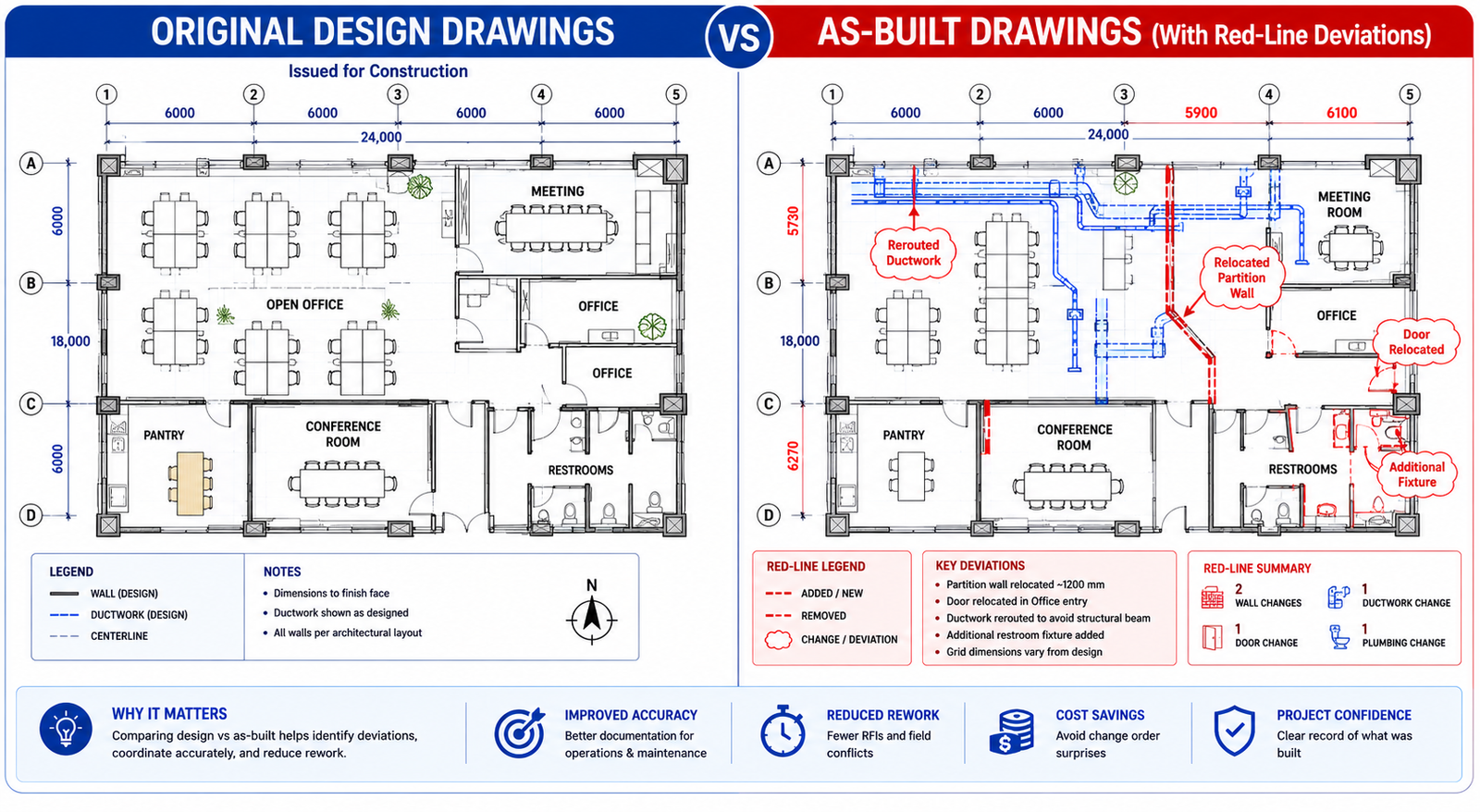
A mid-size manufacturer of industrial packaging equipment was eighteen months into a new product development cycle. The project had consumed significant internal engineering time, produced three physical prototypes, each requiring expensive rework, and was already six months behind the original launch date. When they finally brought in an external engineering design firm for a DFM (design for manufacturability) review, the outside team identified eleven design features that were unnecessarily expensive to produce and two assembly sequences that could be consolidated. The resulting redesign cut per-unit manufacturing cost by 23 percent and the remaining development timeline by four months.
This is not an exceptional outcome. It is a typical one when engineering design services are applied at the right stage of product development. What is exceptional about that company’s situation is how long they waited before bringing outside expertise in.
Engineering design services encompass a broad range of specialized capabilities: mechanical and industrial design, CAD modeling and detailing, design for manufacturability analysis, FEA and CFD simulation, value engineering, prototyping support, and full product development outsourcing. When applied strategically, they compress development timelines, reduce manufacturing costs, and prevent the expensive late-stage rework that consumes R&D budgets and delays market entry.
This guide explains exactly how each mechanism works, backs every claim with published research and market data, and gives you a practical framework for identifying where engineering design services can create the most impact for your specific development challenge.

1. The Scale of the Problem: What Product Development Really Costs
Before examining how engineering design services reduce development costs, it is worth establishing what those costs actually look like and where the largest waste occurs.
Product development costs for a new physical product range from $20,000 for a simple consumer product with established manufacturing processes to well over $1 million for complex hardware in regulated industries. The wide range reflects differences in development complexity, required certifications, tooling costs, and the number of prototype iterations needed. For most industrial, mechanical, or electromechanical products, the realistic range is $150,000 to $500,000 from concept to production-ready design.
| DATA POINT: PwC digital product development research. Digital product development is expected to increase efficiency by 19%, reduce time-to-market by 17%, and reduce production costs by 13% compared to conventional processes (PwC, cited in multiple 2025 research analyses). |
Where Development Waste Actually Occurs
Most product development cost overruns and timeline delays share common root causes. Understanding where the waste occurs is essential to understanding how engineering design services address it.
| Waste Category | Description | Typical Cost Impact | Primary Cause |
|---|---|---|---|
| Late-stage design changes | Changes to design after tooling has been committed or prototypes have been built | $10,000 – $500,000+ per significant change | Manufacturability issues not identified in design phase |
| Excess prototype iterations | Building more physical prototypes than necessary because simulation was insufficient | $5,000 – $50,000 per iteration plus time | Under-investment in simulation and analysis upfront |
| Overly tight tolerances | Specifying precision tighter than functional requirements demand | 15-40% cost increase on affected features | Design engineers specifying to what they can model, not what manufacturing requires |
| Over-engineered components | Parts designed to perform beyond requirements, adding material and complexity cost | 10-30% avoidable material cost | Lack of value engineering discipline; conservative design culture |
| Rework from drawing errors | Manufacturing errors caused by ambiguous or incorrect engineering drawings | $2,000 – $50,000+ per incident | Inadequate drafting standards, no QC review of drawings |
| Sequential development delays | Each phase waiting for the previous to complete (design finishes before manufacturing input begins) | 4-12 additional weeks per project | Lack of concurrent engineering approach |
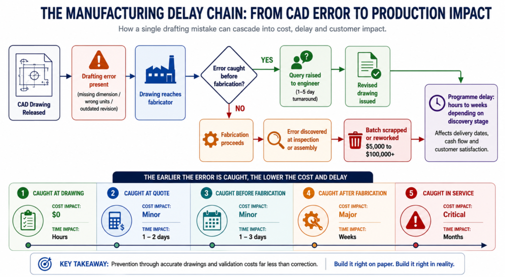
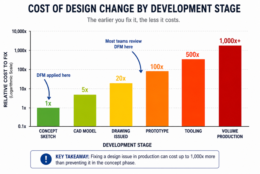
| KEY FINDING: The 70% rule. Research consistently shows that approximately 70% of a product’s total manufacturing cost is determined by design decisions made in the early engineering phase. Changes made after tooling commitment are exponentially more expensive than those made on screen. |
2. The Data: How Engineering Design Services Impact Time and Cost
The claims made about engineering design services, faster timelines and lower costs, are backed by a consistent body of research across industry reports, academic studies, and documented project outcomes. Here is what the evidence actually shows.
| Metric | Finding | Source / Context |
|---|---|---|
| Project completion time reduction | 30-50% reduction in project completion times for companies outsourcing engineering services | IDC research, cited across multiple 2025 engineering outsourcing analyses |
| Manufacturing cost reduction via DFM | 15-30% manufacturing cost reduction typical when DFM is applied early in design | Multiple DFM implementation studies; Modus Advanced, Source Engineering, SixSigma.us analyses |
| CAD software prototype cost reduction | Up to 25% reduction in physical prototype costs in some industries through advanced CAD-driven digital validation | Intelevo Research Engineering Design Software Market Report, 2025 |
| DFM assembly time reduction | 30% reduction in assembly time demonstrated in smartphone manufacturing case study through DFM implementation from initial design phase | SixSigma.us DFM implementation analysis |
| DFM ROI timeline | 15-25% ROI improvement within 12-24 months for companies implementing DFM discipline | Source Engineering DFM analysis, 2025 |
| Digital development efficiency | 19% efficiency increase, 17% time-to-market reduction, 13% production cost reduction from digital product development | PwC digital product development research |
| Engineering design software simulation savings | Organizations report cuts of up to 30% in physical prototyping costs and time savings of several weeks per project from simulation-driven workflows | Intelevo Research, Engineering Design Software Market, 2025 |
| Cost savings vs. internal hiring | Clients save 30-50% compared to hiring equivalent engineering capability internally | Engon Technologies outsourced mechanical engineering analysis |
These figures deserve honest contextualization. The 30 to 50 percent project completion time reduction is an aggregate finding that reflects well-managed outsourcing arrangements on appropriate project types. It does not mean every project becomes half as long by bringing in external engineers. The savings are most pronounced in specific scenarios: projects where specialist skills are the bottleneck, organizations with under-resourced internal engineering teams, and products where DFM has not previously been applied. The following sections explain the specific mechanisms through which these savings are generated.
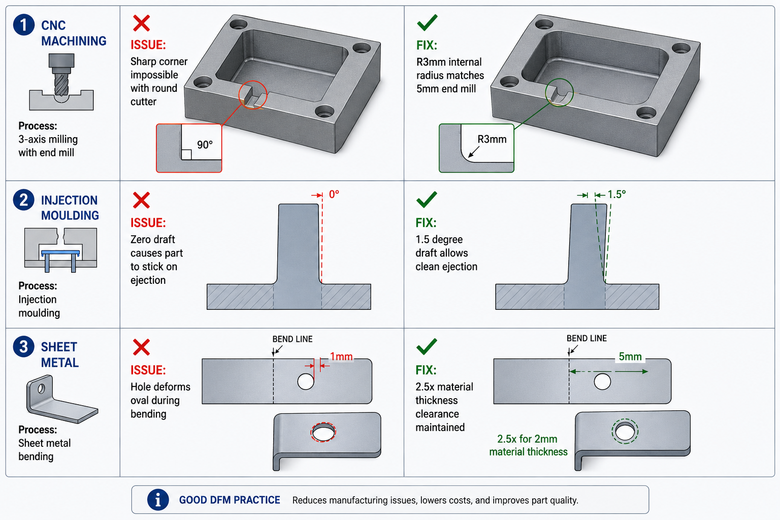
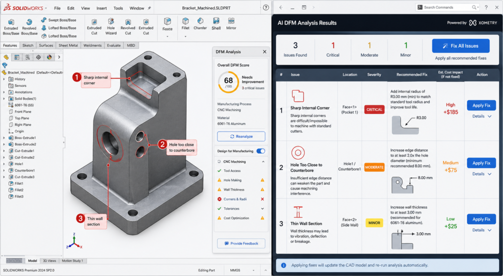
3. Mechanism 1: Design for Manufacturability (DFM) — Solving Cost Problems at the Source
Design for manufacturability is the single highest-impact mechanism through which engineering design services reduce product development cost. It is also the most consistently underused discipline in product development, particularly at small and mid-size manufacturers whose internal teams are primarily trained in design and modeling, not in manufacturing process optimization.
What DFM Actually Does
DFM is the engineering practice of designing a product to reduce the cost and complexity of its manufacture, without compromising its functional performance. It operates on a fundamental principle that is easy to state and surprisingly difficult to implement internally: the design phase is the cheapest and most powerful place to make cost decisions.
Research from multiple DFM implementation studies confirms that approximately 70% of a product’s total manufacturing cost is locked in by design decisions made before a single physical part is produced. Material selection, part geometry, tolerance specifications, assembly sequence, and component count: each of these decisions, made on screen by a design engineer, determines what a machinist, fabricator, or assembler will spend years executing.
When those decisions are made by engineers who understand manufacturing processes deeply, costs are naturally controlled. When they are made by designers optimizing primarily for function and aesthetics, manufacturing inefficiencies are designed in and discovered later, at much greater expense.
Specific DFM Cost Levers
- Tolerance rationalization: Overly tight tolerances are a pervasive and silent cost driver. A tolerance specification that requires specialized fixturing, slower machining, or 100% inspection adds cost with no functional benefit if the tolerance is tighter than the application demands. DFM review consistently finds opportunities to relax non-critical tolerances, often reducing machining costs by 20 to 40% on affected features.
- Part count reduction: Every component in an assembly adds cost: material cost, machining or molding cost, inventory cost, assembly labor, inspection, and potential failure points. DFM analysis looks for opportunities to combine functions into fewer parts. A two-part assembly that becomes a one-part assembly eliminates an entire component’s cost stack.
- Standardized hardware: Custom fasteners, specialty hardware, and non-standard materials add procurement cost and supply chain risk. DFM substitutes standard hardware wherever functional requirements permit, reducing both per-unit cost and purchasing complexity.
- Manufacturing process alignment: A design that looks manufacturable in CAD may be difficult or impossible to produce efficiently with the actual manufacturing processes available to your supply chain. DFM bridges this gap, ensuring that geometry, features, and tolerances align with what your specific manufacturing partners can do efficiently.
- Assembly sequence optimization: Assembly operations are labor-intensive and error-prone. DFM reviews assembly sequences to reduce the number of steps, eliminate orientations that require skilled judgment, and design for assembly automation where volume justifies it.
| REAL WORLD: DFM cost reduction in practice. A smartphone manufacturer integrating DFM principles from the initial design phase achieved a 30% reduction in assembly time for their latest model (SixSigma.us case study). Effective DFM implementation typically reduces manufacturing costs by 15-30% without compromising functionality, with some comprehensive programs reporting even higher savings. |
Why Internal Teams Miss DFM Opportunities
The reason DFM is underused is structural, not a matter of skill or intention. Internal design engineers are evaluated primarily on whether the product works. Their performance metrics rarely include manufacturing cost or assembly time. External engineering design service firms, whose value proposition includes manufacturability optimization, approach the same design from a different incentive structure. They are looking for cost and complexity that can be removed, not just function that needs to be preserved.
This is not a criticism of internal engineering teams. It is an observation about organizational incentive structures. The most effective approach is to ensure that DFM discipline, whether delivered internally or through an engineering design service partner, is applied before tooling commitments are made.
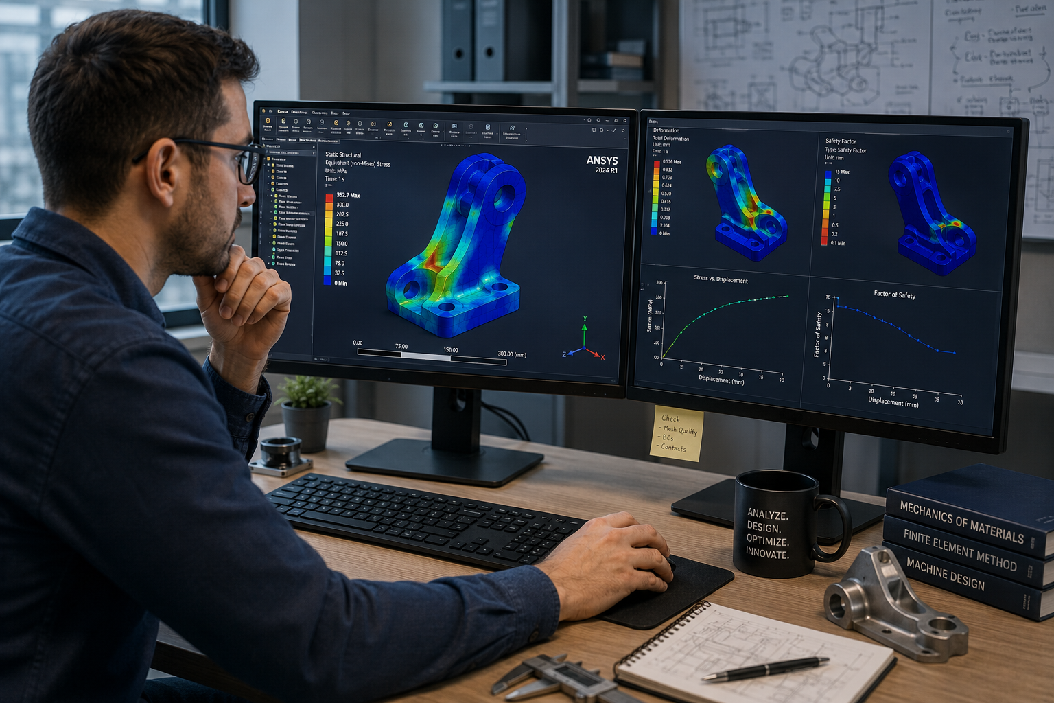
4. Mechanism 2: Expert CAD and Simulation — Fewer Prototypes, Faster Validation
Physical prototyping is expensive. A machined prototype of a moderately complex mechanical component can cost $1,000 to $10,000 and take one to four weeks to produce. An injection-molded prototype, if the mold is purpose-built, can cost $5,000 to $50,000. Complex assembly prototypes for industrial products can run $50,000 to $200,000 each. Most product development programs require multiple iteration cycles.
Engineering design services that include advanced CAD modeling, FEA (finite element analysis), and CFD (computational fluid dynamics) simulation reduce the number of physical prototypes required by validating designs digitally before physical production. The savings are substantial and well-documented.
How Simulation Replaces Physical Prototyping
FEA simulation allows engineers to apply virtual loads, stresses, temperatures, and forces to a 3D CAD model and observe how it responds, identifying failure points and optimization opportunities without building a physical part. CFD simulation models fluid flow, heat transfer, and pressure distribution for fluidic and thermal applications. Both capabilities are standard offerings of experienced engineering design service firms.
Engineering design software market research published in late 2025 documents that organizations using simulation-driven workflows report cuts of up to 30% in physical prototyping costs and time savings of several weeks per project. The mechanism is straightforward: a simulation run that takes hours replaces a prototype iteration that takes weeks.
| DATA POINT: Simulation-driven development. Organizations report up to 30% reduction in physical prototyping costs and several weeks of time savings per project when simulation-driven workflows replace or supplement physical prototyping (Intelevo Research Engineering Design Software Market Report, 2025). |
The Role of Expert CAD in Reducing Rework
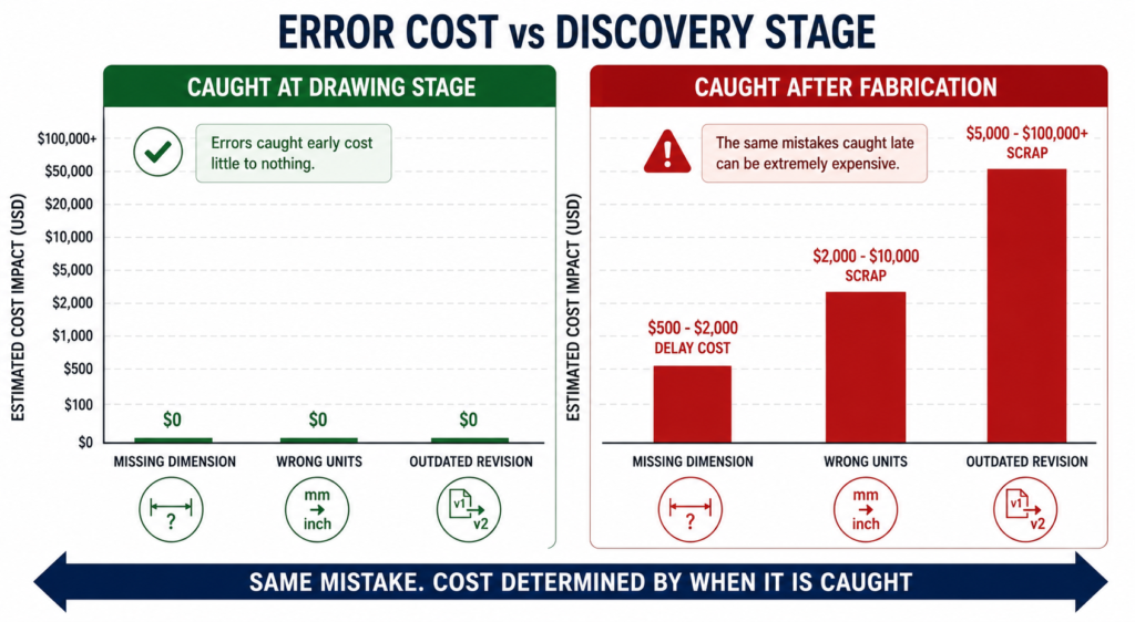
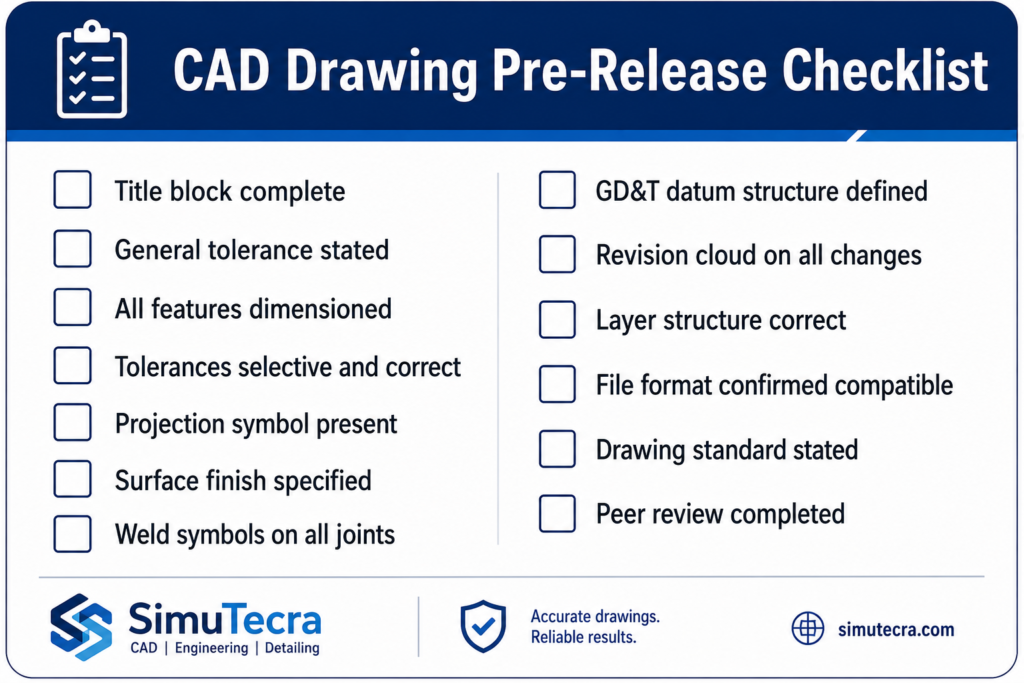
Beyond simulation, the quality of CAD modeling and drawing production directly affects downstream cost. Ambiguous drawings, incorrect tolerances, missing specifications, or drawing errors discovered during first article inspection create costly correction cycles. Engineering design service firms with experienced drafters and established QA processes produce fewer drawing errors, which translates directly to fewer manufacturing corrections and lower first article failure rates.
This is a cost savings that is invisible until you calculate what manufacturing corrections actually cost: rescheduled production runs, material waste, expedited re-delivery, and the project management time spent resolving a problem that originated on a drawing. For complex mechanical assemblies, a single undetected drawing error can cost $10,000 to $50,000 in manufacturing consequences.
Digital Twins and Their Growing Role
At the enterprise end of engineering design services, the integration of digital twin capabilities is extending the simulation advantage further. A digital twin is not just a simulation model; it is a continuously updated virtual replica of the physical product that can be used throughout the product’s lifecycle for ongoing validation, maintenance prediction, and design iteration. Established engineering design service firms offering digital twin capabilities are enabling clients to compress not just initial development cycles but ongoing product evolution cycles as well.
5. Mechanism 3: Concurrent Engineering Compressing the Development Timeline
Traditional product development follows a sequential model: concept is approved, then detailed design begins, then manufacturing planning begins, then procurement begins, then tooling is ordered. Each phase waits for the previous to complete. In a complex product development program, this sequential handoff structure can add 12 to 20 weeks of elapsed time to a development cycle that has no functional reason to be that long.
Concurrent engineering, also called simultaneous engineering, overlaps development phases so that manufacturing planning, procurement qualification, and tooling design begin while detailed engineering is still in progress. Engineering design service firms that work alongside client engineering teams facilitate concurrent engineering in ways that internal teams often cannot, simply because a client’s internal engineers are already fully occupied with the design work itself.
How It Works in Practice
An external engineering design services partner can take ownership of detailed drawing production, BOM development, and supplier qualification while the client’s internal team focuses on design decisions and customer requirement management. This parallel workflow structure removes the sequential wait times that inflate development timelines.
Research published by IDC and cited across multiple 2025 engineering services analyses finds that companies outsourcing engineering services experience 30 to 50 percent reductions in project completion times. The concurrent engineering effect is a primary driver of the upper end of this range.
DATA POINT: Concurrent engineering timeline impact. Companies outsourcing engineering services to enable concurrent workflows experience 30-50% reduction in project completion times compared to sequential internal development models (IDC research, 2025).
The Follow-the-Sun Advantage
For organizations engaging offshore engineering design service partners, the time zone difference that initially sounds like a communication challenge can become a timeline accelerator. A design change reviewed internally at 5 PM can be modeled and returned as updated drawings by 8 AM the next morning, because the engineering team in a complementary time zone was working while the client team slept. For projects on tight timelines, this follow-the-sun workflow can reduce elapsed calendar time by 15 to 25 percent on drawing-intensive phases.
6. Mechanism 4: Value Engineering — Cost Reduction Without Compromising Performance
Value engineering is a structured methodology for analyzing the function of a product, component, or process and finding ways to deliver the same function at lower cost. It is different from cost-cutting in a critical way: cost-cutting reduces cost by reducing what you do. Value engineering reduces cost while preserving or improving what the product does.
Engineering design service firms experienced in value engineering bring an external perspective that is extremely difficult to replicate internally. When your engineers have been working on a product for two years, they have cognitive ownership of design decisions that made sense when they were made. Questioning whether a part needs to be aluminum or whether a five-component assembly could be one injection-molded part requires fresh eyes and process discipline that external partners provide naturally.
Value Engineering in Action: Key Techniques
- Material substitution: Replacing an over-specified material with one that meets functional requirements at lower cost. Aluminum for steel where weight is not a concern, commodity-grade plastics for engineering polymers where chemical resistance requirements do not justify the premium.
- Process substitution: Changing the manufacturing process to one that is more cost-effective for the required quantity. Switching from CNC machining to casting for high-volume components, or from welded fabrication to bent-and-formed sheet metal for certain enclosure geometries.
- Assembly consolidation: Redesigning multi-component assemblies into single molded or formed parts. Fewer parts mean less assembly labor, fewer inventory line items, fewer potential failure points, and lower total cost.
- Standard component substitution: Replacing custom or specialty components with standard catalog items. Standard bearings, fasteners, seals, and hardware are less expensive, more reliably available, and supported by established maintenance practices.
- Tolerance optimization: Identifying and relaxing tolerances that are tighter than functional requirements. This is a DFM concept applied through a value engineering lens: every tolerance that can be relaxed reduces manufacturing cost without reducing product performance.
| INSIGHT: When to apply value engineering. The highest-value window for value engineering is during design development, before tooling commitments. Applied after tooling, value engineering still has potential, but it must work within the constraints of existing tooling geometry. Applied at the design stage, it has full freedom. |
7. Mechanism 5: Access to Specialization — Solving Problems Faster with the Right Expertise
One of the least quantified but most practically significant ways engineering design services reduce development time is by eliminating the learning curve that occurs when an internal team encounters a design challenge outside their primary expertise.
A mechanical engineering team with deep expertise in rotating equipment may spend three weeks researching best practices for designing a compliant mechanism that is new to their portfolio. An engineering design service firm that has designed fifty compliant mechanisms can solve the same problem in three days. The difference is not capability; it is accumulated domain knowledge that is not worth building internally for a one-time challenge.
Where Specialization Creates the Biggest Timeline Advantage
| Specialization Area | When It Creates Timeline Advantage | Typical Internal vs. External Timeline Difference |
|---|---|---|
| Structural simulation (FEA) | When internal team has limited simulation expertise and is iterating physically | 3-5 weeks physical vs. 3-5 days simulation |
| GD&T and tolerance stack analysis | When drawings are being returned by manufacturers due to ambiguous tolerances | Days of correction cycles vs. hours with an expert |
| Medical device design controls | When product must meet FDA 21 CFR Part 820 or ISO 13485 requirements | Months of compliance learning vs. weeks with a specialist |
| BIM coordination and clash detection | When construction project has multi-discipline coordination requirements | Weeks of manual coordination vs. days with BIM specialists |
| DFM for a new manufacturing process | When product design requires a process the internal team has not used before | Multiple prototype iterations vs. expert guidance upfront |
| Sheet metal or injection mold design rules | When designers are modeling geometry that is expensive or impossible to produce | Multiple quote rejections vs. producible geometry first time |
| ASME Y14.5 GD&T compliance | When drawings must meet standard for a defense, aerospace, or regulated client | Redline review cycles vs. correct first submission |
The market data reflects the economic value of this specialization access: the global product engineering services market was valued at approximately $1.38 billion in 2025 and is projected to grow at a compound annual growth rate of 9.7% through 2034, driven substantially by organizations accessing specialized engineering capabilities they do not maintain internally. According to Fortune Business Insights, the growing focus on faster product deliveries and time-to-market systems is a primary driver of this sustained market expansion.
8. Mechanism 6: Elastic Capacity — Scaling Without Hiring Cycles
Hiring a mechanical engineer in a competitive market takes three to six months from job posting to productive contributor. An experienced senior mechanical engineer with the specific specialization you need may take longer. During that period, your product development program either waits, proceeds with understaffed engineering resources and accepts the quality consequences, or pays premium contract rates for interim coverage.
Engineering design services provide elastic capacity: the ability to scale engineering bandwidth up or down in response to project demand without the fixed cost commitment of employment or the delays of a recruiting cycle. This elasticity directly reduces development time by ensuring that engineering bandwidth is never the bottleneck.
Where Elastic Capacity Has the Highest Impact
- Program surges: When a large contract win or accelerated launch date requires engineering bandwidth that exceeds internal team capacity, engineering design services provide immediate scale-up without a hiring cycle.
- Specialist gaps: When a specific phase of development requires expertise (BIM coordination, FEA simulation, medical device design controls) that the internal team does not maintain, engineering services fill the gap without requiring permanent headcount.
- Geographic expansion: When projects require knowledge of local building codes, regional standards, or specific regulatory environments, engineering service partners with local expertise eliminate the learning curve.
- Peak-and-valley workloads: Many product development organizations have inherently cyclical workloads: intense during design and development phases, lower during production. Engineering design services allow organizations to staff their engineering function for average load and supplement at peak, rather than staffing for peak and carrying idle capacity at valley.
| DATA POINT: Elastic capacity economics. Large enterprises dominated the product engineering services market in 2025 with 61% market share, driven by their need for flexible, scalable engineering resources that can be deployed without fixed overhead commitments (SNS Insider Market Report, 2026). |
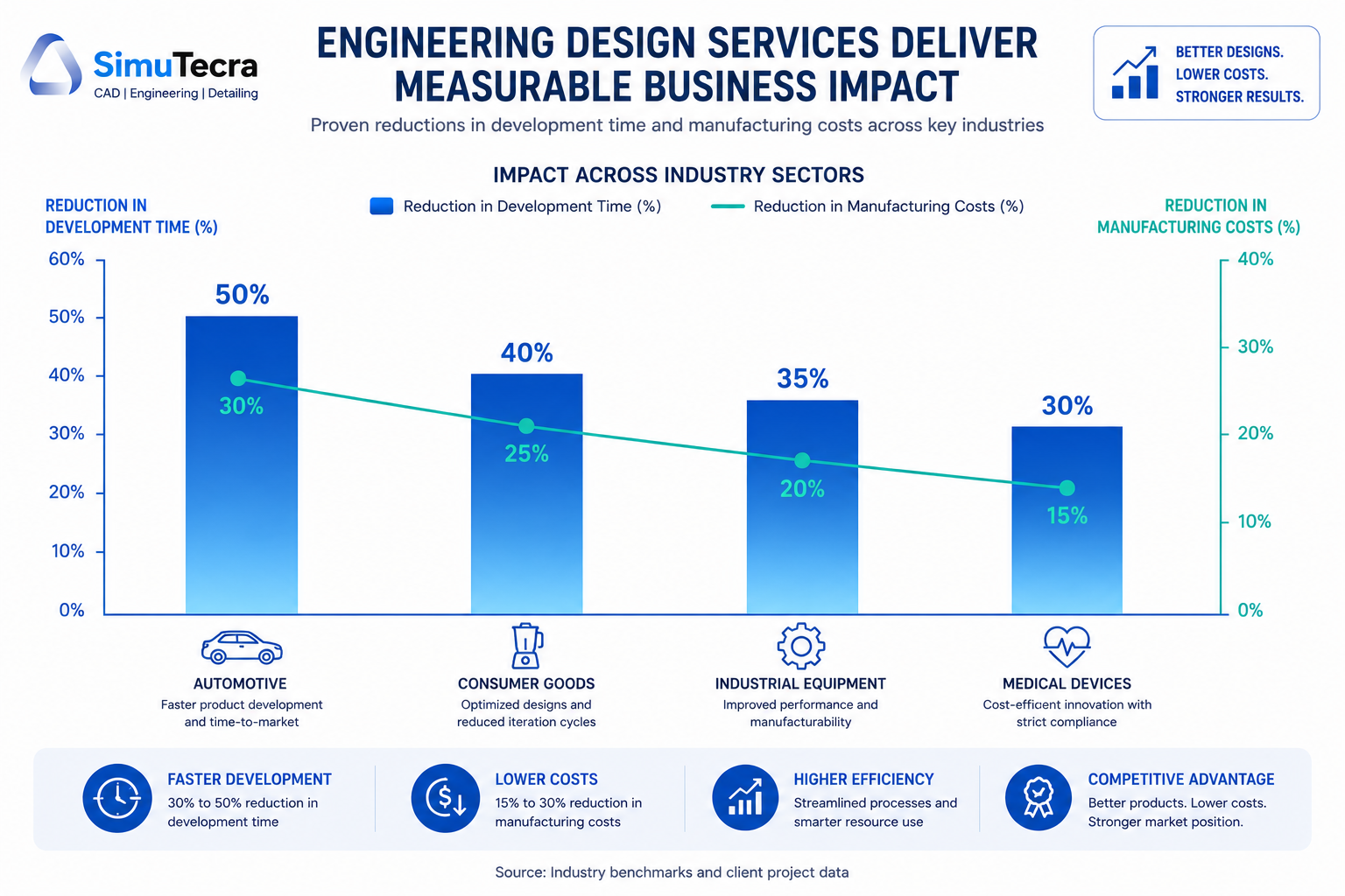
9. Industry-Specific Impact: Where Engineering Design Services Deliver the Most Value
The impact of engineering design services is not uniform across industries. The following analysis identifies where the benefits of time reduction, cost savings, and specialized expertise are most pronounced.
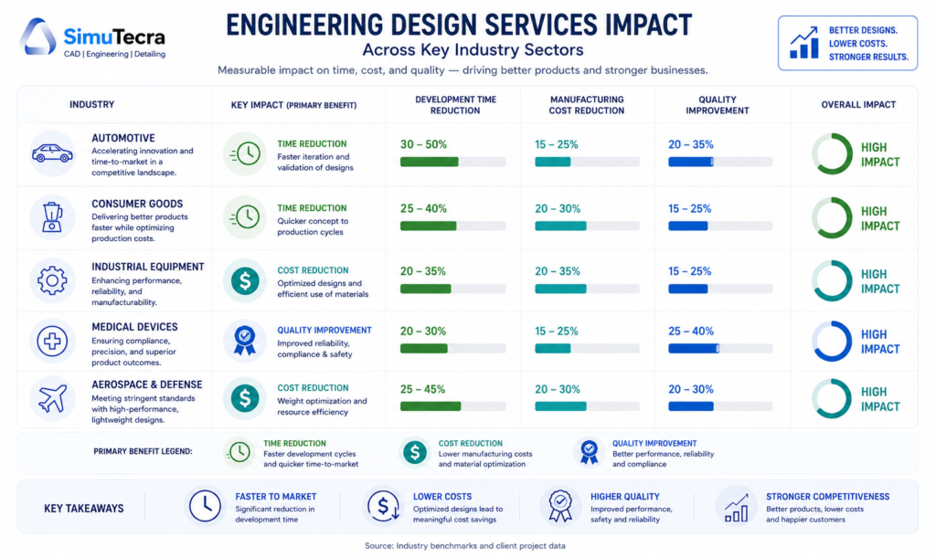
| Industry | Primary Benefit Area | Key Mechanism | Typical Outcome |
|---|---|---|---|
| Automotive and EV | Time-to-market compression | Concurrent engineering, simulation-driven design, offshore parallel workflows | 30-50% development timeline reduction; significant DFM savings at production scale |
| Medical devices | Regulatory compliance speed | Design control documentation, FDA/ISO 13485 expertise, risk management integration | Months saved in FDA submission preparation; reduced design history record rework |
| Consumer goods / CPG | Manufacturing cost reduction | DFM, value engineering, tooling optimization for high-volume production | 15-30% manufacturing cost reduction; part count reduction reduces per-unit cost |
| Industrial equipment | Specialization access | FEA/CFD simulation, mechanical system design, custom component DFM | Prototype reduction; fewer field failures from simulation-validated designs |
| AEC (Architecture, Engineering, Construction) | Drawing production speed | BIM coordination, MEP drafting, structural detailing outsourcing | Project schedule acceleration; fewer RFI and clash-driven delays |
| Aerospace and defense | Technical documentation quality | GD&T compliance, AS9100 drawing standards, configuration management | Reduced first article rejections; lower audit finding rate |
| SME manufacturers | Access to capabilities not maintained internally | Full product development outsourcing; DFM review; CAD modeling support | Access to senior engineering capability without full-time employment cost |
10. Where Engineering Design Services Do NOT Reduce Costs or Time
Intellectual honesty requires naming the situations where engineering design services do not produce the outcomes described in vendor marketing. Understanding these limits prevents misaligned expectations and poor procurement decisions.
When the Brief Is Inadequate
An engineering design service firm, however experienced, cannot produce accurate, manufacturable, cost-optimized drawings from a vague or incomplete brief. The output quality of engineering design services is directly bounded by the quality of input they receive. Organizations that engage external engineering partners without investing in clear scope definition, organized input materials, and responsive communication during execution will not see the timeline and cost benefits described in this guide. The fault will be on the client side, not the provider side, but the result is the same: wasted time and rework.
When IP Risk Is Undermanaged
For organizations with highly proprietary designs, outsourcing engineering work without proper contractual protections (work-for-hire clauses, NDAs, data handling agreements) creates IP risk that can offset the economic benefits. This does not mean outsourcing is inappropriate; it means the legal and contractual infrastructure must be established before any design files are shared. Organizations that skip this step, often because the procurement felt informal or the timeline was tight, create vulnerabilities that can be costly to resolve.
When the Work Is Too Context-Dependent
Some engineering design work is so deeply embedded in institutional knowledge, customer relationships, and ongoing system context that external partners cannot contribute effectively without a disproportionate knowledge transfer investment. If explaining the project context to an external partner would take longer than doing the work internally, the economics of outsourcing break down. This is particularly true for complex systems with years of accumulated design decisions, regulatory certifications, and customer-specific requirements.
When Cost Savings Come at the Expense of Quality
Selecting an engineering design service partner primarily on price, particularly for offshore providers at the lowest end of the market rate range, can produce drawings and models that require extensive internal correction before they are usable. The cost of that correction often exceeds the price savings from the low-cost provider. The quality of engineering design services varies significantly across providers, and the selection process must include portfolio review, standards compliance verification, and ideally a pilot project before committing to a major engagement.
| WATCH OUT: The low-cost trap. A per-sheet rate that looks 60% cheaper than market rate may result in drawings that require three rounds of redlining before they are useful. Calculate the total cost of engagement, including your internal review time, not just the provider’s quoted rate. |
11. How to Evaluate Whether Engineering Design Services Are Right for Your Project
Not every product development challenge benefits from external engineering design services. The following decision framework helps identify the scenarios where the time and cost benefits are most likely to be realized.
The High-Value Indicators
Engineering design services are most likely to reduce your development time and cost when one or more of the following conditions apply:
- Specialist skill gap: Your project requires expertise your internal team does not have. Bringing in specialists is faster and cheaper than building the skill internally for a single application.
- Capacity constraint: Your internal engineering team is already fully occupied. Adding external resources is more efficient than delaying the project or burning out internal staff on overtime.
- DFM opportunity: Your product is in design development and has not yet undergone a formal manufacturability review. The 70% rule applies: this is your best window to lock in cost-efficient design decisions.
- High prototype count: Your recent development programs have required more physical prototypes than planned. Simulation and expert design review can reduce that number on the next program.
- Cyclical workload: Your engineering demand peaks during design phases and drops during production. External services allow you to match capacity to demand rather than staffing for peak.
- Regulated environment with compliance gaps: Your product must meet FDA, AS9100, ITAR, or similar regulatory requirements that your team is not fully experienced with. External partners with compliance expertise reduce risk and timeline.
The Low-Value Indicators
Engineering design services are less likely to reduce time and cost when:
- Institutional knowledge is the primary bottleneck: If the limiting factor is deep product-specific knowledge that cannot be efficiently transferred, external engineers will spend more time learning context than producing output.
- The brief cannot be clearly defined: If the project scope is genuinely ambiguous and exploratory, an external partner working from an unclear brief will require extensive revision cycles that negate the timeline benefit.
- IP sensitivity is high and legal infrastructure is not in place: If you cannot establish appropriate contractual protections before sharing design files, the risk may outweigh the benefit.
- Volume is too low to justify onboarding: A single two-hour drafting task does not justify the time investment of briefing, standards transfer, and QC review for a new external partner. Minimum economics apply.
12. FAQ: Engineering Design Services and Product Development Efficiency
How much can engineering design services actually reduce development time?
The documented range is 17 to 50 percent, depending on project type and the specific services applied. PwC research on digital product development documents a 17 percent time-to-market reduction from digital development practices. IDC research on engineering outsourcing documents 30 to 50 percent project completion time reduction. The upper end of that range reflects concurrent engineering arrangements where external resources run in parallel with internal development, compressing the elapsed timeline. The lower end reflects more targeted applications like simulation-based prototype reduction or specialist skills engagement. Neither figure applies universally. The specific impact on your program depends on where your current development process has the most friction.
What is the most cost-effective first step when evaluating engineering design services?
For most manufacturers, a DFM review of a product that is currently in design development or has recently entered production is the highest-confidence first engagement. It is contained in scope, has a clear deliverable (a list of design changes with estimated cost impact), and the ROI is directly measurable by comparing manufacturing costs before and after implementation. A DFM review for a moderately complex product typically costs $3,000 to $15,000 and can identify cost savings of $30,000 to $150,000 or more on a product with meaningful production volume. That is a risk-justified first engagement that establishes the value of the relationship.
How do engineering design services compare to hiring internally for reducing development costs?
The cost comparison favors external services when specialization access, capacity flexibility, or time-to-market speed is the primary objective. Published analyses from engineering outsourcing practitioners show cost savings of 30 to 50 percent compared to equivalent internal hiring when fully loaded employee costs (salary, benefits, software, training, onboarding) are included. The case for internal hiring is strongest when the design work is ongoing, deeply context-dependent, requires real-time collaboration throughout the day, or involves highly sensitive IP that needs to remain within your own infrastructure. Many organizations reach the optimal outcome with a hybrid model: core engineering capability internally, supplemented by external services for specialist tasks and volume overflow.
Does outsourcing engineering design work create quality risks?
It can, if the engagement is managed poorly. The quality risks associated with external engineering design services are well-understood and manageable: inadequate brief causing misaligned output, insufficient QC review before drawings enter production, and standards compliance gaps if the provider is not familiar with your applicable standards. Organizations that establish clear drawing standards documentation, include a defined QC review step in the workflow, and vet providers on their specific discipline experience routinely achieve quality equivalent to or better than their internal baseline. The risk is real but not inherent. It is a function of process discipline, not of the outsourcing model itself.
At what stage of product development should engineering design services be engaged?
The greatest leverage is at design development, before tooling commitments. This is where DFM review, value engineering, and simulation-driven prototype reduction deliver the most impact. The 70 percent cost-determination rule makes this timing critical. After tooling is committed, value engineering and DFM still have potential, but they work within constraints that limit the available savings. At concept stage, engineering services are most valuable for feasibility analysis and technology selection. At production stage, the primary engineering service value shifts to as-built documentation, manufacturing support drawings, and process improvement analysis.
How do I measure ROI from engineering design services?
The most accessible ROI metrics are manufacturing cost per unit before and after DFM engagement, number of prototype iterations per development program, elapsed development time from design freeze to production release, first article acceptance rate, and engineering revision cycles per drawing release. For an organization new to measuring engineering design service ROI, we recommend selecting one clear baseline metric from your most recent comparable development program and tracking it against the program where engineering design services are applied. A single metric tracked rigorously tells you more than multiple metrics tracked loosely.
Conclusion:
The framing of engineering design services as a cost center, something to minimize or avoid, is the most expensive mistake organizations make in managing their product development operations. The data is consistent: applied strategically, engineering design services reduce product development costs by 15 to 30 percent, compress timelines by 17 to 50 percent, and produce ROI improvements of 15 to 25 percent within 12 to 24 months.
Those outcomes are not generated by simply hiring a cheaper external engineer to do work your internal team would otherwise do. They are generated by applying specific mechanisms, DFM, simulation-driven validation, concurrent engineering, value engineering, and specialization access, at the right stage of development, with sufficient organizational discipline to act on what those services recommend.
The 70 percent rule is the most important number in this entire discussion. Seventy percent of your product’s manufacturing cost is determined by design decisions made before a single physical part is produced. Every week you spend in design development without DFM discipline, simulation validation, and expert review is a week of cost decisions being locked in by default rather than by intent.
Engineering design services give you the ability to make those decisions intentionally, with the specialized knowledge and fresh perspective that internal teams, however capable, often cannot provide for themselves. The organizations that treat this as a strategic investment rather than an operational cost are the ones whose products consistently reach market faster, cost less to produce, and require fewer post-launch corrections.
Ready to reduce your product development time and cost?
Explore our related guides on in-house versus outsourced CAD drafting, how to write a comprehensive RFQ for engineering design services, and what CAD drafting costs in 2026 to build a complete procurement and operational framework for your engineering projects.