Tag: cad drafting

  • CAD File Formats Explained: DWG vs DXF vs STEP vs IGES and When Each Matters

    CAD File Formats Explained: DWG vs DXF vs STEP vs IGES and When Each Matters

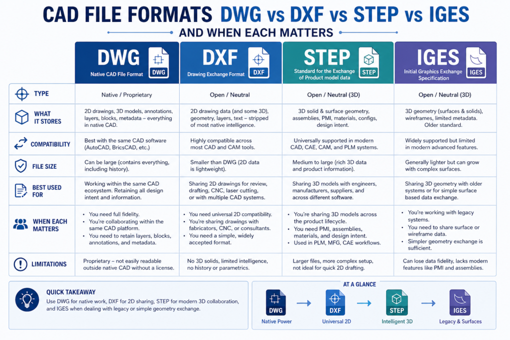
    A supplier sends back a file you cannot open. A manufacturer returns a model with geometry errors that were not in your original design. A client cannot view the drawing you emailed them. In each of these cases, there is a good chance the format was wrong, not the content. CAD file formats are one of the most misunderstood and most consequential decisions in any engineering workflow, and getting them wrong costs time at every stage of a project.

    This guide explains the most common CAD file formats, what each one actually is, what it carries, what it cannot carry, and when to use or request it. Whether you are an engineer managing a design handover, a project manager coordinating with suppliers, or a buyer receiving deliverables from a CAD partner, understanding file formats means fewer errors, fewer delays, and fewer frustrating email chains about why a file will not open.

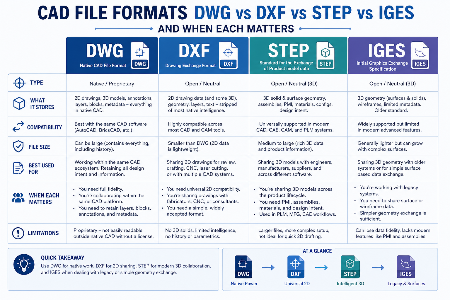
    Quick Reference: CAD File Formats at a Glance

    FormatTypeBest ForWorks WithAvoid When
    DWGNative / Proprietary2D drafting, AutoCAD workflows, drawing exchange between AutoCAD usersAutoCAD, BricsCAD, NavisworksSharing with non-Autodesk tools, compatibility issues are common
    DXFOpen Exchange2D drawing exchange across different CAD platforms and older softwareAlmost any CAD or CNC toolTransferring 3D geometry, DXF 3D support is inconsistent
    STEPOpen Neutral3D model exchange between different CAD systems, supplier collaborationSolidWorks, CATIA, NX, Creo, Fusion 360When you need full parametric feature tree, STEP is non-parametric
    IGESOpen Neutral (legacy)Surface geometry transfer, legacy systems, aerospace/defence workflowsMost major CAD platformsNew projects, STEP is the modern replacement in most cases
    STLMesh / Output3D printing, additive manufacturing, rapid prototypingAll 3D printers and slicing softwarePrecision engineering or machining, no dimensions, no tolerances
    PDFVisual ReferenceClient approvals, drawing review, non-editable distributionAny PDF viewerActive design collaboration, cannot be edited back to CAD
    CAD File Formats DWG, DXF, STEP, IGES, STL, PDF

    Why CAD File Formats Matters More Than Most People Realise

    A CAD file is not just a container for geometry. Depending on the format, it may carry, or fail to carry, parametric feature history, assembly structure, tolerances and GD&T callouts, material properties, layer information, and metadata. When a file is converted from one format to another, some of that information is always lost. The question is which information, and whether that loss matters for the next stage of the workflow.

    This is why format is a workflow decision, not just a technical preference. The right format depends on who receives the file, what they intend to do with it, and what tools they are using. A STEP file that works perfectly for a supplier machining your part tells you nothing about whether it is the right format for a client doing a design review, a 3D printing bureau producing a prototype, or a structural analyst running an FEA simulation.

    There is no single best CAD file formats. There is only the right format for the specific recipient, tool, and purpose. The most common and costly mistake in CAD file exchange is sending whatever format is convenient rather than what the downstream workflow actually requires.

    2D Drawing Formats: DWG and DXF

    DWG and DXF are the two dominant formats for 2D engineering drawings. They share a common origin, both were created by Autodesk for AutoCAD, but they serve different purposes and have meaningfully different compatibility profiles.

    DWG (.dwg) is AutoCAD’s native binary file format. It is the working format for AutoCAD and the broader Autodesk ecosystem, including Inventor, Civil 3D, and Revit in some workflows. DWG files are compact and preserve all AutoCAD-specific features: layers, blocks, line types, dimension styles, layouts, and drawing scale settings. The limitation is compatibility: while many CAD tools claim to support DWG, the format is proprietary and Autodesk updates its specification with each AutoCAD release. Files created in a newer version of AutoCAD may not open correctly, or at all, in older versions or non-Autodesk tools.

    DXF (.dxf), Drawing Exchange Format, was also created by Autodesk but as an open format, specifically to allow other CAD tools to read AutoCAD geometry. Because DXF is ASCII-based (in its standard form), it is readable by an enormous range of software including most CNC controllers, laser cutters, plasma cutters, and virtually every CAD platform on the market. It is the most universally compatible 2D format in engineering.

    2D Drawing Formats DWG and DXF CAD file formats

    DWG vs DXF: Side-by-Side Comparison

    PropertyDWGDXF
    Format typeProprietary binary format owned by AutodeskOpen ASCII or binary exchange format
    Primary useNative working format for AutoCAD and Autodesk toolsCross-platform 2D drawing exchange
    CompatibilityBest with AutoCAD family; variable with other toolsNear-universal, works with almost any CAD or CNC software
    3D supportYes, solid and surface geometryLimited, 3D data transfer is inconsistent
    File sizeCompact binary formatLarger (ASCII version); binary DXF is more compact
    Parametric dataNoNo
    When to request itYour supplier or client uses AutoCAD as their primary toolYou need to share drawings with a different CAD platform or CNC machine

    For practical purposes: if both parties are using Autodesk tools, share DWG. If the recipient uses a different CAD platform, a CNC machine, or any tool outside the Autodesk ecosystem, DXF is the safer and more reliable choice. When in doubt, send both.

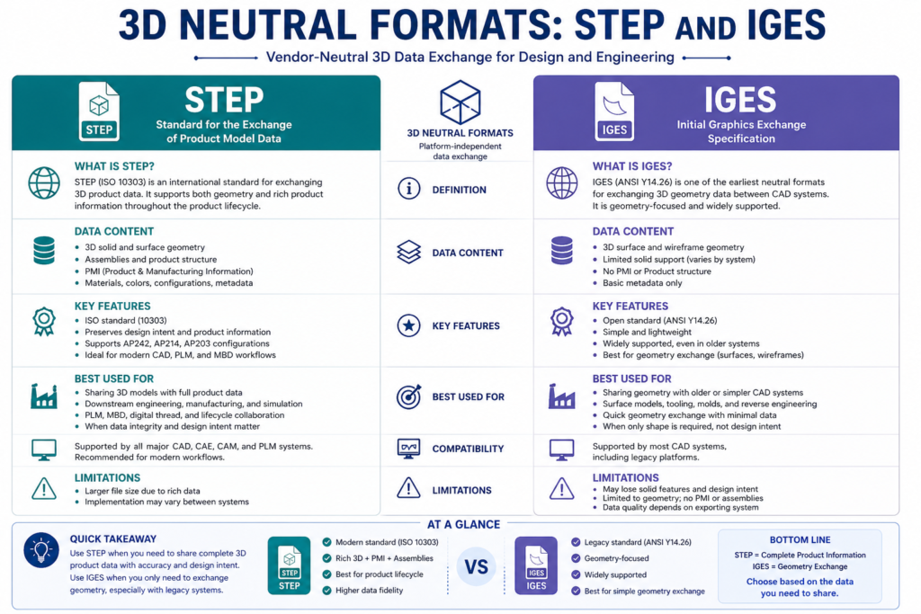
    3D Neutral Formats: STEP and IGES

    When you need to transfer a 3D model, a solid body, a surface model, or an assembly, between different CAD systems, you need a neutral format. Native CAD files (SolidWorks .sldprt, CATIA .CATPart, NX .prt, Creo .prt) are proprietary and require the originating software to open. STEP and IGES are the two dominant neutral formats that work across the industry.

    STEP (.stp or .step), Standard for the Exchange of Product model data, is the current international standard, governed by ISO 10303. It is the most widely used neutral format for 3D model exchange in manufacturing today. STEP carries solid geometry, surface geometry, and assembly structure accurately across different CAD environments. A STEP file generated in SolidWorks will open cleanly in CATIA, NX, Creo, Fusion 360, FreeCAD, or any other modern CAD platform. This is as close to a universal 3D format as the engineering industry has.

    IGES (.igs or .iges), Initial Graphics Exchange Specification, is STEP’s predecessor. Developed in the 1980s under ANSI, IGES was the dominant neutral format for decades and remains in active use in aerospace, defence, and some government procurement programmes that have not transitioned to STEP. IGES handles surface and wireframe geometry well but is less reliable for solid body transfer and often loses assembly structure on import.

    3D Neutral Formats STEP and IGES SImutecra

    STEP vs IGES: When to Use Each

    PropertySTEP (.stp / .step)IGES (.igs / .iges)
    StandardISO 10303, current international standardANSI Y14.26M, established 1980, still maintained
    Format typeNeutral open standardNeutral open standard (older)
    3D geometrySolid bodies, surfaces, assemblies, metadataSurfaces and wireframe geometry primarily
    Assembly supportYes, full assembly structure preservedLimited, assembly data often lost on import
    Parametric dataNo, geometry only, no feature historyNo, geometry only
    Industry adoptionCurrent standard, used across manufacturing globallyLegacy, still required in some aerospace and defence programmes
    Recommended forAll new 3D model exchange between different CAD systemsLegacy system compatibility or where STEP is explicitly not supported
    The most important limitation of both STEP and IGES is that neither carries parametric feature history. When a supplier or partner imports your STEP file, they receive geometry, not an editable feature tree. If future modification of the model is required, the native CAD file formats must be provided alongside the STEP. This is non-negotiable in any long-term design relationship.

    Other Formats You Will Encounter: STL, PDF, and Native Files

    Beyond the four main formats, three others appear regularly in engineering workflows and are worth understanding clearly.

    STL (.stl), stereolithography, is a mesh format that represents 3D geometry as a collection of triangular faces. It is the standard input format for 3D printers and additive manufacturing equipment. STL files carry no dimensional accuracy, no tolerances, no material data, and no parametric information, they are output files for fabrication, not engineering documents. Sending an STL to a CNC machine shop is not appropriate. Sending a STEP to a 3D printing bureau is also not appropriate unless they specifically ask for it. Each format belongs to its process.

    PDF (.pdf) is not a CAD format in the engineering sense, but it is the most widely used format for drawing distribution and approval. A 2D engineering drawing exported to PDF is universally readable, non-editable, and appropriate for client review, manufacturing reference, and project archiving. PDF should accompany every drawing deliverable, it is the human-readable record of what the CAD file formats contains. It is not a substitute for a proper CAD file formats in any active design workflow.

    Native CAD files (.sldprt, .CATPart, .prt, .ipt, etc.) are the working formats specific to each CAD platform. They contain the full parametric feature tree, design history, configurations, and all information that allows a model to be meaningfully edited. Native files should always be retained and should be requested as a deliverable alongside STEP and PDF in any outsourced CAD engagement. Receiving only a STEP from a CAD partner means any future modification requires rebuilding the model from scratch.

    Real-World Example: A Product Sent to Three Different Destinations

    A mechanical assembly is designed in SolidWorks, a housing, an internal shaft, four fasteners, and two seals. The design is complete and ready for fabrication and review. Three different destinations require the same data in three different formats.

    Destination 1: The Machine Shop
    The machinist needs to manufacture the housing and shaft. They use their own CAD tool to verify geometry and their CNC software to generate toolpaths. They request STEP for the 3D geometry and DXF for the 2D detail drawings. The STEP gives them an accurate solid body to check fit and clearances. The DXF feeds directly into their CNC controller. A PDF of the detail drawings is sent alongside as a manufacturing reference.
    Destination 2: The Client for Design Approval
    The client has no CAD software. They need to review the design, confirm dimensions, and sign off before manufacturing begins. A PDF of the general assembly drawing and a set of rendered views are sent. The client can mark up the PDF, review dimensions, and approve, without needing to install or understand any CAD tool.
    Destination 3: The 3D Printing Bureau for a Prototype
    Before committing to machined parts, a prototype of the housing is required. The 3D printing bureau requests an STL file. The SolidWorks model is exported to STL at high resolution. The bureau loads it into their slicing software, checks wall thickness and orientation, and prints. The STL carries no engineering dimensions, it is geometry only, which is all the printer needs.

    Three destinations, three CAD file formats, all from the same original SolidWorks model. The format decision was made based on the recipient’s tool and purpose, not based on what was easiest to export.

    Which CAD File Formats to Request From Your Engineering Partner

    One of the most practical questions in any outsourced CAD engagement is what file formats to specify in your brief. The answer depends on your downstream workflow. Use this as a reference when writing your CAD specification or RFQ:

    ScenarioRequest This FormatWhy
    Sending 2D drawings to a machine shopDXF or PDFDXF for CNC-ready files; PDF as a readable reference. Always send both if possible.
    Sharing a 3D model with a supplier using different CADSTEP (.step)STEP is the universal neutral format, almost every modern CAD tool imports it cleanly.
    Handing off a model for 3D printingSTL3D printers and slicing software require mesh format, not solid CAD file formats.
    Getting a design reviewed by a client or stakeholderPDFNon-editable, universally readable, no CAD software required on the client’s end.
    Collaborating with an Autodesk-based teamDWGNative format for the entire Autodesk ecosystem, no translation loss.
    Working with a legacy aerospace or defence supplierIGES or STEPCheck their specification, some legacy programmes still mandate IGES. Default to STEP otherwise.
    Receiving deliverables from your CAD partnerNative + STEP + PDFNative file for future editing; STEP for cross-platform use; PDF for approval and archiving.

    As a general rule: always request the native CAD file formats as a standard deliverable, regardless of what else you ask for. It is the only format that preserves full editability. The STEP and PDF are for distribution, the native file is for retention and future work.

    Frequently Asked Questions

    1. What is the difference between DWG and DXF?

    DWG is AutoCAD’s native binary format, compact, feature-rich, and best shared between Autodesk tools. DXF is an open exchange format originally created by Autodesk to allow other software to read AutoCAD files. DXF works across almost any CAD or CNC platform but has limited and inconsistent 3D support. For 2D drawing exchange outside the Autodesk ecosystem, DXF is the more reliable choice for CAD file formats.

    What is a STEP file and why is it the standard for 3D exchange?

    STEP (Standard for the Exchange of Product model data) is an ISO-standardised neutral file format that carries 3D solid geometry, surfaces, and assembly structure between different CAD systems without being tied to any single vendor. It is the current international default for 3D model exchange because it is widely supported, geometry-accurate, and preserves assembly relationships. Its main limitation is that it does not carry parametric feature history, the model arrives as geometry, not as an editable feature tree.

    Is IGES still used in engineering?

    Yes, but primarily in legacy and regulated environments. IGES (Initial Graphics Exchange Specification) predates STEP and was the dominant neutral format for decades. It is still required by some aerospace, defence, and government programmes that have not migrated to STEP. For new projects with no legacy system constraint, STEP is the better choice, it handles solid geometry and assemblies more reliably than IGES. CAD file formats

    Can I convert a STEP file back to native CAD with full parametric features?

    No. STEP files carry geometry, solid bodies and surfaces, but not parametric feature history. When a STEP file is imported into SolidWorks, CATIA, or any other parametric CAD tool, it arrives as a dumb solid: you can modify it by pushing and pulling faces, but you cannot access the original feature tree, sketches, or design intent. If you need a fully editable parametric model, you need the native CAD file formats from the originating software.

    What CAD file formats should I ask for from my engineering partner?

    For a complete and future-proof deliverable, request three formats: the native CAD file formats (in whatever software was used, SolidWorks .sldprt, CATIA .CATPart, etc.) for future editing; a STEP file for cross-platform 3D exchange; and a PDF of all 2D drawings for approval, archiving, and manufacturing reference. For 2D-only work, request DXF alongside the PDF as a CAD file formats.

    What is the difference between STL and STEP?

    STEP is an engineering format that represents precise solid geometry, it is accurate to the mathematical definition of the model and suitable for manufacturing. STL is a mesh format that approximates surfaces with triangles, it loses precision and carries no dimensional, tolerance, or material information. STL is used exclusively for 3D printing and additive manufacturing. Never send an STL to a machine shop expecting CNC-accurate results for CAD file formats.

    The Bottom Line

    CAD file formats are not a technical afterthought. They are a workflow decision that determines whether the right information reaches the right person in a form they can actually use. DWG and DXF carry 2D drawings. STEP carries 3D geometry between different CAD systems. IGES serves legacy and regulated environments. STL serves additive manufacturing. PDF serves human review and archiving. Native files serve future editability.

    The teams that get this right specify formats at the start of a project, in the brief, in the RFQ, in the supplier specification, not after a file arrives in a format no one can open. If you are outsourcing CAD work or receiving deliverables from an engineering partner, building a clear CAD file formats requirement into your specification is one of the simplest ways to prevent delays that have nothing to do with the quality of the design itself.

    Getting the Right Files the First Time
    At Simutecra CAD Drafting Services, every deliverable is packaged in the formats your team actually needs, native CAD files for editing, STEP for supplier exchange, and fully detailed PDFs for manufacturing reference and approval. We confirm file format requirements at the start of every project, not after the work is done.Tell us about your project and we will advise on the right format package for your workflow and manufacturing partners.
    Reach out to us today, Simutecra
  • How to Read Engineering Blueprints: A Practical Guide for Non-Engineers

    How to Read Engineering Blueprints: A Practical Guide for Non-Engineers

    A set of engineering blueprint drawings lands on your desk. You need to review them, approve them, or pass them to a fabricator. But the sheets are covered in symbols, numbers, dashed lines, and abbreviations that make no immediate sense. You are not alone, and this is not as complicated as it looks.

    Learning how to read engineering blueprints is a practical skill anyone can develop. You do not need an engineering degree to understand what a drawing is communicating. You need a clear framework for where to look and what each element means. This guide walks you through that framework in plain language, step by step.

    What is Engineering Blueprint?

    An engineering blueprint drawing is a technical document that communicates the exact geometry, dimensions, materials, tolerances and manufacturing requirements of a part or assembly. The name comes from the blue-tinted prints used in the 19th and 20th centuries. Today it refers to any formal technical drawing, whether printed or digital.

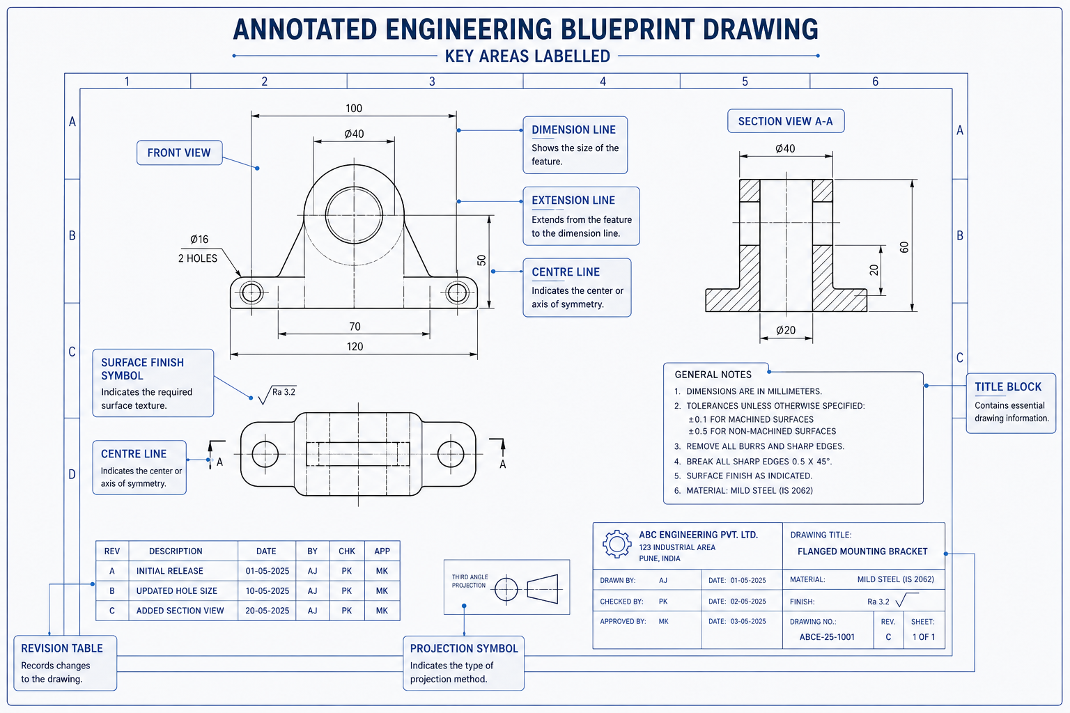
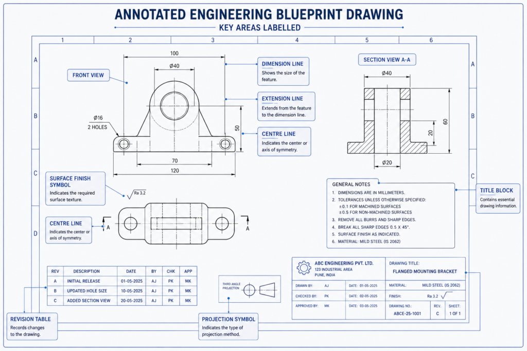
    Annotated Engineering Blueprint Drawing with Key Areas Labelled

    Step 1: Always Start with the Title Block

    Before you look at a single line of geometry, go to the title block. It sits in the bottom-right corner of every engineering blueprint drawing, in every industry, on every sheet. It is the drawing’s identity card. Everything else you read on the sheet depends on confirming this information first.

    Title Block FieldWhat It ContainsWhy Check It First
    Drawing TitleThe name of the part, assembly or system being drawnConfirms you have the right drawing for your project
    Drawing NumberA unique identifier in the document control systemUse this in all correspondence and purchase orders
    Revision LevelA letter or number such as Rev A, Rev B, or Rev 3Outdated revisions cause manufacturing errors
    ScaleThe ratio between drawing size and actual part sizeTells you whether dimensions can be read visually
    UnitsMillimetres, inches, or other unit systemMixing metric and imperial is a costly mistake
    DateWhen the drawing was created or last revisedCross-reference with your project timeline
    Drawn By / Approved ByNames and signatures of drafter and approving engineerConfirms the drawing went through a review process
    Company / ClientOrganisation that produced or commissioned the drawingConfirms which standards and formats apply

    Watch out:  The single most common and costly mistake when working with engineering drawings is using an outdated revision. Before reviewing any drawing in detail, confirm the revision level matches your project’s current issued document register. A drawing that looks fine might be three revisions behind the current design.

    Also in the Title Block: The Projection Symbol

    Look for a small symbol near the title block that shows a truncated cone viewed from two angles. This tells you which projection standard the mechanical engineering blueprint uses.

    • Third-angle projection (circle on the left, cone tip pointing right): Used in the United States, Canada, and Australia. Each view is placed on the same side as the direction you are looking from.
    • First-angle projection (circle on the right, cone tip pointing left): Used in Europe, Asia, and most of the rest of the world. Each view is placed on the opposite side to the direction you are looking from.

    Important:  If you read a first-angle drawing as if it were third-angle (or vice versa), the views appear mirrored. This leads to parts being built with holes, features, and interfaces in the wrong positions. Always check the projection symbol before reading the views.

    Step 2: Understand How the Views Work

    Engineering drawings show a 3D object as a series of flat 2D views, like photographs of the part from different directions. The standard set is a front view, a top view, and a side view. Together, these three views define the complete shape of the part.

    Think of it this way. If you placed a part inside a glass box and drew what you could see through each face, then unfolded the box flat onto paper, you would have an orthographic drawing. Each face of the box becomes one view on the sheet.

    View NameWhat It ShowsPosition on Sheet
    Front ViewThe most descriptive face of the part, chosen to show the most geometryCentre-left of the drawing sheet
    Top ViewLooking directly down onto the partDirectly above the front view
    Right Side ViewLooking at the right side of the partTo the right of the front view (third-angle)
    Section ViewA cut-open view showing internal geometry that would be hiddenAnywhere on sheet, labelled e.g. Section A-A
    Detail ViewAn enlarged view of a small or complex area at a larger scaleAnywhere on sheet, labelled e.g. Detail B
    Isometric ViewA 3D-like pictorial view showing length, width and depth, for referenceUsually top-right corner, marked NOT TO SCALE

    Tip:  When you first open a drawing sheet, identify all the views before you read any dimensions. Trace how each view relates to the others. The front view drives the layout and the other views align to it. Understanding this spatial relationship is the foundation for reading the rest of the drawing correctly.

    Step 3: Decode the Lines and Dimensions

    Not all lines on a mechanical engineering blueprint are the same. Each line type has a specific meaning, and misreading them is one of the most common errors for people new to technical drawings.

    Line TypeAppearanceWhat It Means
    Visible (object) lineSolid, thick continuous lineA real edge visible in this view. The actual boundary of the part.
    Hidden lineMedium-weight dashed lineA real edge that exists but is hidden behind another feature in this view.
    Centre lineThin alternating long-short dashThe axis or centre of a circular feature such as a hole or bore. Not a physical edge.
    Dimension lineThin line with arrowheads at each endIndicates the distance being measured. The value sits above or within the line.
    Extension lineThin line from part edgeConnects the part geometry to the dimension line and shows what is being measured.
    Section/cutting planeThick dash-dot line with arrowsShows where an imaginary cut is made for a section view. Arrows show viewing direction.
    Phantom lineThin long-short-short dashShows adjacent parts, alternate positions or motion paths. Not part of the actual component.
    Break lineThin wavy or zigzag lineIndicates a portion of the part has been omitted from the drawing to save space.

    Reading Dimensions

    Dimensions tell the manufacturer the exact size of every feature. Here are the main types you will encounter on any engineering blueprint drawing:

    • Linear dimensions: Straight-line measurements between two points, shown with a dimension line and a value. The most common type.
    • Angular dimensions: Measurements of angles between two surfaces or lines, shown in degrees.
    • Diameter dimensions: Shown with the diameter symbol (a circle with a diagonal line through it) before the number. Always applies to circular features.
    • Radius dimensions: Shown with R before the number. Applies to arcs, fillets and rounded corners. Measured from centre to edge.
    • Depth dimensions: Shown with a downward arrow symbol. Common on hole callouts to specify how deep the hole goes.

    Tolerances on Dimensions

    Dimensions carry tolerances, which are the allowable variation from the stated value. You will see these in three main forms:

    • Plus/minus values: For example, 25.00 plus or minus 0.10 means the finished dimension can be anywhere from 24.90 to 25.10.
    • Limit dimensions: The upper and lower limits are stated directly, such as 25.10 / 24.90.
    • GD&T controls: Feature control frames that define geometric variation in addition to or instead of size tolerances.

    Important:  Never measure directly off a printed engineering blueprint drawing to determine dimensions. Drawings are not printed at a guaranteed 1:1 scale and even minor printing variation makes direct measurement unreliable. Always read the dimension value written on the drawing.

    Step 4: Read the Engineering Blueprint Symbols, Notes, and Callouts

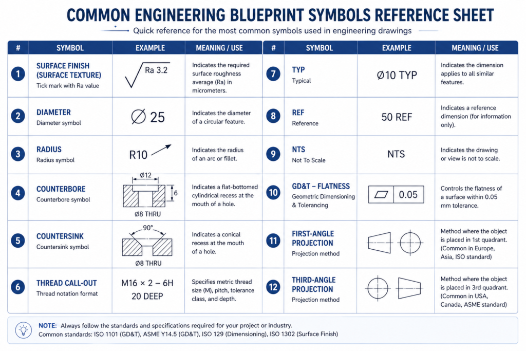
    Beyond dimensions and views, engineering blueprint symbols communicate requirements that would take several lines of text to describe in words. Knowing the most common ones means you can scan a drawing and understand what is being asked of the manufacturer without needing to ask an engineer to translate every callout.

    Symbol / NotationLooks LikeWhat It Means
    Surface finishTick mark with a number (Ra value)How smooth a surface must be. Ra 1.6 is smoother than Ra 6.3. Applies to mating and sealing surfaces.
    DiameterCircle with diagonal line before numberThe feature is circular. This is the full width through the centre, not the radius.
    RadiusR before a numberHalf the diameter. Used for arcs, rounded corners and fillets.
    CounterboreStepped circle symbolA larger flat-bottomed hole above the main hole. Used to recess bolt heads flush with the surface.
    CountersinkAngled V symbolA conical recess at the top of a hole for a flush countersunk screw head.
    Thread calloute.g. M12 x 1.75 or 1/2-13 UNCSpecifies the thread size, pitch and type for holes or external threads such as bolts and studs.
    TYP (Typical)Written after a dimension valueThis dimension applies to all identical features unless otherwise noted, not just the one it points to.
    REF (Reference)Written in brackets: (50) or 50 REFFor reference information only. Not to be used for inspection or manufacturing.
    NTS (Not to Scale)Written below a dimension or viewThis view or dimension is not drawn proportionally. Read the written number, do not measure visually.

    The General Notes Section

    Look for a notes section on the drawing, usually in the upper-left corner or near the title block. General notes apply to the entire drawing and cover things that cannot be expressed graphically: default tolerances for features without individual dimensions, surface treatment requirements, material standards, heat treatment specs, inspection requirements, and applicable regulatory or industry standards.

    A critical rule:  When a general note conflicts with a specific dimension or symbol shown on the drawing, the specific instruction takes precedence. The general note applies only where nothing more specific has been stated.
    Common Engineering Blueprint Symbols Reference Sheet

    Engineering Blueprint Examples: What You Actually See and What It Means

    Reading engineering blueprints is much easier when you have seen real examples of common callouts and know exactly what action to take. The table below covers the situations you are most likely to encounter when reviewing a mechanical engineering blueprint as a non-engineer.

    Think of this as a translation guide. Left column is what the drawing shows. Middle column is what it actually means. Right column is what you should do as the reviewer.

    What You See on the DrawingWhat It MeansWhat You Should Do
    50 +0.0 / -0.2 next to a circleA hole with diameter 50mm, but it can be 49.8mm minimum. The plus side has zero tolerance.This is a precision hole. Flag to the engineer if the tolerance seems tighter than usual for the application.
    M8 x 1.25 inside a circle with arrowAn M8 metric threaded hole with 1.25mm thread pitchConfirm the correct bolt or stud is specified in the BOM. Thread size must match the fastener.
    Dashed rectangle inside a solid outlineA hidden internal pocket or cavity not visible in this viewDo not assume the part is solid. Check the section view to understand the internal geometry.
    Section A-A with a line and arrowsA cut has been made along this line. Section view A-A shows what is inside.Find the section view labelled A-A on the sheet or on the referenced sheet.
    Ra 1.6 on a surface edgeThat surface must be machined smooth to 1.6 microns average roughnessSmoother surfaces cost more to machine. Verify this is genuinely required for the application.
    (75) in brackets near a dimensionThis is a reference dimension only. Not used for inspection.Do not use this number for manufacturing or checking. It is informational only.
    REV C in the title blockThis is the third revision of the drawingCheck your document register. Confirm Rev C is the currently issued version before proceeding.

    Real-World Example: Reviewing a Structural Steel Fabrication Package

    You are a project manager reviewing a structural steel fabrication drawing package before issuing it to a fabricator for pricing. You are not a structural engineer, but you need to confirm the package is complete and ready to issue.

    Here is exactly what you do:

    1. Confirm every sheet carries the same revision level. A mixed-revision package is a fabrication risk. If sheet 1 says Rev C and sheet 3 says Rev B, stop. Do not issue until the engineer confirms which sheets are current.
    2. Confirm the title block on each sheet references the correct project number and part descriptions. Mislabelled sheets cause real problems at a fabrication shop.
    3. Scan for revision clouds. These are the cloud-shaped borders around changed areas. If a revision cloud exists, check the revision table to confirm the change has been documented and signed off.
    4. Check for any RFI notations or open queries. An RFI marker means a question has been raised that has not been answered. Do not issue to fabrication with open RFIs.
    5. Confirm units are consistent across all sheets. If the drawing set uses millimetres throughout, every sheet should say mm. A single sheet using inches in a metric package causes manufacturing errors.

    You do not need to verify every dimension or tolerance callout. That is the engineer’s role. Your job is to confirm the package is administratively complete, internally consistent, and shows no outstanding issues before it leaves your hands.

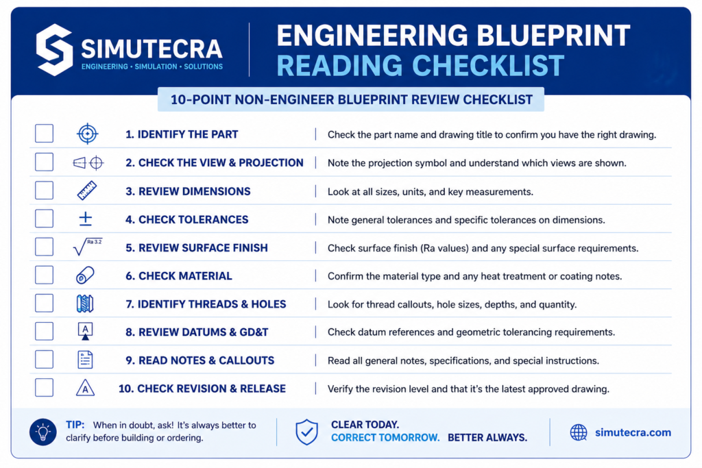
    The Non-Engineer Blueprint Review Checklist

    Use this checklist every time a drawing set arrives for review, approval, or issue to a supplier. You do not need engineering expertise to complete it. These ten checks catch the administrative and structural problems that cause the most expensive mistakes downstream.

    Engineering Blueprint Reading Checklist Visual
    What to CheckWhy It Matters
    ☐  Confirm the revision level matches your project document registerOutdated drawings cause manufactured parts that do not match current design intent
    ☐  Verify the drawing number and title match the expected part or assemblyMislabelled drawings get issued to the wrong supplier or used for the wrong job
    ☐  Check that units are stated and consistent across all sheetsMetric/imperial confusion is one of the most costly errors in manufacturing
    ☐  Identify the projection method (first-angle or third-angle)Misreading the projection direction produces mirrored or inverted parts
    ☐  Confirm all views are present and labelled with section references matchingMissing or misreferenced views leave geometry undefined or ambiguous
    ☐  Scan for revision clouds. Have all flagged changes been resolved?Unresolved revision clouds indicate the design is not yet finalised
    ☐  Check for any RFI notations or open queries on the drawingOpen RFIs mean unresolved questions. Do not issue to fabrication.
    ☐  Confirm the general notes section is present and legibleMissing notes leave default tolerances, surface treatments and material specs undefined
    ☐  Verify the drawing has been signed or approved in the title blockUnapproved drawings have not been through a design review. Issuing them is a risk.
    ☐  Check the scale is stated and marked NTS where applicableUnstated or incorrect scale creates confusion about whether dimensions can be read visually

    External Resource:  For the international standard that governs engineering drawing practice, see ISO 128 (Technical Drawings: General Principles of Presentation) published by the International Organization for Standardization at iso.org. This is the foundational standard that defines line types, projection methods, and drawing conventions referenced in this guide.

    The Bottom Line

    Reading engineering blueprints does not require an engineering degree. It requires knowing where to look, what each element means, and what questions to ask when something is missing or unclear.

    The title block tells you what you are looking at and whether it is current. The projection symbol tells you how to read the views. The line types tell you what is real geometry and what is reference information. The engineering blueprint symbols and dimension callouts tell the manufacturer exactly what to build. The general notes fill in the requirements that cannot be shown graphically.

    Together, these elements give you enough information to review a mechanical engineering blueprint confidently, catch the issues that matter, and communicate clearly with the engineers and fabricators involved. The checklist in this guide covers the ten checks that catch the majority of drawing-related problems before they reach the shop floor. Use it every time a drawing set crosses your desk.

    Know where to look. Read what it says. Ask when something is missing.

    Working With Engineering Drawings and Need Support?
    Whether you need a new drawing set produced, an existing one reviewed and updated, or a legacy drawing converted to current CAD standards, SimuTecra’s team handles the full range of engineering drafting work. Every drawing we produce is structured to be read correctly the first time.
    Send us your project details and we will come back with a clear scope and timeline.
    Reach out to us today, Simutecra

    Frequently Asked Questions

    What is an engineering blueprint?

    An engineering blueprint is a technical drawing that communicates the exact dimensions, materials, tolerances and features of a part or assembly to a manufacturer. Today the term covers both traditional blue-line prints and modern CAD-produced engineering drawing blueprints. The purpose is the same: give the maker everything needed to build the part correctly the first time.

    What is the difference between first-angle and third-angle projection?

    Both methods show the same three views of a part but arrange them differently on the sheet. In third-angle projection (used in the US, Canada and Australia), each view is placed on the side you are looking from. In first-angle projection (used in Europe and Asia), each view is placed on the opposite side. A small projection symbol in the title block tells you which method is used. Reading one as the other produces mirrored parts.

    What does NTS mean on an engineering drawing?

    NTS stands for Not to Scale. It means the feature or view is not drawn at a reliable proportion. When you see NTS, always use the written dimension value and never try to measure the feature visually off the sheet.

    How do I know which dimension takes priority if values conflict?

    Specific dimensions shown directly on the drawing geometry always override general notes. If two dimensions appear to conflict with each other, that is a drawing error. Raise it as an RFI (Request for Information) and do not send the drawing to fabrication until the discrepancy is resolved in writing.

    What is a revision cloud on an engineering drawing?

    A revision cloud is a curved, cloud-shaped border drawn around an area that changed from the previous revision. It is a visual flag so reviewers can quickly spot what is new. The change is also recorded in the revision table with the revision letter, a brief description and the date.

    Do I need to understand GD&T symbols to review an engineering blueprint drawing?

    For an administrative review covering revision level, completeness and approval status, no. For a more thorough technical review, a basic understanding of GD&T helps you confirm that critical tolerances are properly specified. Our separate guide on GD&T covers the symbols in detail if you need to go further.

  • Building an AI Pipeline for CAD + Simulation Using Prompts | Simutecra

    Building an AI Pipeline for CAD + Simulation Using Prompts | Simutecra

    The Problem: Your Design and Simulation Stages Are Still Disconnected

    Here’s a situation most mechanical engineers know well. You finish a CAD model, export the geometry, hand it to a simulation analyst (or switch tools yourself), spend half a day setting up the mesh and boundary conditions, run the solver overnight, get results that point to a design change, and then go back to the beginning.

    That cycle, design, export, setup, simulate, revise, is slow. It was designed for a world where simulation was expensive and rare. But in 2026, simulation tools are faster and AI is everywhere. The bottleneck isn’t the solver anymore. It’s the AI CAD pipeline connecting everything together.

    What engineers actually need is an AI-driven engineering pipeline, a connected sequence of intelligent tools and prompts that carries a design from concept through CAD modelling, FEA or CFD setup, results interpretation, and documentation without the constant manual handoffs that kill momentum.

    That’s exactly what this guide builds. Step by step. With real prompts you can use today.

    3
    hrs/daysaved on average
    Industry benchmarks for 2026 show that integrating AI into the CAD-to-simulation workflow saves engineers an average of 3 hours per day, reclaimed from manual data extraction, repetitive setup, and documentation (Energent.ai, 2026).
    94.4%
    AI accuracy
    Leading AI data agents now achieve up to 94.4% accuracy when reading complex unstructured engineering documents and schematics, dramatically reducing downstream specification errors.

    What an AI Pipeline for CAD and Simulation Actually Looks Like

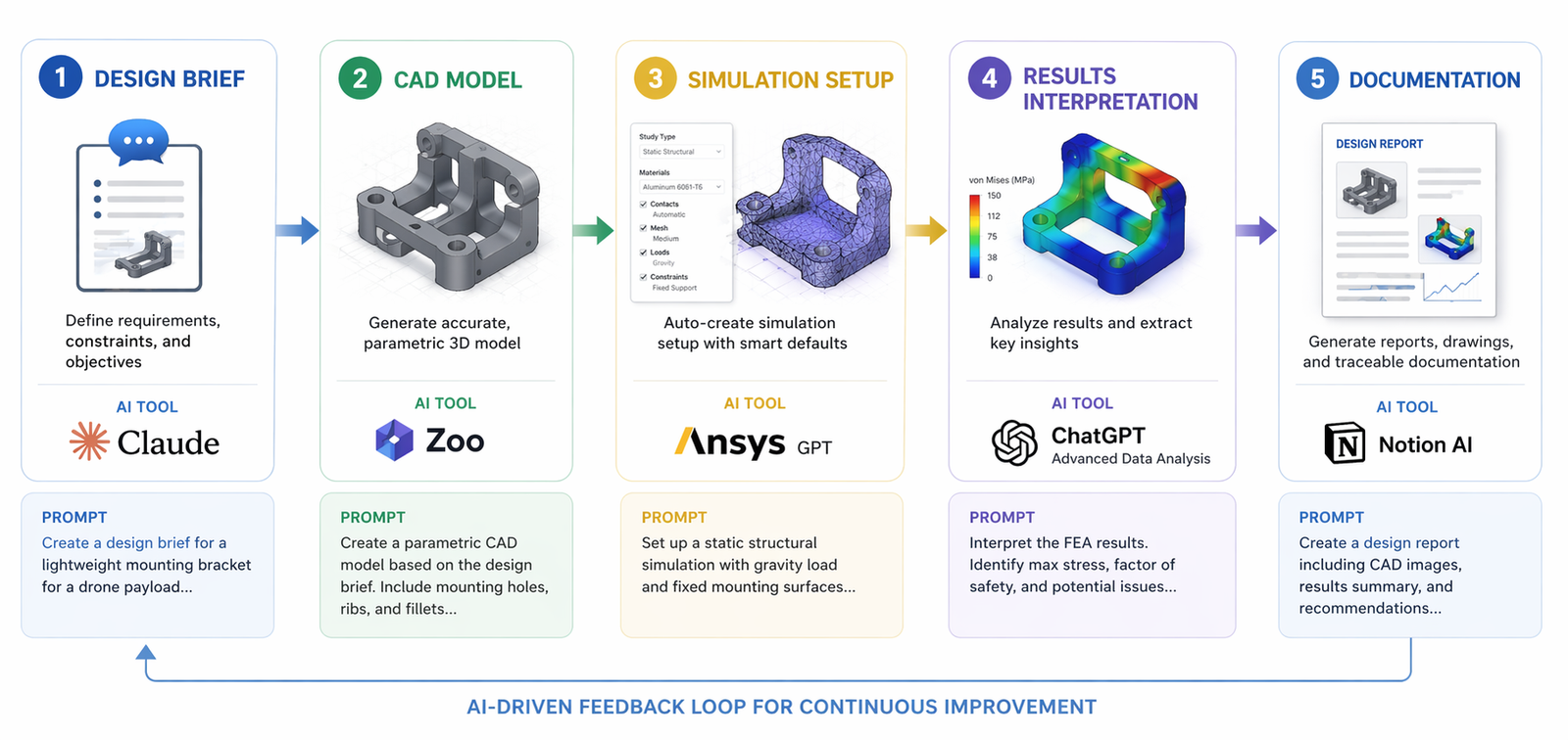
    Before building one, it helps to have a clear mental model. An AI pipeline for CAD and simulation is not a single tool, it’s a chain of connected AI interactions, each stage feeding the next with better, more specific information.

    Think of it like a relay race. The first runner (your LLM for engineering design) carries the design intent. The second (your CAD tool or text-to-CAD platform) turns that intent into geometry. The third (your FEA or CFD solver with AI setup) validates the geometry against physics. The fourth (your AI interpretation layer) tells you what the results mean and what to change. The baton never drops. The pipeline keeps moving.

    What makes this different from just ‘using AI tools’ is the prompt-based CAD workflow that threads through every stage. Prompts aren’t just for chatting, they’re the connective tissue of the pipeline. The right prompt at each stage ensures the output of one tool becomes a clean, usable input for the next. That’s what CAD simulation using prompts actually means in practice.

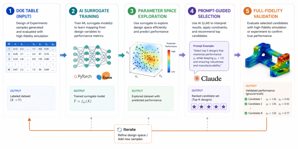
    AI pipeline for CAD and simulation using prompts 5-stage flow diagram mechanical engineering 2026

    The Four Roles Prompts Play in the Pipeline

    Understanding how prompts function at each stage clarifies why prompt engineering for design and simulation is worth learning deliberately, not just picking up informally.

    • Prompt as brief: At the design stage, a structured prompt is your engineering requirements document, it captures loads, materials, constraints, and manufacturing intent in a format AI tools can act on directly.
    • Prompt as translator: Between CAD and simulation, a prompt converts geometry decisions into AI prompts for FEA and simulation, boundary conditions, mesh guidance, load cases, and solver settings expressed in clear language.
    • Prompt as analyst: After simulation, a prompt frames your results for AI interpretation, ‘This stress concentration is at the fillet. What does that indicate and what geometry change would address it?’
    • Prompt as documenter: At the close of the pipeline, a prompt generates technical reports, design summaries, and revision notes automatically, closing the AI design loop cleanly.

    How to Build an AI CAD Simulation Pipeline, The 5 Stages

    Here is how to build a working AI pipeline for CAD and simulation using prompts. Each stage includes the tool stack, the prompt structure, and what to hand forward to the next stage. These aren’t theoretical, they’re the practices that effective AI simulation workflow teams are using in 2026.

    1. Design Brief, Define Intent Before You Touch the Software
    Most pipeline failures start here. Engineers open CAD immediately and start modelling before the requirements are precise. An AI-driven pipeline starts with a structured brief that captures everything the downstream stages need: geometry constraints, loads, materials, manufacturing method, and success criteria.
    Prompt, Stage 1 Design Brief (use with Claude AI):
    “You are a senior mechanical engineer. I need to design [part description]. Loads: [specify]. Material: [specify]. Manufacturing: [specify, e.g. CNC aluminium]. Key constraints: [tolerances, fits, standards]. Output a structured engineering brief with: (1) critical dimensions to define, (2) primary failure modes to simulate, (3) recommended simulation type (FEA/CFD/thermal), (4) suggested boundary conditions.”

    Keywords active: Claude AI engineering prompts · LLM for engineering design · prompt-based CAD workflow
    2. CAD Modelling, Geometry From Your Brief
    Take your Stage 1 brief directly into your CAD or text-to-CAD tool. The brief is already formatted in the way AI geometry tools work best: specific, dimensioned, and constraint-aware. This is where connecting CAD to simulation with AI begins, the model you build now must be simulation-ready from the start.
    Prompt, Stage 2 CAD Model (use with Zoo, AdamCAD, or SolidWorks + Claude):
    Based on this engineering brief: [paste brief from Stage 1]. Generate a [STEP / parametric feature list / AutoLISP script] for this part. Ensure all simulation-critical features, fillets, contact surfaces, load application areas, are explicitly defined. Flag any geometry that may require simplification before meshing.”
    Keywords active: connecting CAD to simulation with AI · Zoo text-to-CAD pipeline · CAD AI prompts
    3. Simulation Setup, The Bridge Most Engineers Get Wrong
    This is the stage where most manual pipelines collapse. Moving a CAD model into FEA or CFD correctly requires specialist knowledge of meshing, boundary conditions, and solver settings. AI FEA automation now handles the bulk of this, but only if you feed it well-structured prompts.
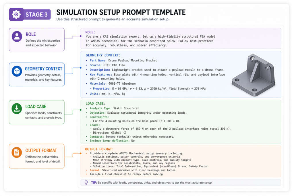
    Prompt, Stage 3 Simulation Setup (use with SimScale AI, Ansys, or Claude for setup notes):
    “I have a [material + geometry description] part. Load case: [describe loads and constraints]. I need to set up a [static structural / modal / CFD] simulation. Output: (1) recommended mesh density at critical features, (2) boundary condition checklist, (3) material properties to confirm, (4) expected failure modes to monitor in post-processing, (5) convergence criteria.”
    Keywords active: AI prompts for FEA and simulation · CAD to FEA automation · Ansys SimAI pipeline
    4. Results Interpretation, From Numbers to Engineering Decisions
    Raw simulation output, stress plots, displacement fields, pressure distributions, is information, not insight. This is where the AI interpretation layer converts numbers into engineering decisions. The prompt structures your results in a way that surfaces the most important findings and recommends specific design changes.
    Prompt, Stage 4 Results Interpretation (use with Claude AI):
    “I have run a static FEA on a [part description]. Results: maximum von Mises stress = [X] MPa at [location], material yield = [Y] MPa, safety factor = [Z]. Displacement at load point = [A] mm. Tell me: (1) Is this design safe? (2) What is driving the peak stress, geometry or boundary conditions? (3) What are the top 2 design changes I should model next? (4) Are there any non-obvious failure modes I should check?”
    Keywords active: AI-powered design validation · automated simulation pipeline · AI design loop
    4. Documentation, Closing the Pipeline Cleanly
    The last stage is where most AI pipelines leak value. Engineers interpret their results, make design changes, and move on, without recording the engineering rationale. A single prompt closes this gap and produces documentation that serves revision history, client reporting, and team knowledge transfer simultaneously.
    Prompt, Stage 5 Documentation (use with Claude AI):
    “Based on this design and simulation session: [paste summary of design brief, model choices, simulation results, and decisions made]. Write a structured engineering design note covering: (1) Design intent and requirements, (2) Key modelling decisions and rationale, (3) Simulation summary and findings, (4) Design changes implemented and why, (5) Open items and recommended next steps. Format for inclusion in a technical design review package.”
    Keywords active: prompt-to-simulation workflow · AI-driven engineering pipeline · AI simulation workflow

    Going Further: The Surrogate-Driven Design Loop

    Once you have the basic five-stage pipeline working, the next level is the surrogate-driven design loop. This is where the AI pipeline for CAD and simulation becomes genuinely autonomous in the optimisation stage, running tens or hundreds of design variants without human intervention between each one.

    What a Surrogate-Driven Loop Actually Is

    A surrogate model is a lightweight AI trained on your simulation results. Instead of running the full solver for every new design variant, the surrogate predicts the outcome in milliseconds. You explore the parameter space, wall thickness, fillet radius, hole placement, across 50 or 100 points, then run full-fidelity AI-powered CAE simulations only on the most promising candidates.

    Research published on arXiv (July 20251) demonstrated that LLMs can convert natural-language descriptions into valid CAD command sequences, essentially ‘prompt-to-feature-tree.’ When combined with surrogate-speed predictions, this creates a prompt-to-simulation workflow that is genuinely new, not just faster, but architecturally different from any previous engineering process.

    Practical Surrogate Loop Using Prompts

    1. Define your parameter space with a prompt: ‘I want to optimise a bracket for minimum weight with a safety factor ≥ 3. Variables: wall thickness 3–8mm, fillet radius 2–6mm, rib height 0–12mm. Generate a 25-point design of experiments (DOE) table spanning these ranges.’
    2. Run initial simulations: Feed the DOE table into your Ansys SimAI pipeline or SimScale. Run all 25 variants, this takes hours, not days, with AI-accelerated solvers.
    3. Build the surrogate: Use the 25 results to train a lightweight surrogate. Tools like Altair HyperWorks and Monolith AI handle this automatically. Your surrogate-driven design loop is now active.
    4. Explore with prompts: Ask Claude: ‘Based on these surrogate predictions, which 3 design points offer the best weight-to-safety-factor trade-off? What would happen if I increased the rib height by 2mm at those points?’ Use AI interpretation to guide the next round.
    5. Validate the winner: Run one full AI-powered CAE simulation on your selected design. Document with Stage 5 prompt. Pipeline complete.
    Surrogate-driven design loop AI pipeline for CAD simulation prompt-based optimisation mechanical engineering

    The Tool Stack That Powers This Pipeline

    You don’t need all of these tools on day one. Build the pipeline incrementally, starting with the prompt layer and adding specialist tools as your team grows into them. Here’s how the stack fits together for a complete AI-driven engineering pipeline:

    Pipeline StageTool(s)AI RolePrompt Use
    Stage 1, BriefClaude AILLM for engineering designRequirements → structured brief
    Stage 2, CADZoo / AdamCAD / SolidWorksZoo text-to-CAD pipelineBrief → geometry prompt
    Stage 3, Sim SetupSimScale AI / AnsysAnsys SimAI pipelineBrief + model → boundary conditions
    Stage 4, InterpretClaude AIAI-powered design validationResults → engineering decisions
    Stage 5, DocsClaude AIprompt-to-simulation workflowSession → design note
    Optimisation LoopAltair / Monolith AIsurrogate-driven design loopDOE → surrogate → prompt queries

    A note on tool choice: Claude AI engineering prompts are the unifying thread across all five stages. Claude handles design briefs, prompt refinement, results interpretation, and documentation, making it the single most versatile tool in the AI CAD pipeline. Specialist tools (Zoo for geometry, SimScale or Ansys for physics) handle what Claude can’t: actual geometry generation and physics solving. Together, they form a complete automated simulation pipeline.

    Making the Pipeline Stick: Practical Guidance for Engineering Teams

    An AI pipeline for CAD and simulation is only valuable if it actually gets used. Here’s what separates teams who build a lasting AI-driven engineering pipeline from those who run one project and revert to old habits.

    Build a Prompt Library, Not Just Skills

    Individual prompt skills don’t scale. What scales is a shared prompt library, a documented set of tested, refined prompts for each stage of the prompt-based CAD workflow. Every time someone writes a prompt that produces an excellent output, that prompt goes into the library. Within six months, the library becomes the team’s most valuable AI asset.

    Organise it by stage and part type: Stage 1 briefs for brackets, housings, and pressure vessels. Stage 3 AI prompts for FEA and simulation for static structural, modal, and thermal studies. The prompt-to-simulation workflow becomes systematic, not tribal.

    Start With One Bottleneck

    Don’t try to deploy all five stages at once. Identify your team’s single biggest time sink, typically Stage 3 (simulation setup) or Stage 5 (documentation), and build the pipeline around that first. A team that reduces CAD to FEA automation setup time by 60% on one project type will have all the internal buy-in needed to expand the pipeline further.

    AI pipeline CAD simulation prompt template card annotated Stage 3 FEA setup engineering 2026

    Validate Ruthlessly at Every Stage

    The AI simulation workflow must include validation checkpoints. Every Stage 3 setup should be reviewed against a checklist before the solver runs. Every Stage 4 interpretation should be confirmed by a qualified engineer before becoming a design decision. AI-powered design validation accelerates the process, it doesn’t replace the judgement that keeps your products safe.

    Use the Surrogate Loop for Design Families, Not One-Offs

    The surrogate-driven design loop is most powerful when applied to repeating design families, a family of brackets, a set of housing geometries, a series of pressure vessel variants. Building one surrogate for a design family and reusing it across multiple projects multiplies the ROI dramatically. The first project absorbs the setup cost; every subsequent project runs on near-instant predictions.

    What an Excellent AI Pipeline Looks Like in Practice

    Let’s make this concrete. Below is how a complete CAD simulation using prompts session plays out for a real engineering task, designing and validating a structural mounting bracket, using the five-stage pipeline.

    Complete Pipeline Example: Steel Mounting Bracket

    Part: Steel mounting bracket for industrial conveyor motor (2kN steady-state + 500N peak dynamic load)

    Material: S275 structural steel, CNC machined

    Standard: ISO 2768 medium tolerance, safety factor ≥ 3

    Stage 1 prompt:

    “You are a senior mechanical engineer. I need to design a CNC steel mounting bracket for a 45kg conveyor motor. Loads: 2kN static vertical, 500N horizontal dynamic. Material: S275 steel, 5mm minimum wall. Fixed to machine frame via 4 × M10 bolts. ISO 2768 medium. Output a structured brief with critical dimensions, failure modes to simulate, and recommended FEA boundary conditions.”

    What Claude returns:

    A fully structured design brief: 3 critical geometry dimensions with recommended ranges, 4 failure modes ranked by likelihood, meshing guidance, boundary condition checklist, and a FEA load case matrix, ready to use as the Stage 2 and Stage 3 inputs.

    Stage 4 interpretation prompt (after FEA run):

    “Max von Mises: 187 MPa at inside fillet radius on primary leg. S275 yield: 275 MPa. Safety factor: 1.47. This fails my ≥3 SF requirement. Displacement at motor mount: 0.8mm. What is driving the stress, fillet radius or wall thickness? What is the minimum wall change to meet SF ≥ 3?”

    Claude identifies the fillet radius as the primary driver, recommends increasing the fillet from 3mm to 8mm as the highest-impact change (reducing peak stress 35–40% based on standard stress concentration data), and suggests a secondary wall increase from 5mm to 6mm as insurance. Total time for Stage 4: 4 minutes.

    Conclusion: Prompts Are the Infrastructure of the Modern Engineering Pipeline

    Building an AI pipeline for CAD and simulation isn’t about replacing engineering expertise, it’s about giving that expertise a faster, more connected environment to work in.

    The five-stage framework covered in this guide, from structured design brief through CAD simulation using prompts, FEA setup with AI prompts for FEA and simulation, results interpretation, and automated documentation, is not a future vision. It’s a working system that engineering teams are deploying today.

    What separates the teams getting the most from this approach is discipline in the prompt-based CAD workflow: specific inputs, clear output requirements at every stage, and a shared prompt library that compounds in value over time. The AI-driven engineering pipeline rewards consistency and specificity.

    Start with one stage. Build the brief prompt first, it’s the cheapest, fastest change and it improves the quality of every downstream stage immediately. Add Stage 3 automated simulation pipeline prompts next. Within a month, your team will have the bones of a full AI simulation workflow that is genuinely faster, more documented, and more repeatable than anything you were doing before.

    Ready to Build Your AI Engineering Pipeline?
    At Simutecra Engineering Services, we design and implement AI-driven CAD and simulation pipelines for mechanical engineering teams, from prompt strategy and tool integration to FEA automation and digital validation.
    We bring the engineering expertise and the AI know-how so your team can focus on building better products. Reach out to us today, www.simutecra.com
    Let’s engineer the future together.

    Frequently Asked Questions

    What is an AI pipeline for CAD and simulation?

    An AI pipeline for CAD and simulation is a connected sequence of AI tools and structured prompts that carries an engineering project from concept design through CAD modelling, simulation setup, results interpretation, and documentation, without the manual handoffs that slow traditional workflows down. Each stage feeds clean, structured output into the next using a prompt-based CAD workflow, so information never gets lost in the gaps between tools. The result is a faster, more consistent, and better-documented AI-driven engineering pipeline.

    Do I need specialist simulation knowledge to use this pipeline?

    Not to get started, but you do need it to validate the outputs. The pipeline is designed so that AI prompts for FEA and simulation guide setup and interpretation, lowering the barrier for engineers who aren’t simulation specialists. But AI doesn’t replace engineering judgement. Every stage includes a validation step that requires an engineer to confirm the setup is physically sensible before proceeding. The automated simulation pipeline is faster because AI handles the repetitive parts, not because engineers have checked out.

    What is the best way to start building an AI CAD simulation pipeline?

    Start with Stage 1, the design brief prompt. It requires no new software, produces immediate value (a structured brief is better than an informal one in any workflow), and forces the kind of requirement clarity that improves every downstream stage. Use Claude AI engineering prompts to refine your brief format over 3–5 projects. Then add Stage 3, CAD to FEA automation prompts, once you have a feel for how structured AI outputs change the quality of your simulation setup. Build the pipeline stage by stage, not all at once.

    How does a surrogate-driven design loop work with AI prompts?

    A surrogate-driven design loop starts with a DOE (design of experiments) table, which you can generate with a prompt. You run the DOE points through high-fidelity simulation, train a lightweight surrogate model on the results, then use prompts to query the surrogate for engineering insights: which design points offer the best trade-off, what happens if you change a parameter, which candidates warrant full-fidelity validation. The surrogate handles prediction speed; the prompt-to-simulation workflow handles interpretation and decision-making. Together they make parametric optimisation practical for projects that would previously have required a dedicated optimisation specialist.

    Can this pipeline be used for CFD as well as FEA?

    Yes. The five-stage structure applies to any simulation type. For CFD, the Stage 1 brief captures flow conditions, fluid properties, and performance targets instead of structural loads. The Stage 3 AI prompts for FEA and simulation address mesh density at boundary layers, turbulence model selection, and convergence criteria rather than contact definitions. The AI simulation workflow is physics-agnostic, the prompt structure adapts to whatever physics your project requires.

    How do I make sure AI pipeline outputs are trustworthy enough for production use?

    Trustworthiness comes from validation discipline, not from the AI itself. Every stage should have a review checkpoint: the Stage 1 brief should be signed off by the lead engineer before geometry work begins; Stage 3 simulation setup should be checked against a standard boundary conditions checklist before the solver runs; Stage 4 interpretation should be confirmed by a qualified engineer before it drives a design decision. AI-powered design validation accelerates the process, the review checkpoints ensure the AI-driven engineering pipeline output meets the same engineering standards as any manually produced result.


    For peer-reviewed research on LLMs for generative CAD automation and prompt engineering for design and simulation workflows, see: Generative AI for CAD Automation: Leveraging LLMs for 3D Modelling, arXiv:2508.00843 (2025)  (Peer-reviewed research, arXiv, highly authoritative EE

    1. Generative AI for CAD Automation: Leveraging LLMs for 3D Modelling, arXiv:2508.00843 (2025) ↩︎
  • Prompt Engineering for CAD Modeling: Write Better AI Prompts and Design Faster in 2026

    Prompt Engineering for CAD Modeling: Write Better AI Prompts and Design Faster in 2026

    The Skill Every CAD Engineer Needs Right Now

    You’ve probably heard about AI changing the engineering world. But here’s what most people don’t talk about: the quality of your results depends almost entirely on how you write your prompts.

    That’s what prompt engineering for CAD modeling is all about. It’s the skill of writing clear, specific instructions to an AI, like Claude, so it gives you exactly what you need for your CAD project, not a generic guess.

    Whether you’re working with AI prompts for CAD design in AutoCAD, generating geometry parameters in SolidWorks, or drafting technical specs, a well-written prompt is the difference between wasting 20 minutes and getting a perfect result in 30 seconds.

    This guide is for anyone using CAD AI tools today. Beginners, students, professionals, this one is for you.

    ⚡ Quick Answer
    Prompt engineering for CAD modeling means writing structured, specific instructions to an AI tool so it produces accurate CAD outputs, such as scripts, design parameters, technical documentation, or geometry calculations. A good AI prompt for CAD design includes: the part type, exact dimensions, material, software name (e.g. AutoCAD / SolidWorks), and desired output format. The better your prompt, the better your AI-assisted CAD workflow.

    What Is Prompt Engineering and Why Does It Matter for CAD?

    Prompt engineering is simply the art of writing good instructions for an AI. Think of it like this: when you search Google, you’ve learned to write better search queries over time. Prompt engineering is the same idea, but for AI systems like Claude, ChatGPT, or any other AI mechanical design assistant.

    In CAD modeling with AI, this matters enormously because:

    • A vague prompt gives a vague answer, useless for engineering work
    • A specific, structured prompt gives you working scripts, calculations, or design logic
    • The right natural language CAD commands unlock capabilities most engineers never discover
    • Good prompts turn a general AI into a focused AI CAD software assistant

    Here’s a simple example of the difference between a bad prompt and a great one:

    Weak Prompt:
    Create a part for me.”Result: Generic, unusable, requires 5 follow-up questions.
    Strong Prompt
    Write an AutoLISP script for AutoCAD that draws a steel bracket: 150mm x 80mm x 6mm wall thickness, with 4 x M8 bolt holes at 20mm from each corner. Output as a ready-to-run .lsp script.”Result: Working code, ready to paste and run.

    The 5 Elements of a Perfect AI Prompt for CAD Design

    After testing hundreds of AI prompts for CAD design, the best ones always include these five elements. Master these and your AI-assisted CAD workflow will transform overnight.

    Element 1: Role Definition

    Start your prompt with a role. This primes the AI to think like an expert. Example: “You are a senior mechanical engineer specializing in SolidWorks parametric design.” This simple step dramatically improves the precision of every Claude AI CAD modeling prompt you write.

    Element 2: Specific Context

    Tell the AI exactly what software, material, and constraints you’re working with. For best AI prompts for AutoCAD, always include: the AutoCAD version if relevant, the units (mm/inches), layer names, and drawing standards (ISO, ANSI, etc.).

    Element 3: Precise Dimensions and Parameters

    Never leave out numbers. Prompt engineering for CAD modeling fails most often when people say ‘make it big’ instead of ‘250mm x 180mm x 12mm.’ Always specify dimensions, tolerances, thread types, radii, and material grades.

    Element 4: Desired Output Format

    Tell the AI what you want back. Do you need an AutoLISP script? A table of parameters? A written specification? A step-by-step design plan? Specifying the output format is critical for CAD modeling with AI, otherwise the AI decides for you, and it often guesses wrong.

    Element 5: Constraints and Standards

    Include any real-world constraints: load limits, manufacturing method (CNC, 3D printing, casting), applicable standards (ISO 2768, ASME Y14.5), or client requirements. This is what separates a beginner prompt from a professional-grade AI prompt for mechanical drawing.

    Step-by-Step Guide: How to Write AI Prompts for SolidWorks, AutoCAD & More

    Let’s walk through the exact process for how to write AI prompts for SolidWorks, AutoCAD, and FreeCAD. The framework is the same for all three, only the software-specific details change.

    1. Open your AI tool (Claude at claude.ai, or your preferred platform) alongside your CAD software.
    2. Start with a role statement. Type: “You are an expert mechanical engineer working in [SolidWorks / AutoCAD / FreeCAD].”
    3. Add your context, project type, industry, drawing standard, and units.
    4. Describe the part or task in full detail, shape, dimensions, tolerances, material, and finish.
    5. Specify your output. ‘Give me a ready-to-run script,’ or ‘Give me a parameter table,’ or ‘Write the GD&T notes for this drawing.’
    6. Read the response carefully. If something is off, follow up: ‘Change the wall thickness to 8mm and add a 2mm fillet on all inside edges.’
    7. Test and apply. Paste scripts into your software. Validate the logic of any calculations.

    Real Prompt Example: AutoCAD AI Automation 2026

    Here is a full, working example of AutoCAD AI automation 2026 using Claude:

    💬 Full Prompt for AutoCAD (Copy & Use):“You are a senior AutoCAD drafter. Write an AutoLISP script that does the following: (1) Creates a new layer called STEEL_FRAME with color red. (2) Draws a rectangular frame 400mm x 250mm centered at 0,0. (3) Adds 4 circles of diameter 20mm at each corner, inset 25mm from each edge. (4) Adds the text FRAME-01 in the center at 10mm height. Output only the complete .lsp code with no explanation.”

    Result: Claude produces a clean, ready-to-run script in seconds. No syntax errors. No guessing.

    Real Prompt Example: How to Write AI Prompts for SolidWorks

    For how to write AI prompts for SolidWorks, the focus shifts from scripts to design parameters and feature logic:

    💬 Full Prompt for SolidWorks Parametric Design:“You are a SolidWorks expert. I am designing a plastic snap-fit enclosure for a PCB (120mm x 80mm). The enclosure must: use ABS plastic at 2mm wall thickness, have a snap-fit lid with 0.3mm interference fit, include 4 x M3 boss inserts at each PCB mounting corner, and meet IEC 60529 IP54 rating. List all the key parametric design features I need to model, with recommended dimensions for each feature

    Result: Claude returns a structured feature list with exact dimensions, ready to model directly in SolidWorks.

    Advanced Prompt Techniques: Generative CAD and Parametric Design with AI

    Once you have the basics down, these advanced techniques take your CAD AI tools usage to the next level.

    Chained Prompts for Complex Assemblies

    Instead of trying to do everything in one prompt, break complex assemblies into a chain. First prompt: overall dimensions and material. Second prompt: fastener and joint specifications. Third prompt: GD&T and tolerance stack-up. This approach is the backbone of serious generative CAD design workflows.

    Using AI for Parametric Design Reviews

    Describe your parametric design with AI intent, for example, a gear train where the module changes drive the entire assembly, and ask Claude to flag potential interference issues or suggest which parameters should be driven vs. driving. This kind of logic review catches problems before you even open SolidWorks.

    Text-to-CAD AI Workflows

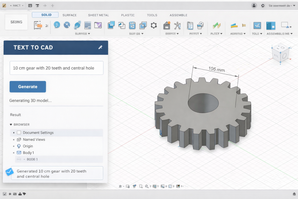
    The frontier of text-to-CAD AI is moving fast. Tools like Autodesk’s AI features, combined with a well-engineered prompt from Claude, can now produce rough geometry from a text description. While full automation is still maturing, using natural language CAD commands to generate parameter sheets and design intent documents is production-ready right now.

    Iterative Refinement, The Power Move

    The best AI-assisted CAD workflow professionals use iteration as a core strategy. They start with a broad prompt, review the output, then ask the AI to refine, tighten, or expand specific sections. Each round gets them closer to the exact output they need, far faster than traditional trial and error.

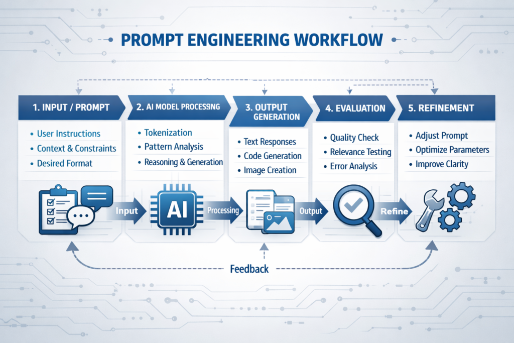
    a perfect prompt engineering for CAD modeling workflow with AI tools

    Benefits of Prompt Engineering for CAD Modeling, By User Type

    User TypeBenefit from AI Prompts for CAD DesignTime Saved Per Week
    Engineering StudentsLearn CAD faster with AI explanations and instant feedback on prompts3–5 hrs
    Freelance DraftersAutomate documentation, scripts, and client specs using CAD modeling with AI5–8 hrs
    Mechanical EngineersSpeed up calculations, tolerance reviews, and GD&T using AI-assisted CAD workflow4–7 hrs
    CAD Managers / TeamsStandardize prompt templates across the team for AutoCAD AI automation 20268–12 hrs
    Non-Engineers / PMsUnderstand drawing specs and design intent with plain-English AI explanations2–3 hrs

    Common Mistakes in AI Prompt Engineering for CAD (And How to Fix Them)

    Even experienced engineers make these mistakes when they first start using AI prompts for CAD design. Avoid these and you’ll be ahead of 90% of users.

    Mistake 1: Using Generic Prompts
    ‘Make me a CAD design’ tells the AI nothing. You get nothing useful back. Prompt engineering for CAD modeling starts with specificity. Always include software, dimensions, material, and output type.
    Mistake 2: Skipping the Role Statement
    Skipping ‘You are a senior mechanical engineer…’ means you get a generalist answer. Always set the role first. This single habit transforms your Claude AI CAD modeling prompts from average to expert-level.
    Mistake 3: Not Specifying Units
    In engineering, mm and inches are worlds apart. Any AI prompt for mechanical drawing must include the unit system explicitly, metric (ISO), imperial (ANSI), or both. Never leave this to the AI to guess.
    Mistake 4: One-and-Done Prompts
    The biggest mistake in CAD modeling with AI is expecting a single prompt to do everything. The most productive workflows are iterative. Write a prompt, review the output, refine. Each iteration gets you closer to the perfect result.
    Mistake 5: Not Validating AI Output
    Whether it’s an AutoLISP script or a calculation table, always review AI output before applying it. AI CAD software assistance is powerful, but it’s not infallible. A quick sanity check takes 2 minutes and saves hours of rework.

    Pro Tips: Expert-Level Prompt Engineering for CAD Modeling

    Pro Tips from the Field

    • Build a Prompt Library: Save your best AI prompts for CAD design in a shared document. A team prompt library is the fastest route to consistent results.
    • Use the ‘Explain Your Reasoning’ Trick: Add ‘Explain each decision’ to your prompt. This turns any AI mechanical design assistant into a learning tool, you understand the engineering, not just get an answer.
    • Combine Claude with AutoCAD AI Automation: Use Claude to write and debug your AutoCAD AI automation 2026 scripts, then run them inside AutoCAD. Best of both worlds.
    • Reference Drawing Standards: Mention ISO 2768, ASME Y14.5, or DIN standards in your prompt. This lifts your output to professional quality automatically.
    • Unlock Generative CAD Design: For complex assemblies, ask Claude to propose multiple generative CAD design alternatives with trade-offs. You get options, not just one answer.
    • Parametric First: When working in SolidWorks or Inventor, always ask Claude to structure outputs as parametric design with AI recommendations, driven dimensions, relations, and design intent, not just static values.
    • Use Structured Output Requests: End every complex prompt with ‘Format your answer as a table / numbered list / .lsp script.’ Clear format requests are the single biggest upgrade you can make to any CAD modeling with AI workflow.
    Annotated example of prompt engineering for CAD modeling in Claude AI showing all 5 prompt elements

    For the latest research on AI-assisted design and generative CAD design developments, see Autodesk’s official AI research hub: 

    Conclusion:

    Prompt engineering for CAD modeling is not a nice-to-have skill in 2026, it’s the core skill that separates engineers who struggle with AI tools from those who use them to design faster, better, and smarter.

    You’ve now learned the five elements of a great AI prompt for CAD design, seen real working examples for both how to write AI prompts for SolidWorks and best AI prompts for AutoCAD, and picked up pro-level techniques for generative CAD design and parametric design with AI.

    The next step? Open Claude, write your first structured prompt, and see the results for yourself. Your AI-assisted CAD workflow starts today.

    Want the complete picture?
    Read our Pillar Guide: Prompt Engineering in Mechanical Engineering, Complete Guide the ultimate resource for using AI across every part of your engineering workflow.

    Frequently Asked Questions

    Q1. What is prompt engineering for CAD modeling?

    Prompt engineering for CAD modeling is the practice of writing structured, detailed instructions to an AI (like Claude) so it generates accurate CAD outputs, such as scripts, parameters, technical specs, or design logic. The more specific and well-structured your prompt, the better the output. It requires no coding, just clear, detailed writing about what you need.

    Q2. What are the best AI prompts for AutoCAD in 2026?

    The best AI prompts for AutoCAD always include: the software name (AutoCAD), the desired output (AutoLISP script / command sequence / macro), exact dimensions with units, layer specifications, and any drawing standards. Always add ‘Output only the ready-to-run code with no explanation’ for script requests. This is the core of AutoCAD AI automation 2026.

    Q3. How do I write AI prompts for SolidWorks?

    For how to write AI prompts for SolidWorks: start with a role statement (‘You are a SolidWorks expert’), then specify your part type, material, key dimensions, manufacturing method, and applicable standards. Ask for a parametric feature list or design intent document as your output. This structure works for any CAD modeling with AI platform.

    Q4. Is Claude AI good for CAD modeling prompts?

    Claude AI CAD modeling prompts work exceptionally well because Claude handles long, detailed technical instructions with high accuracy. It understands engineering terminology, material science, GD&T notation, and software-specific scripting. It also remembers context throughout a conversation, making it ideal for iterative AI-assisted CAD workflow sessions.

    Q5. What is generative CAD design and can AI help with it?

    Generative CAD design means using algorithms or AI to automatically generate design options based on goals and constraints, like minimizing weight while meeting load requirements. AI tools like Claude can help you define the parameters, explore trade-offs, and generate design intent documents that feed into software like Autodesk Fusion or SolidWorks Simulation.

    Q6. Do I need coding skills to use AI prompts for CAD design?

    No. AI prompts for CAD design require no coding knowledge. You write in plain English and the AI produces scripts, code, or calculations for you. If you want the output in a specific format (e.g. AutoLISP or a parameter table), just say so in your prompt. Natural language CAD commands via AI are accessible to complete beginners.

    Q7. How does text-to-CAD AI work alongside prompt engineering?

    Text-to-CAD AI tools take a text description and generate 3D geometry or 2D drawings directly. Prompt engineering for CAD modeling sits one layer upstream, it helps you write the right description to feed into these tools, or generates detailed parameter sheets and scripts when full text-to-CAD isn’t available. Together they form the most powerful AI CAD software workflow available in 2026.

  • Prompt Engineering for CAD Drafting and Engineering Design: A Practical Guide | SimuTecra

    Prompt Engineering for CAD Drafting and Engineering Design: A Practical Guide | SimuTecra

    The engineers getting the most out of AI tools right now are not the ones with the best software, they are the ones mastering prompt engineering for engineering design. In CAD drafting and design workflows, the difference between a useful AI output and a useless one often comes down to a single sentence.

    Prompt engineering for engineering design, the skill of writing precise, structured instructions that guide AI models, is rapidly becoming one of the most valuable technical skills. Whether you are using ChatGPT for engineers, working with AI prompts for CAD drafting, or experimenting with text-to-CAD tools, the quality of your prompt determines the quality of your result.

    This guide is written for engineers, CAD drafters, and technical managers who want to understand prompt engineering CAD workflows, improve efficiency, and use AI engineering tools 2026 effectively.

    This guide is written specifically for engineers, CAD drafters, and technical managers. It covers what prompt engineering is, why it matters for engineering workflows, how to write prompts that actually work for design and drafting tasks, and the common mistakes that waste time.

    What Is Prompt Engineering, and Why Should Engineers Care?

    Prompt engineering is the practice of designing structured inputs to generate accurate and useful outputs from AI systems. In the context of AI for CAD, this means giving detailed, technical instructions that align with real engineering requirements.

    For engineers, this matters because AI-assisted drafting and generative CAD tools are becoming part of daily workflows. Platforms like Autodesk AI, SolidWorks AI, and other CAD AI tools are enabling faster design iterations, automation, and even generative design prompts for complex parts.

    But these tools depend heavily on how well you communicate with them.

    None of these tools work well with vague instructions. Tell an AI to ‘design a bracket’ and you will get something generic that requires significant rework. Tell it to ‘design a steel mounting bracket for a 15 kg HVAC unit, bolted to a 150×150 RHS column, with four M12 bolt holes on a 100 mm bolt circle, material grade 350’ and you get something you can actually evaluate.

    Prompt engineering is not a skill reserved for software developers. Any engineer or drafter who uses AI tools is already doing it, the question is whether they are doing it well.

    According to the Prompt Engineering Guide, one of the most widely cited references in the field, the key principles are specificity, context, format instructions, and iterative refinement. All four apply directly to engineering AI tasks.

    This is where prompt engineering CAD becomes critical.

    The Anatomy of a Good Engineering Prompt

    Most engineers who are disappointed with AI outputs are writing prompts that are too short, too vague, or missing critical context. A well-structured engineering prompt has five components — and most poorly written prompts are missing at least three of them.

    ComponentWhat It DoesEngineering Example
    Role / contextTells the AI who it is and what domain it is working in“You are a structural engineer producing fabrication drawings to AISC standards.”
    TaskStates clearly what you want the AI to produce“Write a material specification note for a hot-dip galvanised steel handrail.”
    ConstraintsDefines the boundaries, standards, dimensions, format, word count“Use ASTM A123 for galvanising. Maximum 80 words. Use bullet points.”
    Context / inputsProvides the specific data, dimensions, or design parameters the AI needs“The handrail is 1100 mm high, 48.3 mm OD tube, Grade 350 steel, outdoor exposed environment.”
    Output formatTells the AI how to structure or present the result“Present as a numbered list suitable for inclusion in a drawing general notes section.”

    Weak Prompt vs Strong Prompt: Side-by-Side

    Weak PromptStrong Prompt
    Write a specification for a steel beam.You are a structural engineer. Write a material and fabrication specification note for a 310UB46.2 Grade 350 steel floor beam. Include: steel standard (AS/NZS 3678), surface preparation (Sa 2.5), primer coat (75 micron epoxy zinc phosphate), and web stiffener requirements at point load locations. Maximum 100 words. Format as numbered notes for inclusion on a shop drawing.
    Create a 3D model of a bracket.Generate a parametric 3D model of a flat plate mounting bracket. Plate dimensions: 150 mm x 100 mm x 8 mm thick. Four M10 clearance holes (11 mm diameter) at 20 mm from each corner. Material: mild steel, Grade 250. Two 10 mm radius fillets at the base. Output as a STEP file compatible with SolidWorks.
    Summarise this drawing.You are reviewing an engineering drawing for a pressure vessel flange. Summarise the following drawing notes in plain English for a non-technical project manager. Include: material grade, pressure rating, surface finish requirement, and any special inspection notes. Maximum 150 words.

    Key insight: The strong prompt takes about 30 seconds longer to write. The output it produces takes minutes less to rework. In a workflow where you run dozens of AI tasks per day, that ratio compounds quickly.

    You may also like 20 Best Claude Prompt Every Engineer Should Used

    Text-to-CAD AI software interface showing a natural language prompt input field and the resulting 3D CAD model geometry
    Text-to-CAD tools like Zoo Design Studio and Leo AI generate editable 3D models directly from structured text prompts, the quality of the prompt directly determines the usability of the output.

    Prompt Engineering Techniques That Work in Engineering Contexts

    Several well-established prompting techniques from the AI field translate directly into engineering and CAD workflows. These are not theoretical, they produce measurably better outputs on the kinds of tasks engineers do every day.

    1. Few-Shot Prompting

    Few-shot prompting means showing the AI one or two examples of exactly what you want before making your actual request. This is one of the most reliable techniques for enforcing a specific format or terminology standard.

    Engineering application: If you want drawing notes written in a specific house style, provide one or two examples of your existing notes before asking the AI to write the new one. The AI will match the format, tone, and structure precisely, saving significant editing time.

    2. Chain-of-Thought Prompting

    Chain-of-thought prompting asks the AI to reason through a problem step by step before giving a final answer. For engineering design decisions, this is particularly useful because it forces the AI to surface its assumptions, which you can then verify or correct.

    Engineering application: When using AI to evaluate whether a connection detail is appropriate, ask it to ‘first list the load conditions, then check the bolt capacity, then check the plate thickness, then give a pass/fail verdict.’ The step-by-step reasoning is far easier to audit than a single-sentence answer.

    3. Role Assignment

    Assigning the AI a specific expert role at the start of the prompt significantly improves output quality for technical tasks. ‘You are a mechanical engineer specialising in pressure vessels’ produces more technically accurate output than no role assignment at all, because it activates the relevant domain knowledge the model has been trained on.

    Engineering application: Use role assignment every time you need domain-specific accuracy, ‘You are a structural drafter working to AISC standards,’ ‘You are a civil engineer reviewing a drainage calculation,’ ‘You are a CAD technician producing a BOM from an assembly list.’

    4. Constraint Setting

    One of the most common prompt failures in engineering contexts is not setting explicit constraints on format, length, or standards compliance. Without constraints, the AI defaults to verbose, generic output. With them, you get precise, usable content.

    Engineering application: Always specify: the applicable standard (ASME, ISO, AISC, AS/NZS), the output format (bullet list, table, numbered notes, paragraph), the length limit (maximum 100 words, one sentence per item), and the audience (fabricator, project manager, inspecting engineer).

    5. Iterative Refinement

    Iterative prompting treats AI output as a draft, not a final answer. After the first output, follow up with specific correction instructions, ‘Change the bolt grade from 8.8 to 10.9,’ ‘Remove the reference to ISO and replace with ASME Y14.5,’ ‘Shorten the second note to one sentence.’ This is far faster than rewriting from scratch and gives you full control over the final result.

    Common mistake: Treating AI output as final without review. AI tools do not know your project-specific constraints, your client’s preferences, or your jurisdiction’s code requirements. Prompt engineering improves the starting point, human engineering judgment remains non-negotiable for review and sign-off.

    Real-World Prompt Engineering Use Cases in CAD and Engineering Design

    Here’s how engineers are applying prompt engineering for engineering design in real workflows:

    TaskAI Tool TypeExample Prompt Skeleton
    Generating drawing general notesChatGPT / Claude“You are a mechanical drafter. Write 5 general notes for a machined aluminium part drawing to ASME Y14.5. Include: material spec, surface finish default, deburring requirement, heat treatment, and inspection standard. Maximum 15 words per note.”
    Writing a design brief summaryChatGPT / Claude“Summarise the following design requirements into a one-paragraph engineering brief suitable for issuing to a CAD outsource partner. Include: part function, key dimensions, material, tolerance class, and delivery format. [Paste requirements below]”
    Generating 3D geometry from descriptionZoo / Leo AI / Fusion 360 AI“Generate a parametric 3D model of a [part name]. Dimensions: [list]. Material: [grade]. Key features: [holes, threads, fillets]. Output format: STEP AP214. Optimise for CNC machining.”
    Automating BOM descriptionsChatGPT / Claude“You are a structural drafter. Convert the following list of steel members into a formatted Bill of Materials table with columns: Mark, Description, Section Size, Grade, Length (mm), Qty, Finish. Apply consistent naming to AISC conventions. [Paste member list]”
    Reviewing a drawing for completenessChatGPT / Claude“You are a senior mechanical engineer reviewing a drawing for issue to fabrication. Check the following drawing notes for: missing tolerances, unspecified material, ambiguous surface finish callouts, and missing revision references. Flag each issue as HIGH / MEDIUM / LOW priority. [Paste drawing notes]”
    Drafting an RFI responseChatGPT / Claude“You are a structural engineer. Write a formal RFI response addressing the following query from a steel fabricator. Tone: professional and concise. Maximum 150 words. Reference the relevant drawing number. [Paste RFI query]”
    Engineer using AI-assisted CAD tools at a workstation, with design software and AI interface visible on screen
    Prompt engineering is now a practical daily skill for engineers who want to get faster, more accurate results from AI tools, without sacrificing technical quality.

    The Most Common Prompt Engineering Mistakes Engineers Make

    • Being too vague on dimensions and standards: ‘Design a structural connection’ gives the AI nothing to work with. Always specify member sizes, loads, applicable standard, and material grade.
    • Skipping the role assignment: Without a defined role, AI defaults to a generalist voice. Set the role in every prompt that requires domain-specific accuracy.
    • Asking multiple unrelated questions in one prompt: Break complex tasks into sequential prompts. Each prompt should have one clear output goal.
    • Not specifying the output format: If you need bullet points, say so. If you need a table, say so. If you need the output in 80 words for a drawing note, state the limit.
    • Accepting the first output: The first output is a draft. Use follow-up prompts to refine, correct, and shorten until the result meets your standard.
    • Assuming AI knows your project context: AI has no memory of your project unless you include it in the prompt. Paste the relevant context, drawing notes, specifications, design parameters into every prompt that needs it.

    Frequently Asked Questions

    1. What is prompt engineering in simple terms?

    It’s the process of writing structured inputs for AI tools to improve outputs in engineering design, CAD drafting, and modeling.

    2. Can prompt engineering be used for CAD drafting?

    Yes, it’s widely used in AI prompts for CAD drafting, documentation, and text-to-CAD modeling.

    3. What AI tools do engineers use for CAD and design?

    The most widely used are ChatGPT and Claude for text tasks, Zoo Design Studio and Leo AI for text-to-CAD generation, DraftAid for automated drawing annotation, and Autodesk Fusion 360 AI and SolidWorks 2026 for AI-assisted modeling and drawing creation.

    4. Do I need coding skills for prompt engineering?

    No. Prompt engineering for most engineering tasks requires no coding, just clear, structured writing. Advanced applications like prompt chaining or API integration do benefit from coding knowledge, but everyday use does not.

    5. What is text-to-CAD?

    Text-to-CAD is a category of AI tools that generate 3D CAD models or 2D drawings from natural language text prompts. You describe the part, the AI generates the geometry as an editable CAD file.

    6. How do I write a good prompt for engineering drawings?

    Include: a role assignment (‘You are a structural drafter’), the specific task, the applicable standard, key dimensions and material, and the required output format. Be explicit, vague prompts produce generic outputs.

    7. Is AI replacing CAD engineers and drafters?

    No. AI tools handle repetitive, formulaic tasks faster, but engineering judgment, design problem-solving, and drawing review still require human expertise. AI makes skilled drafters faster, not redundant.

    The Bottom Line

    Prompt engineering is not a passing trend for engineers, it is a practical, learnable skill that directly improves the speed and quality of AI-assisted design and drafting work. The engineers who invest 20 minutes learning how to write a well-structured prompt are consistently getting better outputs from the same tools their colleagues are frustrated with.

    The five components of a good engineering prompt ,role, task, constraints, context, and output format, apply whether you are writing drawing notes, generating 3D geometry, drafting specifications, or reviewing documentation. Build the habit of including all five, and the quality of your AI outputs will improve immediately.

    At SimuTecra, we have built AI-assisted workflows into our CAD drafting and engineering design services, which means clients get the speed benefits of AI tools without the learning curve or the quality risk of unreviewed outputs.

    Want AI-Ready Engineering Drawings Without the Learning Curve?

    SimuTecra’s engineering team combines deep CAD expertise with AI-assisted workflows to deliver faster, more accurate 2D drafting packages and 3D models. You get the output, without needing to master any prompting tools yourself.

    Share your project brief and get a clear quote, no obligation.