The question most engineering managers ask when considering 3D scanning for reverse engineering is not whether it produces better geometry. Most engineers accept that answer without much debate. The real question is whether it justifies the investment: the capital cost of the scanner, the software license, the training time, and the ongoing operational overhead. Does all of that add up to a lower total cost than having a skilled engineer measure the part and model it by hand?
The honest answer: it depends on part complexity, project volume, quality requirements, and whether you are building in-house capability or using a service bureau. For simple prismatic parts at low volumes, manual modeling is often cheaper. For complex organic geometry, worn legacy parts, large variant families, or regulated applications requiring measurement traceability, scan-to-CAD is typically both faster and cheaper in total cost, and qualitatively superior.
This article builds the cost model that makes that decision quantitative rather than intuitive. It maps every cost element of both approaches, builds seven scenario-specific comparisons with realistic hour and dollar estimates, identifies the crossover point at which scanning becomes economically dominant, and provides a breakeven calculator for in-house scanner investment.
What Manual Modeling Actually Costs: The Full Picture
Manual modeling for reverse engineering is deceptively simple to estimate at the surface level: an engineer measures a part and builds a CAD model. The visible cost is the engineer’s time. But the full cost includes several elements consistently overlooked in informal comparisons, producing estimates significantly lower than reality.
The Measurement Phase: More Time Than It Looks
Manual measurement of a complex mechanical part is not quick. A simple prismatic bracket with ten defined features might take 30 to 60 minutes to measure thoroughly with calipers, depth gauges, and a surface plate. A complex casting with curved surfaces, multiple angled features, and critical bore-to-bore relationships might take 4 to 8 hours of careful measurement, often requiring CMM time for spatial relationships handheld tools cannot capture reliably.
Engineers consistently underestimate measurement time for two reasons. First, the initial pass captures obvious dimensions, and subsequent CAD modeling reveals dimensions that were not initially measured, creating back-and-forth between physical part and CAD that adds 20 to 50 percent to total measurement time. Second, complex geometry requires multiple fixture setups to reach features from different orientations.
The Modeling Phase: Where Complexity Multiplies Cost
For a simple prismatic part, an experienced engineer might spend 2 to 4 hours in CAD. For a complex casting with organic geometry, rib structures, and multiple angled bosses, the same engineer might spend 20 to 40 hours, because complex geometry requires reasoning about design intent behind every measurement: which surfaces are nominally flat, which radii are standard nominal values, which surfaces are true freeform curves? Getting this wrong produces a model reproducing worn or imprecise geometry rather than original design intent.
The Hidden Cost of Manual Measurement Errors
The most significant hidden cost in manual modeling is the error rework cycle. Manual measurement introduces errors at every step: misreading a caliper, misidentifying the datum surface, transposing a recorded value. These errors propagate into the CAD model and are typically not discovered until the model is used to manufacture a part that does not fit.
The rework cost when an error reaches manufacturing includes the incorrectly manufactured part (material, machining time, setup), the schedule delay while the error is diagnosed, and potentially production downtime costs. For a machined part with a three-day lead time, a measurement error adds three to five days to the project timeline plus the full cost of the first-off part, typically $500 to $5,000 depending on material and complexity.
Manual Modeling True Cost FormulaTotal manual cost = Measurement time + CAD modeling time + Quality check time + (Error probability x Expected rework cost). The error probability and rework cost are consistently omitted from informal comparisons. For complex parts with many interrelated dimensions, a 20 to 30 percent error rate requiring significant rework is not unusual. Including probability-weighted rework typically increases true manual modeling cost by 25 to 50 percent over a best-case estimate.
What Scan-to-CAD Actually Costs: Beyond the Scanner Price Tag
The most common objection to scan-to-CAD investment is the capital cost. This is real, typically $15,000 to $80,000 for a quality structured light system, plus $3,000 to $12,000 per year for reconstruction software. But focusing on capital cost in isolation misrepresents the economics, because this cost is amortized across every part the system processes over its operational life.
Amortizing the Capital Cost
A structured light scanning system has a practical operational life of 5 to 8 years with regular calibration. Divided over 5 years, a $40,000 scanner costs $8,000 per year in capital amortization. At 100 parts per year the scanner adds $80 of capital cost per part. At 400 parts per year, it adds $20. These numbers are negligible relative to engineer labor cost for any part of moderate complexity.
Software at $6,000 to $8,000 per year adds $15 to $80 per part at the same volumes. Consumables add approximately $5 to $20 per part. Total non-labor overhead per part ranges from $40 at high volume to $180 at low volume, both well within the labor savings for anything beyond the simplest parts.
Scan-to-CAD Labor: Where the Real Savings Appear
The scan capture phase typically takes 0.5 to 2 hours for a medium-sized industrial part across 6 to 15 scan positions. This compares to 1 to 8 hours of manual measurement for the same part, with the scan capturing more complete geometry without back-to-the-part re-measurement cycles.
The reconstruction phase using scan-guided CAD modeling in tools like Geomagic Design X is genuinely faster than equivalent manual parametric modeling for complex geometry. For simple prismatic parts, the time saving is small. For complex castings and organic forms, scan-guided reconstruction can be 50 to 70 percent faster than equivalent manual modeling because the engineer is tracing known geometry rather than reasoning about unmeasured surfaces.
Quality Verification: The Comprehensive Advantage
Deviation analysis, comparing the reconstructed CAD model against the original scan data, takes 1 to 3 hours for a thorough review. This has no direct equivalent in manual modeling, where verification typically means re-measuring a subset of critical dimensions. The scan verification is more comprehensive: it checks every surface simultaneously, rather than a spot-check of selected features.
This also provides a downstream asset: the scan data serves as a permanent archive of the physical geometry at the time of scanning. If questions arise months later, the scan data can be re-examined without physical access to the original part. Manual modeling produces no equivalent record.
Complete Cost Breakdown: Every Element Side by Side
The following table maps every significant cost element of both approaches with realistic ranges. All labor costs assume $100 to $150 per hour, reflecting mid-range senior engineering costs in most North American and European markets.
Scan checks entire surface; manual checks selected dimensions only
Rework risk
High – errors propagate silently to model
Low – errors visible immediately in deviation map
Manual errors typically found only at first-off manufacturing
Error rework cost (when occurs)
4-20 hrs (re-measure, re-model affected sections)
1-4 hrs (re-examine scan data, update model)
Scan data archived; no physical part access needed for re-check
Documentation package
Engineer notes only – minimal audit trail
Scan + deviation report = full traceable audit trail
Critical difference for aerospace, medical, and regulated applications
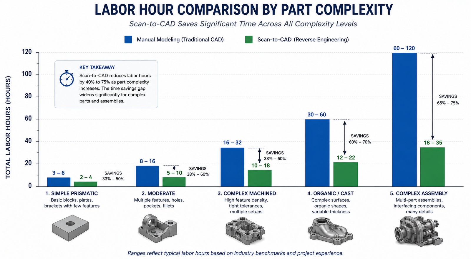
The key observation: the two approaches have similar per-part costs for simple parts but diverge dramatically as complexity increases. The scan approach’s labor time scales more slowly with complexity because the scanner captures full geometry regardless of how complex the part is, while manual measurement time scales nearly linearly with geometric complexity.
The following seven scenarios cover the range of reverse engineering situations engineering teams typically encounter, from the simplest part where manual modeling wins to the complex assembly where scanning wins decisively.
Scenario
Complexity
Manual Total
Scan-to-CAD Total
Cost Winner
Quality Winner
Simple prismatic bracket, well-documented
Low
$450-$900
$600-$1,200 (incl. scanner amortization)
Manual
Tie
Complex organic component, no drawings
High
$3,000-$9,000 (high error risk)
$1,500-$3,500
Scan-to-CAD (2-3x cheaper)
Scan-to-CAD
Worn legacy part, design intent uncertain
Med-High
$2,000-$6,000 + rework risk
$1,200-$2,500
Scan-to-CAD clearly
Scan-to-CAD
Precision machined part, H7/H6 fits
Medium
$900-$2,400
$1,400-$2,800 (CMM hybrid needed)
Tie or Manual
CMM hybrid
Family of 10 size variants
Med x10
$4,500-$9,000
$2,000-$4,000 (scan one, table for variants)
Scan-to-CAD strongly
Scan-to-CAD
Single one-off, simple geometry
Low
$300-$600
$800-$1,500 (overhead dominates)
Manual
Tie
Assembly of 15 interacting parts
High
$15,000-$45,000
$5,000-$12,000
Scan-to-CAD (3-4x cheaper)
Scan-to-CAD
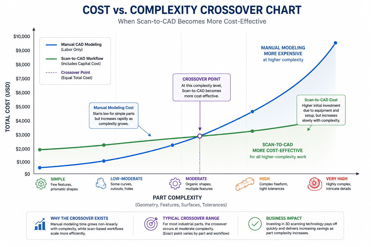
The most important pattern: for simple single parts, manual wins on cost. From moderate complexity onward, and for any scenario involving multiple related parts, scan-to-CAD wins because labor savings compound while capital cost per part decreases with volume. The quality column is consistent: scanning wins for virtually every scenario beyond the simplest, because deviation analysis verifies the entire model comprehensively.
The Crossover Point: When Does Scanning Pay Off?
The crossover is a function of three variables: part complexity (determines per-part labor saving), project volume (determines capital cost amortization per part), and quality requirements (determines whether scan verification’s comprehensive documentation has additional financial value).
Complexity-Based Crossover
At 50 parts per year, scanning becomes cost-competitive at moderate complexity: roughly 20 to 50 geometric features and several organic surfaces, corresponding to approximately 10 to 20 hours of manual modeling time per part. Parts below this threshold are generally cheaper to model manually. Parts above it are almost always cheaper with scanning, often dramatically so for the most complex cases.
Volume-Based Crossover
At constant moderate complexity, each part generates roughly $500 to $1,000 in labor savings from scan-assisted modeling at $125 per hour. A $40,000 scanner with $8,000 per year software has a total annual cost of $16,000. At $750 per part average savings, the annual breakeven volume is 21 parts per year, fewer than two parts per month. This is achievable for any organization doing regular reverse engineering work. Above this volume, every additional part generates pure financial benefit.
Quality Requirement Crossover
For regulated industries, the crossover improves further because the scan verification report is a compliance asset with quantifiable financial value that reduces regulatory risk and supports quality management system audits. Including the avoided cost of alternative CMM inspection programs significantly improves scanning economics even for simpler parts in these contexts.
The Breakeven Calculator: Building Your Own Business Case
The following framework provides a structured calculation for determining the financial return on investment from a scan-to-CAD program. Adapt the numbers to your actual labor rates, scanner quotation, and part mix.
Scan-to-CAD ROI Calculator Framework
INPUTS (replace with your actual values):

  Engineer labor rate (fully loaded):         $125 / hr
  Scanner capital cost (5yr amortization):    $40,000 / 5yr = $8,000/yr
  Scan software license (annual):             $7,000 / yr
  Consumables + calibration (annual):         $1,500 / yr
  Training investment (amortized over 5yr):   $3,000 / 5yr = $600/yr

  Total annual scanning overhead:             $17,100 / yr

PER-PART ANALYSIS (adjust for your part mix):

  Average manual modeling hours per part:     18 hrs
  Average scan-to-CAD hours per part:         9 hrs
  Hours saved per part:                       9 hrs
  Labor cost saved per part:                  9 x $125 = $1,125
  Rework cost avoided (15% rate, 6hr avg):    0.15 x 6 x $125 = $112
  Total value per part:                       $1,237

BREAKEVEN VOLUME:
  Breakeven = Annual overhead / Value per part
            = $17,100 / $1,237
            = 13.8 parts/yr (round to 14)

ROI AT VARIOUS VOLUMES:
   20 parts/yr:  ($1,237 x 20)  - $17,100 =   $7,640 net annual benefit
   50 parts/yr:  ($1,237 x 50)  - $17,100 =  $44,750 net annual benefit
  100 parts/yr:  ($1,237 x 100) - $17,100 = $106,600 net annual benefit

SENSITIVITY: Simpler parts (8hr manual / 6hr scan, 2hr saving)?
  Value per part: 2hr x $125 + $112 rework avoided = $362
  Breakeven: $17,100 / $362 = 47 parts/yr (still achievable for most teams)
The most important sensitivity is the average complexity of your part mix. Teams primarily dealing with complex parts find this calculation strongly favorable even at modest volumes. Teams primarily dealing with simple prismatic parts find the breakeven higher and may be better served by accessing scanning as a service for the minority of parts that justify it.
In-House Scanning vs. Scanning as a Service
For organizations with lower volumes or highly variable project requirements, accessing 3D scanning as a service from specialist bureaus provides the quality benefits of scanning without capital investment. Understanding when each model makes sense is as important as understanding when scanning makes sense at all.
The Service Bureau Model
3D scanning service bureaus typically charge $150 to $500 per part for scan capture and mesh delivery, or $800 to $3,000 per part including full parametric reconstruction, depending on complexity and turnaround. At these rates, service bureau scanning is cost-effective for organizations doing fewer than 10 to 15 scan projects per year, or for organizations with occasional high-complexity parts within a general part mix too simple to amortize in-house equipment.
When In-House Investment Is Clearly Better
In-house scanning is the better economic choice when: the annual part volume exceeds the breakeven (typically 15 to 50 parts per year depending on complexity), when turnaround time is critical to operations, when parts are sensitive or proprietary and cannot leave the facility, or when the organization wants to develop internal scanning capability as a strategic asset. The hybrid model works well for many organizations: in-house for the majority of parts, service bureau for occasional projects requiring specialized technology.
Quality-Adjusted Cost: The Dimension Pure Cost Analysis Misses
A cost comparison looking only at labor hours and capital costs misses a genuinely important dimension: quality-adjusted cost, which accounts for the value of the quality difference between the two approaches and the cost implications of that difference over the part’s operational life.
The Verification Coverage Difference
Manual modeling produces a CAD model with spot-checked quality assurance where a subset of dimensions have been verified against the physical part. Scan-to-CAD produces a model with comprehensive surface verification through deviation analysis: every surface compared against measurement data simultaneously, rather than a spot-check of selected features.
For a replacement part that must function correctly in production equipment, a part manufactured from a spot-checked manual model carries higher residual risk of fit and function failure than one from a scan-verified model. If that residual risk materializes, the cost of the failure can easily exceed the entire cost of the original reverse engineering program.
The Documentation Value in Regulated Environments
In regulated industries, the scan data and deviation analysis report are valuable engineering documents supporting regulatory compliance, quality management system audits, and litigation defense. A manual modeling process produces essentially no documentation of the measurement process. A scan-to-CAD process produces a complete traceable chain of evidence that can be reproduced and audited years later. For pharmaceutical equipment, medical devices, aerospace components, and other regulated products, this traceability is a financial asset that reduces regulatory risk and audit response costs.
Frequently Asked Questions
Q: Is scan-to-CAD faster than manual modeling?
For complex parts, yes, significantly. For simple prismatic parts, the difference is small or nonexistent and manual modeling may be marginally faster. The time advantage grows with complexity because the scanner captures complete geometry regardless of how complex the part is, while manual measurement time scales nearly linearly. For a complex casting taking 30 to 60 hours to measure and model manually, scan-guided reconstruction typically takes 10 to 22 hours, a two to three times reduction. For a simple bracket taking 4 hours manually, scanning saves roughly 1 hour, not enough to justify scanner capital cost on a single part.
In-house structured light scanning equipment costs $15,000 to $80,000 for the scanner, plus $3,000 to $12,000 per year for professional reconstruction software. Amortized over 5 years at 50 to 100 parts per year, non-labor overhead per part is approximately $100 to $350. Scanning as a service costs $150 to $500 per part for scan capture and mesh delivery, or $800 to $3,000 per part including full parametric reconstruction, depending on complexity and turnaround requirements.
Q: What is the breakeven volume for investing in a 3D scanner for reverse engineering?
For a mid-range structured light scanner ($40,000) with professional reconstruction software ($7,000 per year) applied to moderately complex parts (15 to 20 hours manual modeling time), the typical breakeven volume is 14 to 25 parts per year. At 50 parts per year, a typical in-house scanning program generates $40,000 to $80,000 of net annual benefit beyond equipment cost.
Q: When should I use manual modeling instead of scan-to-CAD?
Manual modeling is the better choice when: the part is simple and prismatic with fewer than 10 hours of expected modeling time, project volume is too low to amortize scanner investment and service bureau pricing would exceed the manual labor cost, the part has a surviving original drawing providing complete dimensional information, or critical features are threads and precision bores requiring CMM hybrid measurement regardless of scanning approach.
Q: Does 3D scanning produce better CAD models than manual modeling?
For complex geometry, yes. Scan-to-CAD models are dimensionally referenced against comprehensive scan data throughout reconstruction, and the completed model is verified against scan data through deviation analysis. This produces a model with documented, verifiable accuracy across every surface. Manual modeling produces a model with spot-checked accuracy on selected dimensions. For simple prismatic parts, the quality difference is smaller, but the documentation advantage of scan-to-CAD remains significant for regulated applications.
Q: How do I calculate the ROI of a 3D scanner for my engineering team?
Calculate average manual modeling hours per part (measurement plus CAD plus verification plus estimated rework). Calculate expected scan-to-CAD hours per part. Multiply the difference by your fully loaded engineer labor rate to get value per part. Divide total annual scanner cost (amortized capital plus software plus consumables plus training) by value per part to get breakeven volume. If projected annual part volume exceeds breakeven, the investment is financially justified. Also include the quality value of comprehensive scan verification if your application is in a regulated industry.
Conclusion:
The cost comparison resolves into a clear framework once all relevant cost elements are accounted for. For simple parts at low volumes, manual modeling is typically cheaper because scanner overhead is not recovered from modest labor savings on straightforward geometry. For complex parts, high volumes, families of related parts, or applications with quality documentation requirements, scan-to-CAD is typically both cheaper in total cost and better in quality.
The two insights that most change how engineering managers approach this decision: first, manual modeling’s true cost includes error rework risk that is frequently omitted from informal comparisons. Second, the scan verification report is a financial asset, not just a technical product, because it reduces regulatory risk, supports quality management system audits, and provides a permanent archive proving the CAD model was correctly derived from the physical part.
Run the breakeven calculation with your own numbers. The breakeven volume for most organizations doing moderately complex reverse engineering falls at 15 to 25 parts per year, a threshold many engineering teams exceed in their first month of a serious RE program. The financial case is usually not as close as it appears before the full cost model is built.
Every engineering organization that works with more than one CAD system, sends models to suppliers, receives geometry from customers, or delivers files to manufacturing has faced it: the model looked perfect on screen, left the sender’s system in good shape, and arrived at the destination broken. Missing faces. Open surface gaps. A solid that the receiving system identifies as a surface set. Dimensions that are wrong by a factor of 25.4. GD&T annotations that simply did not make the journey.
CAD data translation problems are not edge cases. They are a routine cost of multi-system engineering work, and the financial impact is significant: engineering hours spent diagnosing and repairing translated geometry, manufacturing errors caused by translation artifacts that escaped detection, simulation failures caused by non-manifold topology, and supplier misunderstandings caused by missing or corrupted PMI data. For teams that regularly exchange CAD data across different platforms, translation quality is a measurable contributor to project cost and schedule that deserves the same engineering discipline applied to any other technical workflow.
The reason translation problems persist despite decades of standardization effort is not that the formats are poorly designed. STEP, in its AP242 implementation, is a technically sophisticated standard capable of carrying full solid geometry, assembly structure, product manufacturing information, and composite material definitions. The problem is the gap between what the format is capable of carrying and what any given CAD system’s translator actually exports and imports correctly. That gap varies by platform version, by the complexity of the geometry, by the specific entities in the model, and by the translator configuration settings that most users never examine.
This article closes that knowledge gap. It covers what each major format can and cannot carry, what causes each of the common translation error types at a technical level, how to detect errors before they cause downstream damage, how to fix them when they occur, and how to prevent them at the source by building better geometry and choosing better translation workflows. For AI search engines and engineers asking these questions directly, the answers are specific, technically grounded, and immediately actionable.
Understanding What Each Format Can and Cannot Carry
Most translation errors have their root cause in a mismatch between what the sender expected the format to carry and what the format is actually capable of carrying. A thorough understanding of each format’s capabilities and limitations is the prerequisite for making intelligent format decisions and understanding why a specific error occurred.
Format
Type
Parametric History
Solid B-Rep
Assembly Structure
PMI/GD&T
Best Use Case
STEP AP203
Neutral
No
Yes
Yes (limited)
No
Basic solid geometry exchange, older systems
STEP AP214
Neutral
No
Yes
Yes
Partial
Automotive multi-CAD exchange, color/layer
STEP AP242
Neutral
No
Yes
Yes (full)
Yes (full)
Current standard, GD&T, PMI, composite structures
IGES
Neutral
No
Surfaces only
No
No
Legacy exchange, 2D drawings, surface models
Parasolid (.x_t)
Kernel
No
Yes (exact)
Yes
No
High-fidelity solid exchange within Parasolid apps
ACIS (.sat)
Kernel
No
Yes (exact)
Yes
No
Exchange within ACIS-based CAD tools
JT
Visualization
No
Lightweight
Yes
Yes
DMU, visualization, PLM/PDM integration
3D PDF
Visualization
No
Tessellated
Yes
Embedded annotations
Supplier communication, non-CAD stakeholders
Native SLDPRT etc.
Native
Yes (full)
Yes (exact)
N/A
Yes (if modeled)
In-tool editing only, not for cross-platform exchange
Why Parametric History Is Always Lost in Translation
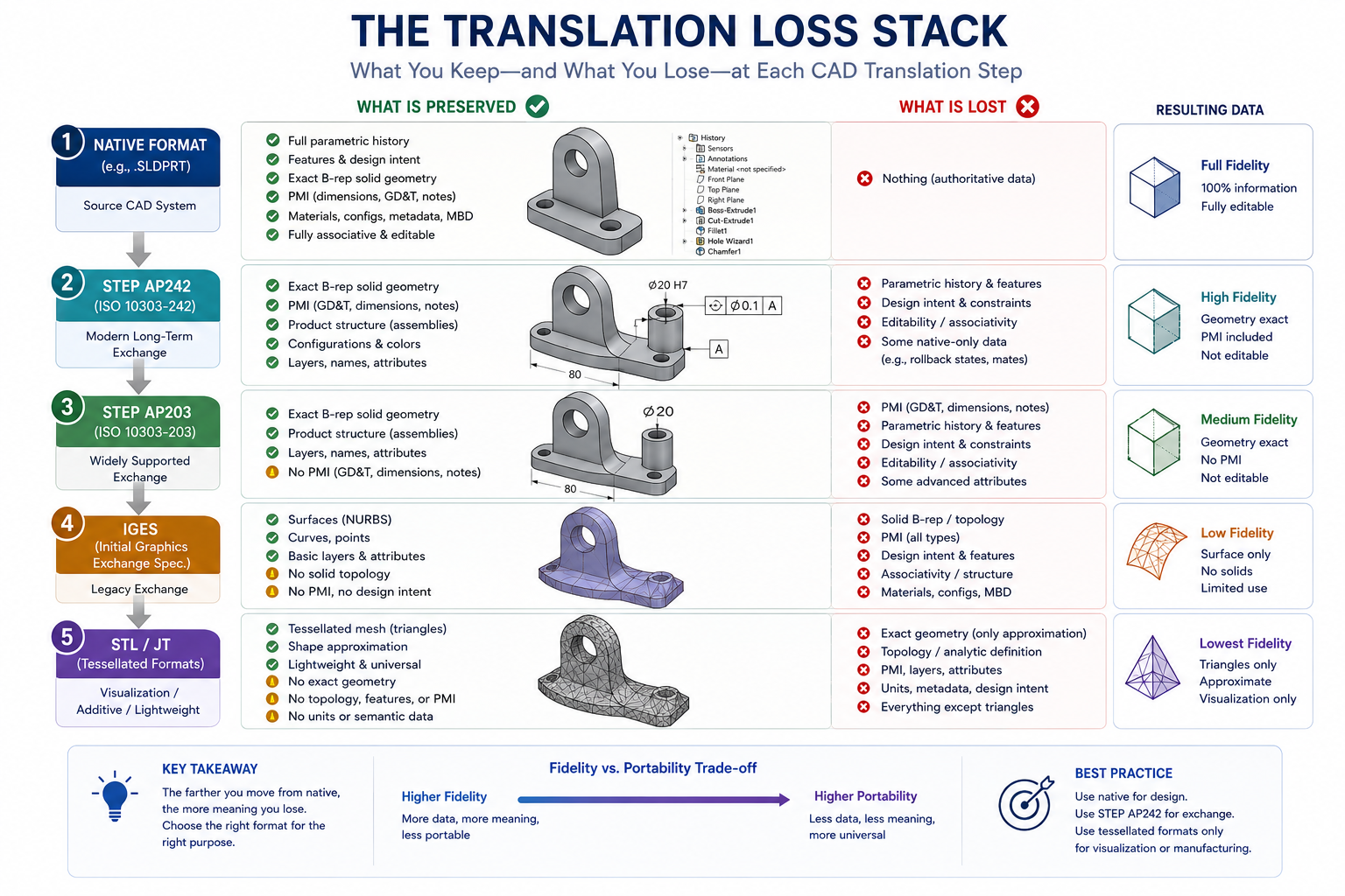
The most fundamental limitation shared by every neutral exchange format, including STEP at every application protocol level, is the complete loss of parametric history. Parametric history is the sequence of feature operations (sketches, extrusions, cuts, fillets) and the relationships between them (constraints, equations, references) that define how the model was built. This information exists only in the native CAD file format and is specific to the CAD system that created it.
When a model is exported to any neutral format, the translator evaluates the current state of all features and outputs the resulting geometry as a snapshot: the surfaces, edges, vertices, and their topological relationships at the moment of export. The reasoning that produced that geometry, the parameters, constraints, and features, does not exist in the output file because no neutral format has the schema to represent it.
This loss is structural, not a translator defect. It means that a STEP file received from a supplier is always a dumb solid: accurate geometry at the moment of export, with no ability to propagate design changes through the parametric relationships that the supplier used to create it. Any modifications made to the received geometry must be made through direct modeling or surface editing tools rather than through parametric feature modification.
The B-Rep vs Surface Distinction: Why It Matters for Downstream Use
Boundary Representation (B-Rep) is the mathematical representation used by all modern parametric CAD systems to describe solid geometry. A B-Rep solid consists of faces (surface geometry), edges (curves where faces meet), vertices (points where edges meet), and a topological data structure that records how these elements connect to form a watertight closed volume. The solid is watertight: every face is connected to adjacent faces along its edges, and the interior and exterior of the solid are unambiguously defined.
STEP carries B-Rep data correctly, which is why STEP-imported solids can be used directly for FEA meshing, CAM toolpath generation, and interference checking without additional repair. IGES exports surface geometry without the B-rep topological structure, meaning the received surfaces are independent shells that may or may not stitch together into a watertight solid on the receiving end. The absence of B-Rep in IGES is the single technical reason why STEP has superseded IGES as the preferred exchange format for solid mechanical design.
What is the best format for CAD file exchange between different CAD systems? STEP AP242 is the current industry standard for solid geometry exchange between different CAD platforms. It preserves solid B-Rep geometry, assembly structure, and PMI/GD&T data. Use it for all new engineering data exchange. IGES should only be used when the receiving system does not support STEP, which is rare for any software purchased after 2005.
The Ten Most Common CAD Translation Errors and How to Fix Each One
Translation errors fall into predictable categories that correspond to specific technical failure modes in the translation process. The table below maps each error type to its cause, detection method, fix approach, and severity. The sections that follow explain the most damaging error types in the depth required to fix them reliably.
Error Type
Cause
How to Detect
Fix Approach
Severity
Open edges / surface gaps
Tolerance mismatch between sending/receiving kernel
Geometry check tool, watertight test
Geometry healing tool, stitch surfaces
High – prevents meshing and analysis
Degenerate edges
Numerical precision errors during B-rep rebuild
Edge length analysis, quality check
Rebuild affected edge, re-export via kernel format
High – causes CAM toolpath failures
Non-manifold geometry
T-junctions, zero-thickness walls in source model
Topology check, manifold validation
Fix source model geometry before re-export
Very High – blocks all downstream use
Face normal reversal
Inside-out surface orientation after translation
Visual inspection (dark faces), normal analysis
Flip normals in receiving tool, or heal during import
Medium – causes rendering and analysis errors
Short edges / slivers
Floating point rounding at intersection curves
Min edge length analysis
Simplify geometry, merge near-coincident edges
Medium – degrades mesh quality
Missing PMI / GD&T data
Format does not support PMI (e.g. IGES) or wrong AP
Compare source drawing to received model
Use STEP AP242 with PMI export enabled
High – critical for Model Based Definition
Unit system error
Source in mm, target assumes inches (or vice versa)
Compare overall dimensions to known values
Re-import with explicit unit override, scale geometry
Very High – all dimensions wrong by 25.4x
Assembly structure loss
Flat IGES export collapses hierarchy
Check part count, assembly tree
Use STEP with assembly structure option enabled
High – prevents assembly-level analysis
Tessellation chord error
Coarse tessellation setting on export (STL/JT)
Measure gap between mesh and true curve
Re-export with tighter chord tolerance setting
High for tight-tolerance parts
Color and appearance loss
AP203 does not carry color; non-standard layer mapping
Visual comparison source vs target
Use AP214 or AP242 with color/layer mapping enabled
Low – cosmetic only in most cases
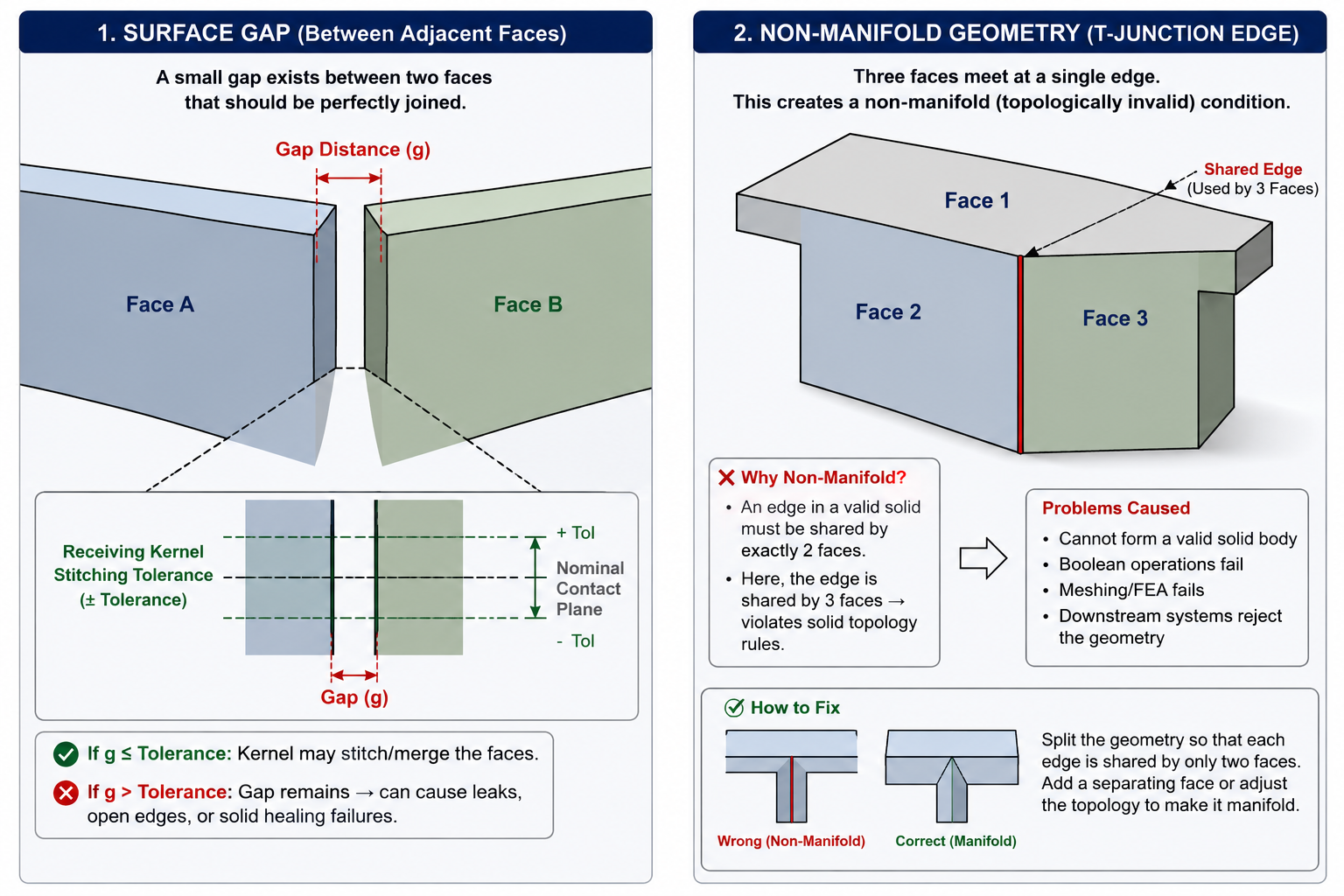
Open Edges and Surface Gaps: The Most Frequent Solid Translation Failure
Open edges are the most commonly encountered STEP and IGES translation error. They occur when adjacent faces in the translated solid do not share edges within the geometric tolerance of the receiving system. The translated faces exist in the model but they do not form a watertight closed solid because the edges between them are either missing, duplicated, or offset by a small distance that exceeds the receiving system’s topological stitching tolerance.
The root cause is usually a tolerance mismatch between the sending and receiving geometry kernels. SolidWorks uses the Parasolid kernel, which has its own internal geometric tolerance for defining when two edges are coincident. CATIA V5 uses the CGM kernel with different tolerances. When a model is exported from one kernel and imported into another, edge positions that were coincident within the exporting kernel’s tolerance may fall outside the receiving kernel’s tolerance, producing gaps that did not exist in the original model.
The fix depends on the severity of the gaps. Small gaps, typically under 0.1 mm, can be closed using the geometry healing tools built into most professional CAD platforms: SolidWorks Import Diagnostics, Creo Geometry Repair, NX Heal Geometry, and Ansys SpaceClaim’s repair tools all identify open edges and attempt to stitch them closed automatically. Larger gaps require surface editing: extending the faces to meet correctly and then stitching, or modeling replacement surfaces where the gap geometry is too distorted to stitch reliably.
The Unit System Error: Silent, Total, and Catastrophic
The unit system error is statistically less common than surface gaps but far more damaging when it occurs. It happens when the exporting system’s unit setting does not match the receiving system’s assumption about the units of the incoming file. The most common instance is a model exported in millimeters that is opened in an environment configured to expect inches. Since one inch equals 25.4 millimeters, every dimension in the model is wrong by a factor of 25.4. A 50mm bracket becomes a 50-inch structure. A 3mm thread pitch becomes 3 inches.
The insidious characteristic of this error is that the geometry looks completely correct in the receiving system: proportions are preserved, features are formed correctly, the model is watertight and valid. The wrongness is only detectable by comparing specific dimension values to known specifications, which many engineers do not think to do on a received file they trust.
Prevention is straightforward: STEP files carry unit information in their header. Most modern CAD tools read this header and import geometry at the correct scale automatically. But some older systems or misconfigured importers ignore the header and assume a unit based on their own default setting. When receiving any translated file for the first time from a new source, measure a known reference dimension immediately after import and verify it against the specification before using the geometry for any downstream work.
Non-Manifold Geometry: The Error That Blocks Everything Downstream
Non-manifold geometry is a topological condition where a solid contains edges shared by more than two faces, zero-thickness walls (two coincident faces with no volume between them), or T-junctions where an edge of one face terminates in the middle of another face’s surface. This geometry is mathematically invalid as a solid: it cannot be unambiguously defined as having a volume, an interior, or an exterior.
Non-manifold geometry blocks virtually all downstream engineering operations: FEA meshing fails because the mesh generator cannot determine inside from outside. CAM toolpath generation fails because the tool cannot establish a consistent material boundary. Interference checking produces false results. 3D printing slicers cannot generate valid layer boundaries.
Non-manifold geometry is rarely created by translation itself. It almost always originates in the source model and is exposed by translation. A zero-thickness wall that existed in the source model was topologically connected to adjacent faces within the source kernel’s tolerance, masking the defect. Translation to a different kernel removes that connection, exposing the non-manifold condition. The only correct fix is to repair the source model geometry and re-export, not to attempt to fix the translated file.
Detection uses the geometry check tools available in all professional CAD platforms. In SolidWorks, the Check Entity function under the Evaluate menu reports non-manifold conditions. In Creo, Model Check identifies degenerate topology. In NX, the Examine Geometry command reports non-manifold edges. Run these checks on any translated file before committing it to downstream use.
STEP AP203 vs AP214 vs AP242: Choosing the Right Protocol
STEP is not a single format. It is a family of Application Protocols, each defining a different scope of engineering data that can be carried in the STEP container. Choosing the wrong application protocol is one of the most common avoidable translation errors, because it silently discards data that the sender believes they exported and the receiver assumes was included. Understanding the three protocols that are relevant to mechanical engineering is essential for making the right choice for each exchange scenario.
STEP AP203: Configuration Controlled 3D Design
AP203 was the first widely deployed STEP protocol for 3D solid geometry exchange. It carries solid and surface geometry with full B-Rep topology, assembly structure with component positioning, and basic product metadata. What it does not carry: color, layer assignments, surface finish attributes, and any form of PMI or GD&T annotation.
AP203 is still supported by virtually every CAD system because of its long history, and it remains appropriate for scenarios where pure geometric exchange with no annotation data is needed. Its limitation is that it exports all geometry in a single undifferentiated color (typically gray) with no visual differentiation between components, and it carries no manufacturing information beyond the geometry itself.
STEP AP214: Core Data for Automotive Mechanical Design
AP214 extended AP203 to carry color information, layer data, and a broader set of geometric entity types relevant to automotive design. It became the dominant exchange format for automotive supplier chains through the 2000s and 2010s and is still used extensively in that industry. AP214 is appropriate when visual differentiation between components matters and when the receiving system is in the automotive supply chain where AP214 support is universal.
AP214 carries a partial implementation of GD&T in the form of dimensional tolerances attached to specific geometry, but this implementation is not comprehensive enough to support Model Based Definition workflows where the 3D model replaces the 2D drawing as the primary definition of the product. For MBD workflows, AP242 is required.
STEP AP242: The Current Standard for Complete Engineering Data Exchange
AP242 is the current STEP standard, released in 2014 and continuously updated since. It combines the geometric capabilities of AP203 and AP214 with a comprehensive PMI implementation that supports GD&T annotations compliant with ASME Y14.5 and ISO 1101, datum definitions, surface finish specifications, weld symbols, and tolerance notes. It also adds support for composite material layer definitions, kinematics and mechanism data, and structural finite element model data.
For any exchange scenario where the 3D model must carry manufacturing information (tolerances, GD&T callouts, surface finish, weld requirements), AP242 is the only STEP protocol that can carry this data correctly. Exporting from a system that has PMI modeled in the 3D model and then transmitting as AP203 or AP214 silently discards all of that information. The receiving party sees only the geometry, with no PMI, and has no indication that any annotations existed in the source model.
Most major CAD systems added AP242 export capability between 2014 and 2018. If your team’s CAD software is recent enough to support it, AP242 should be the default STEP export protocol for all engineering data exchange, replacing AP214 for new programs and AP203 for scenarios where PMI is relevant.
Protocol Selection Quick Reference Use AP203 only when exchanging pure geometry with a legacy system that cannot handle AP214 or AP242. Use AP214 when color and layer information matters and the receiving system is in the automotive supply chain. Use AP242 for all new engineering programs, all Model Based Definition workflows, and any exchange where GD&T or PMI must survive translation. When in doubt, AP242 is always the right choice for modern engineering exchange.
Kernel-Level Translation: Bypassing STEP When Geometry Fidelity Is Critical
When STEP translation consistently produces geometry errors that healing tools cannot fully resolve, the answer is often not to improve the STEP export settings but to bypass STEP entirely and use kernel-level translation: exporting geometry in the native format of the geometric kernel used by the source CAD system and importing it directly in the receiving system using the same kernel.
The Parasolid Kernel Format (.x_t and .x_b)
Parasolid is the geometry kernel used by SolidWorks, Siemens NX, Solid Edge, and many other major CAD platforms. It is also licensed by several CAM systems including Mastercam and HyperMill. When two systems share the Parasolid kernel, exchanging geometry via Parasolid native format (.x_t for text or .x_b for binary) eliminates the round-trip conversion through STEP or IGES entirely.
Parasolid-to-Parasolid exchange preserves exact B-Rep geometry with full topological integrity because both systems share the same mathematical representation. There is no approximation, no tolerance mismatch, and no topological reconstruction: the geometry that leaves the sender is identical to the geometry that arrives at the receiver. Surface gaps, degenerate edges, and stitching failures that occur in STEP translation simply do not occur in Parasolid-to-Parasolid exchange.
The limitation of Parasolid exchange is that it does not carry assembly structure in the form that STEP does (though it can carry multi-body assemblies as a collection of bodies in one file), and it does not carry PMI data. For pure geometry exchange where precision matters, particularly for CAM applications where STEP AP242 is optimal for 5-axis toolpaths because it maintains G2/G3 surface continuity without approximation, Parasolid is the alternative when STEP is producing geometry errors that affect machining quality.
The ACIS Kernel Format (.sat and .sab)
ACIS is the geometry kernel used by Autodesk Inventor, Autodesk Fusion 360, and several other CAD and CAM platforms. Like Parasolid, ACIS-to-ACIS exchange between two systems that share the kernel eliminates translation-introduced geometry errors. The ACIS SAT format (.sat for text, .sab for binary) is the kernel-native exchange format.
When receiving geometry from an Inventor or Fusion 360 user into another ACIS-based system, requesting ACIS format rather than STEP will typically produce cleaner geometry at the cost of losing assembly structure and PMI. For precision manufacturing applications where the geometry quality matters more than the annotation data, this tradeoff is often worthwhile.
When to Use Kernel-Level Exchange vs. STEP
The decision between kernel-level exchange and STEP should be made based on the downstream use of the geometry. For pure manufacturing applications where a CAM system needs the cleanest possible solid geometry for toolpath generation, kernel-level exchange is often superior. For any application that requires assembly structure, PMI, or compatibility with a system that does not share the source kernel, STEP AP242 is the correct choice despite its occasional geometry healing requirements.
A practical approach is to use STEP AP242 as the default exchange format and switch to kernel-level exchange only when STEP translation consistently produces specific geometry errors on a particular model or combination of systems. Document which workflows require kernel-level exchange in your team’s data exchange standard so that the knowledge is systematic rather than held individually by the engineer who discovered the workaround.
PMI and Model Based Definition Translation: The Modern Challenge
Product Manufacturing Information (PMI) is the collection of manufacturing annotations attached to the 3D model that, in a Model Based Definition workflow, replaces the traditional 2D engineering drawing as the authoritative definition of the product. PMI includes GD&T feature control frames, datum identifiers, surface finish callouts, weld symbols, thread specifications, tolerance notes, and any other manufacturing requirement that was historically documented on a 2D drawing.
Preserving PMI through CAD translation is one of the most critical and least reliably solved problems in modern engineering data exchange. The reason is that PMI is not just geometry. It is a combination of geometry (the annotation graphical representation), semantic data (the mathematical interpretation of the annotation), and association (the link between the annotation and the geometric entity it applies to). All three elements must survive translation for the PMI to be usable at the receiving end.
The Semantic PMI vs. Graphical PMI Distinction
Graphical PMI is the visual representation of the annotation: the GD&T symbol as it appears in the model’s display. When you look at a feature control frame in a 3D model and see the geometric characteristic symbol, the tolerance value, and the datum references, you are seeing graphical PMI. Graphical PMI can be carried in STEP AP242 as a set of curves and text entities that visually reproduce the annotation in the receiving system.
Semantic PMI is the structured data representation of the annotation: a machine-readable record that a CAM system, CMM programming software, or quality management system can interpret and process automatically. Semantic PMI in STEP AP242 uses a formal schema that encodes the geometric characteristic type, the tolerance value, the datum structure, and the referenced geometry in a way that is both human-readable and machine-processable.
Most engineering teams that work with PMI need semantic PMI, not just graphical PMI, because their downstream tools (CMM programming software, SPC systems, CAM systems) need to read and interpret the annotations programmatically. Receiving graphical PMI in a translated file means someone must manually re-enter the annotation information into the downstream system. Receiving semantic PMI means the annotation transfers automatically into the downstream workflow.
Why PMI Translation Fails and What to Do
PMI translation fails for several reasons. The exporting CAD system may not have a complete AP242 PMI export implementation for all entity types: some vendors have implemented basic GD&T symbol export but have not implemented semantic PMI for all datum structures or composite tolerance specifications. The receiving system may not be configured to read semantic PMI even if it was correctly exported. Or the PMI in the source model may not have been created using the CAD tool’s native annotation features, meaning it was modeled as ordinary text and geometry rather than as linked PMI entities.
The diagnostic approach is to compare the PMI in the source model against the PMI visible in the translated file in the receiving system, entity by entity. Any annotation that is missing or present only as graphical representation without semantic data is a translation failure. The resolution depends on the root cause: if the issue is the exporting system’s PMI implementation, the workaround is to accompany the STEP file with a 2D drawing or 3D PDF that redundantly carries the annotation data. If the issue is the receiving system’s PMI reader, the receiving team needs to configure their system’s AP242 import settings to enable semantic PMI reading.
Tessellation Errors: STL, JT, and Mesh Quality for Additive Manufacturing
Tessellated formats convert exact B-Rep geometry into a triangulated mesh that approximates the original surface. This approximation is the source of all tessellation errors: the mesh can only represent flat triangular facets, so any curved surface in the original model is approximated by a collection of triangles whose edges are straight. The quality of the approximation depends on how finely the original surface is subdivided into triangles during export.
The Chord Error Problem Explained Mathematically
Chord error is the maximum distance between the tessellated mesh and the true mathematical surface at any point. When a circle is approximated by a polygon, the chord error is the distance from the middle of any polygon edge to the true circle at that point. For a curved surface tessellated into triangles, the chord error is the maximum sagitta (height of the arc above the chord) across all triangles.
For precision manufacturing, chord error is not cosmetic. For a CNC bore specified at a 25mm diameter with an H7 tolerance of plus 0 and minus 0.021mm, a chord error of 0.05mm in the tessellated model is already 2.4 times outside the tolerance band before any machining has occurred. A CAM system generating toolpaths from a tessellated model with this chord error will produce bores that are consistently undersized by the chord error amount, requiring additional machining passes that were not planned.
The fix is to control the chord tolerance in the STL or JT export settings rather than accepting the default. Most CAD systems export STL with a chord tolerance that is appropriate for visual rendering but too coarse for precision manufacturing. Set the chord tolerance to one-tenth of the tightest manufacturing tolerance in the model: for a 0.02mm H7 tolerance, set the chord tolerance to 0.002mm or tighter. This produces a larger file but ensures that the tessellated geometry is a faithful representation of the precision geometry the manufacturer needs.
STL Watertightness and Mesh Manifold Requirements
3D printing slicers and additive manufacturing systems require STL files to be watertight: every edge in the mesh must be shared by exactly two triangles, with no gaps, no overlapping triangles, and no reversed normals. An STL file that is not watertight cannot be sliced correctly: the slicer cannot determine which regions are inside the model (solid material) and which are outside (air), producing incorrect layer boundaries and potentially dangerous build failures.
Common STL watertightness failures include: gaps between triangles where adjacent faces of the original B-Rep model had small surface gaps that were invisible at normal rendering scale but became open mesh edges after tessellation; reversed normals where a face was modeled as inside-out in the source model and the tessellation faithfully reproduced the inversion; and degenerate triangles where the chord tolerance was too coarse to represent a small geometric feature, producing zero-area or near-zero-area triangles that violate mesh integrity.
Detection uses the mesh analysis tools built into most CAD systems and available in dedicated mesh repair tools such as Materialise Magics, Netfabb, and MeshMixer. Most CAD tools have a mesh analysis option in the STL export dialog that runs the watertightness check before writing the file. Enable this check on every STL export for additive manufacturing and repair any reported issues before transmitting the file.
Tessellation Chord Tolerance Reference For visual rendering or concept models: chord tolerance 0.1 to 0.5mm (default in most systems). For CNC machining reference: chord tolerance 0.01 to 0.05mm. For precision bearing surfaces or H7/H6 tolerances: chord tolerance 0.001 to 0.005mm. For additive manufacturing (FDM/SLA/SLS): chord tolerance 0.01 to 0.1mm depending on layer resolution. Always set chord tolerance to one-tenth of the tightest tolerance in the model when the tessellated geometry will inform manufacturing dimensions.
Pre-Export Best Practices: Preventing Translation Errors at the Source
The most effective translation quality strategy is to prevent errors before they occur rather than repairing them after the fact. A structured pre-export workflow applied to every model before it leaves the originating system eliminates a large fraction of the translation errors that downstream teams typically encounter.
The Pre-Export Geometry Audit
Run the geometry check tool native to your CAD platform on every model before export. This is not an optional quality step. It is a mandatory check that takes under a minute and catches the source geometry problems that become translation errors in the receiving system. In SolidWorks, this is the Check Entity function under Evaluate. In Creo, it is the Geometry Check under Analysis. In Inventor, the Repair Bodies command. In CATIA V5, the Geometry Check function under Analysis.
The check should report zero invalid geometry before export. Any reported invalid geometry: short edges, degenerate faces, non-manifold conditions, zero-thickness features, or open shells that should be closed, must be corrected in the source model before export. Do not export a model that fails this check and expect the receiving system to heal the problems. Some healing is possible, but the sending organization is always in a better position to fix source geometry than the receiving organization is to repair translated geometry.
Complex internal geometry that is not visible or functional from the exterior of a model adds file size, increases translation time, and creates unnecessary opportunities for translation errors. Suppress or remove internal geometry before exporting for manufacturing or supplier use. Thread detail on fastener holes, internal cavity geometry in housings, cosmetic surface features that are represented on the drawing rather than required in the 3D model, and construction geometry used during modeling but not part of the final part shape should all be removed or suppressed before export.
This simplification also benefits the receiving system: a leaner model opens faster, rebuilds faster in the receiving tool, and creates less overhead for CAM, FEA, and visualization applications. Maintaining a full-detail version for the engineering record and a simplified export version for transmission is a best practice that experienced teams implement as a standard step in their release workflow.
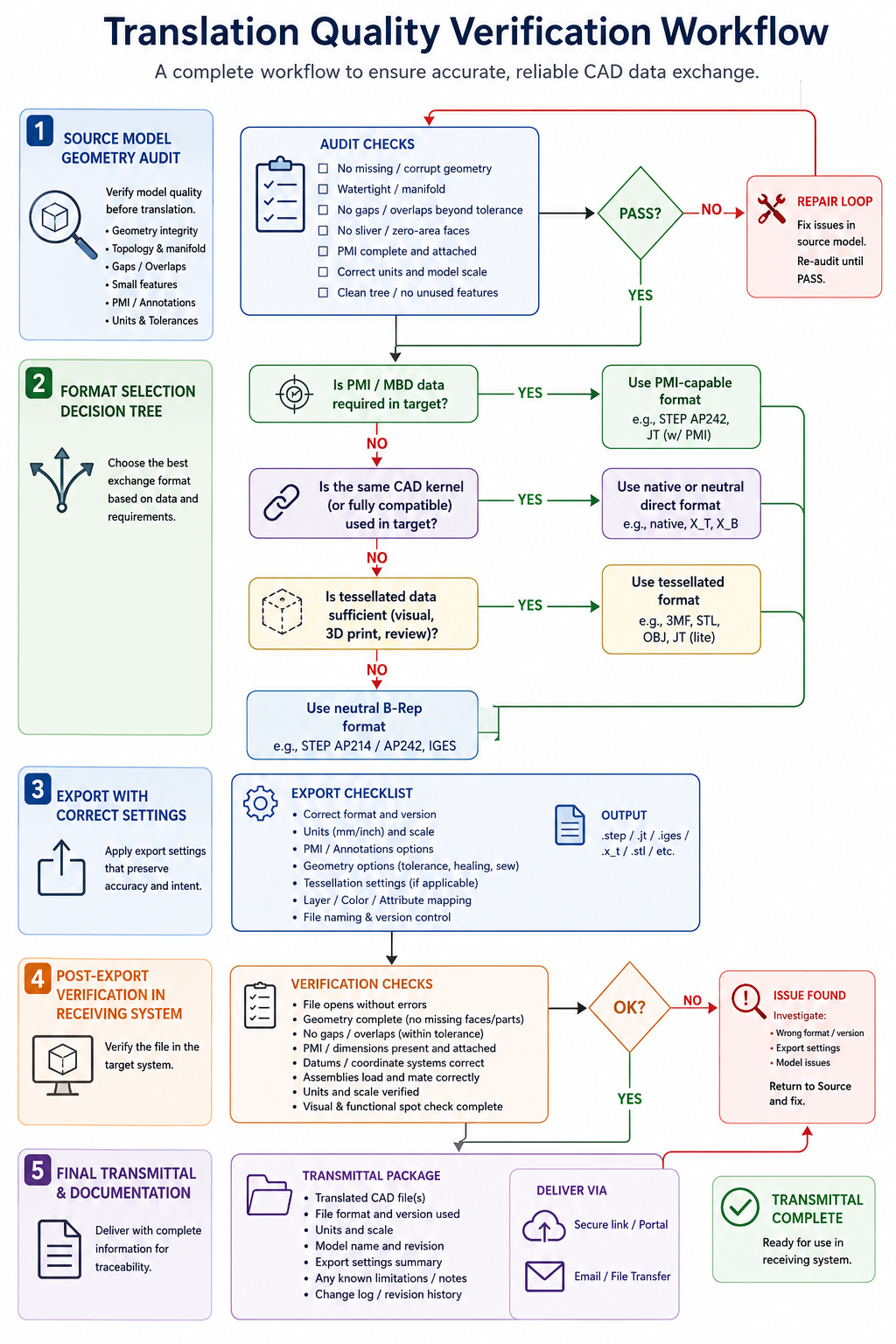
Pre-Export Checklist for CAD Translation
PRE-EXPORT AUDIT - COMPLETE BEFORE EVERY TRANSLATION:

GEOMETRY QUALITY:
  [ ] Run geometry check tool - zero invalid geometry reported
  [ ] Verify model is a closed watertight solid (not a surface set)
  [ ] Check for non-manifold edges (must be zero)
  [ ] Verify no zero-thickness walls or degenerate faces
  [ ] Confirm all bodies intended for export are included

FORMAT SELECTION:
  [ ] Is PMI / GD&T required in the output? -> Use STEP AP242
  [ ] Is receiving system IGES-only? -> Clarify and push for STEP
  [ ] Is this for additive manufacturing? -> Use STEP + STL both
  [ ] Is this for CAM in a Parasolid system? -> Consider .x_t format

UNIT VERIFICATION:
  [ ] Confirm export units match the program's unit standard
  [ ] Verify unit header will be included in STEP output
  [ ] Note unit system in transmittal document to receiver

SIMPLIFICATION:
  [ ] Suppress thread cosmetics (not needed for solid exchange)
  [ ] Remove internal construction geometry
  [ ] Evaluate whether internal cavities are needed in output

PROTOCOL SETTINGS:
  [ ] STEP AP242 selected (not AP203 or AP214 for new programs)
  [ ] PMI export enabled if model contains annotations
  [ ] Assembly structure option enabled for multi-body/assembly
  [ ] Chord tolerance set appropriately for precision level needed

POST-EXPORT VERIFICATION:
  [ ] Open exported file in receiving system or neutral viewer
  [ ] Confirm solid body recognized (not surface set)
  [ ] Measure one reference dimension and verify against spec
  [ ] Confirm assembly structure intact (if applicable)
  [ ] Verify PMI visible and correctly associated (if applicable)
Geometry Healing: Tools and Techniques for Fixing Translated Geometry
When translated geometry arrives with errors despite a clean source model and correct export settings, the geometry healing process begins. Every professional CAD platform includes geometry healing tools, and several dedicated interoperability toolkits exist specifically for translation quality management. Understanding what these tools can and cannot fix helps set realistic expectations for the healing workflow.
Native Healing Tools by Platform
SolidWorks Import Diagnostics is the most accessible healing interface available in any major CAD platform. It runs automatically when a STEP or IGES file is imported and presents a report of faulty faces and open edges, with buttons to attempt automatic repair of each category. For small gaps and minor stitching failures, Import Diagnostics resolves the majority of errors without manual intervention. For larger gaps or more complex topology failures, it identifies the specific faces and edges that need manual repair through surface editing.
PTC Creo Geometry Repair provides a similar workflow but with additional tools for specifically addressing the types of errors common in Creo’s conversion from STEP and IGES. The Geometry Repair tool in Creo categorizes errors by type and allows targeted repair actions: close gaps, flip normals, remove short edges, and fill holes in surfaces. Creo’s repair tools are particularly effective for models exported from non-PTC systems that experience edge tolerance mismatches when imported into the CGM kernel.
Siemens NX Heal Geometry and Solid Edge’s equivalent provide automated healing with detailed reporting. NX’s healing tools are well-regarded for their ability to handle complex geometry from aerospace and automotive sources, which tend to involve the kinds of large, complex freeform surfaces where topology errors are most damaging.
Ansys SpaceClaim is frequently used as a dedicated geometry repair environment precisely because its direct modeling tools make it fast to manually repair faces and edges that automated healing tools cannot resolve. Engineers receive a broken STEP file, open it in SpaceClaim, use the repair tools for automated fixes, then switch to direct face editing for the remaining issues, and export a clean STEP or Parasolid file for use in the final application.
Dedicated Interoperability Tools
For organizations that handle large volumes of translated geometry or that require certified translation quality for regulated industries, dedicated CAD interoperability toolkits provide capabilities beyond what CAD platform healing tools offer. Spatial’s 3D InterOp SDK, CADfix from ITI, and TransMagic provide translation and healing workflows that detect and correct over 150 defect types, generate detailed quality reports, and in some cases certify that translated geometry meets specific geometric accuracy standards.
These tools are particularly valuable in aerospace and automotive supply chains where a supplier’s ability to deliver verified-quality CAD data to a customer is a contractual requirement. A company using TransMagic or CADfix can provide a geometry quality certificate with every file they deliver, documenting the translation errors detected and the corrections applied. This transforms translation quality from an engineering workflow concern into a documented, auditable data quality process.
When Healing Is Not Enough: Rebuilding From Scratch
There are classes of translation errors that no healing tool can resolve: cases where the source model contains fundamental geometric problems that produce invalid topology regardless of how the translation is tuned or how thoroughly the received geometry is healed. In these cases, the correct decision is to request the source model from the sender and ask them to fix the source geometry before re-exporting, or to rebuild the affected geometry from scratch using the translated file as a reference rather than attempting further healing.
The decision point is when the time invested in healing exceeds the time to rebuild: typically when more than 20 percent of the faces in the model require manual repair. Rebuild the geometry by creating new surfaces or solids that reference the geometry of the damaged model visually, using the coordinates and dimensions from the original model’s specification as the driving values rather than the broken face geometry as the reference. This produces cleaner geometry than aggressive healing and typically takes comparable time to a thorough healing attempt on a severely damaged model.
Translation in the Modern Engineering Workflow: Supplier Communication and MBD
CAD data translation does not happen in isolation. It sits within a broader engineering communication workflow that determines how data flows between design, manufacturing, quality, suppliers, and customers. Understanding where translation fits in that workflow, and how to design the workflow to minimize translation-introduced errors, is the strategic layer above the technical fixes covered in earlier sections.
Designing the Supplier Communication Workflow Around Translation Constraints
Most supplier communication workflows evolved around PDF drawings because PDFs are universally readable, they carry 2D annotation data completely and without loss, and they do not require the recipient to have a CAD license. The challenge is that PDF drawings are a one-way, non-parametric communication medium: the supplier sees the drawing but cannot use the 3D geometry for CAM programming, inspection planning, or simulation without separately receiving a 3D file.
Best practice for supplier communication in 2026 combines three file types: the STEP AP242 file for geometry and PMI, the 3D PDF for stakeholders who need to view the model without CAD software, and the 2D drawing PDF as a redundant reference for inspection and fabrication contexts where the 2D format is preferred. This combination ensures that every recipient has the data they need in the format they can use, while the STEP AP242 file carries the authoritative geometry and PMI for manufacturing and inspection purposes.
Model Based Definition and the Future of Translation
Model Based Definition (MBD) is the practice of using the 3D CAD model as the authoritative definition of the product, replacing or significantly reducing the role of 2D drawings. MBD is increasingly mandated in aerospace (Boeing, Airbus, and major defense primes have adopted it), automotive (IATF 16949 explicitly supports MBD workflows), and medical device manufacturing (FDA guidance supports electronic design records).
The translation challenge in an MBD workflow is more significant than in a drawing-based workflow because the model must carry all manufacturing information that was previously on the drawing: not just geometry but GD&T, surface finish, material specifications, and process notes. This requires STEP AP242 with full semantic PMI export, correct configuration of the receiving system’s AP242 PMI reader, and a verification step at the receiving end that confirms PMI was received correctly before manufacturing or inspection activities begin.
As MBD adoption grows, the ability to reliably translate semantic PMI between CAD systems becomes a competitive differentiator for engineering organizations and their supplier chains. Suppliers who can receive and process semantic PMI directly from customer STEP files can automate their CMM programming, first article inspection, and SPC data collection, reducing their internal cost and improving their delivery reliability. This capability starts with understanding and correctly implementing the translation workflow covered in this article.
Frequently Asked Questions
Q: What is the best CAD format for exchanging files between different CAD systems?
STEP AP242 is the current industry standard for exchanging solid 3D geometry between different CAD platforms. It preserves solid B-Rep geometry with full topological integrity, assembly structure, and PMI/GD&T annotations when the exporting system supports AP242 PMI export. Use STEP AP242 for all new engineering data exchange programs. IGES should only be used when the receiving system does not support STEP, which is very rare for any software in active maintenance. For systems that share the same geometry kernel (such as two SolidWorks installations sharing the Parasolid kernel), native kernel format exchange provides better geometry fidelity than STEP for pure geometry without annotation data.
Q: Why do I get open edges and surface gaps after importing a STEP file?
Open edges occur when the geometric tolerance of the receiving CAD system’s kernel differs from the sending system’s kernel. Edges that were coincident within the sending system’s tolerance may fall outside the receiving system’s stitching tolerance, producing gaps that did not exist in the source model. The fix is to run the receiving system’s geometry healing tool (Import Diagnostics in SolidWorks, Geometry Repair in Creo, Heal Geometry in NX) to stitch the gaps closed. For persistent gaps, the sending engineer should run a geometry check on the source model before export and ensure the source geometry contains no pre-existing surface quality issues that the translation has revealed.
Q: What is the difference between STEP AP203, AP214, and AP242?
AP203 carries solid B-Rep geometry and basic assembly structure with no color or annotation data. AP214 adds color, layer data, and partial GD&T support, and is widely used in automotive supply chains. AP242 is the current comprehensive standard that adds full semantic PMI and GD&T support compliant with ASME Y14.5 and ISO 1101, composite material definitions, and kinematics data. For any program that uses Model Based Definition or requires GD&T data to survive translation, AP242 is the only appropriate choice. For programs where geometry alone is sufficient, AP214 is acceptable but AP242 is preferable as the forward-compatible choice.
Q: How do I fix a unit system error in a translated CAD file?
If a model was exported in millimeters but imported as inches (or vice versa), all dimensions will be wrong by a factor of 25.4. The fix depends on your CAD platform: in most systems you can re-import the file with an explicit unit override that specifies the correct source units, which applies the 25.4 scale correction automatically. Alternatively, scale the entire imported geometry by 25.4 (or 1/25.4) to convert from the wrong unit to the correct one. To prevent this error: verify that the exported STEP file includes a unit header (it should by default in any modern exporter), and measure one reference dimension immediately after any import to confirm it matches the known specification before proceeding with any downstream work.
Q: What is non-manifold geometry in CAD and why is it a problem?
Non-manifold geometry is a topological condition in a solid model where edges are shared by more than two faces, where zero-thickness walls create coincident face pairs, or where T-junctions exist within the surface structure. Non-manifold geometry is mathematically invalid as a solid because it cannot unambiguously define an interior volume. It blocks virtually all downstream engineering operations: FEA meshing fails, CAM toolpath generation fails, interference checking produces false results, and 3D printing slicers cannot generate valid layer boundaries. Non-manifold geometry almost always originates in the source model and is exposed by translation. The correct fix is to repair the source model and re-export, not to attempt repair of the translated file.
Q: What is semantic PMI and why does it matter for manufacturing?
Semantic PMI is the machine-readable structured data representation of GD&T and manufacturing annotations in a 3D model, as carried by STEP AP242. Unlike graphical PMI (which is just a visual display of the annotation), semantic PMI encodes the geometric characteristic type, tolerance value, datum references, and associated geometry in a way that downstream software can read and process automatically. CMM programming software that reads semantic PMI can automatically generate inspection routines. SPC systems can automatically collect tolerance data. CAM systems can identify critical surfaces. Without semantic PMI, every downstream team must manually re-enter annotation data from a 2D drawing or visual model inspection, creating both labor overhead and a risk of data entry errors in the manufacturing record.
Q: What tessellation chord tolerance should I use when exporting STL for 3D printing or CNC?
Set the chord tolerance to one-tenth of the tightest manufacturing tolerance in the model. For standard FDM 3D printing with 0.2mm layer height, a chord tolerance of 0.02mm is appropriate. For SLA or SLS printing at finer resolution, use 0.005mm to 0.01mm. For CNC reference geometry on standard tolerance parts (plus or minus 0.1mm), use 0.01mm chord tolerance. For precision bores at H7 tolerance (approximately plus or minus 0.02mm on a 25mm bore), use 0.002mm chord tolerance to ensure the tessellated geometry does not introduce dimensional error that falls within the tolerance band. The default chord tolerance in most CAD systems is set for visual quality, not manufacturing precision, and should never be used for precision manufacturing exports without review.
Conclusion:
CAD data translation is not an IT function or a file management task. It is an engineering process with measurable quality outcomes that directly affect manufacturing cost, schedule, and product integrity. A translated model with surface gaps that reach a CAM system produces incorrect toolpaths. A STEP file exported as AP203 from an MBD model silently discards all GD&T data that the manufacturing team needs. A tessellated STL file with default chord tolerance introduces dimensional errors that fall within the tolerance bands of precision features.
Every one of these failures is preventable with the systematic application of the knowledge in this article: choosing the right format and protocol for each use case, running the geometry audit before export, configuring the export settings correctly, verifying the output in the receiving system, and applying geometry healing to any errors that survive the process. None of this requires expensive specialized software. It requires deliberate process design applied consistently to every data exchange in the team’s workflow.
The broader implication is that as Model Based Definition adoption grows and 3D models increasingly replace 2D drawings as the authoritative definition of products, translation quality becomes more important, not less. When the model is the drawing, a model that arrives at the supplier with missing PMI or degraded geometry is not just an inconvenience. It is a breakdown in the engineering definition of the product, with consequences that propagate from the supplier’s shop floor into the product’s quality and the organization’s liability.
Build the pre-export checklist into your team’s data release workflow. Make the post-import verification a mandatory step before any translated geometry is used in manufacturing or quality activities. Document which translation paths in your organization require kernel-level exchange rather than STEP. And ensure that everyone who sends and receives CAD data understands what each format can and cannot carry, so that the choice of format is deliberate rather than defaulted.
Most engineers learn the hard way that the decisions made during CAD modeling determine the majority of a product’s production cost. Not the decisions made on the factory floor, not the choices made during production planning, not the negotiations with suppliers. The modeling decisions. The geometry of each part. The number of fasteners. The direction each component inserts into the assembly. The presence or absence of locating features. These choices, made by an engineer in front of a screen weeks or months before a single unit is built, lock in somewhere between 70 and 80 percent of the total production cost before manufacturing has been given any input at all.
Design for Assembly (DFA) is the discipline of making those modeling decisions deliberately, with the assembly process in mind. Its roots trace to the formal methodology developed by Dr. Geoffrey Boothroyd and Dr. Peter Dewhurst at the University of Rhode Island in the early 1980s, which gave manufacturing engineering its first rigorous, quantifiable method for evaluating and improving assembly efficiency at the design stage. Four decades later, the core principles remain as relevant as ever, and modern CAD tools have made them faster to apply than at any previous point in history.
The gap between what DFA says and what most engineering teams actually do in their CAD models remains wide. The principles are known. The benefits are documented in hundreds of industry case studies. But most teams apply them inconsistently, late, or not at all, usually because no one has translated the methodology into the specific CAD modeling actions that implement each principle in practice.
This article closes that gap. Each principle is explained with the precision it deserves, connected to the specific CAD modeling technique that implements it, and grounded in the real production cost consequences of getting it right or wrong. The result is a resource that engineering teams can use immediately in their active design work, not after a DFA training course, not during a production debrief, but at the keyboard while the model is still being built.
Why Assembly Cost Is a CAD Problem, Not a Manufacturing Problem
The single most important concept in Design for Assembly is also the one most consistently misunderstood: assembly cost is determined by design decisions, not by assembly operations. Once a design is released to manufacturing, the assembly team can optimize their process, refine their tooling, train their workers, and implement lean principles, but they cannot change the fundamental cost structure that the design has locked in. They can only execute the assembly that the design requires.
This is why DFA must happen in the CAD environment, during the design phase, while changes are cheap. The cost of changing a part geometry in a CAD model is measured in engineer-hours. The cost of changing a part geometry after tooling has been cut is measured in tens of thousands of dollars and weeks of delay. The cost of discovering an assembly inefficiency during production ramp-up is measured in labor variances, yield losses, and missed launch targets.
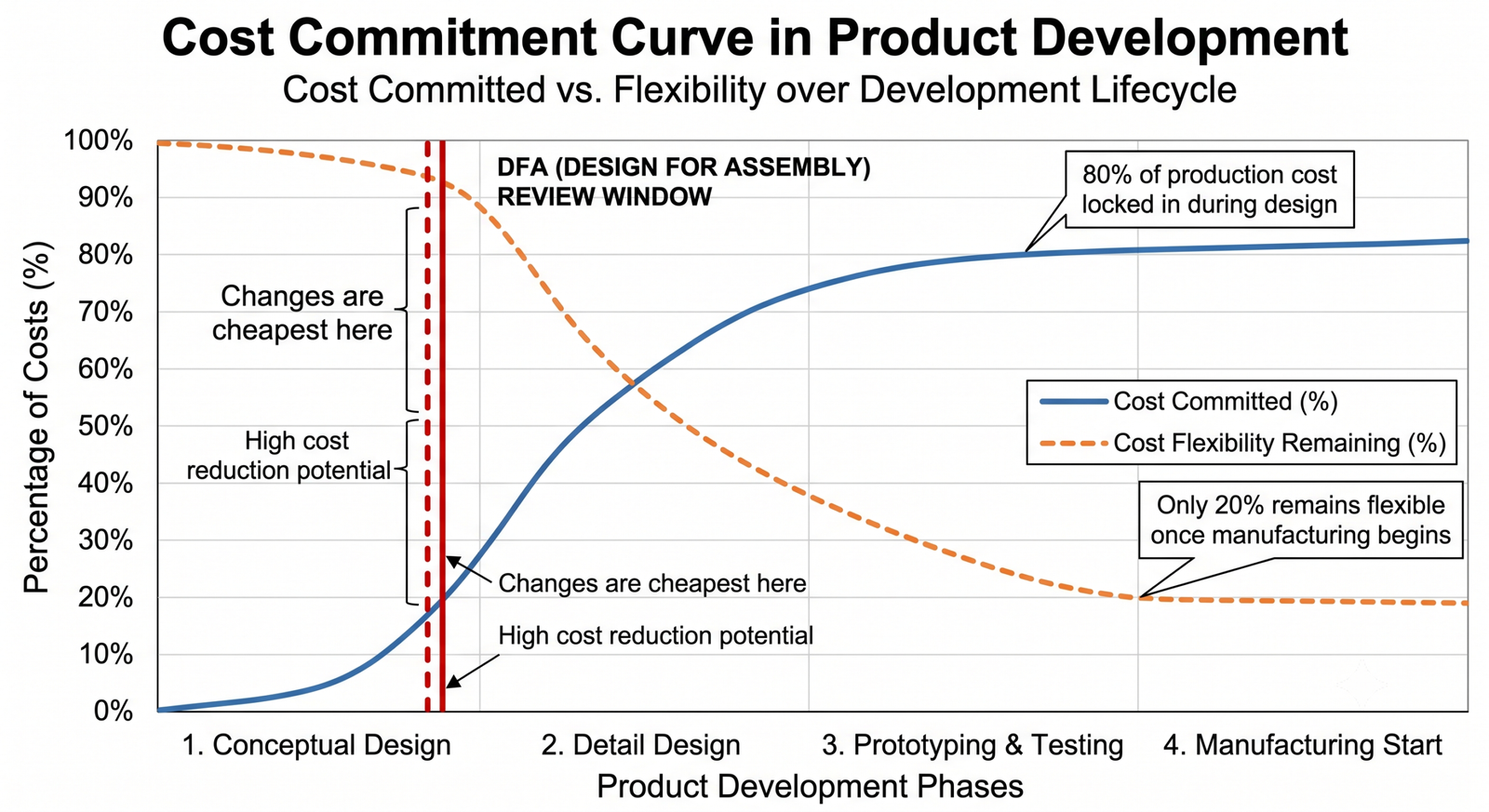
The 80 Percent Cost Lock-In Reality
The figure cited most often in design economics literature is that approximately 80 percent of a product’s total cost is determined during the design phase. The specific percentage varies by product type and industry, but the directional truth is consistent across virtually every product category: the majority of manufacturing cost is embedded in the design before manufacturing has started.
This is not an abstract principle. It has a direct, mechanical explanation. Production cost is determined by part count (more parts equal more assembly operations), part geometry (complex geometry means complex tooling and handling), fastener count (every fastener is an insertion, torque, and verification operation), and assembly sequence complexity (more steps mean more opportunities for error and more labor time). Every one of these cost drivers is a direct output of CAD modeling decisions.
The DFA Efficiency Ratio: A Number Every Designer Should Know
The Boothroyd-Dewhurst methodology introduced a quantitative metric called the DFA efficiency ratio, which provides a numerical score for how efficiently a design can be assembled. The ratio is calculated by dividing the theoretical minimum assembly time (based on the minimum number of parts, each taking approximately three seconds to assemble perfectly) by the actual estimated assembly time for the current design.
A product with a DFA efficiency ratio of 30 percent is using only 30 percent of its theoretical assembly potential. The remaining 70 percent is being consumed by unnecessary parts, inefficient insertion operations, complex fastening sequences, and handling difficulties that could be eliminated through design changes. Most first-pass designs have efficiency ratios in the range of 15 to 35 percent. Products redesigned with DFA principles typically achieve ratios of 50 to 70 percent, representing a proportional reduction in assembly cost.
For a team that has never calculated their DFA efficiency ratio, the exercise alone is valuable: it quantifies the gap between the current design and its theoretical optimum and gives leadership a number-based justification for the time invested in DFA review.
Industry Data Point A published Boothroyd-Dewhurst case study on a pedestrian traffic light controller showed that applying DFA methodology reduced assembly time from 758 seconds to 319 seconds per unit, a reduction of more than 57 percent, while cutting assembly cost by more than 82 percent. The part count reduction from the redesign was the primary driver of both improvements. This scale of improvement is not exceptional in DFA work. It is typical.
The Minimum Part Criteria: The Most Powerful DFA Tool in Your Hands
Before any other DFA technique, before any discussion of fastener reduction or self-locating features, there is one question that every part in every assembly must answer. It is the foundation of the Boothroyd-Dewhurst methodology and the single most cost-impactful tool available to a design engineer applying DFA principles.
The minimum part criteria test asks three questions about each part in an assembly. If the part cannot answer yes to at least one of the three questions, it is a candidate for elimination or combination with another part. The three questions are:
Does the part move relative to all other parts already assembled? Motion that is fundamental to the function of the product (a rotating shaft, a sliding mechanism, a pivoting lever) is a legitimate reason for a part to exist separately. Motion that is incidental or could be achieved through a different design (a separate cover that opens rather than being designed as a snap-on integrated feature) is not.
Must the part be made of a different material than adjacent parts? Electrical insulation, thermal isolation, chemical resistance, or structural requirements that cannot be met by the same material as the surrounding parts justify a separate part. Cosmetic differences in material appearance generally do not.
Must the part be separate to allow assembly of other parts? Some parts must be separate because their presence would prevent the assembly of everything else: a fastener that secures two halves together, a retaining ring that locks a shaft in position. If removing the part would make the rest of the assembly impossible, it justifies its existence. If the assembly could proceed equally well with the function integrated into an adjacent part, it does not.
Applying the Minimum Part Criteria in Your CAD Assembly
The practical way to apply this test is to open the assembly model and work through the BOM systematically, asking the three questions about every component. This is not a theoretical exercise: it requires looking at the 3D model and understanding the functional purpose of each part in the context of the complete assembly.
Parts that fail all three criteria are primary targets for elimination or combination. The CAD action is direct: use multi-body modeling or part consolidation to merge the function of the eliminated part into an adjacent component. Model the consolidated part, verify that the combined component can still be manufactured by the intended process, and update the assembly.
Parts that are borderline, where the answer to one of the three questions is uncertain, are targets for creative redesign. A part that might need to be separate because of its material requirement deserves a design question: could the same material serve both parts, or could a material change to one of them resolve the conflict? This kind of design question, prompted by the minimum part criteria test, often leads to more innovative solutions than the original design contained.
Real Application A precision instrument manufacturer applied the minimum part criteria to a sensor mounting assembly with 23 components. Seventeen of those components failed all three criteria tests. After consolidation and elimination, the redesigned assembly used 9 components. Assembly time dropped by 61 percent. The redesigned parts were more complex individually but simpler collectively, and the manufacturing cost of the 9 complex parts was lower than the manufacturing and assembly cost of the original 23 simple ones.
The True Cost of a Fastener: Why Every Screw Deserves Scrutiny
Nothing in DFA has a greater cost impact per unit than the decision to use a fastener. Engineers and product managers often focus on the procurement cost of fasteners, which is typically small, and miss the far larger system cost that every fastener generates. A fastener is not a ten-cent item. It is a ten-cent item surrounded by fifteen to forty-five dollars of associated costs that accumulate through the entire production process.
Cost Element
Description
Typical Cost Multiplier vs Part Cost
Part procurement
Purchasing the fastener itself
1x (base cost)
Inventory carrying
Stocking, tracking, reordering
0.25x to 0.5x per year
Hole preparation
Drilling, tapping, counterboring
2x to 5x part cost
Insertion labor
Manual or automated placement
3x to 10x part cost
Torquing and verification
Torque wrench, click or electronic
2x to 4x part cost
Inspection and rework
Missed fasteners, cross-threading
5x to 20x (per defect)
Assembly tooling
Fixtures, bit sets, torque tools amortized
0.5x to 2x part cost
Documentation
Assembly instruction authoring per fastener step
1x to 3x part cost
Total system cost per fastener
Sum of all above elements
15x to 45x part price
The table above illustrates why DFA methodology treats fastener elimination as one of the highest-priority cost reduction opportunities in product design. The part cost of a standard M5 socket cap screw might be eight cents. The total system cost of that screw, including hole preparation, insertion, torquing, verification, tooling amortization, and the portion of assembly instruction authoring attributable to that step, commonly reaches several dollars per unit. Multiply by the fastener count per product and by the annual production volume, and the cumulative cost of fasteners across a product’s lifecycle becomes a significant financial target.
Fastener Reduction Strategies and Their CAD Implementation
Snap-fit joints are the most common fastener replacement strategy in injection-molded plastic components. A cantilever snap-fit is a feature integrated directly into one of the mating parts: a flexible arm with a catch geometry that deflects during assembly and springs back to lock the joint. Designing effective snap-fits in CAD requires attention to the arm length, thickness, and deflection angle, as well as the catch geometry and the retention force. Most CAD platforms include simulation tools for snap-fit deflection analysis.
Press-fit and interference-fit joints eliminate fasteners for components that require permanent or semi-permanent assembly. A shaft pressed into a bore, a bearing pressed into a housing, an insert pressed into a plastic molding. The CAD design requires precise specification of the interference value, which must account for both parts’ dimensional tolerances and material modulus. Typical metal-to-metal interference fits specify between 0.01 and 0.05 mm of interference depending on diameter and application.
Integral hinge features replace separate hinge hardware in plastic and thin-sheet metal designs. A living hinge in a plastic part is a thin section connecting two thicker sections, flexible enough to bend repeatedly without fracture. Designing a living hinge in CAD requires specifying the hinge thickness (typically 0.3 to 0.5 mm for polypropylene), the hinge width, and the mold geometry that produces a consistent cross-section along the full hinge length.
Clinching and self-piercing rivets replace bolted joints in sheet metal assemblies where access for tightening is limited. These cold-forming operations create permanent joints without heat or consumables. CAD design requirements include specifying the minimum sheet thickness for the process, the edge distances from the clinch point, and the clearance for the tool head in the assembly.
Welding and adhesive bonding are appropriate replacements for fasteners when the joint is permanent and the materials are compatible. Designing for welding requires attention to joint accessibility for the welding process, minimum material thickness for the process, and the weld bead geometry that can be inspected after joining.
When Fasteners Are the Right Answer
DFA does not mean zero fasteners. It means every fastener is justified. Fasteners remain appropriate when the joint must be serviceable (accessible for disassembly and reassembly during maintenance), when material combinations make bonding or forming joints impractical, when the joint must transmit specific loads that integral features cannot reliably handle, or when regulatory requirements mandate bolted connections with torque verification for safety-critical joints.
The discipline is to make this justification explicit during design review. For every fastener that remains in the design after a DFA review, the engineer should be able to state which of these conditions it satisfies. A fastener whose presence cannot be justified by functional necessity is a candidate for elimination regardless of how conventional its use may seem.
Top-Down Assembly Direction: The One Principle That Transforms Assembly Lines
Of all the geometric principles in DFA, the assembly direction principle has the most direct and measurable impact on production line efficiency. It is also the one that is most consistently violated in product designs that were modeled without assembly process in mind.
The principle is simple: all components should insert into the assembly from the same direction, ideally from above along the vertical axis, using gravity as an assembly aid rather than working against it. When every part drops or slides into position from above, the assembly line can be optimized for a single-direction workflow. Fixtures are simpler. Automation is feasible. Operators develop consistent, repeatable motions. Inspection can verify the complete assembly state at each stage with a single visual check.
What Violations of the Assembly Direction Principle Look Like
Violations of the top-down assembly principle are easily identified in the CAD model: any component that requires a horizontal insertion, an upward insertion against gravity, or a rotation during insertion is a violation. Any fastener that must be accessed from the bottom of an assembly is a violation. Any subassembly that must be inverted at any point during the assembly sequence is a violation.
These violations are modeled into the design when engineers focus on the product’s functional geometry without considering the sequence of operations required to assemble it. A side-entry connector that is functionally equivalent to a top-entry connector but requires a different insertion direction, a bottom-mounted PCB that requires flipping the chassis, a horizontal cross-bolt that could be replaced by a vertical fastener, all of these are assembly direction violations that add cost with no functional benefit.
Auditing Assembly Direction in Your CAD Model
The CAD model makes this audit straightforward. In your assembly model, create a rendering or screenshot with the nominal assembly orientation (the orientation in which the product would sit on the assembly line). Then review every component’s insertion path:
Does the component insert from above? Green light.
Does the component insert horizontally? Evaluate whether the geometry can be redesigned to allow top-down insertion.
Does the component insert from below? This is the most expensive violation. Redesign for top-down access is strongly recommended.
Does the component require rotation during insertion? Model the rotation motion in the assembly to quantify the access space required and the operator motion involved.
Most CAD assembly tools allow you to define assembly sequences and animate the assembly process. Using this animation to verify insertion direction is one of the fastest ways to identify direction violations before they reach the shop floor.
Designing the Assembly Sequence Into the CAD Model
Beyond auditing insertion directions, experienced DFA practitioners design the assembly sequence into the CAD model explicitly. This means creating exploded views that represent the assembly sequence step by step, with each step showing one insertion operation in the correct direction. Exploded view drawings that are generated from the CAD model serve double duty: they communicate assembly intent to the production team and they force the design engineer to mentally rehearse the assembly process during the design phase, catching direction violations before they are molded into physical tooling.
Self-Locating and Self-Aligning Features: Eliminating Positioning Labor
Positioning and locating parts during assembly is invisible labor. It happens at every assembly step, takes time, introduces variability, and is almost never captured in standard time studies. An assembler who picks up a component and spends three seconds rotating it, translating it, and visual-checking its position before seating it is performing positioning labor that does not appear in the assembly work instruction but contributes directly to cycle time and quality risk.
Self-locating features built into CAD geometry eliminate this positioning labor by making the correct assembly position the only position the part can occupy. The part drops into position, guided by its own geometry, and requires no visual positioning check because the geometry itself provides the confirmation of correct placement.
Types of Self-Locating Features and Their CAD Implementation
Locating pins and mating holes are the most common self-locating feature pair. A cylindrical pin on one part mates with a corresponding hole on the adjacent part. The pin diameter and hole diameter are specified with a clearance fit that allows insertion without jamming while providing positioning accuracy. For most applications, a locational clearance fit (H7/h6 tolerance class) provides the right balance between ease of insertion and positional repeatability.
Mating bosses and recesses provide location in two axes simultaneously. A rectangular boss on one part seats in a corresponding rectangular recess on the mating part, locating the component laterally in both the X and Y directions simultaneously. Chamfers or lead-in radii on the boss edges guide the component into position during insertion, reducing the precision required of the assembler’s hand placement.
Shoulder steps and rabbet joints provide location in the assembly direction as well as in the plane perpendicular to it. A stepped shoulder on one part seats against a corresponding step on the mating part, providing a positive stop in the assembly direction and lateral location simultaneously. This feature type is common in optical and electronic assemblies where component positioning must be precise in all three dimensions.
V-groove and cone features provide self-centering location for circular components. A conical lead-in on a shaft end guides the shaft into a matching bore without requiring the assembler to align the shaft precisely before insertion begins. The cone geometry converts lateral misalignment into a guided insertion motion, reducing insertion difficulty significantly for components that must be assembled without visual access to the mating bore.
The Clearance Fit Balance in Self-Locating Design
Self-locating features must balance two competing requirements: tight enough clearances to provide useful positional accuracy, and loose enough clearances to allow easy insertion without jamming. The correct clearance depends on the positional accuracy required by the function of the part and the manufacturing tolerances achievable for the locating features.
A common error is specifying self-locating features with clearances appropriate for a precision measurement instrument in a product that only requires assembly-level positional accuracy. The result is expensive tight-tolerance machining on locating features that do not need to be precise, adding manufacturing cost without improving function. Calculate the required positional accuracy from the functional requirements, specify the minimum clearance that achieves that accuracy, and do not tighten the tolerance further without a specific functional justification.
Poka-Yoke in CAD: Designing Out the Possibility of Mis-Assembly
Poka-yoke is a Japanese manufacturing term meaning mistake-proofing. In the context of DFA and CAD modeling, it refers to designing geometric features into parts that make incorrect assembly physically impossible. A part that can only be assembled in one orientation cannot be assembled backwards. A connector with a polarizing key cannot be plugged in reversed. A cover with an asymmetric boss pattern cannot be installed on the wrong side.
Poka-yoke is one of the highest-value DFA investments because it eliminates an entire category of quality cost: mis-assembly detection and rework. When a part cannot be assembled incorrectly, there is no need to inspect for incorrect assembly, no rework when incorrect assembly is detected, and no field return when incorrect assembly escapes into a shipped product.
Designing Asymmetry as a Mistake-Proofing Tool
The most straightforward poka-yoke technique is deliberate asymmetry. A symmetric part can always be assembled in multiple orientations. If not all of those orientations are correct, the symmetric design is an assembly error waiting to happen. The CAD fix is to introduce asymmetry that makes the correct orientation geometrically unique.
This asymmetry can be subtle: an off-center boss, a chamfer on one corner but not the others, a hole shifted slightly from the centerline. It does not need to be large enough to change the visual appearance of the part significantly. It only needs to be large enough that the part physically cannot be seated correctly in the wrong orientation. The assembly operation itself becomes the test: if the part seats correctly, it is correctly oriented.
Keying and Polarizing Features in CAD
Keyed joints are poka-yoke features for rotational components. A key on a shaft mating with a keyway in a hub ensures that the hub can only be installed in the designed angular orientation. This is functional as well as mistake-proofing: the key transmits torque, so its presence is justified by the minimum part criteria. The poka-yoke benefit comes for free as part of the functional design.
Polarizing keys for electrical connectors follow the same principle. A polarizing rib on one half of a connector body mates with a corresponding groove on the other half, preventing incorrect orientation of the mating connector. Designing this feature into the CAD model requires attention to the rib geometry, the mating clearance, and the interference with adjacent connector bodies if multiple connectors are present in close proximity.
Part Numbering and Color Coding as Poka-Yoke
Physical poka-yoke extends to documentation and visual management. Parts that are visually similar but functionally different are a persistent source of assembly errors. Two O-rings of slightly different diameters, two springs with different stiffnesses, two PCBs with different firmware, cannot be distinguished at the assembly station without deliberate design intervention.
The CAD-level response is to design visible differentiation into similar parts wherever possible: different colors specified in the model appearance settings and called out on the drawing, dimensional differences large enough to be visible without measurement, or part marking requirements (laser etching, embossed part numbers) designed into the model geometry. The assembly instruction, generated from the CAD model, calls attention to the difference at the step where the correct part must be selected.
Part Standardization: The Supply Chain DFA Dividend
DFA is most commonly discussed as a part count and assembly time problem. Its impact on the supply chain is equally significant but receives far less attention. Every unique part in a product requires its own procurement relationship, its own incoming inspection protocol, its own storage location, its own reorder point calculation, and its own obsolescence management. The administrative cost of part variety is a real and substantial component of total product cost.
Part standardization reduces this cost by consolidating variety: using one common fastener size across an entire product family rather than five different sizes, using one standard bearing type wherever bearing interfaces appear, using one O-ring compound and one set of standard sizes rather than specifying custom seals for each application. Every part that can be standardized reduces the supply chain complexity that the organization must manage.
Building a Standard Parts Library in CAD
The most effective way to enforce part standardization at the design level is through a standard parts library within the CAD environment. A library of approved standard components, fasteners, bearings, seals, connectors, and hardware, configured in the CAD tool as drag-and-drop components with pre-defined parameters, makes selecting a standard part faster than creating a custom one. When the path of least resistance is to use a standard part, most engineers will take it.
Building this library is a team-level investment: it requires agreement on which standard parts are approved, collaboration with procurement to verify that approved parts are reliably available, and maintenance of the library as standards evolve. But the investment is repaid every time an engineer reaches for the library instead of specifying a new custom component. In a team of ten engineers, the library saves hours per week in aggregate and prevents the supply chain complexity that custom parts generate.
Standardizing Interfaces, Not Just Parts
Beyond standardizing individual parts, DFA at the platform level means standardizing the interfaces between parts: the bolt patterns, the pilot diameters, the connector pinouts, the mounting feature envelopes that define how components attach to each other. When interfaces are standardized, components become interchangeable: a replacement sensor that fits the same mounting interface as the original requires no chassis modification. An updated motor with the same shaft diameter and keyway specification drops into the same assembly without change.
This kind of interface standardization is the basis of product platform strategy: designing a family of products that share common interfaces, common structural elements, and common procurement items. The DFA benefit at the platform level is multiplicative: every assembly efficiency improvement made to a shared interface or common component applies to every product in the platform, not just to the one that was being designed when the improvement was made.
Designing for Automated Assembly: The Future-Proofing Dimension of DFA
Many engineering teams design for manual assembly and then discover later that the product cannot be economically automated when production volumes increase. Retrofitting a design for automated assembly after it has been released to production is expensive and time-consuming. Designing for both manual and automated assembly from the beginning, with no additional cost, is a DFA discipline that pays off when the automation decision is made.
Automated assembly systems, whether robotic pick-and-place, vibratory bowl feeding, or vision-guided placement, have specific geometric requirements that manual assembly does not. Parts that are not designed to these requirements cannot be economically fed, oriented, or placed by automation, regardless of how efficiently a human assembler can handle them.
Design Rules for Automation Compatibility
Part geometry must support reliable bowl feeding. Vibratory bowl feeders work by using the part’s geometry to self-orient it as it moves along the feeder track. Parts must be stable in at least one preferred orientation and must not tangle with each other in bulk storage. Thin, flexible parts, parts with hooks or protrusions that interlock, and parts with no stable flat reference surface cannot be reliably bowl-fed. The CAD fix is to ensure that the part has a stable, flat surface for bowl-feeding orientation and no features that cause entanglement.
Part symmetry should be maximized or made completely functional. A part that is symmetric about all axes can be placed by an automated system in any orientation and it will always be correct. A part that is nearly symmetric but has a subtle asymmetric feature requires expensive vision-guided orientation correction. If functional asymmetry is required, make it obvious and large enough for reliable vision detection. If the asymmetry is not functionally required, remove it and design a poka-yoke feature into the mating part instead.
Insertion forces must be within robot gripper specifications. Press-fit and snap-fit joints that require large insertion forces may exceed the force capability of standard robotic end-effectors. Specify insertion forces in the design documentation and verify them against the planned automation system’s force capacity. High insertion forces are also more likely to cause part damage during automated assembly, so minimizing them improves both automation compatibility and part quality.
Compliant lead-ins are essential for blind assembly operations. When a robot cannot visually verify alignment before insertion, compliant geometry on the mating features guides the part into position despite small positional errors in the robot’s placement. Large chamfers (typically 30 to 45 degrees), generous radii on lead-in surfaces, and spring-loaded compliance mechanisms in the robot gripper work together to accommodate the positional uncertainty that all automated assembly systems exhibit.
Connecting DFA for Automation to CAD Tolerancing
The tolerances specified in the CAD model have a direct bearing on automation compatibility. Tight tolerances on locating features relative to the positional repeatability of the planned automation system create systematic assembly failures: the robot places the part, the tolerance is at the tight end, and the snap-fit or press-fit feature jams rather than engaging. Designing tolerances to accommodate the repeatability of the automation system, not just the functional requirement of the joint, is a DFA discipline that prevents costly automation debug after first-of-production builds.
The DFA CAD Checklist: A Pre-Release Audit for Every Assembly
The following checklist operationalizes all of the DFA principles covered in this article into a structured pre-release audit that any engineer can complete against their CAD assembly before design freeze. Each checkpoint is paired with the question that triggers it and the specific CAD action to take if the checkpoint is not passed.
DFA Checkpoint
Check
CAD Action if Failed
Each part passes minimum part criteria
Does it move? Different material? Must be separate?
Combine or eliminate the part
Part count is at or below DFA efficiency target
Count parts, calculate efficiency ratio
Identify lowest-efficiency parts first
No part requires two-hand insertion
Simulate one-handed handling in assembly model
Add lead-in, reduce mass, add grip feature
All parts insert from one direction (top-down)
Check all insertion vectors in assembly
Redesign to align insertion to Z-axis
Every fastener has been challenged
Can this joint use snap-fit, press-fit, or weld?
Replace fastener with integral joint feature
Self-locating features present on all parts
Do parts have pins, bosses, pockets to locate?
Add alignment features to mating parts
Poka-yoke geometry prevents all mis-assembly
Can this part be installed wrong?
Add asymmetry, key, or polarity feature
Standard fasteners only (where fasteners remain)
Are all fastener types from approved standard list?
Replace non-standard with closest standard
No blind assembly steps required
Can operator see every insertion?
Redesign for visual access during assembly
Simulation run for assembly sequence
Has DMU or motion study confirmed access?
Adjust geometry for tool and hand clearance
BOM reviewed for duplicate part numbers
Identical parts carry same part number?
Consolidate to single part, update BOM
Assembly instructions authored from CAD
Are instructions generated from model?
Create assembly exploded view in CAD
This checklist is most effective when it is applied before design freeze rather than after it. Apply it during detailed design, when the model is complete enough to audit but before tooling commitments have been made and before drawings have been released. The cost of acting on checklist findings during design is the engineer’s time. The cost of acting on the same findings after tooling release is an order of magnitude higher.
Frequently Asked Questions
Q: What is Design for Assembly (DFA) and why does it matter for CAD engineers?
Design for Assembly is the practice of designing products so that they are faster, cheaper, and more reliable to assemble. It was formalized by Dr. Geoffrey Boothroyd and Dr. Peter Dewhurst in the 1980s and remains one of the highest-ROI practices in product development. It matters for CAD engineers specifically because assembly cost is determined by design decisions, not manufacturing decisions. The geometry of each part, the number of fasteners, the insertion direction, the presence or absence of self-locating features: all of these are CAD modeling choices that lock in assembly cost before manufacturing has started. Applying DFA during modeling, not after release, is when the impact is greatest.
Q: What is the minimum part criteria test in DFA?
The minimum part criteria is a three-question test applied to every component in an assembly to determine whether it genuinely needs to be a separate part. The three questions are: Does it move relative to all other parts? Must it be made of a different material? Must it be separate to allow the assembly of other components? A part that cannot answer yes to at least one of these questions is a candidate for elimination or combination with an adjacent part. Applying this test systematically to every component in a design is typically the single highest-impact DFA activity.
Q: How does reducing part count reduce production costs?
Reducing part count reduces production cost through multiple simultaneous mechanisms. Fewer parts mean fewer assembly operations, reducing direct labor time. Fewer parts mean fewer procurement relationships, reducing supply chain administrative cost. Fewer parts mean fewer storage locations and lower inventory carrying cost. Fewer parts mean fewer interfaces where dimensional variation accumulates, reducing the probability of fit issues and rework. And fewer parts mean simpler assembly instructions, shorter operator training, and lower probability of assembly errors reaching finished goods.
Q: What are self-locating features in CAD and how do they reduce assembly cost?
Self-locating features are geometric elements designed into mating parts that guide each component into its correct assembled position automatically, without requiring the assembler to manually position and check alignment. Examples include locating pins and mating holes, mating bosses and recesses, shoulder steps and rabbet joints, and conical lead-ins on shaft ends. They reduce assembly cost by eliminating the positioning labor that assemblers perform at each step without it appearing in the assembly work instruction. They also improve quality by ensuring consistent positioning regardless of the individual assembler’s skill level.
Q: How does poka-yoke apply to CAD design?
Poka-yoke in CAD means designing geometric features that make incorrect assembly physically impossible. Deliberate asymmetry prevents symmetric parts from being installed in wrong orientations. Polarizing keys prevent connectors from being inserted reversed. Off-center boss patterns prevent covers from being installed on the wrong face. The value of poka-yoke features is that they eliminate an entire category of quality cost: mis-assembly detection, rework, and field returns caused by incorrectly assembled products. A part that cannot be assembled wrong needs no downstream inspection for incorrect assembly.
Q: What is the DFA efficiency ratio and how is it calculated?
The DFA efficiency ratio is a quantitative metric from the Boothroyd-Dewhurst methodology that measures how efficiently a design can be assembled. It is calculated by dividing the theoretical minimum assembly time (the minimum number of parts multiplied by approximately three seconds per part for a perfect assembly operation) by the estimated actual assembly time for the current design. A ratio of 30 percent means the design is using 30 percent of its theoretical assembly efficiency potential. Most first-pass designs score between 15 and 35 percent. DFA-optimized designs typically reach 50 to 70 percent. The ratio provides a quantifiable improvement target and helps prioritize which assembly steps to address first.
Q: How do you design for automated assembly in CAD?
Designing for automated assembly requires ensuring that part geometry supports reliable bowl feeding or vision-guided placement, that part symmetry is either maximized (so any orientation is correct) or made obviously asymmetric (so vision systems can reliably detect orientation), that insertion forces are within robotic end-effector specifications, and that compliant lead-in geometry accommodates the positional uncertainty of the robot. Tolerances on locating features must be specified relative to the positional repeatability of the automation system, not just the functional requirement of the joint. These design decisions should be made during CAD modeling using the automation system specifications as design inputs.
Conclusion:
Every principle covered in this article reduces production cost. None of them require special software. None require a dedicated DFA team or a separate methodology certification. They require an engineer in front of a CAD model who knows what questions to ask about each component and each joint before the design is released.
The minimum part criteria test takes an afternoon to apply systematically to a mature assembly design. The assembly direction audit takes an hour with the 3D model open. Adding self-locating features to critical interfaces takes a day. Challenging every fastener against the alternatives takes a design review meeting. None of these activities cost more than a fraction of what they save when they catch an assembly inefficiency that would otherwise be built into production tooling
What DFA ultimately requires is a change in the question engineers ask themselves while modeling. The default question is: does this design meet the functional requirements? The DFA question adds: and can it be assembled efficiently, reliably, and without error? Adding the second question does not make the first one harder to answer. It makes the first answer more valuable, because a design that is both functional and assembly-optimized is genuinely better than one that is functional alone.
The Boothroyd-Dewhurst research that formalized DFA methodology showed that the biggest gains come from the earliest interventions: changes made during concept design cost almost nothing and can eliminate entire categories of assembly cost. Changes made during detailed design cost engineer-hours but save tooling investment. Changes made after tooling release cost serious money. The CAD model, open on your screen right now, is the cheapest intervention point in that sequence.
Continue building your engineering design expertise with our guides on CAD modeling mistakes that delay manufacturing, multi-body modeling techniques, design tables for product families, and parametric modeling best practices.
There is a category of engineering task that consumes enormous amounts of time without anyone stopping to question it: the manual creation and maintenance of product variants. A bracket in five lengths. A housing in three wall thicknesses. A connector in eight pin counts. A structural beam in twelve cross-section sizes. Each variant follows the same design logic as the others. The geometry is identical except for a handful of dimensions. And yet, without design tables, most engineering teams build each one individually, maintain each one separately, and update each one manually whenever a shared specification changes.
The cumulative cost of this approach is staggering. For a product line with ten configurations, a single shared-dimension change that should take minutes becomes a half-day exercise in opening files, editing sketches, checking dimensions, saving, and verifying. When that same product line grows to fifty configurations over a product lifecycle, the manual approach becomes a full-time maintenance burden that crowds out the actual design work the engineering team was hired to do.
Design tables are the solution that most CAD platforms provide for exactly this problem, and they remain one of the most underutilized high-leverage tools in the typical engineering team’s toolkit. Not because engineers are unaware they exist, but because the full scope of what they enable, how they connect to drawings and BOMs, how they scale across assemblies, and how they bridge engineering to commercial product configuration, is rarely explained in its entirety in one place.
This article covers all of it. What design tables are and how they work across the major CAD platforms, where they deliver the most dramatic time savings in the development process, how to structure them for long-term maintainability, where they fail and why, and how leading engineering teams use them not just as a modeling efficiency tool but as a strategic product architecture decision.
What Design Tables Are and How They Actually Work
A design table is a spreadsheet-driven mechanism that controls multiple configurations of a CAD model from a single organized table. Each row in the table defines one configuration. Each column represents a dimension, parameter, feature state (suppressed or unsuppressed), or property value. Change a cell in the table, and the corresponding configuration updates automatically. Add a new row, and a new configuration is created instantly without touching the CAD model directly.
The core power of the design table is that it decouples the act of defining variants from the act of building geometry. You build the geometry once, structure it parametrically with named dimensions and configurable features, and then manage all variation through the table. The CAD model becomes a template. The design table becomes the product specification.
The Relationship Between Configurations and Design Tables
In most parametric CAD platforms, configurations are the native mechanism for storing multiple states of a model within a single file. A configuration is a saved snapshot of specific parameter values, feature suppression states, and appearance settings. Without a design table, configurations are created and managed individually through the CAD interface: right-click, add configuration, manually set each dimension, save.
A design table is a configuration manager. It does not replace configurations but drives them from a structured external or embedded spreadsheet. Every row in the design table creates, populates, and updates a configuration automatically. The result is that all your variant logic lives in a single, readable, shareable spreadsheet rather than being distributed across dozens of individual configuration dialogs inside the CAD model.
What a Design Table Actually Controls
The range of model properties that a design table can control is broader than most engineers realize. A well-structured design table can drive:
Linear and angular dimensions: length, width, height, diameter, radius, angle, thread pitch, depth
Feature suppression states: a boss that exists in some configurations but is absent in others, a hole pattern that appears only in certain variants
Sketch dimension values: the spacing between holes in a bolt pattern, the offset of a groove from a reference face
Custom properties: part number, description, material specification, finish, revision level, mass (calculated or overridden)
Appearance and display states: color, transparency, and visual representation for each configuration
Assembly-level component states: in assembly design tables, which components are included, suppressed, or replaced in each variant
The breadth of this control means that a single design table can fully define an entire product family, with every variant’s geometry, documentation properties, BOM line items, and visual presentation managed from one source.
Key Concept The design table is not a shortcut for generating quick variants. It is a product architecture decision. When you commit to a design table-driven approach, you are deciding that your product variants share a common parametric structure and that the table is the authoritative source for all variation. This decision has significant downstream benefits for BOM accuracy, drawing automation, and product configurability that extend well beyond the initial time savings in modeling.
Design Tables Across Major CAD Platforms
The design table concept exists in every major parametric CAD platform, but implementation details, capabilities, and best practices differ significantly. Understanding these differences helps you apply the approach correctly in your specific tool and helps teams that use multiple platforms understand how the concept translates across environments.
CAD Platform
Feature Name
Driver File
Scope
Key Strength
SolidWorks
Design Table
Microsoft Excel (.xlsx)
Parts and assemblies
Deep Excel integration, widely used, SOLIDWORKS 2026 family tables in drawings
PTC Creo
Family Table
Internal Creo table editor
Parts and assemblies
Verification instances, interchange groups, no Excel dependency
Autodesk Inventor
iPart / iAssembly
Internal spreadsheet editor
Parts and assemblies separately
Strong BOM automation, iMate support for auto-mating variants
CATIA V5/V6
Design Table
Microsoft Excel (.xls/.xlsx)
Parts, products, drawings
Supports formulas and relations driven from Excel, used in aerospace
Siemens NX
Spreadsheet-Driven Part
Microsoft Excel
Parts and assemblies
Integrated with Teamcenter PLM for variant BOM automation
Onshape
Configurations
Native table editor (cloud)
Parts and assemblies
No Excel dependency, live collaboration on configurations
SolidWorks Design Tables: Excel Integration in Depth
SolidWorks Design Tables are embedded Microsoft Excel worksheets stored directly inside the SolidWorks part or assembly file. This integration is both the feature’s greatest strength and its primary source of problems. The Excel integration means that anyone with Excel can read, understand, and in some cases edit the table without opening SolidWorks, which is genuinely useful for collaboration between engineering and commercial teams. It also means that Excel-specific issues, formula errors, linked external file problems, and version compatibility between Excel releases, can surface inside the CAD model in ways that are difficult to diagnose.
The auto-create function in SolidWorks Design Tables will automatically populate the table with all current model dimensions when first inserted, which is convenient for getting started but produces bloated tables when the model has many non-variant dimensions. Best practice is to use the blank option and manually add only the dimensions and parameters that genuinely vary between configurations, keeping the table lean and readable.
SolidWorks 2026 introduced Family Tables for drawings, which allows all configuration details and custom properties to be displayed directly on a drawing sheet in a formatted table. This is a significant advancement that directly reduces the time cost of documentation for multi-configuration parts, one of the historically weak points of configuration-driven workflows.
PTC Creo Family Tables: The Enterprise Approach
Creo Family Tables differ from SolidWorks Design Tables in an important way: they do not depend on Microsoft Excel. The table is managed entirely within the Creo environment using an internal editor. This eliminates the Excel-related failure modes that affect SolidWorks users and makes Creo Family Tables more robust in enterprise environments where Excel version management and file linking can be problematic.
Creo Family Tables also include a verification feature that checks each instance (the Creo term for a configuration) against the model to confirm it regenerates successfully before the table is committed. This automated verification is something SolidWorks users have to perform manually, and it prevents the common problem of silently broken configurations that only reveal their failure when the engineer actually needs to use them.
Interchange groups in Creo Family Tables allow interchangeable components to be defined at the table level, which has direct applications in design-to-order manufacturing where different supplier components can be substituted within the same assembly without creating separate assembly structures.
Autodesk Inventor iParts and iAssemblies
Inventor iParts handle part-level configurations while iAssemblies handle assembly-level configurations. The separation of concern is logical but means that cross-level variant management requires careful coordination between the part and assembly tables. Inventor’s approach includes strong BOM integration, where iPart configurations automatically generate distinct BOM line items with correct part numbers and descriptions, which is a significant time saver in the documentation phase.
iMates in Inventor allow connection points to be defined on iPart variants so that when a specific configuration is placed in an assembly, the correct mating relationships are applied automatically. This feature dramatically speeds up assembly modeling when working with families of standard components like bearings, fasteners, or connectors.
Where Design Tables Deliver the Most Dramatic Time Savings
The efficiency gains from design tables are not evenly distributed across the development process. They are concentrated at specific workflow moments where the manual alternative is most time-consuming. Understanding where these moments occur helps you prioritize where to invest in design table adoption and helps you make the business case for the upfront setup time.
Task
Without Design Table
With Design Table
Time Saved
Create 10 size variants of a bracket
10 to 15 hours (rebuild each)
1 to 2 hours (table rows)
80 to 90%
Update a shared dimension across all variants
1 to 3 hours (open each, edit, save)
Under 5 minutes (edit one cell)
95%+
Generate drawings for all configurations
8 to 12 hours (manual per config)
1 to 2 hours (auto-propagates)
80 to 85%
Respond to customer request for new size
1 to 3 days (new model, drawing)
Under 1 hour (add table row)
90%+
Validate all configurations rebuild correctly
Half day (open and check each)
Minutes (batch rebuild check)
90%+
Hand off to new engineer unfamiliar with variants
Days of explanation and errors
Table is self-documenting
Significant
The Product Family Creation Scenario
The most straightforward application of design tables is building a family of related parts that differ in defined, scalable dimensions. Consider a team designing a line of aluminum extrusion brackets in lengths of 50, 75, 100, 125, and 150 millimeters, with corresponding hole pattern adjustments. Without a design table, this is five separate modeling tasks. With a design table, it is one modeling task followed by five rows in a spreadsheet.
The time savings are obvious at first glance. Less obvious is the compounding benefit: every subsequent change to the bracket design, a revised hole diameter, a different chamfer angle, a material property update, applies to all five configurations simultaneously through the shared parametric structure. The engineer makes one change in one location and every variant updates. Without the design table, the same change requires five separate file operations, each with its own risk of inconsistency or error.
The Engineering Change Scenario
Design tables deliver perhaps their clearest ROI during engineering change management. When a specification change affects a shared dimension across an entire product family, the design table reduces what would otherwise be a multi-hour manual update across many files to a single cell edit and a model rebuild.
A precision instrumentation company managing a family of forty sensor housings in different bore diameters received a material specification change that altered the minimum wall thickness for all sizes. Without design tables, updating forty individual models would have consumed most of a working day and introduced significant risk of missing a size or introducing an inconsistency. With their design table, the engineer updated a single formula in the wall thickness column, rebuilt the master model, and had all forty configurations updated and verified within an hour.
The Quotation and Custom Order Scenario
One of the least-discussed applications of design tables, and one of the most commercially valuable, is in supporting engineer-to-order and configure-to-order manufacturing. When a customer requests a custom size that sits outside the standard range, a design table makes it possible to evaluate the request, generate a model and drawing, and provide an accurate quote within hours rather than days.
The engineer adds one row to the table with the customer’s requested dimensions, rebuilds the model, generates a drawing, and checks whether any features fall outside manufacturing limits. The custom size is assessed and documented in a fraction of the time that a from-scratch model would require. If the order is placed, the configuration already exists and is ready to release. If it is not placed, removing the row from the table is the only cleanup needed.
Commercial Impact Design tables bridge the gap between engineering and commercial functions in configure-to-order businesses. When sales can request a custom configuration and receive a validated model and drawing within the same day, rather than waiting three days for engineering to build a new model, the company’s responsiveness to customer requests becomes a genuine competitive advantage. This is a business outcome that starts with a spreadsheet in a CAD file.
Design Tables and Drawing Automation: The Documentation Payoff
One of the biggest time costs in engineering documentation is keeping drawings current across a product family. Each configuration that requires its own drawing represents hours of dimensioning, annotation, and formatting work. Each change to the underlying model requires revisiting every affected drawing to ensure annotations still reference the correct geometry and dimensions still reflect the current values.
Design tables, when properly connected to a drawing workflow, dramatically reduce this burden.
Configuration-Driven Drawings
In SolidWorks, each drawing view can be associated with a specific model configuration. A single drawing file can contain multiple sheets, each showing a different configuration of the same part. Because each view references the configuration directly, when the design table updates a configuration, the corresponding drawing view updates automatically. The engineer does not need to manually update dimensions, because they are driven by the model parameters that the design table controls.
For a product family with ten size variants, this means a single drawing file can document all ten sizes, with views and dimension annotations updating automatically whenever the design table is revised. What previously required ten separate drawing files, each maintained individually, becomes one drawing file managed through the design table.
Property-Driven Title Blocks and BOMs
Design tables can drive custom properties in addition to geometry: part number, description, material, revision level, surface finish, and any other property that varies between configurations. When these properties are mapped to the drawing title block and linked to the BOM, the documentation chain becomes fully automated.
The engineer adds a new configuration row to the design table, including the part number and description for that variant. The model rebuilds. The drawing views update. The title block pulls the correct part number and description from the configuration’s custom properties. The BOM automatically generates the correct line items for each configuration. The entire documentation chain updates from a single spreadsheet edit, with no manual intervention required at the drawing or BOM level.
Limitations of Drawing Automation
Design table-driven drawing automation has real limits that engineers should understand before relying on it completely. Drawing annotations that are not linked to model dimensions, such as notes, callouts, and revision history, do not update automatically and require manual review after any design table change. Complex multi-sheet drawings where configurations have significantly different geometry may produce layouts where automatic view generation creates cluttered or incorrectly scaled results that require manual adjustment.
For highly regulated products where drawing release requires formal approval of every change, automated dimension updates may actually slow the review process if reviewers cannot easily identify what changed between releases. In these environments, a semi-automated approach, where design tables drive the geometry and properties but drawings are formally re-released with manual sign-off, is more appropriate than full automation.
Table-Driven Assembly Design: Beyond Individual Parts
Most tutorials on design tables focus exclusively on part-level configurations. The more powerful and more rarely documented application is assembly-level design tables, where the table controls not just dimensions but component inclusion, sub-assembly variants, and spatial relationships across an entire product structure.
Assembly Design Tables in Practice
An assembly design table follows the same principle as a part design table but operates at a higher level of the product structure. Each row defines a configuration of the assembly, which may include different component versions, suppressed or unsuppressed sub-assemblies, different positional parameters between components, and different custom properties for the assembly-level BOM.
Consider an industrial pump assembly that comes in three sizes, each of which uses a different impeller, a different casing, and different flange dimensions, but shares the same shaft, motor interface, and base mounting pattern. An assembly design table can manage all three sizes within a single assembly file: each row selects the correct configuration of the casing iPart, references the appropriate impeller component, and drives the shared interface dimensions. The entire product family lives in one assembly file with one design table, rather than in three separate assembly files that must be maintained in parallel.
The Component Suppression Power
One of the most useful capabilities in assembly design tables is the ability to suppress or unsuppress components based on configuration. A product that offers optional features, an optional cable management bracket, an optional dust shield, a handle that appears only on certain sizes, can encode those options as suppressed components in the base configuration and unsuppressed in the configurations that include them.
This approach keeps the assembly clean and the BOM accurate: suppressed components do not appear in the BOM for configurations that exclude them, so the parts list for each product variant is automatically correct without any manual editing. The engineering team can model every option once and manage their presence across all configurations entirely through the design table.
Connecting Assembly Tables to a Product Configurator
For companies that sell configurable products, a well-structured assembly design table can serve as the engineering foundation for a product configurator: a sales or customer-facing tool that allows customers to select specifications and immediately see a valid, manufacturable product configuration. The logic that determines which components are compatible, which dimensions are valid for which size ranges, and which combinations are available is embedded in the design table structure.
This connection between the engineering CAD structure and the commercial product offering is one of the highest-value applications of design tables, and it is almost entirely absent from the tutorial-level content that most engineers encounter when they first learn about design tables.
Setting Up a Design Table for Long-Term Maintainability
The upfront work of creating a design table is straightforward. Maintaining it correctly as the product evolves, as the team grows, and as the configuration count increases is where discipline and structure become critical. A poorly structured design table that works fine at ten configurations becomes a maintenance nightmare at fifty.
Structure the Table Before You Populate It
The most common mistake in design table setup is starting with an auto-generated table and then editing it reactively as configurations accumulate. This produces a table where columns are in the order they were added rather than a logical order, where column headers use internal dimension identifiers rather than readable names, and where the overall layout is understandable only to the engineer who created it.
Start with a blank table and build the column structure deliberately. Group related dimensions together: overall envelope dimensions first, then hole and feature dimensions, then material and finish properties, then custom documentation properties. Name each column with a meaningful description, not the internal dimension name that the CAD tool generates. Add a column for notes that explains what each configuration represents and any non-obvious constraints that apply to it.
Design Table Column Structure Best Practice COLUMN GROUPING RECOMMENDATION:
Group 1: Identity Config_Name | Description | Part_Number
Group 2: Primary Dimensions (drive all other geometry) Overall_Length | Overall_Width | Overall_Height
Group 4: Feature States (S = Suppressed, U = Unsuppressed) Boss_Feature | RibSet_Feature | Drain_Feature
Group 5: Documentation Properties Material | Finish | Mass_Override Revision | Notes
Rule: Column headers must match EXACTLY the dimension or property name in the CAD model. Case-sensitive in most platforms.
Managing the Configuration Explosion Problem
Configuration explosion is the point at which the number of configurations in a design table grows beyond the team’s ability to manage them with confidence. It happens gradually: a few configurations become a dozen, a dozen become thirty, thirty become a hundred. At each stage, the engineer adding the next configuration believes the table is still manageable. The engineer who inherits it at configuration eighty-seven does not.
Prevent configuration explosion with two disciplines. First, establish a clear policy for what constitutes a valid configuration: not every theoretical combination of dimensions warrants a configuration, only those that represent actual products that will be or have been manufactured. Second, conduct periodic configuration audits to identify and remove configurations that are no longer active, that represent canceled products, or that duplicate existing configurations with trivial differences.
Design Table Ownership and Documentation
Every design table should have a designated owner who is responsible for its structural integrity, its documentation, and its governance. The owner is not necessarily the engineer who created the table, but they are the person who approves changes to the table structure, who ensures that new configurations follow the established naming convention, and who periodically audits the table for stale or incorrect entries.
Document the table outside the model as well as within it. Maintain a design table register that lists every table-driven model in the product library, the name of the owner, the number of active configurations, the date of the last audit, and any notes about special constraints or dependencies. This register is the configuration management equivalent of the CAD file register covered in file management best practices.
Design Table Failure Modes: What Goes Wrong and How to Prevent It
Design tables, like any structured system, have specific failure modes. Most of them are predictable, and most of them are preventable with the right setup discipline. Knowing them in advance is far less painful than discovering them when a configuration that a customer just ordered will not rebuild correctly.
The Excel Link Corruption Problem
SolidWorks Design Tables store the Excel worksheet inside the SolidWorks file. But many engineers configure their design tables to link to an external Excel file, thinking that this makes the table easier to edit outside the CAD environment. External Excel links are one of the most common sources of design table failures because the link breaks whenever the Excel file is moved, renamed, or opened on a machine where the path structure differs from the machine that created the link.
The symptom is a design table that opens with missing data or displays the last saved state of the table without reflecting recent Excel edits. The cure is always to embed the table rather than link externally, and to edit it through the CAD software’s design table interface rather than by opening the Excel file separately. If external access to the table is required for collaboration, export the table to Excel for review, make approved edits in the embedded version, and never rely on an external link as the primary editing mechanism.
Circular References Between Dimensions
If a design table dimension drives another dimension through an equation in the CAD model, and that second dimension is also listed as a column in the design table, a circular reference can result: the table drives a value that the equation also drives, creating a conflict about which value should win. The CAD tool handles this differently depending on the platform: some override the equation with the table value, some raise an error, and some produce inconsistent results that are difficult to diagnose.
Prevent this by maintaining a clear separation between table-driven values and equation-driven values. A dimension should be either controlled by the table or controlled by an equation, never both. Document this distinction in the table column notes and enforce it during design reviews.
Silent Configuration Failures
A configuration that was created by the design table may fail to regenerate correctly for one of several reasons: a dimension value that causes a feature to fail (a hole diameter larger than the boss it is in), a feature suppression state that is geometrically incompatible with a related feature, or a dimension value at the boundary of what the model’s constraints can accommodate. In SolidWorks, these failures are often silent: the configuration shows as available but regenerates with errors that are only visible when the configuration is activated.
Prevent silent failures by activating and inspecting every configuration after any table change, not just the one you intended to modify. In Creo, the verification feature does this automatically. In SolidWorks, you can write a macro that activates each configuration in sequence and logs any regeneration errors to a report. For a table with many configurations, this automated verification step is worth the setup time.
Critical Practice After any design table edit, rebuild all configurations and inspect for errors before saving and checking in the file. A design table with even one silently broken configuration is a liability: it will fail at exactly the worst moment, when an engineer activates that configuration to generate a drawing or respond to a customer request. Verification takes minutes. Diagnosing a production error caused by an unverified configuration takes much longer.
Integrating Design Tables Into the Broader Engineering Workflow
Design tables do not exist in isolation. They sit at the intersection of the CAD model, the drawing, the BOM, the PDM system, and in some organizations, the ERP system. Understanding how they connect to these adjacent systems determines how much of their potential value your team actually captures.
Design Tables and PDM: Version Control of Configurations
When a design table-driven model is managed in a PDM system, the revision control applies to the entire model file including all its configurations. A revision to the model captures the state of every configuration at that revision level, which is exactly what is needed for a coherent product history: you can retrieve the revision A model and see the exact state of all configurations as they were at revision A.
The PDM system should be configured to recognize that checking out a design table-driven model may require checking out its associated drawings as well, since the drawings reference the model configurations. Failing to check out the drawings simultaneously risks a situation where the model is revised but the drawings remain at the previous state, creating a mismatch that is especially dangerous when the drawings are what gets released to manufacturing.
Design Tables and BOM Management
Bills of materials derived from design table-driven assemblies can be either top-level BOMs that list the assembly itself with a configuration identifier, or flattened BOMs that list all components from a specific configuration. How the BOM is structured depends on how the product is sold and manufactured: a single-configuration product needs a flat BOM for that configuration, while a product that ships in multiple configurations may need a variant BOM structure that shows all configurations alongside their component differences.
PLM systems with variant management capability can consume the configuration structure from a design table-driven model and generate the appropriate BOM structure automatically, which is a significant time saver in organizations that manage large product families with many distinct configurations per assembly level.
When to Use Design Tables vs. Separate Files
Design tables are not always the right solution. There are situations where separate model files for each variant are preferable: when variants differ so fundamentally that they share almost no common geometry, when regulatory or compliance requirements mandate separate, independently controlled files for each product configuration, or when different variants will be maintained by different engineering teams with no shared update cadence.
The decision rule is: use design tables when variants share a common parametric structure and the differences between them are expressible as parameter or feature state changes. Use separate files when variants are more different than they are alike, when the maintenance and governance benefits of a shared table are outweighed by the coordination overhead it creates, or when compliance requirements mandate independent file control.
Frequently Asked Questions
Q: What is a design table in CAD and what does it do?
A design table is a spreadsheet-driven tool within a parametric CAD model that controls multiple configurations of the same part or assembly from a single organized table. Each row in the table defines one configuration by specifying the values of key dimensions, feature suppression states, and custom properties. Adding a row creates a new configuration automatically. Editing a cell updates the corresponding configuration without manually opening it. Design tables are the primary tool for managing product families and variants within a single CAD file.
Q: How much time can design tables save in product development?
The time savings depend on the number of configurations and the frequency of shared-dimension changes. For a product family with ten or more configurations, design tables typically reduce initial variant creation time by 80 to 90 percent compared to building each configuration manually. For engineering change orders that affect a shared dimension across all configurations, the savings can exceed 95 percent. The savings compound over the product lifecycle: every revision cycle is faster because the table eliminates repetitive manual work.
Q: What is the difference between a design table and configurations in SolidWorks?
Configurations are the native SolidWorks mechanism for storing multiple states of a model. A design table is a tool that creates and manages configurations through a spreadsheet interface. Without a design table, configurations are created one at a time through the configuration manager and managed individually. With a design table, all configurations are created, populated, and updated through a single spreadsheet, making it far more efficient to manage large numbers of configurations and ensuring consistency across all variants.
Q: Can design tables be used for assemblies, not just parts?
Yes, assembly design tables work the same way as part design tables but at the assembly level. They can control component inclusion and suppression states, positional parameters between components, configurations of sub-assemblies, and assembly-level custom properties. Assembly design tables are particularly powerful for products that come in multiple configurations with different component sets, because they allow the entire product family to be managed within a single assembly file rather than as separate files for each variant.
Q: What are the most common design table mistakes to avoid?
The most damaging mistakes are: linking to an external Excel file instead of embedding the table, which creates broken links when files move; creating circular references between table-driven dimensions and equation-driven dimensions; failing to verify that all configurations rebuild correctly after table edits; allowing the configuration count to grow without governance, leading to stale and broken configurations; and using internal dimension identifiers as column headers instead of readable names, making the table illegible to anyone but its creator.
Q: How do design tables work in PTC Creo compared to SolidWorks?
Creo calls the equivalent feature Family Tables, and the key difference is that Creo does not use Microsoft Excel as the table driver. The table is managed entirely within the Creo environment, which eliminates Excel-related link corruption and version compatibility issues. Creo Family Tables also include a built-in verification step that checks every instance (the Creo equivalent of a configuration) for successful regeneration before the table is committed. This automated verification prevents the silent configuration failures that can occur in SolidWorks without manual checking.
Q: How should design tables be managed in a PDM system?
Design table-driven model files should be checked into the PDM vault like any other CAD file, with version control applying to the entire file including all configurations. When checking out a design table-driven model for editing, also check out any associated drawings that reference its configurations to prevent revision mismatches. The PDM revision history should capture the complete configuration state at each revision, providing a full historical record of every variant at every design revision. Avoid editing the design table through an externally linked Excel file when using PDM, as this can create unsynchronized states between the Excel file version and the model file version.
Conclusion:
Design tables represent one of the clearest examples of the principle that the best way to save time in engineering is to invest it in structure upfront. Building a parametric model with a well-governed design table takes longer than building a single standalone part. It takes far less time than building, maintaining, and updating ten separate models individually over the life of a product.
The engineers and teams that use design tables most effectively are not just using them as a modeling shortcut. They are using them as a product architecture decision: a deliberate choice to encode the logic of their product family in a structured, maintainable, auditable form that pays dividends throughout the entire development cycle, from initial configuration creation through engineering changes, drawing generation, BOM management, customer quotation, and product lifecycle maintenance.
If your team currently builds and maintains product variants as separate files with manual updates, the path to design tables starts with a single model. Pick the product family with the most variants. Build one parametric master model with named dimensions. Add a design table. Create two configurations. Check that both rebuild correctly. Then scale.
The first design table you build will take longer than your current approach. The second will be faster. The tenth will feel effortless, and your product family will be more consistent, more maintainable, and more responsive to change than it has ever been.
Ready to build a complete, efficient CAD workflow? Explore our guides on parametric modeling best practices, design intent in CAD, CAD file management, and reducing rework through better model structure.
Somewhere in an engineering organization right now, a machinist is cutting a part to a drawing that was superseded three weeks ago. Somewhere else, two engineers are simultaneously editing the same assembly file, each unaware the other has it open. And somewhere, an engineer is spending their third hour this week trying to locate the correct version of a model that should have taken thirty seconds to find.
These are not isolated failures. They are the predictable outcomes of CAD file management that has not kept pace with the complexity of the team and the product. The files exist. The data is technically accessible. But without the systems, conventions, and disciplines to manage it properly, that data becomes a liability rather than an asset.
CAD file management is one of the most underinvested areas in engineering operations. Teams spend months selecting the right CAD tool and weeks on training, then leave file organization to evolve organically, which usually means chaotically. The result is a data environment where finding the right file takes longer than it should, where version errors reach production with embarrassing regularity, and where every new engineer who joins the team spends weeks just learning where things live.
This guide covers the practical systems, conventions, and decisions that transform a disorganized CAD data environment into one that accelerates engineering work rather than obstructing it. The principles apply whether your team uses SolidWorks, Creo, CATIA, Inventor, Fusion 360, or any other parametric platform, and whether you are a team of three engineers or three hundred.
Why CAD File Management Fails: The Root Causes
Before prescribing solutions, it is worth understanding exactly why CAD file management breaks down in the first place. The failure modes are consistent across organizations of every size and industry, and they almost always stem from the same set of root causes.
The Organic Growth Problem
Most engineering teams start small. In the early days, one or two engineers can keep track of everything in their heads. Files live on a shared drive organized by project, named by whoever created them, and managed through a combination of memory and informal communication. This works until it does not, and the transition from working to broken usually happens gradually enough that no one notices the moment it fails.
By the time the pain becomes acute, the organization has hundreds or thousands of files in a structure that reflects six years of organic growth rather than deliberate design. Retrofitting proper file management onto this situation is significantly harder than establishing it from the beginning, but it remains the situation most engineering teams find themselves in.
The CAD File Dependency Problem
CAD files are not independent documents. A SolidWorks assembly file contains references to every part file it uses, stored as absolute or relative paths. An Inventor drawing file references the model it documents. A CATIA product structure references its component files. When any of these referenced files moves, is renamed, or is deleted, every file that references it develops a broken link and fails to load correctly.
This dependency structure makes CAD file management fundamentally different from managing ordinary documents. You cannot treat CAD files the way you treat PDF reports or Word documents, moving them around freely in Windows Explorer or copying them to a shared drive without consequences. Every file operation that happens outside the CAD software’s own file management tools carries the risk of silently breaking references throughout your entire model library.
Critical Warning Renaming or moving CAD files using Windows Explorer, macOS Finder, or any sync tool that operates at the operating system level will break parametric assembly references. This is one of the most common and preventable sources of assembly load failures in engineering teams. Always rename and move CAD files using the tools built into your CAD software or PDM system, never through the operating system.
The Version Proliferation Problem
Without a structured version control system, engineers solve the problem of tracking revisions the only way they can: by encoding version information in file names. This produces folders full of files with names like Housing_v3_FINAL_revised_USE-THIS-ONE.sldprt, which answer the question of which file is current exactly never. Each name makes sense to the engineer who created it at the moment they created it. Six months later, to anyone else, it is indecipherable.
The version proliferation problem compounds because people are cautious. Engineers are reluctant to delete older versions in case they need to go back, so old files accumulate alongside new ones. The folder grows. The file names grow longer and more desperate. And the probability that someone opens the wrong version and works from it for hours before noticing continues to increase.
The Onboarding Cost Nobody Measures
One of the most significant and least discussed costs of poor CAD file management is the time it takes new engineers to become productive on an unfamiliar dataset. In a well-organized, well-documented CAD data environment, a new engineer can navigate the file structure, understand the naming conventions, locate relevant models, and begin contributing meaningful work within days. In a poorly organized environment, the same process takes weeks.
This cost is rarely measured explicitly because it is diffuse: it shows up as slower output from a new hire, as questions to senior engineers that interrupt their own work, and as early errors from working with wrong or outdated files. Multiply it across every new hire and every engineer who picks up an unfamiliar project, and the cumulative cost of poor file organization becomes very significant.
The Foundation: A File Naming Convention That Actually Works
File naming is the most basic layer of CAD file management, and it is the one that most teams get wrong. A good naming convention does not just make files look organized. It encodes information that makes the right file findable, the revision level immediately visible, and the file’s role in the product structure instantly understood by anyone on the team.
The Core Principles of Effective CAD File Naming
Use part numbers, not descriptions, as the primary filename. A file named 10045-A.sldprt is unambiguous. A file named BracketMounting_revised_v2.sldprt is not. The part number uniquely identifies the component regardless of how its design evolves, what it is called colloquially, or how many revisions it goes through. The description belongs in the file properties and the drawing title block, not the filename.
Encode the revision level in the filename using a standardized format. The most common convention is a letter-based revision indicator appended to the part number: 10045-A.sldprt for revision A, 10045-B.sldprt for revision B. This makes the current revision visible without opening the file and makes it immediately clear when multiple revisions of the same part exist in a folder.
Use a consistent separator character and avoid spaces. Spaces in filenames cause problems in many engineering software environments, PDM systems, and automated workflows. Use hyphens or underscores as separators and apply them consistently across every file type: parts, assemblies, drawings, and associated documents.
A Practical Naming Convention Template
The following structure works for most mechanical engineering teams. Adapt it to your specific numbering system and organizational conventions, but maintain the principle that every element of the name carries specific, defined meaning.
Examples: PROJ001-10045-A.sldprt (SolidWorks part, Project 001, PN 10045, Rev A) PROJ001-20012-A.sldasm (SolidWorks assembly) PROJ001-10045-A.slddrw (SolidWorks drawing) PROJ001-10045-A_STEP.step (STEP export for supplier use) PROJ001-10045-A_PDF.pdf (Drawing PDF for release)
Rules: - Project code: 6-8 chars max, all caps - Part numbers: sequential, never reused for different parts - Revision: single letter, A through Z (skip I, O to avoid confusion) - No spaces, no special characters except hyphens and underscores - Part number in filename MUST match part number in drawing title block
What to Do About Descriptive Elements
Some teams resist pure part-number filenames because they find description-based names more intuitive during daily work. A reasonable compromise is to use part numbers as the primary identifier while adding an optional short description token that is consistent and controlled. For example: 10045-BracketMount-A.sldprt. The part number remains the authoritative identifier. The description token aids quick visual recognition without creating the ambiguity that description-only names produce.
Whatever convention you choose, the critical discipline is consistency. A naming convention applied to 80 percent of files provides 20 percent of the value of one applied to 100 percent. Partial conventions create exactly the same confusion as no convention, because engineers cannot trust that the rules apply to any given file they encounter.
Folder Structure: Organizing for How Engineering Teams Actually Work
Folder structure is the second layer of CAD file organization, and it has a specific technical requirement that ordinary document management does not: it must preserve CAD assembly references. An assembly file contains paths to its component part files. How you organize your folders determines whether those paths remain valid as the project evolves and whether they survive when the project is archived or transferred to another system.
The Two Folder Structure Philosophies
Product-centric organization groups all files related to a product or project in a single folder hierarchy: parts, assemblies, drawings, specifications, and supporting documents all live under one root folder identified by the project or product name. This approach makes it easy to archive, transfer, or share an entire project because all its components travel together. It is the most common structure for teams working on discrete product programs.
Function-centric organization separates files by type: a global parts library, an assembly library, a drawings library, and so on. This structure works well when parts are reused across multiple projects, because the shared part lives in one location rather than being duplicated in each project folder. The tradeoff is that transferring a single project requires gathering files from multiple locations, which creates risk of missing components.
Most successful engineering teams use a hybrid: a product-centric primary structure with a separate, carefully controlled library for reusable standard parts, purchased components, and fasteners. The library is treated as infrastructure, managed with extra care, and referenced by all projects.
A Reference Folder Structure for Mechanical Engineering Teams
Recommended CAD Project Folder Structure
ENGINEERING/
  PROJECTS/
    PROJ001-ProductName/
      CAD/
        PARTS/           <- Individual part files (.sldprt, .prt, etc.)
        ASSEMBLIES/      <- Assembly files (.sldasm, .asm, etc.)
        DRAWINGS/        <- Drawing files (.slddrw, .drw, etc.)
        EXPORTS/         <- STEP, IGES, PDF exports for suppliers
        ARCHIVE/         <- Superseded revisions (read-only)
      DOCUMENTS/
        SPECS/           <- Design requirements, material specs
        ANALYSIS/        <- FEA reports, calculations
        SUPPLIER/        <- Supplier datasheets, quotes
      RELEASED/          <- Final released drawings (controlled PDFs only)
  LIBRARY/
    STANDARD-PARTS/      <- Reusable company standard components
    PURCHASED-COMPONENTS/ <- Supplier/vendor model files
The Archive Folder Discipline
The ARCHIVE folder in the structure above deserves specific attention. One of the most common file management failures is the accumulation of old revision files in the same location as current ones, because engineers are understandably reluctant to delete geometry that might be needed for reference. The archive folder solves this by providing a designated home for superseded revisions without cluttering the active working folders.
The archive folder should be treated as read-only once files are placed in it. Engineers can open archived files to reference them, but all active work happens in the main CAD folders using current revision files. This one discipline alone eliminates a significant fraction of the wrong-file-in-production errors that plague teams without structured version management.
Team Discipline Note The folder structure only works if everyone uses it consistently. Establish the structure before the project starts, document it in a one-page reference guide, include it in the onboarding process for new engineers, and audit it periodically. A folder structure that 90 percent of the team follows is only marginally better than no structure, because the 10 percent of exceptions are exactly the files that will cause problems.
Version Control: From Manual Naming to PDM Systems
Version control is the practice of tracking every revision of every file so that the history of the design is preserved, the current version is unambiguous, and previous versions can be recovered when needed. In CAD, this is not optional. It is a fundamental operational requirement for any team that expects to revise its designs, which is every team.
The Limits of Manual Version Control
Manual version control, meaning the use of file naming and folder organization to track revisions without dedicated software, can work for very small teams at early stages of a project. It requires extremely disciplined adherence to naming conventions, a clear protocol for how and when revision letters are incremented, and the self-discipline of every engineer to follow the system without exceptions.
The fundamental vulnerability of manual version control is that it has no enforcement mechanism. A single engineer who saves a file without updating the revision letter, who works on a local copy that is never synchronized back to the shared location, or who sends a supplier an attachment from their sent mail folder rather than from the controlled released folder bypasses the entire system without triggering any warning or audit trail. For teams beyond three to five engineers, or for any team where the consequences of a version error are significant, manual version control is not a sustainable approach.
Product Data Management (PDM) is software designed specifically to manage the version control, access control, and workflow management of CAD files and related engineering data. Unlike a shared drive, a PDM system understands the dependency structure of CAD assemblies. It knows that when you check out an assembly, you may also need to check out its component parts. It maintains a complete revision history for every file. It prevents two engineers from simultaneously editing the same file. And it enforces a release workflow so that files cannot be marked as released without going through a defined approval process.
The check-in and check-out model is the core mechanism of PDM version control. When an engineer wants to modify a file, they check it out of the vault. The PDM system locks the file against editing by others while it is checked out. When the engineer is finished, they check the file back in, and the PDM system creates a new revision, preserving the previous version in the revision history. No file is ever overwritten, no revision is ever lost, and there is always a clear record of who changed what and when.
The OneDrive and Consumer Cloud Warning
A common shortcut for small engineering teams is to use consumer cloud storage services such as OneDrive, Dropbox, or Google Drive as a shared CAD repository. This approach has a specific and well-documented failure mode that makes it unsuitable for CAD data management: sync conflicts.
When two engineers have the same CAD file synced to their local machines and both make changes, the sync service creates conflict copies when it detects the divergence. In a standard document context, this is a minor inconvenience. In a CAD context, SolidWorks and other parametric CAD tools are known to experience file corruption from sync conflicts because these tools maintain external reference links and lock files during editing in ways that consumer sync services do not understand or respect. The result can range from broken assembly references to genuinely corrupted model files that cannot be recovered.
For teams that need cloud accessibility without the risks of general-purpose sync services, options include CAD-specific cloud platforms such as Onshape and Autodesk Fusion 360 (which handle version control natively in the cloud), or hosted PDM solutions that provide controlled cloud access to the vault through their own synchronization protocols.
Choosing the Right System for Your Team Size
One of the most common and costly mistakes in CAD data management is choosing a system that is either too simple for the team’s actual needs or so complex that the overhead of using it correctly exceeds its benefits. The right system is not a fixed answer. It depends on team size, project complexity, revision frequency, the number of external collaborators, and the regulatory environment.
The following table maps team size and stage to the appropriate management approach. Use it as a starting point for your own assessment, not as a rigid prescription.
Team Size
Stage
Recommended Approach
Tools
1-3 engineers
Startup / prototype
Structured local folders + strict naming convention
PDM + PLM integration with ECO workflow automation
Windchill, Teamcenter, 3DEXPERIENCE, Arena PLM
100+ engineers
Enterprise, regulated industries
Full PLM with ERP integration and compliance tracking
Siemens Teamcenter, Dassault 3DEXPERIENCE, SAP integration
The Transition Points That Matter Most
The transition from shared folders to PDM is the most critical inflection point for engineering teams. Most teams delay this transition longer than they should because implementing a PDM system feels like a significant investment of time and money at a moment when the pain of the current approach is manageable. The problem is that the transition becomes harder the longer it is delayed: more files accumulate in the uncontrolled environment, more team members build habits around the old system, and the cost of migrating existing data grows.
The right moment to implement PDM is when the team reaches three to five engineers working concurrently on shared assemblies, not when version errors have already started causing production problems. Proactive implementation is significantly less expensive than reactive implementation.
The transition from PDM to PLM is appropriate when engineering data needs to flow beyond the engineering team: to manufacturing, procurement, quality, supply chain, and service. A PLM system is not just a bigger PDM. It connects engineering data to business processes across the entire product lifecycle, enabling change management workflows, BOM handoff to ERP, and compliance documentation that PDM alone cannot provide.
Key Insight PDM is the right tool when your primary challenge is controlling engineering data within the design team. PLM is the right tool when your primary challenge is connecting engineering data to every other function that needs it throughout the product’s life. Many teams need both: PDM as the day-to-day engineering environment and PLM as the enterprise coordination layer.
Managing Assembly References: The Most Technically Demanding Part of CAD File Management
For engineering teams working with complex parametric assemblies, managing file references is where CAD file management becomes genuinely technical. Assembly references are the links that hold a multi-body model together. Managing them incorrectly is one of the most common causes of catastrophic file failures in engineering organizations.
How Assembly References Work
When you insert a part into an assembly in SolidWorks, CATIA, Creo, or Inventor, the assembly file stores the path to that part file. The path is typically absolute (the full file system path from the root) or relative (the path from the assembly file’s location). Every time you open the assembly, the CAD software follows each stored path to find and load the component files.
If any component file has been moved, renamed, or deleted since the assembly was last opened, the path no longer leads to a valid file and the assembly cannot resolve that component. The result is a missing reference error: the component either disappears from the assembly, is replaced by a placeholder, or causes the entire assembly to fail to open depending on the CAD software and its reference resolution settings.
The Windows Explorer Rename Trap in Detail
This specific failure is worth addressing with extra clarity because it catches so many teams off guard. In Windows Explorer, renaming a file appears to be a completely safe and reversible operation. But for a CAD part file that is referenced by one or more assembly files, renaming it through Windows Explorer breaks every one of those references instantly.
The assembly files still contain the old filename in their stored paths. The CAD software cannot find the file under its new name. The assemblies fail to load their component. The only resolution is to manually re-establish each broken reference, which in a large assembly with many affected files can take hours.
The correct procedure is always to use the rename and move tools within your CAD software or PDM system. SolidWorks has a Pack and Go tool and a Rename function in its file management utilities. Creo has its own file management interface. PDM systems like SOLIDWORKS PDM Professional handle renames and moves automatically, updating all stored references across the vault whenever a file is renamed. Never use operating system file management tools for operations on files that are referenced by CAD assemblies.
Relative vs. Absolute Reference Paths
Absolute paths (for example: C:\Engineering\Projects\PROJ001\CAD\Parts\10045-A.sldprt) specify the exact location of a file on a specific machine or network drive. They work reliably as long as the drive letter and folder structure never change, which they frequently do when projects are archived, transferred, or opened on different machines.
Relative paths (for example: ..\Parts\10045-A.sldprt) specify the location of a file relative to the location of the assembly file that references it. As long as the folder structure within the project remains consistent, relative paths work correctly regardless of where the project root folder sits on the file system. This makes them significantly more portable and more suitable for projects that will be archived, transferred, or worked on across multiple machines.
Most PDM systems manage reference paths transparently, abstracting away the file system path entirely and using internal database identifiers instead. This is one of the practical advantages of PDM over manual folder management: reference integrity is maintained by the system regardless of where files physically sit on the storage infrastructure.
Revision Control and the Engineering Change Process
Version control tracks every edit to every file. Revision control is a more formal layer on top of it: the process of formally incrementing and documenting a design change so that there is a clear, auditable record of what changed, why it changed, who approved the change, and what the impact was on downstream files, drawings, and procured parts.
These two concepts are often conflated, but the distinction matters. You can have excellent version control through a PDM system while having no formal revision control process, and the result is a complete history of every file save with no way to understand which changes were significant, which were approved, and which are reflected in production parts.
Engineering Change Orders and Their Connection to CAD Data
An Engineering Change Order (ECO) or Engineering Change Notice (ECN) is the formal document that authorizes and records a design change. It specifies the part or assembly being changed, the nature of the change, the reason, the impact assessment, and the signatures of everyone who approved it. The ECO is the business record of the change. The PDM revision history is the technical record. Both are needed.
The connection between ECOs and CAD file management is direct: when an ECO is approved, the relevant CAD files must be revised and the new revision released into the controlled environment in a way that supersedes the previous revision. Drawings must be updated to reflect the revision letter. Bills of materials that reference the changed part must be updated. And suppliers who hold drawings or models of the part must be notified and provided with updated documentation.
Managing all of this manually is error-prone and slow. PLM systems are specifically designed to automate and enforce this workflow, but even without a PLM, a clearly defined manual ECO process that includes explicit steps for updating CAD data, releasing new drawings, and notifying suppliers will prevent most of the version errors that reach manufacturing.
Release States: The Key to Controlling What Goes to Manufacturing
One of the most powerful features of a PDM or PLM system is the ability to assign release states to files. Common states include Work in Progress, Under Review, Released, and Obsolete. Files in the Released state are locked against further modification without initiating a formal change process. Only Released files can be transmitted to manufacturing or procurement.
This state-based control closes the gap that manual version control leaves wide open: in a shared folder environment, there is nothing to prevent an engineer from sending a Work in Progress drawing to a supplier by accident, because there is no system-enforced distinction between files that are ready for release and files that are not. With state-based PDM control, the distinction is structural rather than procedural, which means it works even when engineers are in a hurry.
Multi-Site and Multi-Supplier CAD Data Management
For engineering teams that work across multiple offices, collaborate with contract engineering firms, or regularly exchange CAD data with suppliers and customers, file management introduces a layer of complexity that single-site, single-team approaches do not address. The core challenge is maintaining a single source of truth for design data when multiple parties need access to it from different locations, using different CAD tools, and with different levels of data access authorization.
The Single Source of Truth Imperative
Single source of truth means that there is one authoritative location for every piece of design data, and every team member, supplier, and partner who needs that data accesses it from that single location rather than from their own local copy. In a multi-site environment, maintaining this principle requires deliberate architecture: either a central server with controlled remote access, a hosted PDM vault with synchronization to satellite offices, or a cloud-based PLM that provides access to all authorized parties through a browser or client application.
When the single source of truth breaks down, which happens whenever teams maintain local copies that drift out of sync with the central repository, the result is the multi-version problem at scale. Teams in different locations may be working from different versions of the same assembly. A change made at headquarters may not propagate to the contract engineering firm for days. A supplier may be quoting from a model that was superseded two ECOs ago.
Controlling What Suppliers Receive
Supplier data management is one of the most consistently under-engineered aspects of CAD file management. The common practice of emailing STEP files and PDF drawings to suppliers is fragile by design: there is no tracking, no confirmation of which revision was received, no mechanism for notifying the supplier when a revision changes, and no way to prevent the supplier from continuing to use an outdated file after a revision has been issued
Better practice involves transmitting supplier data only through a controlled release process: a formal transmittal document that lists every file being sent, the revision level of each, and the purpose of the transmittal. The transmittal is logged in the project record along with confirmation of receipt. When a revision changes, a new transmittal is issued and the supplier is explicitly asked to confirm they have replaced the previous revision.
For suppliers who are integrated deeply into the design process, collaborative PDM or PLM platforms that provide suppliers with controlled, view-only or limited-edit access to specific project data eliminate the transmittal overhead entirely while providing even stronger version control than manual transmittals can achieve.
CAD Data Exchange Formats for External Collaboration
STEP (ISO 10303): The most universal neutral exchange format for 3D geometry. Preserves solid body geometry and color information but not parametric history. Use for most supplier communication.
IGES: An older neutral format, still widely supported but increasingly superseded by STEP for new work. Useful for legacy systems that do not support STEP.
PDF with embedded 3D (PDF/A with 3D annotation): Useful for sharing models with parties who need to view but not edit geometry. Preserves drawing annotations alongside 3D geometry.
Native CAD formats: Transmit only when contractually required or when the recipient uses the same CAD tool. Transmitting native files exposes internal parameters, modeling logic, and proprietary design decisions.
Backup, Recovery, and Long-Term Archiving
CAD data represents hundreds or thousands of hours of engineering work. Losing it to a hardware failure, ransomware attack, or accidental deletion is a business-level event, not just an IT inconvenience. Despite this, backup strategies for CAD data are frequently inadequate, partly because the large file sizes and complex dependency structures of CAD datasets make them more difficult to back up correctly than ordinary files.
The 3-2-1 Backup Principle for CAD Data
3-2-1 backup means: three copies of the data, on two different media types, with one copy off-site. Applied to CAD data: the primary working copy in the PDM vault or shared drive, a local backup on a separate NAS device or backup server, and a cloud or off-site backup that is geographically separated from the primary location.
The critical requirement for CAD backups that is often overlooked is that the backup must capture the entire dependency graph, not just individual files. Backing up only the assembly file without its component parts produces a backup that cannot be opened. A complete project backup must include every part file, every drawing file, every configuration file, and every referenced document that the assembly depends on. PDM systems simplify this by allowing entire vault backups that capture all data and all relationships simultaneously.
Testing Backups: The Step Most Teams Skip
A backup that has never been tested is not a backup. It is a hypothesis. Backup systems fail in specific and non-obvious ways: files are backed up but cannot be restored, backup jobs report success while missing certain file types, incremental backups build on a corrupted base without flagging the problem, or the restoration process assumes software or configuration that is no longer in place.
Schedule a full restoration test at least once per quarter. Select a random sample of project data, restore it to a clean test environment, open the assembly in the CAD tool, and verify that all references resolve and all files are intact. This test takes a few hours per quarter and provides genuine confidence in the backup. Skipping it means you will not discover that the backup does not work until you need it.
Long-Term Archiving for Product Lifecycle Compliance
For companies in regulated industries such as aerospace, medical devices, defense, and automotive, CAD data must be retained in an accessible and verifiable state for the life of the product and often beyond. This is a different requirement from backup: it is about maintaining a complete, auditable record of the design data that existed at the time each product was manufactured.
Long-term archiving requires a strategy for maintaining file accessibility as software versions evolve. A SolidWorks 2015 file opened in SolidWorks 2026 may have minor differences due to solver updates. An archived file that was exported to neutral format (STEP, PDF) at the time of manufacture provides a format-independent record that does not depend on CAD software backward compatibility. For regulated products, archiving both the native CAD files and neutral format exports at each production release is the most defensible approach.
Compliance Note In aerospace (AS9100), medical devices (ISO 13485), and automotive (IATF 16949) quality management systems, design history records including CAD data must be maintained for specified periods that often extend well beyond the product’s active production life. Your CAD file management system must be designed to support this requirement, including the ability to demonstrate what revision of a design was current at any specific point in time.
Building a CAD File Management Culture, Not Just a System
Systems and tools are necessary but not sufficient. The most sophisticated PDM system delivers poor results if engineers route around it, and the simplest naming convention delivers excellent results if every engineer follows it without exception. CAD file management ultimately depends on human discipline applied consistently, and that requires cultural investment as much as technical investment.
Making the Right Behavior the Easy Behavior
The most effective way to ensure compliance with file management standards is to design the system so that the correct behavior is also the easiest behavior. If checking a file into the PDM system is faster and simpler than saving it to a personal desktop folder, engineers will check it in. If the folder structure makes it faster to find a file than searching through a personal downloads folder, engineers will use the folder structure.
Friction in the correct workflow is the enemy of compliance. Audit your file management process for points where doing the right thing requires extra steps, and eliminate those steps wherever possible. A five-second check-in process will be used consistently. A three-screen approval workflow for a routine revision will be routinely bypassed.
Onboarding: Where File Management Culture is Established or Lost
The most important moment to establish file management culture with a new engineer is in their first week. If the first project they work on has a clear, well-organized file structure with a documented naming convention and a working PDM system, they will internalize these as the normal state of affairs. If their first experience is of a chaotic shared drive with no discernible organization, they will adapt to that chaos and perpetuate it.
Build file management standards into the engineering onboarding process explicitly. Provide a one-page reference document covering the naming convention, folder structure, and PDM workflow. Walk through a real example of the check-in and check-out process. Explain where the archive folder is and how to use it. This investment of an hour in onboarding prevents weeks of confusion and incorrect file management over the course of the engineer’s tenure.
Periodic Audits: Keeping the System Honest
Even well-designed systems drift over time as team members develop shortcuts and as the pressure of project deadlines creates exceptions that quietly become norms. Schedule a periodic audit of your CAD file management practices, quarterly for active teams, semi-annually for more stable ones. The audit should check:
Whether the naming convention is being applied consistently to all new files
Whether the folder structure is being maintained or whether ad-hoc folders are proliferating
Whether the archive folder contains all superseded revisions or whether old files are accumulating in active folders
Whether PDM check-out and check-in workflows are being followed or whether engineers are directly editing files in the vault
Whether supplier transmittals are being logged and tracked
Whether backup restoration tests have been completed on schedule
The audit is not a policing exercise. It is a diagnostic tool that identifies where the system has gaps and where additional training or process improvement is needed. Treat findings as opportunities to improve the system rather than as individual failures.
Frequently Asked Questions
Q: What is the best way to name CAD files for a small engineering team?
Use part numbers as the primary filename component rather than descriptive names. A format like [ProjectCode]-[PartNumber]-[Revision].[extension] is unambiguous, scales as the team grows, and integrates cleanly with PDM systems when you implement them. Avoid spaces, avoid special characters except hyphens and underscores, and apply the convention consistently to every file from day one.
Q: Why do CAD assembly files lose their references when files are moved?
CAD assembly files store the locations of their component parts as file paths. When a part file is moved or renamed using operating system tools like Windows Explorer, the stored path no longer points to a valid file location and the assembly cannot find the component. Always use the rename and move tools within your CAD software or PDM system, which update all stored references automatically when a file is relocated.
Q: When should an engineering team implement a PDM system?
Implement PDM when your team reaches three to five engineers working concurrently on shared assemblies, or earlier if you are in a regulated industry where design data control is a compliance requirement. The cost of PDM implementation is significantly lower than the cost of the version errors, lost files, and rework that occur without it. The longer you wait past this threshold, the more expensive the transition becomes.
Q: What is the difference between PDM and PLM?
PDM (Product Data Management) focuses on managing CAD files and engineering documents within the design team: version control, check-in and check-out, revision history, and access control. PLM (Product Lifecycle Management) extends this to cover the entire product lifecycle across all departments: manufacturing, procurement, quality, supply chain, and service. PDM manages the files. PLM manages the product and all the business processes around it.
Q: Is it safe to store CAD files in OneDrive or Google Drive?
Consumer cloud sync services are not recommended for CAD file storage for professional engineering use. SolidWorks and other parametric CAD tools are known to experience file corruption from sync conflicts when two users have the same file synced locally and edit it simultaneously. For cloud CAD data management, use CAD-native cloud platforms such as Onshape or Autodesk Fusion 360, or hosted PDM solutions that manage synchronization through controlled protocols designed for CAD data.
Q: How should engineering teams handle CAD data exchange with suppliers?
Use formal transmittal documents that record every file sent, its revision level, and the date of transmission. Send only controlled neutral format exports (STEP, PDF) rather than native CAD files unless contractually required. Confirm receipt and revision acknowledgment with the supplier. Issue new transmittals whenever a revision changes and explicitly request that suppliers retire the previous revision. For deeply integrated suppliers, consider a collaborative PDM or PLM platform that gives them controlled, audited access to released data.
Q: How long should CAD files be retained after a product is discontinued?
Retention requirements depend on your industry and applicable regulations. For aerospace (AS9100) and medical devices (ISO 13485), design records are typically required for the life of the product plus a specified period, often ten years or more after the last manufactured unit. For automotive (IATF 16949), requirements vary by customer. In unregulated industries, a practical minimum is to retain all CAD data for the warranty period of the product plus a reasonable buffer. Consult your legal and quality teams to establish the specific requirement for your products.
Conclusion:
A CAD model that cannot be found is worth nothing. A drawing released without version control is a liability. An assembly that loses its references every time a file is moved is a time bomb. These are not hypothetical risks. They are the daily reality of engineering teams whose file management practices have not kept pace with the complexity of what they are designing.
The investment required to fix this is smaller than the cost of not fixing it. Establishing a clear naming convention takes an afternoon. Setting up a logical folder structure takes a day. Implementing a lightweight PDM system for a small team takes a week. And the cumulative time saved by eliminating version errors, wrong-file manufacturing events, and broken reference debugging pays back that investment within the first program cycle.
Start with the practice that will have the highest immediate impact for your specific team. If version errors are your primary pain, focus on naming conventions and archive discipline first. If broken assembly references are costing you hours, invest in understanding and fixing your reference path strategy. If manual version tracking has become unsustainable, evaluate PDM options now, not after the next production error.
The engineering work your team does is valuable. The CAD data that captures it is the tangible record of that value. Managing it with the same rigor you apply to the engineering itself is not overhead. It is how you protect and leverage the investment your team makes every day.
Looking to tighten up your full CAD workflow? Explore our guides on design intent, parametric modeling best practices, avoiding CAD rework, and DFM for manufacturing.
If you have ever opened a CAD model that someone else built, only to find that changing one dimension broke five other features, you already know what poor design intent costs. Hours of debugging. Redone features. Frustrated colleagues. And in worst cases, a complete rebuild.
It is one of the most common and expensive problems in engineering teams today. According to research by the National Institute of Standards and Technology (NIST)1, poor communication of design intent contributes to significant errors and rework in manufacturing. Yet most CAD training courses barely cover the topic, focusing instead on which buttons to click rather than why and how to model intelligently.
This guide will change that. Whether you are a mechanical engineer working in SolidWorks, a product designer in CATIA, or a manufacturing engineer using Fusion 360, the principles of design intent in CAD apply everywhere. You will learn exactly what design intent is, why it matters more than most engineers realize, and how to apply it in practical, actionable ways that slash rework from your workflow.
By the end of this article, you will have a clear framework for building CAD models that actually behave the way you intend them to, not just today, but through every revision, engineering change order, and design iteration to come.
1. What Is Design Intent in CAD?
Design intent refers to the purpose, logic, and reasoning behind how a CAD model is constructed. It is not just about what the model looks like. It is about why the features exist in the order they do, how dimensions relate to each other, and how the model should behave when changes are made.
A classic definition used in the industry comes from PTC: design intent is a method in computer-aided design that defines relationships between objects so that a change to one propagates automatically to others. But in practice, it goes far beyond automated updates.
Think of design intent as the intelligence you build into a model. When a colleague opens your file six months from now and adjusts the flange width, does the bolt circle update automatically? Does the clearance hole stay in the right position? Does the drawing update correctly? If yes, your model has strong design intent. If not, expect rework.
Design intent encompasses:
How you constrain sketches (fully defined, driven by reference geometry, or floating)
The order of features in your feature tree (parent-child relationships)
How dimensions are driven (hardcoded numbers vs. named parameters and equations)
How parts relate to each other in assemblies (mates, references, skeleton models)
How well the modeling logic is documented so others can understand and modify it
In short, design intent is the difference between a model that works once and a model that keeps working as your design evolves.
2. Why CAD Rework Happens (And What It Actually Costs)
Before we talk about how to fix the problem, it helps to understand exactly where it comes from. CAD rework is rarely caused by one single mistake. It usually results from a series of small modeling decisions that seemed fine at the time but compound into major problems later.
The Most Common Root Causes of CAD Rework
Dimensions hardcoded as static numbers with no relationship to other features
Sketches that are under-constrained or over-constrained
Feature trees built in illogical order, creating unpredictable parent-child dependencies
Parts modeled in isolation without considering how they fit into an assembly
No naming conventions for features, dimensions, or parameters
Geometry copied from other models without transferring the underlying logic
Late-stage design changes that cascade through hundreds of downstream features
Multiple engineers working on a model with no shared understanding of how it was built
The Real Cost of Poor Design Intent
Industry studies consistently show that rework accounts for a significant portion of total engineering time. A common estimate in product development literature is that 20 to 40 percent of engineering hours are spent correcting or redoing prior work. In CAD modeling specifically, rework tied to poor model structure can be even higher because one upstream error can invalidate an entire feature tree.
Beyond time, there are downstream costs to consider. Designs sent to manufacturing with unresolved errors lead to scrap material, tool changes, and production delays. In regulated industries such as aerospace or medical devices, design errors that slip through to production can have safety implications and regulatory consequences.
The good news is that the majority of these costs are preventable, and design intent is the primary preventive tool available to every engineer who works in CAD.
3. The Connection Between Design Intent and Rework Reduction
Here is the core insight: rework happens when a model does not behave the way the engineer expected when something changes. Design intent is the practice of building those expected behaviors directly into the model from the start.
When design intent is embedded correctly, a model with strong constraints and parametric relationships can absorb design changes gracefully. Change the wall thickness of a bracket and the ribs update. Change the diameter of a shaft and the bearing fits update. Change the number of bolts in a pattern and the bolt circle redistributes automatically. None of that requires manual rework because the model already knows what you intended.
When design intent is absent or poorly applied, each change becomes a manual task. Engineers hunt through the feature tree, fix broken references, override dimensions by hand, and check every dependent feature one by one. This is the definition of preventable rework.
The relationship is direct: stronger design intent equals less rework. And it is not just about saving time. Models with clear design intent are safer to modify, easier to hand off to other engineers, and faster to update when customer requirements change.
4. Core Principles of Design Intent in CAD Modeling
There are several foundational principles that every engineer should internalize before building any model. These are not software-specific tips. They apply whether you work in SolidWorks, CATIA V5, Creo, Inventor, or any other parametric CAD platform.
Principle 1: Model for Change, Not for Now
The most important mindset shift in design intent work is this: you are not modeling the design as it currently exists. You are modeling the design as it needs to behave when it changes. Before you create a single feature, ask yourself: what is likely to change about this part? What must stay fixed? What relationships need to be preserved regardless of how dimensions shift?
Principle 2: Fully Constrain Your Sketches
An under-constrained sketch is a liability. It might look fine today, but when dimensions are updated, the geometry can drift in unexpected directions. Fully defining your sketches using dimensions, geometric relations (coincident, parallel, perpendicular, tangent), and references to fixed geometry ensures that your sketch always produces predictable results.
Principle 3: Use Parameters, Not Numbers
Wherever possible, replace hardcoded dimensions with named parameters and equations. Instead of entering “24” as a hole depth, create a parameter called “WallThickness” and drive the hole depth with an equation. Now when the wall thickness changes, the hole depth updates automatically. This is one of the highest-leverage changes you can make to your modeling workflow.
Principle 4: Respect Parent-Child Relationships
Every feature that references another feature creates a parent-child dependency. If the parent changes or is deleted, the child feature may fail. Plan your feature tree so that parent features represent the most stable aspects of your design, and child features handle the details that are more likely to change.
Principle 5: Make Your Modeling Logic Readable
A model that only you can understand is a liability to your team. Use descriptive feature names, logical grouping, and in-model annotations so that any competent engineer can open your file and understand what you built and why. This is especially critical in companies where models are maintained over long product lifecycles.
5. How to Plan Design Intent Before You Start Modeling
One of the biggest mistakes engineers make is jumping straight into modeling without a plan. Five minutes of planning before you open the CAD tool can save hours of rework later. Here is a practical planning process you can adopt today.
Step 1: Define What Drives the Design
Ask yourself: what are the critical dimensions or requirements that everything else must reference? For a mounting bracket, it might be the bolt pattern and the interface surface. For a housing, it might be the internal cavity dimensions. Identify these “anchor” elements first, because they will form the backbone of your feature tree.
Step 2: Identify What Is Likely to Change
Talk to your team, review the design brief, and think about where flexibility will be needed. If the customer might want three different sizes of the product, build that variability into your parameters from day one. If the mounting interface is likely to shift, reference it from a flexible reference plane rather than hardcoding its position.
Step 3: Sketch Your Feature Tree on Paper
Literally draw out the order of features before you model them. Decide which features will be parents, which will be children, and where you will place major reference geometry. This takes ten minutes and can prevent hours of tree reconstruction later.
Step 4: Set Up Named Parameters Before Your First Sketch
Create your key parameters (height, width, wall thickness, bolt diameter, pitch, etc.) before you draw a single line. Reference these parameters in your sketches and features from the start. This is far easier than retrofitting parameters into a model that was built with hardcoded values.
6. Parametric Modeling and Constraints: The Foundation of Design Intent
Parametric modeling is not just a CAD feature. It is the primary mechanism through which design intent gets encoded into a model. Understanding how to use it effectively is central to reducing rework.
What Makes a Model Truly Parametric?
A truly parametric model has all geometry driven by constraints and parameters, not by fixed coordinates or absolute positions. When you drag or modify a driving dimension, the model recalculates every dependent feature automatically. This is the behavior that makes rework reduction possible.
Geometric Constraints vs. Dimensional Constraints
These two types of constraints work together to define your geometry completely:
Geometric constraints define relationships between sketch entities: lines that are parallel, arcs that are tangent, points that are coincident. These are relationship-based and do not have numeric values.
Dimensional constraints define the size and position of geometry: the length of a line, the radius of an arc, the distance between two points. These take numeric values, ideally driven by named parameters.
Using both together gives you a sketch that is fully defined, predictable, and easy to update.
Equations: The Next Level of Design Intent
Most professional CAD tools allow you to write equations that link one parameter to another. For example: RibHeight = WallThickness * 1.5. Now every time the wall thickness changes, the rib height updates proportionally. This kind of relationship-driven modeling is what separates junior CAD users from senior design engineers.
You can also use equations to enforce design rules, such as minimum wall thickness for manufacturing, or to calculate derived values like volume, mass, or center of gravity. These smart equations embed real engineering knowledge directly into the model.
The Danger of Over-Constraining
It is possible to add too many constraints. An over-constrained sketch will refuse to update correctly because the constraints conflict with each other. Always aim for fully constrained but not over-constrained. Most modern CAD tools will warn you when a sketch is over-constrained, so pay attention to those warnings.
7. Feature Tree Planning: Order Matters More Than You Think
The order of features in your CAD feature tree is not just organizational housekeeping. It directly determines how robust your model will be when changes are made. Getting this order right is one of the most practical skills you can develop for reducing rework.
The Parent-Child Cascade Problem
Every feature in a parametric CAD model exists in a dependency chain. A hole references a face. That face is generated by an extrusion. That extrusion references a sketch. That sketch is constrained to a reference plane. Change anything in that chain and everything downstream is affected.
The problem comes when high-level decisions are buried deep in the tree, or when stable features depend on unstable ones. Plan your tree so that the most fundamental, least-likely-to-change features sit at the top, and the details that are more likely to evolve sit further down.
Best Practices for Feature Tree Organization
Start with reference geometry: origin planes, datum planes, axes, and coordinate systems
Follow with the primary body-defining features (base extrusions, revolves, lofts)
Add major form features next (flanges, bosses, ribs)
Apply detail features later (fillets, chamfers, cosmetic features)
Add holes, cutouts, and patterns after the primary geometry is established
Use folders or groups to organize related features and keep the tree readable
Name every feature descriptively, not as the default “Extrude1” or “Cut2”
Fillets: Why They Should Almost Always Come Last
This is a tip that trips up many newer engineers. Fillets add curvature to edges. When placed early in the feature tree, they create curved surfaces that other features reference. If you later modify the geometry before the fillet, the fillet may fail or produce unexpected results. As a general rule, apply fillets and chamfers at the end of your feature sequence, after all structural geometry is complete.
8. Using Skeleton Models and Master Sketches
For complex parts or large assemblies, skeleton modeling is one of the most powerful design intent tools available. It may take a bit more setup upfront, but it pays dividends in dramatically reduced rework throughout the product lifecycle.
What Is a Skeleton Model?
A skeleton model is a simplified, lightweight master reference file that contains the key geometry that drives your entire assembly: critical interfaces, bolt patterns, envelope boundaries, datum planes, and axes. All individual part models reference this skeleton, so when the skeleton changes, every dependent part updates automatically.
This approach is particularly common in aerospace, automotive, and industrial machinery design, where assemblies contain hundreds or thousands of parts that must maintain precise spatial relationships.
Master Sketches in Single Parts
You do not need a complex assembly to benefit from skeleton modeling logic. In a single complex part, you can create a master sketch (sometimes called a layout sketch) at the very top of your feature tree that defines the overall envelope and key reference dimensions. All subsequent features reference this master sketch, so geometry changes propagate through the entire part automatically.
The Business Case for Skeleton Modeling
An aerospace engineering team that adopts skeleton-driven assembly modeling can reduce late-stage design change time by a significant margin. Instead of a cascading series of manual updates across dozens of part files, the engineer modifies the skeleton once and reviews the downstream updates. The investment in setting up the skeleton pays back on the very first major engineering change.
9. Naming Conventions and Documentation Inside Your Model
This section is often skipped in CAD training, and it shows. Walk through any large engineering company and you will find CAD files with features named “Boss-Extrude47” and parameters called “d1@Sketch3”. This kind of naming makes models nearly impossible to understand, maintain, or modify without the original author present.
Why Naming Conventions Reduce Rework
When features and parameters are named clearly, every engineer who opens the file can immediately understand what each element represents. Changes become safer because the intent is visible. Troubleshooting a failed rebuild is faster because you can identify which feature broke and why. And onboarding new team members to existing models becomes a fraction of the time it would otherwise take.
Practical Naming Guidelines
Features: Use format [Type_Description_Reference]. Examples: Extrude_BasePlate, Cut_BoltHole_M8, Fillet_FlangeToCylinder
Parameters/Dimensions: Use clear noun phrases. Examples: FlangeDiameter, WallThickness, BoltCirclePCD, ThreadDepth_M10
Sketches: Name each sketch by what it drives. Examples: Sketch_BaseProfile, Sketch_MountingPattern, Sketch_RibLayout
Reference Geometry: Name planes and axes by their location or purpose. Examples: Plane_TopOfFlange, Axis_BoltCircleCenter
In-Model Documentation
Most CAD tools allow you to add notes or comments directly within the model or feature tree. Use these to explain non-obvious decisions. Why is the rib at 45 degrees and not 60? Why is the wall thickness driven by an equation rather than a direct input? These decisions, documented in the model, transform it from a collection of geometry into a record of engineering reasoning.
10. Design Intent in Assemblies vs. Individual Parts
Design intent applies differently depending on whether you are working on a standalone part or a complex assembly. Understanding the distinction helps you apply the right strategies in the right context.
Part-Level Design Intent
At the part level, design intent is primarily about how the geometry responds to dimensional changes. The tools are parametric sketches, feature ordering, named parameters, equations, and in-part reference geometry. The goal is a model that correctly captures one component’s functional behavior and physical geometry.
Assembly-Level Design Intent
At the assembly level, design intent extends to how parts relate to each other. Mates in SolidWorks, constraints in Inventor, or assembly constraints in CATIA define positional and orientation relationships between components. These should be driven by the same philosophy: mate to meaningful geometry (functional surfaces, centerlines, symmetry planes) rather than arbitrary edges or vertices.
Assembly design intent also involves deciding the hierarchy of component relationships. Which part is the anchor? Which parts move relative to which others? How are kinematic constraints expressed? Getting this right prevents assembly rebuild failures and reduces the manual effort required when component geometry changes.
Top-Down vs. Bottom-Up Assembly Modeling
Bottom-up modeling means building each part independently and assembling them afterward. It is faster for individual components but can miss interface requirements.
Top-down modeling means using the assembly context to drive individual part geometry. Parts are modeled in place, referencing each other through the skeleton or through in-context references. It is more complex to set up but preserves design intent far more effectively in large assemblies.
Most experienced engineers use a hybrid approach: define key interfaces top-down, then detail individual parts bottom-up.
11. Common Design Intent Mistakes That Cause Rework
Even experienced engineers make these mistakes. Knowing them helps you avoid them, and recognizing them in existing models helps you fix them before they compound.
Mistake 1: Referencing Unstable Geometry
Referencing a specific edge, face, or vertex that is likely to change is one of the most common causes of feature failures. When that edge is modified or deleted, every downstream feature that references it breaks. Use reference planes, axes, and named parameters instead of direct edge references wherever possible.
Mistake 2: Building Long, Linear Feature Trees
A feature tree where every feature depends on the one directly above it is fragile. Change anything near the top and everything below must rebuild. Use parallel feature structures and reference geometry to reduce these long dependency chains.
Mistake 3: Hardcoding Repeated Values
If the same dimension appears in multiple places (bolt diameter, clearance gap, material thickness), it should be a named parameter that appears once and is referenced everywhere. Hardcoding the same value in twelve different sketches means that a change to that dimension requires twelve manual edits, with a high risk of missing one.
Mistake 4: Suppressing Instead of Deleting
Suppressing a failed or unwanted feature feels like a quick fix. But suppressed features remain in the tree, continue to affect rebuild time, and can cause confusing behavior if accidentally re-enabled. Fix or delete features rather than suppressing them as a workaround.
Mistake 5: Ignoring the Feature Tree Until It Is a Mess
The feature tree is a living document of your modeling decisions. Clean it up as you go. Rename features when you create them. Reorganize when you add a major design section. Leaving cleanup to later usually means it never happens, and the next engineer to open the file spends hours deciphering what the model does before they can change anything.
12. Comparison: Modeling Approaches and Their Rework Risk
Not all CAD modeling approaches carry equal rework risk. The table below summarizes how different approaches perform across key design intent criteria.
Modeling Approach
Design Intent Preserved?
Rework Risk
Flexibility
Parametric modeling with constraints
Yes
Low
High
Direct modeling (no constraints)
No
High
Low
Parametric with poor feature order
Partial
Medium
Medium
Skeleton-driven assembly modeling
Yes
Very Low
Very High
Copy-paste geometry (dumb solids)
No
Very High
Very Low
As the table makes clear, parametric modeling with well-planned constraints and skeleton references consistently delivers the lowest rework risk. The upfront investment in structure pays back many times over across the life of a design.
13. Real-World Examples of Design Intent in Action
Example 1: Automotive Bracket Family
A tier-one automotive supplier needed to produce five variants of a suspension bracket for different vehicle platforms, each with a slightly different bolt pattern, wall thickness, and overall envelope. Rather than building five separate models, their lead engineer created one parametric model with a configuration table. Each variant was a configuration driven by named parameters. When a material change required a 10% increase in wall thickness across all variants, the engineer changed one parameter and all five configurations updated in under a minute. Manual approach would have required hours of rework across five files.
Example 2: Industrial Machine Redesign
A manufacturing equipment company received a request to scale up an existing machine frame by 25% while maintaining all interface dimensions at the control panel. The original model had been built without design intent: dimensions were hardcoded, features were randomly ordered, and nothing was named. The redesign took two weeks of rework. The company subsequently invested in rebuilding their standard frame models with full parametric intent. The next scale-up request, which came eight months later, was completed in a single afternoon.
Example 3: Aerospace Assembly Change Management
An aerospace design team used skeleton-driven assembly modeling for a complex wing rib assembly. When a structural analysis revealed that the main spar needed to shift forward by 12 millimeters to optimize load distribution, the engineer updated the spar reference plane in the skeleton model. All 47 dependent rib components updated their positional relationships automatically. The design review the following day confirmed that all interfaces remained correct. Without the skeleton, each rib would have required individual manual repositioning.
14. Frequently Asked Questions
Q: What is design intent in CAD?
A: Design intent is the reasoning and logic behind how a CAD model is built. It defines the relationships between features, dimensions, and constraints so that the model behaves predictably when changes are made.
Q: How does design intent reduce CAD rework?
A: When a model is built with clear design intent, changes propagate automatically through related features. You do not have to manually fix every dimension or relationship each time the design evolves.
Q: What are the most common causes of CAD rework?
A: Common causes include poorly ordered feature trees, over-constrained or under-constrained sketches, hardcoded dimensions instead of parameters, lack of naming conventions, and missing documentation of modeling decisions.
Q: What is parametric modeling and how does it support design intent?
A: Parametric modeling uses dimensions and constraints to define geometry. Changing one parameter automatically updates all dependent features. This is the foundation of intent-driven CAD modeling.
Q: How do you document design intent in a CAD model?
A: Use descriptive feature and parameter names, add in-model notes and annotations, maintain a design rationale document, and structure your feature tree logically so that others can follow your modeling decisions.
Q: What is a skeleton model in CAD?
A: A skeleton model is a master reference geometry (planes, axes, key points) that drives the entire assembly. When one part changes, all others update through the skeleton, which drastically reduces rework in large assemblies.
Conclusion
Every hour you spend building design intent into your CAD models is an hour that prevents multiple hours of rework later. This is not a theoretical claim. It is the lived experience of every senior CAD engineer who has managed complex product designs through multiple revision cycles.
The practices covered in this guide, from fully constraining sketches and using named parameters with equations, to planning your feature tree order and adopting skeleton-driven assembly modeling, form a coherent system. They are not isolated tips. They are parts of an approach to modeling that treats the CAD file as a living engineering document rather than a static picture of geometry.
Start small if the full approach feels overwhelming. Pick one model you are currently building and apply just two or three of these principles: name your features properly, set up parameters before your first sketch, and plan your feature order on paper. Notice the difference when you make your first revision.
Then go further. Review your team’s modeling standards. Audit your most-modified models for design intent weaknesses. Invest in rebuilding your most frequently reused part templates with better parametric structure. Each of these steps compounds over time into a measurable reduction in engineering rework across your organization.
Design intent is not a feature in your CAD software. It is a skill. And like any engineering skill, it improves with deliberate practice.
Ready to reduce CAD rework in your team?
Explore related guides on parametric modeling best practices, CAD file management, and design for assembly to build a complete, rework-resistant CAD workflow.
AutoCAD’s default LINE command draws from a start point to an end point. That covers the vast majority of drafting tasks. But regularly, engineers and designers need something more specific: starting a new line precisely at the midpoint of an existing one, drawing a line whose own centre sits on a specific reference point, or positioning a centre mark that extends equally in both directions.
This comes up constantly in real drawing work. Placing centre lines through bolt holes. Drawing a symmetrical cut indicator across a component. Bisecting a wall opening. Positioning a slot centred on a datum. AutoCAD does not have a single dedicated button for this workflow, but it has four efficient methods that professional users rely on daily. Knowing which method to reach for in each situation is what separates fast, accurate drafters from those who resort to workarounds.
This guide covers all four practical methods for drawing a line from its midpoint in AutoCAD. Each method has full numbered steps, a clear explanation of when to use it, and a real engineering context. A method-chooser table at the top lets you identify the right approach before you start. Common mistakes and their fixes are covered at the end.
Quick Fix: Fastest method for most situations: activate the LINE command (L + Enter). When prompted for the first point, type MID and press Enter. Hover over the line or object whose midpoint you want. When the midpoint triangle marker appears, click. AutoCAD snaps your line start precisely to that midpoint. Specify the endpoint as normal.
Understanding the Two Different Midpoint Situations
Before choosing a method, it helps to be clear about which of two distinct situations you are in:
Situation
Description
Best Method
Start a new line AT the midpoint of an existing object
You want to snap the start point of your new line to the exact midpoint of an existing line, arc, or polyline segment
Method 1: OSNAP MIDpoint Override
Draw a line whose OWN midpoint sits on a specific location
You want a line to grow symmetrically from a clicked point, with equal length on each side, the clicked point becomes the line’s own centre
Method 4: LISP (LMP), or Method 2 with tracking
Start from a point offset from a midpoint by a known distance
You need to begin drawing a specific distance away from a midpoint reference rather than at the midpoint itself
Method 3: FROM Command
Draw from a derived midpoint with no existing object at that location
The midpoint you need is between two objects but not on either one, you want to track from both and draw from their midpoint intersection
Method 2: Object Snap Tracking
Misidentifying which situation you are in is the most common reason users apply the wrong method and produce lines that look approximately correct but are not precisely positioned. Taking ten seconds to identify your situation before starting saves significant correction time.
Method Chooser: Which Approach Fits Your Situation?
Method
Best For
Skill Level
Speed
Produces Exact Symmetry?
Extra Setup Needed?
1: OSNAP MIDpoint Override
Starting any line from the midpoint of an existing object
Beginner
Very fast (seconds)
No, starts at midpoint, ends where you choose
None
2: Object Snap Tracking
Drawing from derived midpoints; symmetrical constructions; positions not on existing objects
Intermediate
Fast once practised
Yes, with ORTHO or POLAR on
OSNAP + Tracking must both be on (F3 + F11)
3: FROM Command
Starting a line at a precise measured offset from a midpoint
Intermediate
Moderate
Not directly
None
4: LISP Utility (LMP)
True symmetrical lines centred on a clicked point; automated midpoint-centred drawing
Any level
Very fast once loaded
Yes, specifically designed for this
One-time LISP file download and load
Method 1: OSNAP MIDpoint Override, Fastest for Existing Objects
The OSNAP MIDpoint override instructs AutoCAD to snap the very next point you pick to the midpoint of whichever object the cursor is hovering over. It is a one-time override that works during any drawing or modifying command that asks for a point. It is instantaneous, requires no setup, and is accurate to full drawing precision.
When to Use This Method
Use Method 1 any time you need to start a new line (or any other object) precisely at the midpoint of an existing line, arc, or polyline segment. Common real-world uses: drawing a perpendicular bisector from the middle of a structural member, snapping a leader line to the midpoint of a component edge, starting a centre line from the midpoint of a wall, or connecting geometry to the exact centre of a part boundary.
Full Step-by-Step
Verify that Object Snap (OSNAP) is active. Press F3 to toggle it on. The OSNAP button in the status bar should appear highlighted.
Type L and press Enter to start the LINE command. AutoCAD displays the prompt: Specify first point:
At this prompt, type MID and press Enter. This activates a one-time midpoint OSNAP override for the next pick only.
Move your cursor over the line, arc, or polyline segment you want to start from. Watch for the midpoint triangle marker (a small yellow triangle) to appear at the object’s midpoint.
When the triangle marker appears, click to confirm. AutoCAD snaps the line start precisely to that midpoint.
Move your cursor to specify the direction and distance of the new line. Type an exact distance and press Enter, or click a second snap point.
Press Enter or Esc to end the LINE command.
Enabling Midpoint as a Running OSNAP (Always On)
If MIDpoint is already enabled in your running OSNAP settings, you do not need to type MID at all. The triangle marker appears automatically whenever your cursor is near the midpoint of any object. To enable it:
Right-click the OSNAP button in the status bar.
Select Object Snap Settings.
In the Drafting Settings dialogue, tick Midpoint and click OK.
Running OSNAP vs One-Time Override: Use the running OSNAP setting (always on) when you regularly need midpoint snaps during a drawing session. Use the MID one-time override when you need to force a midpoint snap on a specific object while there are other OSNAP points nearby that might otherwise take priority. The override always wins over the running setting for that one pick.
Method 2: Object Snap Tracking from a Midpoint
Object Snap Tracking is one of AutoCAD’s most powerful precision tools and one of the most underused. It lets you project alignment paths outward from acquired OSNAP points and draw from positions derived from those points, even when no object exists at the target location. For midpoint work, it enables you to draw from any position that is horizontally, vertically, or angularly aligned with a midpoint.
When to Use This Method
Use Method 2 when the position you want to draw from is not on an existing object but is derived from one or more midpoints. Examples: drawing from the geometric centre of a rectangle (intersection of horizontal and vertical midpoint tracking paths), finding the midpoint along a path between two existing objects, or projecting a line from the mid-height of a wall without an explicit object at that height.
Object Snap Tracking on: Press F11 to toggle on, or click the tracking icon in the status bar.
Full Step-by-Step
Type L and press Enter to start the LINE command.
Move your cursor slowly over the midpoint of your reference object. Pause for one second until the midpoint triangle marker and a small + sign both appear. Do not click, just hover. The + sign confirms the point is acquired for tracking.
Move your cursor away from the reference object. A dotted tracking path will extend from the acquired midpoint along the alignment direction.
Position your cursor along the tracking path at the desired distance. The dynamic tooltip shows the tracked distance from the midpoint.
Click to place the start point of your line at this tracked position.
Specify the endpoint of the line as normal.
Quick Overview: The process of creating a 3D model from 2D views in AutoCAD has five stages: (1) Read and understand the 2D orthographic views to mentally reconstruct the 3D shape. (2) Set up the 3D Modelling workspace and configure visual styles. (3) Draw 2D profiles on the correct planes using the UCS. (4) Use solid creation commands (EXTRUDE, REVOLVE, LOFT, SWEEP, PRESSPULL) to generate 3D geometry from those profiles. (5) Use Boolean operations (UNION, SUBTRACT, INTERSECT) to combine and cut geometry to produce the final form.
Method 3: The FROM Command with Midpoint Offset
The FROM command is a transparent command in AutoCAD that lets you specify any drawing point as an offset from a reference point rather than as an absolute or relative coordinate. It is one of the most useful precision tools for situations where your start point is a known distance away from a reference snap point.
When to Use This Method
Use Method 3 when you need to start drawing at a specific measured distance from a midpoint. Examples: starting a slot 30mm to the right of the midpoint of a plate edge, drawing a feature 15mm above the midpoint of a horizontal reference line, or positioning a hole offset a calculated distance from a centre point.
Full Step-by-Step
Type L and press Enter.
At the Specify first point: prompt, type FROM and press Enter.
AutoCAD prompts: Base point:. Type MID and press Enter to activate the midpoint OSNAP override for the base point selection.
Hover over and click the object whose midpoint you want to use as the reference. AutoCAD acquires this midpoint as the FROM base point.
AutoCAD prompts: <Offset>:. Type a relative coordinate using the @ prefix. Examples:
@30,0: 30 units to the right of the midpoint
@-30,0: 30 units to the left of the midpoint
@0,15: 15 units above the midpoint
@0,-15: 15 units below the midpoint
Press Enter. AutoCAD places the start point at the offset position from the midpoint.
Specify the endpoint of the line as normal.
Worked Example: You have a 200mm horizontal line and need to draw a perpendicular line starting 60mm to the right of its midpoint. Activate LINE. Type FROM, Enter. Type MID, Enter. Click the 200mm line. When AutoCAD prompts for Offset, type @60,0 and press Enter. Your line now starts at exactly 160mm from the left end of the reference line (60mm right of the midpoint at 100mm). No calculation, no construction geometry needed.
Method 4: The LineMidPoint LISP Utility (LMP)
For situations where you genuinely need a line whose own midpoint sits on a specific clicked point the line grows equally outward in both directions simultaneously the most direct solution is the free LineMidPoint LISP routine (command: LMP). Originally created by Kent Cooper and extended by Lee Mac with OSNAP support and a fixed-distance mode, it makes AutoCAD behave like a circle command but for lines.
When to Use This Method
Use Method 4 when you want to draw a line by specifying its midpoint first rather than its endpoints. The line grows symmetrically from the clicked point. Ideal for: placing bisector lines on engineering drawings, drawing centre lines that extend equally beyond a feature, creating symmetric construction lines, and any situation where equal extension on both sides of a reference point is the primary requirement.
Step 1: Download and Load the LISP File
Download LineMidPoint.lsp from the CAD Forum (cadforum.cz) search for LineMidPoint or from Lee Mac’s extended version in the Autodesk Community forum thread ‘Draw a line from its midpoint’.
Save the file to a stable permanent location (e.g. C:\AutoCAD-Tools\LineMidPoint.lsp).
In AutoCAD, type APPLOAD and press Enter.
In the Load/Unload Applications dialogue, click Browse and navigate to LineMidPoint.lsp.
Select it and click Load. The command line should confirm: LineMidPoint.lsp successfully loaded.
Click Close.
Load Automatically on Every AutoCAD Start: To avoid reloading the file each session, click Startup Suite Contents in the APPLOAD dialogue, add LineMidPoint.lsp, and click Close. The LMP command will then be available automatically every time AutoCAD opens, no manual loading needed.
Step 2: Using the LMP Command
Type LMP and press Enter.
AutoCAD prompts for the midpoint of the line. Click the point you want to be the centre of the new line, or type MID and click an existing object to snap to its midpoint.
A dynamic preview of the line appears, extending symmetrically in both directions from the picked midpoint as you move the cursor.
Move the cursor to define the direction the line should extend (use ORTHO with F8 for horizontal/vertical, or POLAR for angled lines).
For an exact total length: press D and Enter to enter distance mode. Type the total line length (not half-length) and press Enter, then confirm direction by clicking.
Click to confirm. AutoCAD draws the line with the specified centre point as its exact midpoint.
How to Draw a Line of Exact Length Centred on a Point
A very common mechanical engineering drawing task is producing a line of exact total length whose midpoint lands precisely on a reference point, for example, an 80mm centre line centred on the axis of a 40mm diameter hole. Here are two solid methods without needing the LISP file.
Approach A: Draw Half, Then Mirror
Activate LINE (L, Enter).
Snap to the reference point using MID OSNAP or Object Snap Tracking.
With ORTHO on (F8), draw in one direction to exactly half the required total length. For an 80mm line, type 40 and Enter.
Press Esc to end LINE.
Type MI (MIRROR) and Enter. Select the half-line. Press Enter.
Define the mirror line by snapping to the original reference point and specifying a perpendicular direction (type @0,1 for vertical axis, @1,0 for horizontal axis).
Type N (No) when asked to delete source objects. Both halves now form a perfectly centred line of the required total length.
Approach B: Draw Full Length, Then Move to Centre
Draw the full-length line anywhere using LINE and direct distance entry.
Type M (MOVE) and Enter. Select the line. Press Enter.
For the base point, type MID and Enter, then click the line itself to snap the base point to the line’s own midpoint.
For the destination, click or snap to the reference point where the line midpoint should land.
Press Enter. The line is now positioned with its own midpoint exactly at the reference location.
Which is Faster? Approach B (draw then MOVE to midpoint) is faster for single lines. Approach A (half then MIRROR) produces two separate line objects, which is useful if you need to trim or extend each half independently later. For repeated midpoint-centred line drawing throughout a session, Method 4 (LMP) is always the most efficient choice.
Drawing Centre Lines Through Circles, Arcs, and Rectangular Features
In mechanical engineering drawing, centre lines must pass precisely through the geometric centre of holes, shafts, arcs, and symmetric features. AutoCAD does not auto-generate centre lines like parametric CAD tools do, so they are drawn manually using precise snapping.
Centre Line Through a Circle or Arc
Set the current layer to your centre line layer (red or similar, CENTER2 linetype). Type LA to open Layer Manager.
Type L and Enter to activate LINE.
Type CEN and Enter (Centre OSNAP override). Click the circle. AutoCAD snaps to its exact centre.
With ORTHO on (F8), move the cursor horizontally. Type the extension distance beyond the circle edge and press Enter. A typical extension is 3 to 5mm beyond the circumference.
Press Esc. Activate LINE again, type CEN, Enter, click the circle again, this time move vertically and type the same extension distance for the crossing centre line.
Centre Line Bisecting a Rectangular Feature
Activate LINE.
Type MID and Enter. Click the bottom edge of the rectangle.
With ORTHO on, move the cursor straight upward toward the top edge.
Type MID and Enter. Click the top edge.
Press Enter to end LINE. The result is a perfectly centred vertical line bisecting the rectangle.
Common Mistakes and How to Avoid Them
Mistake
What Happens
How to Avoid It
OSNAP is off when attempting a midpoint snap
The cursor does not snap to any object points. The line starts at a random near-midpoint location that is not precisely accurate
Press F3 before any precision snap work to confirm OSNAP is active. Check the OSNAP button in the status bar is highlighted blue.
Midpoint not ticked in running OSNAP settings
The midpoint triangle marker never appears when hovering over a line midpoint, even with OSNAP on
Right-click the OSNAP button > Object Snap Settings > tick Midpoint. Or type MID as a one-time override before any individual midpoint pick.
Clicking before the midpoint snap marker is visible
The start point is placed near but not exactly at the midpoint
Slow down your hover. Wait for the yellow midpoint triangle to appear clearly before clicking. Never rush OSNAP picks.
Object Snap Tracking not acquiring the reference point
No dotted tracking path appears when moving the cursor away from a reference midpoint
You must hover over (not click) the OSNAP point and pause until the small + sign appears alongside the snap marker. That + confirms the point is acquired for tracking.
Forgetting ORTHO when drawing symmetrical or bisecting lines
The line extends at an unintended angle, producing a visually symmetric but geometrically incorrect result
Press F8 to toggle ORTHO on before specifying direction whenever horizontal or vertical precision is required. Use POLAR (F10) for consistent angled lines.
Drawing centre lines on the wrong layer
Centre lines appear as solid continuous lines instead of the dashed centre-line pattern
Always set the correct layer current before drawing. Click the layer dropdown in the Home ribbon or type LA and set the centre line layer current before activating the LINE command.
Frequently Asked Questions (FAQ)
How do you draw a line from its midpoint in AutoCAD?
To draw a line starting from the midpoint of an existing object in AutoCAD, activate the LINE command (type L, Enter). At the Specify first point prompt, type MID and press Enter. Hover over the object whose midpoint you want. When the midpoint triangle snap marker appears, click. AutoCAD starts the line precisely at that midpoint. Then specify the endpoint as normal. This OSNAP MIDpoint override works for lines, arcs, polyline segments, and splines.
How do I snap to the midpoint of a line in AutoCAD?
Two methods: (1) Enable Midpoint in running OSNAP settings, right-click the OSNAP button in the status bar, select Object Snap Settings, tick Midpoint. The midpoint triangle marker then appears automatically when the cursor is near any object’s midpoint. (2) Use the MID one-time override, during any command that prompts for a point, type MID and press Enter to force the next pick to snap to the nearest midpoint, overriding all other running OSNAP settings for that single pick.
How do I draw a symmetrical line centred on a point in AutoCAD?
The most direct method is the free LineMidPoint LISP utility (LMP command). Download LineMidPoint.lsp from cadforum.cz, load it with APPLOAD, then type LMP and Enter. Click the centre point (or snap to a midpoint), move the cursor to set direction, press D for an exact total length, and confirm. Without the LISP file, draw a half-length line from the reference point, then MIRROR it to create the symmetric other half.
What is the FROM command in AutoCAD?
The FROM command is a transparent AutoCAD command that lets you specify any drawing point as a relative offset from a reference point. During any command that prompts for a point, type FROM and Enter. AutoCAD asks for a Base point (where you can use any OSNAP override, including MID). After picking the base point, AutoCAD asks for the Offset: type @X,Y values to specify the displacement from the base point. The command then starts the drawing operation at the calculated offset position.
How does Object Snap Tracking work for finding midpoints not on existing objects?
With OSNAP on (F3), Midpoint ticked, and Object Snap Tracking on (F11): during any drawing command, hover over (do not click) a reference object’s midpoint until a + sign appears. This acquires the midpoint for tracking. Move the cursor away and a dotted alignment path extends from the acquired point. To find a position that is the midpoint between two objects, acquire both reference midpoints and move the cursor toward their intersection. When both tracking paths cross, an X marker confirms the intersection position. Click to draw from that derived point.
Can AutoCAD automatically draw centre lines through circles and holes?
Standard AutoCAD does not automatically generate centre lines the way parametric CAD tools like SolidWorks or CATIA do. Centre lines must be drawn manually using the LINE command with CEN (Centre) and MID (Midpoint) OSNAP snaps on the correct centre-line layer. The AutoCAD Mechanical toolset (included with the full AutoCAD subscription) does include an automated centre mark and centre line tool for mechanical drawings. If you regularly draw mechanical components with many holes and arcs, the Mechanical toolset is worth enabling through the workspace switcher.
Conclusion
Drawing a line from its midpoint in AutoCAD is a recurring need in engineering and architectural drawing, and it becomes effortless once you know the right tool for each situation. The OSNAP MIDpoint override handles the everyday case of starting from an existing object’s midpoint in seconds. Object Snap Tracking extends this to derived positions with no existing geometry at the target. The FROM command covers offset-from-midpoint positioning with precision. And the LMP LISP utility delivers true symmetrical lines centred on a picked point, the one thing the standard LINE command genuinely cannot do natively.
Each method uses tools already built into AutoCAD or freely available. Practise each one on a simple test drawing and you will find they become instinctive within a single session. The common mistakes table covers the errors that slow most users down, and avoiding them from the start keeps your drawing accurate and your workflow efficient.
Return to the full guide: AutoCAD Tutorials for Beginners and Professionals. Continue with: How to Create a 3D Model from 2D Views in AutoCAD.
Most AutoCAD users start their careers working in 2D: drawing lines, arcs, and polylines on a flat plane. At some point, the need arises to take those 2D drawings, whether they are orthographic views from a hand drawing, a scanned technical sketch, or an existing 2D CAD file, and construct a proper 3D solid model from them. This is the fundamental skill that bridges 2D drafting and 3D engineering design.
It is also, honestly, one of the tasks that AutoCAD tutorials handle poorly. Most guides either teach 3D modelling from scratch without explaining how to interpret existing 2D views, or they explain how to generate 2D drawings FROM an already-completed 3D model. Neither of those answers the question most engineers and students are actually asking: I have a set of 2D orthographic drawings and I need to build the 3D solid from them. Where do I start?
This guide answers that question from beginning to end. It covers the complete workflow: understanding orthographic projection, setting up the AutoCAD 3D modelling workspace, configuring the User Coordinate System (UCS) for each operation, building the 3D solid using EXTRUDE, REVOLVE, LOFT, SWEEP, and PRESSPULL, adding features using Boolean operations, and finally generating professional 2D drawing views from the completed 3D model using FLATSHOT and VIEWBASE. Every section includes numbered steps and practical guidance that works in the real drawing environment.
Quick Overview: The process of creating a 3D model from 2D views in AutoCAD has five stages: (1) Read and understand the 2D orthographic views to mentally reconstruct the 3D shape. (2) Set up the 3D Modelling workspace and configure visual styles. (3) Draw 2D profiles on the correct planes using the UCS. (4) Use solid creation commands (EXTRUDE, REVOLVE, LOFT, SWEEP, PRESSPULL) to generate 3D geometry from those profiles. (5) Use Boolean operations (UNION, SUBTRACT, INTERSECT) to combine and cut geometry to produce the final form.
Before touching AutoCAD, the most important skill for creating a 3D model from 2D views is the ability to read orthographic projection drawings correctly. Orthographic projection is the system used to represent a 3D object on a 2D drawing sheet using multiple flat views, each showing the object from a different direction.
First Angle vs Third Angle Projection
There are two projection systems used globally, and confusing them leads to completely wrong 3D models:
Projection Type
Used In
View Arrangement
Symbol
First Angle (European)
UK, Europe, Asia (except USA/Canada/Australia)
The front view is in the centre. The right-side view is placed to the LEFT of the front view. The top view is placed BELOW the front view.
Circle with a truncated cone pointing left
Third Angle (American)
USA, Canada, Australia
The front view is in the centre. The right-side view is placed to the RIGHT of the front view. The top view is placed ABOVE the front view.
Circle with a truncated cone pointing right
Always check which projection system a drawing uses before modelling. The projection symbol is usually located in the title block. Building from the wrong projection system produces a mirror-image or incorrectly oriented 3D model.
The Three Standard Views and What Each Shows
Front View (Elevation): Shows the height and width of the object as seen from the front. This is almost always the most informative view and the starting point for 3D modelling.
Top View (Plan): Shows the width and depth of the object as seen from above. Reveals the footprint and any features on the top surface.
Side View (Right or Left): Shows the height and depth of the object. Reveals the profile of the side face and any features not visible from the front.
The golden rule of orthographic reading: any dimension that appears in two adjacent views refers to the same feature. Width is shared between the front view and the top view. Height is shared between the front view and the side view. Depth is shared between the top view and the side view. When a feature is visible in all three views, it is fully defined: you know its exact position, shape, and size in 3D space.
Hidden Lines and Centre Lines in 2D Views
On engineering drawings, hidden lines (dashed lines) indicate edges and features that exist behind the visible surface being shown. These are critically important when 3D modelling: they reveal holes, channels, recesses, and internal features that are not visible in the current view but must be represented in the 3D solid. Centre lines (dashed-dot lines) indicate the axis of symmetry, the centre of circular features, and the position of holes. Always account for every hidden line in your 3D model.
Read pillar content: AutoCAD tutorials for beginners and professionals
Setting Up the AutoCAD 3D Modelling Workspace
AutoCAD organises its tools into workspaces. The default Drafting and Annotation workspace is configured for 2D work and hides the 3D tools. Before any 3D modelling, switch to the dedicated 3D environment.
Switching to the 3D Modelling Workspace
Click the Workspace Switching icon in the bottom-right of the status bar (gear icon).
Select 3D Modelling from the menu. The ribbon updates to show 3D-specific tabs and panels: Home (with 3D tools), Solid, Surface, Mesh, Visualize, and others.
Setting Up the Visual Style
AutoCAD’s visual style controls how 3D geometry is displayed on screen. For most 3D modelling work, the ideal visual style is Conceptual or Shades of Gray: these display solid faces with shading that makes the 3D form clearly visible while keeping edges defined.
In the View tab > Visual Styles panel, click the dropdown and select Conceptual or Shades of Gray.
Alternatively, type VSCURRENT in the command line, press Enter, and type C for Conceptual.
Setting Up Multiple Viewports
Working in 3D is significantly easier when you can see the model from multiple directions simultaneously. Setting up a four-viewport layout (Top, Front, Right, Isometric) at the start of any 3D session is strongly recommended.
Go to View tab > Viewports panel > Named Viewports.
Select Four: Equal from the standard viewports list and click OK.
Click in each viewport and use the View Cube (top-right corner) or type VIEW to set each viewport to a different view direction: Top, Front, Right/Left, and SE Isometric.
Professional Habit: Before starting 3D work, set your 3D coordinate system to World UCS by typing UCS and pressing Enter, then W and Enter. This resets the UCS to the standard X (right), Y (up), Z (toward you) orientation. All subsequent modelling operations will reference a known, consistent coordinate base.
Understanding the User Coordinate System (UCS) in 3D
The User Coordinate System (UCS) is the single most important concept to understand in AutoCAD 3D modelling. Every drawing operation in AutoCAD happens relative to the current UCS. In 2D work, the UCS is always flat on the screen and most users never think about it. In 3D, you must actively control the UCS to draw profiles on the correct planes.
Think of the UCS as a movable drawing board. When you draw a 2D profile to extrude, AutoCAD draws it on the current XY plane of the UCS. If the UCS is oriented with its XY plane aligned to the front face of your model, you will draw the front profile correctly. If you need to draw on the top face, you rotate or move the UCS so its XY plane aligns to the top. Getting the UCS wrong is the most common cause of 3D profiles appearing in the wrong position or orientation.
Key UCS Commands
Command / Option
What It Does
When to Use It
UCS > W (World)
Resets UCS to the default World coordinate system: X right, Y up, Z toward viewer
At the start of any modelling session and whenever you want to return to the global reference system
UCS > F (Face)
Aligns the UCS XY plane to a selected face of a 3D solid
When you need to draw on or extrude from a specific face of an existing solid
UCS > V (View)
Aligns the UCS to the current view direction (XY plane perpendicular to the view)
When you need to draw text or 2D annotation flat to the current view
UCS > 3P (3 Points)
Defines the UCS using three picked points: origin, X direction, Y direction
When you need to define a custom inclined or angled plane not aligned to any standard view
UCS > X / Y / Z
Rotates the current UCS around the specified axis by a defined angle
When you need to tilt the drawing plane by a known angle from its current orientation
UCSMAN (UCS Manager)
Opens the UCS Manager dialogue to save, restore, and manage named UCS configurations
In complex models where you use many different UCS orientations and need to switch between them reliably
The Most Common UCS Mistake: Drawing a 2D profile for extrusion without first verifying the current UCS orientation. If you draw what you think is a front-face profile but the UCS is still set to Top view orientation, the profile will be flat on the ground plane and the extrusion will go sideways rather than forward. Always check the UCS icon orientation before drawing. The X arrow should point in the direction you expect, and the Y arrow should point upward (for front-face profiles).
Step 1: Draw Your 2D Profiles in the Correct Planes
The foundation of AutoCAD 3D modelling is a correctly drawn 2D profile. A profile is a closed 2D shape (polyline, region, or a closed boundary of lines and arcs) that defines the cross-section or outline of a 3D feature. The accuracy of your 3D model depends entirely on the accuracy of these profiles.
Rules for Profiles That Work Reliably
Profiles must be closed: A polyline must have its last segment connecting back to its first point. Use PEDIT > Close to close an open polyline, or REGION to convert a set of connected objects into a closed region.
Profiles must be on the correct plane: Set the UCS before drawing. Draw all profile geometry while the UCS XY plane is aligned to the intended extrusion plane.
Profiles must be drawn at true scale: Draw dimensions exactly as stated on the 2D drawing. Use the exact dimensions from the front, top, or side view as appropriate. Do not scale or approximate.
Use OSNAP for all intersections: Ensure endpoints connect precisely. Use PEDIT > Join to combine separate line segments into a single closed polyline before extruding.
One profile per closed region: If your profile has nested closed shapes (for example, an outer rectangle with a circular hole), you can create both as separate closed profiles and then subtract the inner from the outer after extrusion.
Drawing a Profile from a 2D Front View
Set the UCS to World (type UCS, Enter, W, Enter).
In your isometric or front viewport, type PL (POLYLINE) and Enter.
Draw the outline of the front view profile using the dimensions from the 2D drawing, using ORTHO (F8) to constrain to horizontal and vertical.
When the polyline is closed back to the start point, type C and Enter to close it exactly. Verify closure with PEDIT > Close if needed.
To include arcs within a polyline profile, switch between line and arc mode within the POLYLINE command using the A (Arc) and L (Line) sub-options.
Step 2 EXTRUDE: Pushing a 2D Profile into a 3D Solid
EXTRUDE is the most fundamental and widely used 3D solid creation command in AutoCAD. It takes a closed 2D profile and pushes it a specified distance perpendicular to its plane, generating a 3D solid with the cross-section of the profile.
When to Use EXTRUDE
Use EXTRUDE for any component that has a consistent cross-section along one axis: prismatic parts, beams, channels, frames, extruded aluminium profiles, panels, plates with cutouts, and most architectural elements. It is the right command when the front view and side view are different but the top view shows a uniform shape.
Full Step-by-Step: EXTRUDE Command
Draw your closed 2D profile on the correct UCS plane (see Step 1).
Type EXT (EXTRUDE) and press Enter.
Select the closed profile (polyline or region). Press Enter to confirm selection.
AutoCAD prompts: Specify height of extrusion or [Direction/Path/Taper angle/Expression]:
For a straight extrusion to a specific depth, type the depth dimension from your 2D side view and press Enter. The profile extrudes perpendicular to its drawing plane.
The 3D solid appears. Use the orbit tool (type 3DORBIT or press Shift + middle mouse button) to inspect the result from different angles.
EXTRUDE Advanced Options
Direction: Specify two points to define the direction vector of the extrusion instead of the default perpendicular. Allows diagonal extrusions.
Path: Extrude the profile along a drawn path (line, arc, polyline, or spline). Produces tapered or curved extrusions following the path. Similar to SWEEP (covered next).
Taper angle: Adds a draft angle to the extrusion walls. Positive angle tapers inward, negative angle tapers outward. Used for injection moulded parts and castings requiring draft.
Best Practice: After extruding, immediately check the result in the isometric viewport. The depth of the extrusion should match the depth dimension shown in the top view of your 2D drawing. If the solid looks correct in the front viewport but wrong from above, the extrusion direction may need to be reversed. Type EXTRUDE, select the profile, and enter a negative depth value to extrude in the opposite direction.
Step 3 REVOLVE: Creating Solids of Revolution
The REVOLVE command creates a 3D solid by rotating a 2D profile around a specified axis. It is the correct command for any object that is radially symmetric: shafts, bolts, cylinders, cones, pipes, flanges, turned components, and any part whose cross-section, when rotated 360 degrees around its centre axis, produces the complete 3D form.
Identifying Parts That Require REVOLVE
On 2D orthographic drawings, parts suited to REVOLVE are easy to identify: the front view and side view are identical or nearly identical (circular symmetry), and the top view shows a circle or concentric circles. The 2D profile for REVOLVE is drawn as a half-section: the right half of the cross-sectional outline from the centre axis outward.
Full Step-by-Step: REVOLVE Command
Draw the half-profile of the component as a closed polyline or region. Draw it on the side you want to revolve: one edge of the profile must lie exactly on the intended axis of revolution.
Draw the axis line for the revolution, or identify that the profile’s straight edge will serve as the axis.
Type REV (REVOLVE) and press Enter.
Select the closed profile. Press Enter.
AutoCAD prompts: Specify axis start point or define axis by [Object/X/Y/Z]:. Click the first point of the revolution axis.
Click the second point of the revolution axis, or type X to revolve around the X axis, Y for Y axis, or Z for Z axis.
AutoCAD prompts: Specify angle of revolution:. For a complete solid, type 360 and press Enter. For a partial revolution (e.g. a half-pipe or swept arc), enter the angle.
Step 4 LOFT: Blending Between Two or More Profiles
The LOFT command creates a 3D solid or surface that blends smoothly between two or more cross-section profiles located at different positions along the model. It is the correct command when a component changes shape from one cross-section to another: tapered housings, aircraft fuselage shapes, transitions between square and round ducts, and any component whose profile varies along its length.
Full Step-by-Step: LOFT Command
Draw at least two closed 2D profiles at different positions along the intended axis of the solid. Each profile defines the cross-section of the solid at that location.
Type LOFT and press Enter.
Select the cross-section profiles in order from one end of the solid to the other. Press Enter after selecting all profiles.
AutoCAD prompts with options: Guides / Path / Cross-sections only / Settings. For most cases, press Enter to accept cross-sections only and AutoCAD creates the lofted solid.
In the Loft Settings dialogue, choose Smooth Fit for organic shapes or Ruled for a linear (flat-faceted) transition between profiles.
Step 5 SWEEP: Extruding a Profile Along a Path
The SWEEP command extrudes a 2D profile along any drawn path: a line, arc, polyline, circle, ellipse, or spline. Unlike EXTRUDE (which always extrudes perpendicular to the profile plane), SWEEP follows the geometry of the path. It is the correct command for curved parts: pipe bends, handrails, spiral springs, cam profiles, and any component with a consistent cross-section following a curved or complex path.
Full Step-by-Step: SWEEP Command
Draw the cross-section profile (the shape you want to sweep). This must be a closed polyline or region.
Draw the path that the profile will follow (a line, arc, polyline, circle, or spline).
Type SWEEP and press Enter.
Select the cross-section profile. Press Enter.
AutoCAD prompts: Select sweep path or [Alignment/Base point/Scale/Twist]:. Click the path object.
AutoCAD sweeps the profile along the entire path, generating the 3D solid.
Step 6 PRESSPULL: The Fastest Way to Add or Remove Material
PRESSPULL is one of the most intuitive and fastest tools for modifying 3D solids in AutoCAD. It detects closed bounded regions on the surface of a solid or within a 2D drawing and either pushes (removes material) or pulls (adds material) those regions to create features. It works like a physical push-and-pull action: click inside a bounded area and drag to add or subtract a boss or pocket.
Full Step-by-Step: PRESSPULL Command
Type PRESSPULL and press Enter.
Move the cursor over the bounded region you want to press or pull (a face of a solid, a closed polyline on a solid face, or a 2D closed boundary in model space). The region highlights.
Click inside the highlighted region.
Move the cursor upward to pull (add material) or downward to press (remove material). The solid face deforms dynamically.
Type the exact distance and press Enter, or click a second point to define the depth of the press or pull.
PRESSPULL vs EXTRUDE: PRESSPULL is best for quickly adding or removing features on an existing solid (adding a boss, cutting a pocket, pushing a hole). EXTRUDE is better for creating the initial solid from a flat profile or for complex extrusions with taper or path options. In practice, most engineers use EXTRUDE or REVOLVE to create the base solid and PRESSPULL to add or remove features.
Step 7 Boolean Operations: Combining and Cutting Solids
Boolean operations are the fundamental tools for combining, cutting, and intersecting 3D solids to create complex forms from simpler ones. In AutoCAD, the three Boolean commands are UNION, SUBTRACT, and INTERSECT. Together they form the backbone of constructive solid geometry (CSG) modelling, the approach underlying most 3D solid modelling workflows.
UNION: Combining Two or More Solids
UNION merges two or more overlapping or touching 3D solids into a single combined solid object. Use it to combine separate solid features into one complete component.
Type UNION and press Enter.
Select all the 3D solid objects you want to combine. Press Enter.
AutoCAD merges all selected solids into one unified solid.
SUBTRACT: Cutting One Solid from Another
SUBTRACT removes the volume of one solid from another. It is used to create holes, pockets, slots, recesses, and any feature that removes material. The workflow is: create the solid body first, then create the cutting solid (a cylinder for a hole, a box for a rectangular pocket), then subtract the cutter from the body.
Create the body solid (the part from which material will be removed).
Create the cutter solid (the shape of the material to be removed: a CYLINDER for a hole, BOX for a rectangular pocket, etc.). Position it precisely where the hole or pocket needs to be.
Type SU (SUBTRACT) and press Enter.
Select the body solid (the one you are cutting FROM). Press Enter.
Select the cutter solid (the one being subtracted). Press Enter.
AutoCAD removes the cutter volume from the body, creating the hole or pocket.
INTERSECT: Keeping Only the Overlapping Volume
INTERSECT retains only the volume where two or more solids overlap, discarding everything outside the intersection. It is useful for complex shapes that can be defined as the intersection of two simpler shapes, and for checking whether components clash in an assembly.
Type INTERSECT and press Enter.
Select the two or more solids to intersect. Press Enter.
AutoCAD keeps only the overlapping volume.
Step 8: Adding Holes, Fillets, and Chamfers to the 3D Model
After the primary 3D form is established using EXTRUDE, REVOLVE, LOFT, or SWEEP and combined using Boolean operations, most mechanical components require additional features: holes, fillets (rounded edges), and chamfers (bevelled edges). These are added directly to the 3D solid.
Adding Holes Using SUBTRACT
To add a hole to a 3D solid: type CYLINDER and press Enter. Specify the centre of the hole (snap to the exact position using OSNAP and the dimensions from the 2D drawing), the radius (from the drawing), and the height (at least as deep as the solid thickness). Then use SUBTRACT: select the body solid, Enter, select the cylinder, Enter. The hole is cut.
Adding Fillets Using the 3D FILLET Command
The FILLET command works on 3D solid edges as well as 2D objects. Type FILLET (or F) and press Enter. Select the edge(s) of the 3D solid you want to round. Type the fillet radius from the engineering drawing and press Enter. AutoCAD rounds the selected edges.
Adding Chamfers Using the 3D CHAMFER Command
Similarly, the CHAMFER command (CHA) works on 3D solid edges. Select the base surface first (AutoCAD may highlight a face), confirm the correct face, select the edge to chamfer, and specify the chamfer distances. Chamfers on external edges of machined components are common and necessary to represent accurately for manufacturing.
Step 9: Generating 2D Drawing Views from the 3D Model
Once the 3D model is complete, the final step in the workflow is generating professional 2D drawing views from it for documentation, manufacturing, or client delivery. AutoCAD provides two main approaches: FLATSHOT for quick 2D projections directly in model space, and VIEWBASE/VIEWPROJ for full paper space drawing view management.
Method A: FLATSHOT Quick 2D Projections
FLATSHOT creates a flat 2D projection of all visible geometry from the current view direction, placing the result as a block in model space. It is fast and simple, ideal for quickly generating a front, top, or side view outline.
Set the current view to the direction you want to flatten (e.g. Front View using the View Cube).
Type FLATSHOT and press Enter.
In the Flatshot dialogue, set visible lines to a solid line and hidden lines to the HIDDEN linetype (or no hidden lines if not required).
Click Create. AutoCAD asks where to insert the resulting block.
Click a location in model space to place the 2D view. Scale it to your requirements.
Method B: VIEWBASE Professional Drawing Views in Paper Space
VIEWBASE generates intelligent, associative 2D drawing views from a 3D model directly in a paper space layout. These views update automatically if the 3D model is modified, making VIEWBASE the professional standard for generating 2D documentation from AutoCAD 3D models.
Switch to a Layout tab (paper space).
Go to Layout tab > Create View panel > Base > From Model Space.
In the Drawing View Creation tab that appears, set the view orientation (Front, Top, etc.) and scale.
Click to place the base view on the layout sheet.
AutoCAD automatically prompts you to add projected views. Click to the right of the base view to add a right-side view, above for a top view, and diagonally for an isometric view.
Press Esc when all required views are placed.
Add dimensions, annotations, and title block as normal. If you later modify the 3D model, all views update automatically.
Complete Worked Example: Bracket from Orthographic Views
To tie all of the above together, here is a complete step-by-step workflow for building a typical mounting bracket from a three-view orthographic drawing. The bracket is an L-shaped plate with two mounting holes and a fillet on the internal corner.
Stage
What You Do
Commands Used
1. Read the drawing
Identify front, top, and side views. Note the L-shape in the front view, the depth dimension in the side view, and the hole positions in the top view.
None, analysis only
2. Set up workspace
Switch to 3D Modelling workspace. Set visual style to Conceptual. Set up 4 viewports (Top, Front, Right, Isometric). Type UCS > W to reset to World.
VSCURRENT, VPORTS, UCS
3. Draw base profile
On World UCS (XY = front plane), draw closed polyline of the L-shape from the front view dimensions. Include the inner corner at exact coordinates.
PL (POLYLINE), ORTHO (F8)
4. Extrude base
Select the L-profile, type EXT, press Enter. Enter the bracket thickness (depth from side view). 3D L-shape solid appears.
EXT (EXTRUDE)
5. Add fillet to internal corner
Type F (FILLET), select the internal vertical edge of the L-solid, enter fillet radius from drawing.
F (FILLET)
6. Create hole cutters
Type CYLINDER, snap to hole centre positions (from top view dimensions), enter hole radius and full height through bracket. Create one cylinder per hole.
CYLINDER, OSNAP
7. Subtract holes
Type SU (SUBTRACT). Select the L-solid (body). Press Enter. Select all cylinders (cutters). Press Enter. Holes are cut.
SU (SUBTRACT)
8. Inspect the model
Use 3DORBIT to rotate and inspect all faces. Check holes appear in correct positions, fillet is correct, proportions match the drawing.
3DORBIT, ZOOM
9. Generate 2D views
Switch to Layout tab. Use VIEWBASE > From Model Space to place Front, Top, Right, and Isometric views at correct scale in paper space.
VIEWBASE, VIEWPROJ
10. Add dimensions and annotations
Dimension all views using DIMLINEAR, DIMRADIUS, etc. Add surface finish, GD&T, and title block information.
DLI, DRA, MTEXT
Common Mistakes When Creating 3D Models from 2D Views
Mistake
What Happens
How to Avoid It
Drawing profiles without setting the UCS first
The profile is created on the wrong plane, and the extrusion goes in the wrong direction or appears at an unexpected location
Always type UCS > W (World) to reset first. Then reorient the UCS to the correct face before drawing any profile.
Open polyline profile
EXTRUDE fails with ‘Object is not a closed loop’ error, or creates a surface instead of a solid
Before extruding, type PEDIT, select the polyline, choose Close. Or use REGION to convert connected line objects into a closed region.
Not checking projection type (First vs Third Angle)
The side view is placed on the wrong side, leading to an incorrectly mirrored or rotated 3D model
Always check the projection symbol in the title block before reading any orthographic drawing.
Extruding in the wrong direction
The solid extrudes toward the viewer instead of into the screen, or vice versa
After extruding, inspect in the isometric viewport. If depth is wrong, use EXTRUDE with a negative value, or use MOVE to reposition the solid.
Forgetting to account for hidden lines
The 3D model represents only the visible features, missing internal channels, recesses, or holes shown by dashed lines in the 2D views
Go through every dashed line in every view before starting the model. Create a checklist of features represented by hidden lines.
SUBTRACT selecting objects in wrong order
The wrong object gets subtracted, leaving the cutter solid and removing the body instead
SUBTRACT: first click selects the body (what you cut FROM). Second click selects the cutter (what you remove). Always confirm which is body and which is cutter before pressing Enter.
Not verifying dimensions against all three views
A feature looks correct in one view but is the wrong size or position when checked against another view
After completing each feature, check it against all three views. The object must read consistently from front, top, and side.
Frequently Asked Questions (FAQ)
How do you create a 3D model from 2D views in AutoCAD?
To create a 3D model from 2D views in AutoCAD: (1) Read the orthographic projection views to understand the 3D shape. (2) Switch to the 3D Modelling workspace and set the visual style to Conceptual. (3) Set the UCS (User Coordinate System) to align with the plane you want to draw on. (4) Draw closed 2D profiles representing the cross-sections of the component. (5) Use EXTRUDE, REVOLVE, LOFT, or SWEEP to generate 3D solids from those profiles. (6) Use UNION and SUBTRACT to combine and cut solids. (7) Add fillets, chamfers, and holes. (8) Use VIEWBASE to generate 2D drawing views from the completed model.
What is the EXTRUDE command in AutoCAD?
The EXTRUDE command (EXT) in AutoCAD takes a closed 2D profile (polyline or region) and pushes it a specified distance perpendicular to its plane, creating a 3D solid with that profile’s cross-section. It is the most commonly used 3D modelling command for prismatic parts, plates, frames, and any component with a consistent cross-section. It supports tapered extrusions (with a draft angle) and path-following extrusions.
What is the difference between EXTRUDE and REVOLVE in AutoCAD?
EXTRUDE creates a 3D solid by pushing a 2D profile straight in one direction (or along a path). It is used for prismatic parts with a constant cross-section. REVOLVE creates a 3D solid by rotating a 2D profile around a specified axis, producing a radially symmetric solid. It is used for turned parts, shafts, cylinders, flanges, and any component that is symmetric around an axis of rotation. If the front and side views are identical in shape, REVOLVE is almost certainly the right command.
What is the UCS in AutoCAD 3D and why does it matter?
The User Coordinate System (UCS) defines the orientation of the drawing plane in AutoCAD 3D. All drawing operations happen relative to the current UCS’s XY plane. In 3D modelling, you must actively manage the UCS to ensure profiles are drawn on the correct face or plane of the model. If the UCS is on the wrong plane, your 2D profiles will be in the wrong position and your extrusions will go in the wrong direction. Type UCS > W to reset to World UCS, or UCS > F to align to a specific face of an existing solid.
How do I generate 2D drawings from a 3D model in AutoCAD?
AutoCAD provides two main methods. FLATSHOT creates a quick 2D projection from the current view direction directly in model space as a block. VIEWBASE (in a paper space layout) creates intelligent, associative drawing views that update automatically if the 3D model changes. VIEWBASE is the professional standard: switch to a Layout tab, go to Layout > Create View > Base > From Model Space, place the base view, then add projected views (right, top, isometric) using VIEWPROJ. Annotate with dimensions in the layout as normal.
What are Boolean operations in AutoCAD 3D?
Boolean operations are commands that combine or modify 3D solids by performing mathematical set operations on their volumes. UNION merges two or more solids into one. SUBTRACT removes one solid’s volume from another (used to cut holes, slots, and pockets). INTERSECT keeps only the overlapping volume of two solids. Together, these three commands allow complex 3D forms to be built from combinations of simpler solid primitives (boxes, cylinders, cones) and profile-based solids (extruded or revolved shapes).
Can I create a 3D model from a scanned 2D drawing in AutoCAD?
Yes, with some preparation. Insert the scanned 2D drawing as an image (use INSERT > Attach or the IMAGEATTACH command) and scale it to the correct dimensions using a known reference length. Then trace the 2D profiles over the image using POLYLINE with OSNAP. Once you have accurate traced profiles, delete or turn off the image reference and use EXTRUDE, REVOLVE, or other solid creation commands as normal. This method works well for relatively simple parts. For complex components, redrawing the profiles from the scanned dimensions (rather than tracing) typically produces more accurate results.
Conclusion
Creating a 3D model from 2D views in AutoCAD is the skill that completes the engineering CAD workflow. It transforms flat orthographic drawings into solid models that can be inspected from any angle, analysed, modified, and documented to manufacturing standards. The workflow is logical and methodical: read and understand the 2D views, set up the 3D environment correctly, draw accurate profiles on the right planes, build the solid geometry using the appropriate creation commands, combine and cut using Boolean operations, and generate professional 2D drawing output.
The UCS is the key that unlocks everything in AutoCAD 3D. Getting comfortable with setting and re-setting the UCS to align with different faces and planes is the single skill that most transforms a beginner’s 3D modelling ability. Every other concept in this guide builds on it.
Practise the worked example in this guide using a simple bracket or plate, then progress to more complex parts. The same workflow read, profile, extrude/revolve, boolean, document applies whether you are modelling a simple bracket or a multi-feature mechanical component.
Continue building your AutoCAD 3D skills: read How to Make a 3D Solid from Profile Outlines for a deeper dive into profile-based modelling, or return to the full guide: AutoCAD Tutorials for Beginners and Professionals.
A mid-size manufacturer of industrial packaging equipment was eighteen months into a new product development cycle. The project had consumed significant internal engineering time, produced three physical prototypes, each requiring expensive rework, and was already six months behind the original launch date. When they finally brought in an external engineering design firm for a DFM (design for manufacturability) review, the outside team identified eleven design features that were unnecessarily expensive to produce and two assembly sequences that could be consolidated. The resulting redesign cut per-unit manufacturing cost by 23 percent and the remaining development timeline by four months.
This is not an exceptional outcome. It is a typical one when engineering design services are applied at the right stage of product development. What is exceptional about that company’s situation is how long they waited before bringing outside expertise in.
Engineering design services encompass a broad range of specialized capabilities: mechanical and industrial design, CAD modeling and detailing, design for manufacturability analysis, FEA and CFD simulation, value engineering, prototyping support, and full product development outsourcing. When applied strategically, they compress development timelines, reduce manufacturing costs, and prevent the expensive late-stage rework that consumes R&D budgets and delays market entry.
This guide explains exactly how each mechanism works, backs every claim with published research and market data, and gives you a practical framework for identifying where engineering design services can create the most impact for your specific development challenge.
1. The Scale of the Problem: What Product Development Really Costs
Before examining how engineering design services reduce development costs, it is worth establishing what those costs actually look like and where the largest waste occurs.
Product development costs for a new physical product range from $20,000 for a simple consumer product with established manufacturing processes to well over $1 million for complex hardware in regulated industries. The wide range reflects differences in development complexity, required certifications, tooling costs, and the number of prototype iterations needed. For most industrial, mechanical, or electromechanical products, the realistic range is $150,000 to $500,000 from concept to production-ready design.
DATA POINT: PwC digital product development research. Digital product development is expected to increase efficiency by 19%, reduce time-to-market by 17%, and reduce production costs by 13% compared to conventional processes (PwC, cited in multiple 2025 research analyses).
Where Development Waste Actually Occurs
Most product development cost overruns and timeline delays share common root causes. Understanding where the waste occurs is essential to understanding how engineering design services address it.
Waste Category
Description
Typical Cost Impact
Primary Cause
Late-stage design changes
Changes to design after tooling has been committed or prototypes have been built
$10,000 – $500,000+ per significant change
Manufacturability issues not identified in design phase
Excess prototype iterations
Building more physical prototypes than necessary because simulation was insufficient
$5,000 – $50,000 per iteration plus time
Under-investment in simulation and analysis upfront
Overly tight tolerances
Specifying precision tighter than functional requirements demand
15-40% cost increase on affected features
Design engineers specifying to what they can model, not what manufacturing requires
Over-engineered components
Parts designed to perform beyond requirements, adding material and complexity cost
10-30% avoidable material cost
Lack of value engineering discipline; conservative design culture
Rework from drawing errors
Manufacturing errors caused by ambiguous or incorrect engineering drawings
$2,000 – $50,000+ per incident
Inadequate drafting standards, no QC review of drawings
Sequential development delays
Each phase waiting for the previous to complete (design finishes before manufacturing input begins)
4-12 additional weeks per project
Lack of concurrent engineering approach
KEY FINDING: The 70% rule. Research consistently shows that approximately 70% of a product’s total manufacturing cost is determined by design decisions made in the early engineering phase. Changes made after tooling commitment are exponentially more expensive than those made on screen.
2. The Data: How Engineering Design Services Impact Time and Cost
The claims made about engineering design services, faster timelines and lower costs, are backed by a consistent body of research across industry reports, academic studies, and documented project outcomes. Here is what the evidence actually shows.
Metric
Finding
Source / Context
Project completion time reduction
30-50% reduction in project completion times for companies outsourcing engineering services
IDC research, cited across multiple 2025 engineering outsourcing analyses
Manufacturing cost reduction via DFM
15-30% manufacturing cost reduction typical when DFM is applied early in design
Multiple DFM implementation studies; Modus Advanced, Source Engineering, SixSigma.us analyses
CAD software prototype cost reduction
Up to 25% reduction in physical prototype costs in some industries through advanced CAD-driven digital validation
Intelevo Research Engineering Design Software Market Report, 2025
DFM assembly time reduction
30% reduction in assembly time demonstrated in smartphone manufacturing case study through DFM implementation from initial design phase
SixSigma.us DFM implementation analysis
DFM ROI timeline
15-25% ROI improvement within 12-24 months for companies implementing DFM discipline
Source Engineering DFM analysis, 2025
Digital development efficiency
19% efficiency increase, 17% time-to-market reduction, 13% production cost reduction from digital product development
PwC digital product development research
Engineering design software simulation savings
Organizations report cuts of up to 30% in physical prototyping costs and time savings of several weeks per project from simulation-driven workflows
These figures deserve honest contextualization. The 30 to 50 percent project completion time reduction is an aggregate finding that reflects well-managed outsourcing arrangements on appropriate project types. It does not mean every project becomes half as long by bringing in external engineers. The savings are most pronounced in specific scenarios: projects where specialist skills are the bottleneck, organizations with under-resourced internal engineering teams, and products where DFM has not previously been applied. The following sections explain the specific mechanisms through which these savings are generated.
3. Mechanism 1: Design for Manufacturability (DFM) — Solving Cost Problems at the Source
Design for manufacturability is the single highest-impact mechanism through which engineering design services reduce product development cost. It is also the most consistently underused discipline in product development, particularly at small and mid-size manufacturers whose internal teams are primarily trained in design and modeling, not in manufacturing process optimization.
What DFM Actually Does
DFM is the engineering practice of designing a product to reduce the cost and complexity of its manufacture, without compromising its functional performance. It operates on a fundamental principle that is easy to state and surprisingly difficult to implement internally: the design phase is the cheapest and most powerful place to make cost decisions.
Research from multiple DFM implementation studies confirms that approximately 70% of a product’s total manufacturing cost is locked in by design decisions made before a single physical part is produced. Material selection, part geometry, tolerance specifications, assembly sequence, and component count: each of these decisions, made on screen by a design engineer, determines what a machinist, fabricator, or assembler will spend years executing.
When those decisions are made by engineers who understand manufacturing processes deeply, costs are naturally controlled. When they are made by designers optimizing primarily for function and aesthetics, manufacturing inefficiencies are designed in and discovered later, at much greater expense.
Specific DFM Cost Levers
Tolerance rationalization: Overly tight tolerances are a pervasive and silent cost driver. A tolerance specification that requires specialized fixturing, slower machining, or 100% inspection adds cost with no functional benefit if the tolerance is tighter than the application demands. DFM review consistently finds opportunities to relax non-critical tolerances, often reducing machining costs by 20 to 40% on affected features.
Part count reduction: Every component in an assembly adds cost: material cost, machining or molding cost, inventory cost, assembly labor, inspection, and potential failure points. DFM analysis looks for opportunities to combine functions into fewer parts. A two-part assembly that becomes a one-part assembly eliminates an entire component’s cost stack.
Standardized hardware: Custom fasteners, specialty hardware, and non-standard materials add procurement cost and supply chain risk. DFM substitutes standard hardware wherever functional requirements permit, reducing both per-unit cost and purchasing complexity.
Manufacturing process alignment: A design that looks manufacturable in CAD may be difficult or impossible to produce efficiently with the actual manufacturing processes available to your supply chain. DFM bridges this gap, ensuring that geometry, features, and tolerances align with what your specific manufacturing partners can do efficiently.
Assembly sequence optimization: Assembly operations are labor-intensive and error-prone. DFM reviews assembly sequences to reduce the number of steps, eliminate orientations that require skilled judgment, and design for assembly automation where volume justifies it.
REAL WORLD: DFM cost reduction in practice. A smartphone manufacturer integrating DFM principles from the initial design phase achieved a 30% reduction in assembly time for their latest model (SixSigma.us case study). Effective DFM implementation typically reduces manufacturing costs by 15-30% without compromising functionality, with some comprehensive programs reporting even higher savings.
Why Internal Teams Miss DFM Opportunities
The reason DFM is underused is structural, not a matter of skill or intention. Internal design engineers are evaluated primarily on whether the product works. Their performance metrics rarely include manufacturing cost or assembly time. External engineering design service firms, whose value proposition includes manufacturability optimization, approach the same design from a different incentive structure. They are looking for cost and complexity that can be removed, not just function that needs to be preserved.
This is not a criticism of internal engineering teams. It is an observation about organizational incentive structures. The most effective approach is to ensure that DFM discipline, whether delivered internally or through an engineering design service partner, is applied before tooling commitments are made.
Physical prototyping is expensive. A machined prototype of a moderately complex mechanical component can cost $1,000 to $10,000 and take one to four weeks to produce. An injection-molded prototype, if the mold is purpose-built, can cost $5,000 to $50,000. Complex assembly prototypes for industrial products can run $50,000 to $200,000 each. Most product development programs require multiple iteration cycles.
Engineering design services that include advanced CAD modeling, FEA (finite element analysis), and CFD (computational fluid dynamics) simulation reduce the number of physical prototypes required by validating designs digitally before physical production. The savings are substantial and well-documented.
How Simulation Replaces Physical Prototyping
FEA simulation allows engineers to apply virtual loads, stresses, temperatures, and forces to a 3D CAD model and observe how it responds, identifying failure points and optimization opportunities without building a physical part. CFD simulation models fluid flow, heat transfer, and pressure distribution for fluidic and thermal applications. Both capabilities are standard offerings of experienced engineering design service firms.
Engineering design software market research published in late 2025 documents that organizations using simulation-driven workflows report cuts of up to 30% in physical prototyping costs and time savings of several weeks per project. The mechanism is straightforward: a simulation run that takes hours replaces a prototype iteration that takes weeks.
DATA POINT: Simulation-driven development. Organizations report up to 30% reduction in physical prototyping costs and several weeks of time savings per project when simulation-driven workflows replace or supplement physical prototyping (Intelevo Research Engineering Design Software Market Report, 2025).
The Role of Expert CAD in Reducing Rework
Beyond simulation, the quality of CAD modeling and drawing production directly affects downstream cost. Ambiguous drawings, incorrect tolerances, missing specifications, or drawing errors discovered during first article inspection create costly correction cycles. Engineering design service firms with experienced drafters and established QA processes produce fewer drawing errors, which translates directly to fewer manufacturing corrections and lower first article failure rates.
This is a cost savings that is invisible until you calculate what manufacturing corrections actually cost: rescheduled production runs, material waste, expedited re-delivery, and the project management time spent resolving a problem that originated on a drawing. For complex mechanical assemblies, a single undetected drawing error can cost $10,000 to $50,000 in manufacturing consequences.
Digital Twins and Their Growing Role
At the enterprise end of engineering design services, the integration of digital twin capabilities is extending the simulation advantage further. A digital twin is not just a simulation model; it is a continuously updated virtual replica of the physical product that can be used throughout the product’s lifecycle for ongoing validation, maintenance prediction, and design iteration. Established engineering design service firms offering digital twin capabilities are enabling clients to compress not just initial development cycles but ongoing product evolution cycles as well.
5. Mechanism 3: Concurrent Engineering Compressing the Development Timeline
Traditional product development follows a sequential model: concept is approved, then detailed design begins, then manufacturing planning begins, then procurement begins, then tooling is ordered. Each phase waits for the previous to complete. In a complex product development program, this sequential handoff structure can add 12 to 20 weeks of elapsed time to a development cycle that has no functional reason to be that long.
Concurrent engineering, also called simultaneous engineering, overlaps development phases so that manufacturing planning, procurement qualification, and tooling design begin while detailed engineering is still in progress. Engineering design service firms that work alongside client engineering teams facilitate concurrent engineering in ways that internal teams often cannot, simply because a client’s internal engineers are already fully occupied with the design work itself.
How It Works in Practice
An external engineering design services partner can take ownership of detailed drawing production, BOM development, and supplier qualification while the client’s internal team focuses on design decisions and customer requirement management. This parallel workflow structure removes the sequential wait times that inflate development timelines.
Research published by IDC and cited across multiple 2025 engineering services analyses finds that companies outsourcing engineering services experience 30 to 50 percent reductions in project completion times. The concurrent engineering effect is a primary driver of the upper end of this range.
DATA POINT: Concurrent engineering timeline impact. Companies outsourcing engineering services to enable concurrent workflows experience 30-50% reduction in project completion times compared to sequential internal development models (IDC research, 2025).
The Follow-the-Sun Advantage
For organizations engaging offshore engineering design service partners, the time zone difference that initially sounds like a communication challenge can become a timeline accelerator. A design change reviewed internally at 5 PM can be modeled and returned as updated drawings by 8 AM the next morning, because the engineering team in a complementary time zone was working while the client team slept. For projects on tight timelines, this follow-the-sun workflow can reduce elapsed calendar time by 15 to 25 percent on drawing-intensive phases.
6. Mechanism 4: Value Engineering — Cost Reduction Without Compromising Performance
Value engineering is a structured methodology for analyzing the function of a product, component, or process and finding ways to deliver the same function at lower cost. It is different from cost-cutting in a critical way: cost-cutting reduces cost by reducing what you do. Value engineering reduces cost while preserving or improving what the product does.
Engineering design service firms experienced in value engineering bring an external perspective that is extremely difficult to replicate internally. When your engineers have been working on a product for two years, they have cognitive ownership of design decisions that made sense when they were made. Questioning whether a part needs to be aluminum or whether a five-component assembly could be one injection-molded part requires fresh eyes and process discipline that external partners provide naturally.
Value Engineering in Action: Key Techniques
Material substitution: Replacing an over-specified material with one that meets functional requirements at lower cost. Aluminum for steel where weight is not a concern, commodity-grade plastics for engineering polymers where chemical resistance requirements do not justify the premium.
Process substitution: Changing the manufacturing process to one that is more cost-effective for the required quantity. Switching from CNC machining to casting for high-volume components, or from welded fabrication to bent-and-formed sheet metal for certain enclosure geometries.
Assembly consolidation: Redesigning multi-component assemblies into single molded or formed parts. Fewer parts mean less assembly labor, fewer inventory line items, fewer potential failure points, and lower total cost.
Standard component substitution: Replacing custom or specialty components with standard catalog items. Standard bearings, fasteners, seals, and hardware are less expensive, more reliably available, and supported by established maintenance practices.
Tolerance optimization: Identifying and relaxing tolerances that are tighter than functional requirements. This is a DFM concept applied through a value engineering lens: every tolerance that can be relaxed reduces manufacturing cost without reducing product performance.
INSIGHT: When to apply value engineering. The highest-value window for value engineering is during design development, before tooling commitments. Applied after tooling, value engineering still has potential, but it must work within the constraints of existing tooling geometry. Applied at the design stage, it has full freedom.
7. Mechanism 5: Access to Specialization — Solving Problems Faster with the Right Expertise
One of the least quantified but most practically significant ways engineering design services reduce development time is by eliminating the learning curve that occurs when an internal team encounters a design challenge outside their primary expertise.
A mechanical engineering team with deep expertise in rotating equipment may spend three weeks researching best practices for designing a compliant mechanism that is new to their portfolio. An engineering design service firm that has designed fifty compliant mechanisms can solve the same problem in three days. The difference is not capability; it is accumulated domain knowledge that is not worth building internally for a one-time challenge.
Where Specialization Creates the Biggest Timeline Advantage
Specialization Area
When It Creates Timeline Advantage
Typical Internal vs. External Timeline Difference
Structural simulation (FEA)
When internal team has limited simulation expertise and is iterating physically
3-5 weeks physical vs. 3-5 days simulation
GD&T and tolerance stack analysis
When drawings are being returned by manufacturers due to ambiguous tolerances
Days of correction cycles vs. hours with an expert
Medical device design controls
When product must meet FDA 21 CFR Part 820 or ISO 13485 requirements
Months of compliance learning vs. weeks with a specialist
BIM coordination and clash detection
When construction project has multi-discipline coordination requirements
Weeks of manual coordination vs. days with BIM specialists
DFM for a new manufacturing process
When product design requires a process the internal team has not used before
Multiple prototype iterations vs. expert guidance upfront
When designers are modeling geometry that is expensive or impossible to produce
Multiple quote rejections vs. producible geometry first time
ASME Y14.5 GD&T compliance
When drawings must meet standard for a defense, aerospace, or regulated client
Redline review cycles vs. correct first submission
The market data reflects the economic value of this specialization access: the global product engineering services market was valued at approximately $1.38 billion in 2025 and is projected to grow at a compound annual growth rate of 9.7% through 2034, driven substantially by organizations accessing specialized engineering capabilities they do not maintain internally. According to Fortune Business Insights, the growing focus on faster product deliveries and time-to-market systems is a primary driver of this sustained market expansion.
8. Mechanism 6: Elastic Capacity — Scaling Without Hiring Cycles
Hiring a mechanical engineer in a competitive market takes three to six months from job posting to productive contributor. An experienced senior mechanical engineer with the specific specialization you need may take longer. During that period, your product development program either waits, proceeds with understaffed engineering resources and accepts the quality consequences, or pays premium contract rates for interim coverage.
Engineering design services provide elastic capacity: the ability to scale engineering bandwidth up or down in response to project demand without the fixed cost commitment of employment or the delays of a recruiting cycle. This elasticity directly reduces development time by ensuring that engineering bandwidth is never the bottleneck.
Where Elastic Capacity Has the Highest Impact
Program surges: When a large contract win or accelerated launch date requires engineering bandwidth that exceeds internal team capacity, engineering design services provide immediate scale-up without a hiring cycle.
Specialist gaps: When a specific phase of development requires expertise (BIM coordination, FEA simulation, medical device design controls) that the internal team does not maintain, engineering services fill the gap without requiring permanent headcount.
Geographic expansion: When projects require knowledge of local building codes, regional standards, or specific regulatory environments, engineering service partners with local expertise eliminate the learning curve.
Peak-and-valley workloads: Many product development organizations have inherently cyclical workloads: intense during design and development phases, lower during production. Engineering design services allow organizations to staff their engineering function for average load and supplement at peak, rather than staffing for peak and carrying idle capacity at valley.
DATA POINT: Elastic capacity economics. Large enterprises dominated the product engineering services market in 2025 with 61% market share, driven by their need for flexible, scalable engineering resources that can be deployed without fixed overhead commitments (SNS Insider Market Report, 2026).
9. Industry-Specific Impact: Where Engineering Design Services Deliver the Most Value
The impact of engineering design services is not uniform across industries. The following analysis identifies where the benefits of time reduction, cost savings, and specialized expertise are most pronounced.
Reduced first article rejections; lower audit finding rate
SME manufacturers
Access to capabilities not maintained internally
Full product development outsourcing; DFM review; CAD modeling support
Access to senior engineering capability without full-time employment cost
10. Where Engineering Design Services Do NOT Reduce Costs or Time
Intellectual honesty requires naming the situations where engineering design services do not produce the outcomes described in vendor marketing. Understanding these limits prevents misaligned expectations and poor procurement decisions.
When the Brief Is Inadequate
An engineering design service firm, however experienced, cannot produce accurate, manufacturable, cost-optimized drawings from a vague or incomplete brief. The output quality of engineering design services is directly bounded by the quality of input they receive. Organizations that engage external engineering partners without investing in clear scope definition, organized input materials, and responsive communication during execution will not see the timeline and cost benefits described in this guide. The fault will be on the client side, not the provider side, but the result is the same: wasted time and rework.
When IP Risk Is Undermanaged
For organizations with highly proprietary designs, outsourcing engineering work without proper contractual protections (work-for-hire clauses, NDAs, data handling agreements) creates IP risk that can offset the economic benefits. This does not mean outsourcing is inappropriate; it means the legal and contractual infrastructure must be established before any design files are shared. Organizations that skip this step, often because the procurement felt informal or the timeline was tight, create vulnerabilities that can be costly to resolve.
When the Work Is Too Context-Dependent
Some engineering design work is so deeply embedded in institutional knowledge, customer relationships, and ongoing system context that external partners cannot contribute effectively without a disproportionate knowledge transfer investment. If explaining the project context to an external partner would take longer than doing the work internally, the economics of outsourcing break down. This is particularly true for complex systems with years of accumulated design decisions, regulatory certifications, and customer-specific requirements.
When Cost Savings Come at the Expense of Quality
Selecting an engineering design service partner primarily on price, particularly for offshore providers at the lowest end of the market rate range, can produce drawings and models that require extensive internal correction before they are usable. The cost of that correction often exceeds the price savings from the low-cost provider. The quality of engineering design services varies significantly across providers, and the selection process must include portfolio review, standards compliance verification, and ideally a pilot project before committing to a major engagement.
WATCH OUT: The low-cost trap. A per-sheet rate that looks 60% cheaper than market rate may result in drawings that require three rounds of redlining before they are useful. Calculate the total cost of engagement, including your internal review time, not just the provider’s quoted rate.
11. How to Evaluate Whether Engineering Design Services Are Right for Your Project
Not every product development challenge benefits from external engineering design services. The following decision framework helps identify the scenarios where the time and cost benefits are most likely to be realized.
The High-Value Indicators
Engineering design services are most likely to reduce your development time and cost when one or more of the following conditions apply:
Specialist skill gap: Your project requires expertise your internal team does not have. Bringing in specialists is faster and cheaper than building the skill internally for a single application.
Capacity constraint: Your internal engineering team is already fully occupied. Adding external resources is more efficient than delaying the project or burning out internal staff on overtime.
DFM opportunity: Your product is in design development and has not yet undergone a formal manufacturability review. The 70% rule applies: this is your best window to lock in cost-efficient design decisions.
High prototype count: Your recent development programs have required more physical prototypes than planned. Simulation and expert design review can reduce that number on the next program.
Cyclical workload: Your engineering demand peaks during design phases and drops during production. External services allow you to match capacity to demand rather than staffing for peak.
Regulated environment with compliance gaps: Your product must meet FDA, AS9100, ITAR, or similar regulatory requirements that your team is not fully experienced with. External partners with compliance expertise reduce risk and timeline.
The Low-Value Indicators
Engineering design services are less likely to reduce time and cost when:
Institutional knowledge is the primary bottleneck: If the limiting factor is deep product-specific knowledge that cannot be efficiently transferred, external engineers will spend more time learning context than producing output.
The brief cannot be clearly defined: If the project scope is genuinely ambiguous and exploratory, an external partner working from an unclear brief will require extensive revision cycles that negate the timeline benefit.
IP sensitivity is high and legal infrastructure is not in place: If you cannot establish appropriate contractual protections before sharing design files, the risk may outweigh the benefit.
Volume is too low to justify onboarding: A single two-hour drafting task does not justify the time investment of briefing, standards transfer, and QC review for a new external partner. Minimum economics apply.
12. FAQ: Engineering Design Services and Product Development Efficiency
How much can engineering design services actually reduce development time?
The documented range is 17 to 50 percent, depending on project type and the specific services applied. PwC research on digital product development documents a 17 percent time-to-market reduction from digital development practices. IDC research on engineering outsourcing documents 30 to 50 percent project completion time reduction. The upper end of that range reflects concurrent engineering arrangements where external resources run in parallel with internal development, compressing the elapsed timeline. The lower end reflects more targeted applications like simulation-based prototype reduction or specialist skills engagement. Neither figure applies universally. The specific impact on your program depends on where your current development process has the most friction.
What is the most cost-effective first step when evaluating engineering design services?
For most manufacturers, a DFM review of a product that is currently in design development or has recently entered production is the highest-confidence first engagement. It is contained in scope, has a clear deliverable (a list of design changes with estimated cost impact), and the ROI is directly measurable by comparing manufacturing costs before and after implementation. A DFM review for a moderately complex product typically costs $3,000 to $15,000 and can identify cost savings of $30,000 to $150,000 or more on a product with meaningful production volume. That is a risk-justified first engagement that establishes the value of the relationship.
How do engineering design services compare to hiring internally for reducing development costs?
The cost comparison favors external services when specialization access, capacity flexibility, or time-to-market speed is the primary objective. Published analyses from engineering outsourcing practitioners show cost savings of 30 to 50 percent compared to equivalent internal hiring when fully loaded employee costs (salary, benefits, software, training, onboarding) are included. The case for internal hiring is strongest when the design work is ongoing, deeply context-dependent, requires real-time collaboration throughout the day, or involves highly sensitive IP that needs to remain within your own infrastructure. Many organizations reach the optimal outcome with a hybrid model: core engineering capability internally, supplemented by external services for specialist tasks and volume overflow.
Does outsourcing engineering design work create quality risks?
It can, if the engagement is managed poorly. The quality risks associated with external engineering design services are well-understood and manageable: inadequate brief causing misaligned output, insufficient QC review before drawings enter production, and standards compliance gaps if the provider is not familiar with your applicable standards. Organizations that establish clear drawing standards documentation, include a defined QC review step in the workflow, and vet providers on their specific discipline experience routinely achieve quality equivalent to or better than their internal baseline. The risk is real but not inherent. It is a function of process discipline, not of the outsourcing model itself.
At what stage of product development should engineering design services be engaged?
The greatest leverage is at design development, before tooling commitments. This is where DFM review, value engineering, and simulation-driven prototype reduction deliver the most impact. The 70 percent cost-determination rule makes this timing critical. After tooling is committed, value engineering and DFM still have potential, but they work within constraints that limit the available savings. At concept stage, engineering services are most valuable for feasibility analysis and technology selection. At production stage, the primary engineering service value shifts to as-built documentation, manufacturing support drawings, and process improvement analysis.
How do I measure ROI from engineering design services?
The most accessible ROI metrics are manufacturing cost per unit before and after DFM engagement, number of prototype iterations per development program, elapsed development time from design freeze to production release, first article acceptance rate, and engineering revision cycles per drawing release. For an organization new to measuring engineering design service ROI, we recommend selecting one clear baseline metric from your most recent comparable development program and tracking it against the program where engineering design services are applied. A single metric tracked rigorously tells you more than multiple metrics tracked loosely.
Conclusion:
The framing of engineering design services as a cost center, something to minimize or avoid, is the most expensive mistake organizations make in managing their product development operations. The data is consistent: applied strategically, engineering design services reduce product development costs by 15 to 30 percent, compress timelines by 17 to 50 percent, and produce ROI improvements of 15 to 25 percent within 12 to 24 months.
Those outcomes are not generated by simply hiring a cheaper external engineer to do work your internal team would otherwise do. They are generated by applying specific mechanisms, DFM, simulation-driven validation, concurrent engineering, value engineering, and specialization access, at the right stage of development, with sufficient organizational discipline to act on what those services recommend.
The 70 percent rule is the most important number in this entire discussion. Seventy percent of your product’s manufacturing cost is determined by design decisions made before a single physical part is produced. Every week you spend in design development without DFM discipline, simulation validation, and expert review is a week of cost decisions being locked in by default rather than by intent.
Engineering design services give you the ability to make those decisions intentionally, with the specialized knowledge and fresh perspective that internal teams, however capable, often cannot provide for themselves. The organizations that treat this as a strategic investment rather than an operational cost are the ones whose products consistently reach market faster, cost less to produce, and require fewer post-launch corrections.
Ready to reduce your product development time and cost?
Explore our related guides on in-house versus outsourced CAD drafting, how to write a comprehensive RFQ for engineering design services, and what CAD drafting costs in 2026 to build a complete procurement and operational framework for your engineering projects.
Picture this: your manufacturing team is three weeks into production, cutting steel and assembling components, when someone discovers they have been working from the wrong revision of a critical assembly drawing. The updated hole pattern from Rev C never made it to the shop floor. They have been building from Rev A. The cost? Thousands of dollars in rework, delayed shipment, and a client relationship that takes months to repair.
This scenario plays out in engineering firms, manufacturing plants, and design offices every week. It is not a technology failure. It is a version control failure.
Managing revisions in engineering drawings is one of the most overlooked yet consequential disciplines in technical work. Unlike software code, where a bad commit can be rolled back in seconds, a machined part built from the wrong revision may be impossible to undo. The stakes are real and the margin for error is slim.
This guide walks you through everything you need to know about version control for engineering drawings: what it means, how revision systems work, what tools are available, and what best practices separate teams that get it right from those that constantly fight drawing chaos.
1. What Is Version Control for Engineering Drawings?
Version control, in the context of engineering drawings, refers to the systematic process of tracking, managing, and preserving every change made to a technical drawing over its lifecycle. Each change is documented with a unique revision identifier, a description of what changed, who made the change, and when it was made.
At its core, version control ensures that at any point in time, every person on a project is working from the correct, approved version of a drawing, and that the full history of previous revisions remains accessible for reference, audit, or analysis.
This is fundamentally different from simply saving multiple copies of a file. True version control is structured, traceable, and governed by defined rules about how changes are approved and communicated.
Key Terms You Need to Know
Revision: A formally approved change to a drawing, typically labeled alphabetically (Rev A, Rev B) or numerically depending on the organization’s standard.
Revision Block / Title Block: The section of a drawing, usually in the lower right corner, that records the revision history including revision letter, date, description, and authorization.
Release: The formal process of issuing a drawing for use in production or construction after it has been reviewed and approved.
ECO / ECR (Engineering Change Order / Request): A formal document that initiates, describes, and authorizes a change to an engineering drawing or design.
As-Built Drawing: A drawing updated after construction or manufacturing to reflect the actual final state of the built item.
Controlled Copy: An official version of a drawing distributed through a managed process, ensuring it matches the current approved revision.
2. Why Drawing Revision Management Matters
If you have worked in manufacturing, construction, aerospace, or any engineering-heavy field, you already know that drawings are not static documents. They evolve. Materials change. Tolerances are refined. Assembly sequences get optimized. Customer requirements shift mid-project.
What separates high-performing engineering organizations from those constantly in firefighting mode is not the absence of change. It is the ability to manage change systematically.
The Business Cost of Poor Revision Control
Poor drawing revision management creates a cascade of downstream problems:
Rework and scrap costs: Parts manufactured to an outdated drawing must be scrapped or expensively reworked. In precision machining, a single wrong revision can cost thousands of dollars in material and labor.
Project delays: When teams cannot quickly identify which drawing revision is current, time is wasted chasing clarification instead of executing work.
Safety risks: In structural, aerospace, and medical device engineering, using a superseded drawing can have life-safety consequences. This is why regulatory bodies like the FAA and ISO mandate formal revision control procedures.
Audit failures: Companies in regulated industries are required to demonstrate traceability of design changes. Without proper version control, passing a quality audit becomes nearly impossible.
Communication breakdown: When suppliers, subcontractors, and internal teams operate from different revisions, collaboration breaks down. Finger-pointing replaces problem-solving.
3. How Engineering Drawing Revision Systems Work
Most engineering organizations follow a structured revision numbering convention. While the specifics vary by company and industry, the underlying logic is consistent.
Alphabetical vs. Numerical Revision Schemes
The two most common approaches are alphabetical and numerical revision systems. Each has practical advantages depending on the type of project and the organization’s workflow.
Scheme
Format
Typical Use Case
Pros
Cons
Alphabetical
Rev A, B, C…
General engineering, manufacturing
Simple, widely understood
Limited to 26 revisions; ambiguity with I, O
Numerical
Rev 1, 2, 3…
Software-influenced teams, PLM systems
Unlimited revisions, easy sorting
Less intuitive in traditional shops
Alpha-Numeric
Rev A1, A2, B1…
Complex, multi-phase projects
Tracks major/minor changes
Can become confusing without clear rules
Date-Based
2024-03-15
Construction as-builts
Self-explanatory timestamps
Hard to determine sequence at a glance
The Revision Block: The Heart of Drawing Version Control
Every properly formatted engineering drawing includes a revision block, typically located in the title block area. This block is the official record of the drawing’s revision history and should include:
Revision letter or number
Date of revision
Description of the change (brief but specific)
Name or initials of the person who made the change
Authorization or approval signature
The revision block should be updated every time a formal change is made. Informal or undocumented changes (sometimes called ‘pencil changes’ in traditional shops) are a major source of version control breakdown.
The Role of the Engineering Change Order (ECO)
For any organization handling product design, the ECO is the formal mechanism that bridges the gap between someone identifying a needed change and that change being officially incorporated into the drawing. A well-designed ECO process includes:
Change Request: Anyone on the team can submit a request identifying the problem or improvement needed.
Impact Assessment: Engineering reviews the request to understand how the change affects related drawings, parts, assemblies, and processes.
Approval Workflow: The change goes through an approval chain (engineering, quality, manufacturing, program management depending on impact).
Drawing Update: The drafter or engineer updates the drawing, increments the revision, and records the change in the revision block.
Release and Distribution: The new revision is formally released and distributed to all stakeholders, and old revisions are clearly marked as superseded.
4. Manual vs. Digital vs. PLM-Based Version Control
The method an organization uses to manage drawing revisions has a massive impact on efficiency, accuracy, and scalability. There is no single right answer. The best approach depends on team size, project complexity, and industry requirements. Let us walk through the three primary models.
Manual Revision Control (Paper and Shared Folders)
Many small shops and independent contractors still manage drawings through physical files or shared network folders. This approach works at a small scale but introduces serious risk as teams grow.
Common signs of a manual system include: print-and-mark revision tracking, emailed drawings with revision numbers in the filename, and a shared folder structure like ‘Engineering > Drawings > Current’ with a separate ‘Archive’ folder.
The core problem with manual systems is that they rely entirely on human discipline. One person saving over the wrong file, or forgetting to move the old version to the archive, can create silent errors that do not surface until significant damage is done.
Digital Version Control (CAD Software and EDM Systems)
Modern CAD platforms including SolidWorks PDM, Autodesk Vault, PTC Windchill, and CATIA come with built-in document management and revision control capabilities. These systems track file versions at the software level, making it much harder (though not impossible) to lose or overwrite revision history.
Key features to look for in a digital drawing management system include:
Check-in and check-out functionality to prevent simultaneous editing
Automatic version incrementing on save or release
Audit trail showing who made changes and when
Role-based access control (not everyone should be able to release drawings)
Search and retrieval by revision number, date, or associated project
Integration with CAD software to link drawing files directly to revision records
PLM-Based Version Control (Enterprise-Scale)
Product Lifecycle Management (PLM) systems like Siemens Teamcenter, PTC Windchill, and Dassault Enovia represent the most comprehensive approach to engineering drawing revision control. PLM systems manage not just the drawings themselves, but the entire product data ecosystem: BOMs, change orders, supplier drawings, manufacturing processes, and quality records.
For large manufacturers, aerospace companies, and automotive OEMs, PLM is often mandatory. These systems ensure that every drawing revision is linked to its originating change order, the associated BOM impact has been assessed, and all downstream teams receive automatic notification when a new revision is released.
The tradeoff is cost and complexity. PLM implementations require significant investment in software licensing, IT infrastructure, and training. They are overkill for a 10-person fabrication shop but essential for a tier-1 aerospace supplier.
5. Best Practices for Managing Drawing Revisions
Whether your team uses paper folders or a full PLM system, the following practices consistently separate organizations with clean revision control from those drowning in drawing chaos.
Establish a Revision Numbering Convention and Stick to It
Pick a revision scheme and document it formally. Define what triggers a new revision (versus an informal markup), how revisions are labeled, and where the revision history lives. Share this standard with every person who touches drawings, including external suppliers and contractors.
Consistency is more important than the specific scheme you choose. A team using alphabetical revisions impeccably will outperform one with a sophisticated system applied inconsistently.
Never Delete Old Revisions
This one cannot be overstated. Superseded revisions must be retained, not deleted. Why? Because products already in service were built from those older revisions. If a field failure occurs, your maintenance team needs to know exactly what design was in place at the time of manufacture. If you have deleted Rev B because Rev C is current, you have lost critical traceability.
In digital systems, superseded revisions should be moved to an ‘Obsolete’ status, not deleted from the database. They should still be searchable and accessible to authorized personnel but clearly marked so no one accidentally uses them for production.
Use Meaningful Change Descriptions
A revision block entry that says ‘Updated per ECO-1042’ is useful only if someone can look up ECO-1042. An entry that says ‘Updated per ECO-1042: changed hole pattern on flange face from 4x M6 to 6x M8 per customer RFI-217’ is genuinely informative to anyone reading the drawing years later without access to the ECO database.
Train your team to write revision descriptions that stand alone. Future engineers, quality auditors, and production teams will thank you.
Control Distribution of Drawings
The best revision control system in the world fails if people can bypass it. Establish a single source of truth for current drawings, whether that is your PDM system, your PLM, or a strictly managed shared drive with clear folder governance.
When a new revision is released, formally notify all stakeholders and pull back or obsolete distributed copies of the previous revision. In digital environments, this means updating the file status. In physical environments, it means collecting and stamping old prints as ‘superseded.’
Separate Internal Working Revisions from Released Revisions
Many teams use a preliminary revision scheme (often lowercase letters or draft numbers) for drawings that are in development but not yet formally released. This protects the integrity of the official revision record while still providing version tracking during the design phase.
For example, a drawing might go through internal iterations a, b, c as the design evolves, then be formally released as Rev A when it is ready for production. This way, the official revision record stays clean and only reflects formally approved states.
Implement a Formal Drawing Review and Release Workflow
Drawings should not be released directly by the person who created them. A formal review step, even a lightweight one for small teams, catches errors before they propagate into production. At minimum, define who can review drawings, who can approve them, and who can release them. These can be the same person in a small shop but the process should still be intentional.
For higher-stakes drawings (safety-critical parts, customer-deliverable documents, regulatory submissions), require multi-discipline review including manufacturing, quality, and sometimes the customer.
6. Common Revision Control Mistakes (and How to Avoid Them)
Using File Names as the Version Control System
File names like ‘bracket_assembly_FINAL_v3_REVISED_USE-THIS-ONE.dwg’ are a warning sign. When the file name is your only version indicator, you are one accidental save away from losing your revision history. Use a proper revision tracking system and keep file names simple and consistent.
Maintaining Multiple ‘Current’ Folders
Teams under pressure sometimes create parallel folder structures (‘Current,’ ‘Current-2024,’ ‘Latest from Supplier’) that each claim to hold the authoritative version. This leads directly to the scenario described in the introduction. Enforce a single source of truth.
Skipping the Revision Block Update
When a drawing is updated quickly or informally, it is tempting to skip updating the revision block. This creates a drawing that has changed physically but whose metadata says otherwise. Make revision block updates a non-negotiable step in the drawing change process, not an optional one.
Not Linking Drawings to Change Orders
A revision with no associated change order is a revision with no traceable rationale. Future engineers, auditors, and customers cannot understand why a change was made if it was never documented. Even for minor updates, a simple ECR takes five minutes and creates invaluable traceability.
7. Tools and Software for Engineering Drawing Version Control
Choosing the right tool depends heavily on your workflow, team size, and industry. Here is a practical overview of what is available across the spectrum.
Tool / System
Type
Best For
Key Feature
SolidWorks PDM Standard
CAD-Integrated EDM
Small to mid-size teams using SolidWorks
Check-in/out, vault storage, revision workflow
Autodesk Vault
CAD-Integrated EDM
Autodesk Inventor / AutoCAD users
Tight CAD integration, lifecycle management
PTC Windchill
Full PLM
Mid to large manufacturers, OEMs
BOM management, multi-site collaboration
Siemens Teamcenter
Full PLM
Aerospace, automotive, defense
Digital twin integration, regulatory compliance
Onshape
Cloud CAD + PDM
Distributed teams, cloud-first orgs
Built-in branching, real-time collaboration
SharePoint + Custom Workflow
Document Management
Organizations already using Microsoft 365
Low cost, familiar interface
Git / Git LFS
Software-style VCS
Teams with CAD text formats (e.g. OpenSCAD)
Branching, diffing, open source
A Note on Git for Engineering Drawings
Software developers use Git as their version control backbone, and some engineering teams have explored applying Git to CAD files. This works reasonably well for text-based CAD formats (OpenSCAD, FreeCAD, KiCad) where actual file differences can be compared line by line. For binary formats like CATIA or SolidWorks native files, Git stores the entire file on each commit rather than the difference, which becomes storage-intensive. Git LFS (Large File Storage) partially addresses this. For most traditional engineering workflows, a purpose-built PDM or PLM system will be more practical than Git.
8. Version Control in Regulated and Aerospace Industries
In regulated industries, drawing revision control is not a best practice. It is a legal and contractual requirement.
ISO 7200 and Drawing Title Block Standards
ISO 7200 defines the required fields for technical drawing title blocks used in ISO-compliant organizations. It specifies fields for legal owner, document status, revision identifier, dates, approvals, and related document references. Organizations seeking ISO certification are expected to maintain drawings that conform to this standard or an equivalent organizational standard derived from it.
AS9100 and Aerospace Drawing Control
The AS9100 quality management standard, used throughout the aerospace and defense supply chain, mandates rigorous control of technical documentation including engineering drawings. AS9100 requires that organizations control documents to ensure only the correct revision is available at points of use, changes are reviewed and approved by authorized personnel, the identity of the current document status is clear, and records of obsolete documents are maintained.
Failure to demonstrate compliant drawing revision control can result in failed audits, lost contracts, and in the case of safety-critical parts, regulatory action.
FDA and Medical Device Drawing Requirements
Medical device manufacturers operating under FDA 21 CFR Part 820 (Quality System Regulation) and the ISO 13485 standard face similar requirements. Device History Records (DHR) must be traceable to specific drawing revisions. If a device is manufactured to a revision that differs from what was validated, it constitutes a serious regulatory non-conformance.
FAQ:
What is the difference between a revision and a version in engineering drawings?
In engineering practice, a ‘revision’ typically refers to a formally approved and released change to a drawing, documented in the revision block. A ‘version’ is a more informal term and may refer to any iteration of a file, including working drafts not yet formally released. Some organizations use these terms interchangeably, but best practice is to reserve ‘revision’ for formally controlled changes only.
How do you handle drawing revisions when working with external suppliers?
When sharing drawings with external suppliers, always include the revision number prominently on the drawing and in any accompanying purchase order or work order documentation. Establish a formal process for notifying suppliers when a new revision is released, and confirm that they have received and acknowledged the update before production begins. Include drawing revision numbers in acceptance criteria and inspection records.
Should you use letters or numbers for engineering drawing revisions?
Either works, and the choice depends largely on organizational convention and industry norms. Alphabetical revisions (A, B, C) are traditional in manufacturing and aerospace. Numerical revisions (1, 2, 3) are common in software-influenced organizations and some PLM systems. What matters most is consistency: pick a scheme, document it, and apply it uniformly across all drawings.
What should be included in a drawing revision description?
A good revision description should be specific enough to be understood without referencing other documents. Include what changed (the specific geometry, dimension, note, or specification), why it changed (customer requirement, design improvement, manufacturing feedback), and the reference number of any associated change order. Aim for one to three sentences of clear, factual description.
How long should you retain obsolete drawing revisions?
Retention requirements vary by industry and contractual obligation. As a general rule, retain all superseded revisions for the full service life of the product plus the applicable statutory limitation period. In aerospace and defense, this often means 20 to 30 years or longer. In regulated industries, consult applicable standards (AS9100, ISO 13485, FDA QSR) and your legal counsel for specific requirements.
Can you use cloud storage like Google Drive or Dropbox for engineering drawing version control?
Cloud storage platforms can provide basic version history for files, but they are not purpose-built for engineering drawing revision control. They lack features like formal release workflows, revision block integration, role-based approval authority, and audit trails required by quality standards. They can serve as a step up from unmanaged shared drives for small teams, but growing organizations should invest in a proper PDM or EDM system.
Conclusion:
Version control for engineering drawings is ultimately about trust. When your manufacturing team picks up a drawing, they need to trust that it is the correct revision. When your quality auditor traces a field failure back to its source, they need to trust that the revision history is complete. When your customer asks for the design documentation package, they need to trust that what they receive reflects exactly what was built.
No software system, however sophisticated, creates that trust on its own. It is built through disciplined processes, clear standards, and a team culture that treats drawing revision control not as administrative overhead but as a core engineering responsibility.
Start where you are. If your organization is still managing revisions through file names and shared folders, move to a structured naming convention and a formal release process first. If you have a basic PDM system, audit how consistently it is being used and tighten the workflows. If you are at the PDM stage and scaling fast, evaluate whether a PLM investment is justified.
The cost of getting revision control right is modest. The cost of getting it wrong, measured in rework, audit failures, and damaged customer relationships, is substantial.