Author: Adeeba Shah

  • What Is Engineering Drafting? A Beginner’s Guide to Technical Drawing

    What Is Engineering Drafting? A Beginner’s Guide to Technical Drawing

    Every physical object that has ever been manufactured, from a bolt to a skyscraper started as a drawing. Engineering drafting is the discipline that turns design intent into the precise, standardised documents that make manufacturing possible.

    If you have ever received a set of technical drawings from an engineering firm, worked alongside a design team, or commissioned fabrication work, you have already interacted with engineering drafting, even if you did not know what to call it. This guide explains what engineering drafting actually is, what it produces, how it works, and why it still matters in an era of 3D modeling and digital manufacturing.

    What Is Engineering Drafting?

    Engineering drafting is the process of creating precise, standardised technical drawings that communicate the design of a part, structure, or system to the people responsible for building it. These drawings, sometimes called technical drawings, engineering drawings, or blueprints, define geometry, dimensions, tolerances, materials, and surface specifications in a format that leaves no room for interpretation.

    Unlike a sketch or a concept illustration, an engineering drawing carries legal and contractual weight. It is the document a manufacturer refers to when setting up a machine, a fabricator refers to when cutting and welding steel, and a contractor refers to when installing mechanical systems. If something is built incorrectly, the drawing is the reference against which the dispute is resolved.

    Engineering drafting sits at the intersection of engineering and communication. Its job is not to be beautiful, it is to be unambiguous.

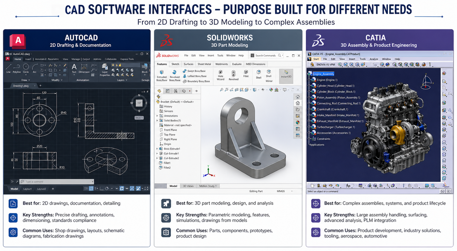
    The shift from hand-drawn drafting to Computer-Aided Design (CAD) transformed the speed and accuracy of the process, but it did not change its fundamental purpose. Today, the vast majority of engineering drawings are produced using CAD software such as AutoCAD, SolidWorks, or CATIA, but the standards, conventions, and principles that govern what a drawing must contain have remained largely consistent for decades.

    Get the difference between 2D vs 3D CAD Drafting and when to used each

    Engineering Drafting vs Engineering Design: An Important Distinction

    These two terms are often used interchangeably, but they describe distinct activities. Engineering design is the process of solving an engineering problem, deciding how something should work, what it should be made of, and what form it should take. Engineering drafting is the process of documenting that solution in a precise, communicable format.

    In practice, the same person often does both. But understanding the distinction matters when you are commissioning work: if you have a resolved design and simply need it documented for manufacturing, you need drafting. If you need someone to help figure out the design itself, you need design engineering. SimuTecra provides both, which is why understanding where your project sits on that spectrum is the starting point of any engagement.

    What Does an Engineering Drawing Actually Contain?

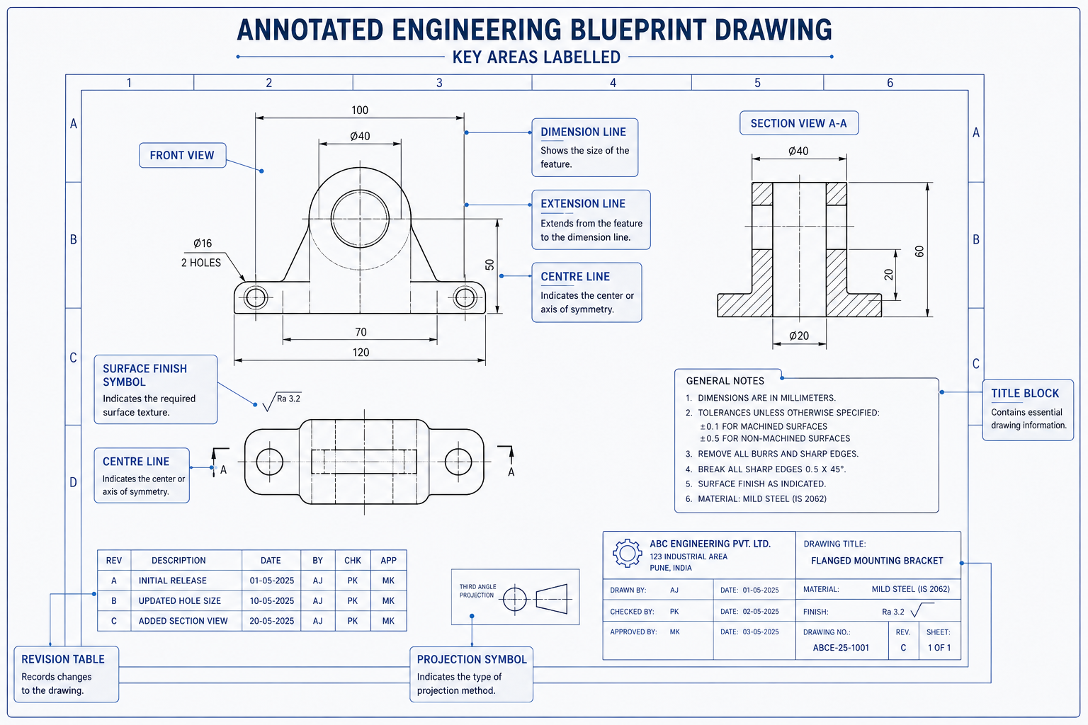
    A well-produced engineering drawing is structured, not a freeform document. Every element has a defined purpose and a defined location. Here is what you will find on a standard engineering drawing and why each element exists:

    Drawing ElementWhat It ContainsWhy It Matters
    Title BlockPart name, drawing number, scale, revision, drafter, date, company nameIdentifies the drawing and confirms you have the correct, latest revision
    Revision TableHistory of changes: revision letter, description, date, approverTracks every change made to the drawing over its lifetime
    Orthographic ViewsFront, top, side, and section views of the partCommunicates shape and geometry from multiple angles without ambiguity
    DimensionsLinear, angular, radius, and diameter measurements with unitsTells the manufacturer exactly how large every feature needs to be
    TolerancesAllowable variation on each dimension (plus/minus, limits, or GD&T)Defines how precisely each feature must be made, controls fit and function
    Material CalloutMaterial specification, grade, and sometimes heat treatment or finishTells the manufacturer what to make the part from
    Surface FinishRa values, finish symbols, or text notes on specific surfacesControls how smooth or rough a surface needs to be for its function
    Notes SectionGeneral and specific notes: standards, treatments, inspection requirementsCaptures any requirement that cannot be expressed graphically
    BOM (assemblies)List of all components: part number, description, quantity, materialProvides a complete parts list for assembly drawings

    The level of detail included on any given drawing depends on its purpose. A detail drawing for a machined part will be heavily dimensioned with tight tolerances. A general arrangement drawing for a process plant might show only positional relationships and overall sizes, with the detail left to subordinate drawings. Both are equally valid, the question is always whether the drawing contains everything the reader needs to do their job.

    A Real-World Example: The Humble Pressure Vessel Flange

    Consider a standard pressure vessel flange, a circular steel fitting used to connect pipes in industrial systems. A complete drawing package for that flange includes a detail drawing specifying the exact outer diameter, bore, flange thickness, bolt hole circle diameter, number and size of bolt holes, and surface finish on the sealing face. It will call out the material grade (say, ASTM A105), specify any heat treatment, and reference the applicable standard (ASME B16.5).

    Without that drawing, the machinist is guessing. With it, the flange can be produced to the same specification anywhere in the world, by any competent machinist, in any country, and it will fit correctly when it arrives on-site. That universality is the entire point of engineering drafting.

    The Main Types of Engineering Drawings

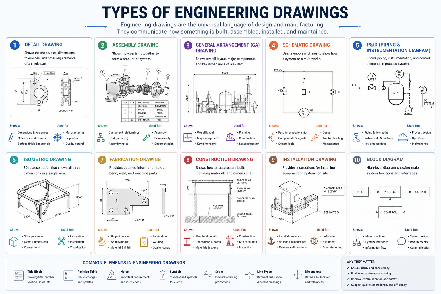
    Engineering drawings are not one-size-fits-all. Different types of drawings serve different purposes at different stages of a project. The table below covers the most common types you are likely to encounter:
    Drawing TypeWhat It ShowsCommon Use
    Detail DrawingA single component in full, all dimensions, tolerances, materialMachined parts, fabricated components
    Assembly DrawingHow multiple parts fit together; includes BOMGearboxes, structural frames, product assemblies
    GA DrawingOverall layout and spatial arrangement of a systemPlant design, facilities, building services
    Fabrication DrawingWeld symbols, bend lines, cut profiles, material for fabricated itemsSteel structures, sheet metal, pressure vessels
    Schematic DrawingSystem logic using symbols, not physical layoutElectrical, hydraulic, pneumatic systems
    As-Built DrawingWhat was actually constructed, updated after installationFacilities management, renovation, maintenance
    Shop DrawingContractor-produced drawing showing how they intend to build or fabricateConstruction, steelwork, glazing, joinery

    Most projects require more than one drawing type. A new industrial facility, for example, might require general arrangement drawings for overall layout, fabrication drawings for structural steelwork, schematics for electrical and hydraulic systems, and as-built drawings once construction is complete. Each drawing type feeds into the next stage of the project.

    Drawing Standards: Why ASME, ISO, and DIN Exist

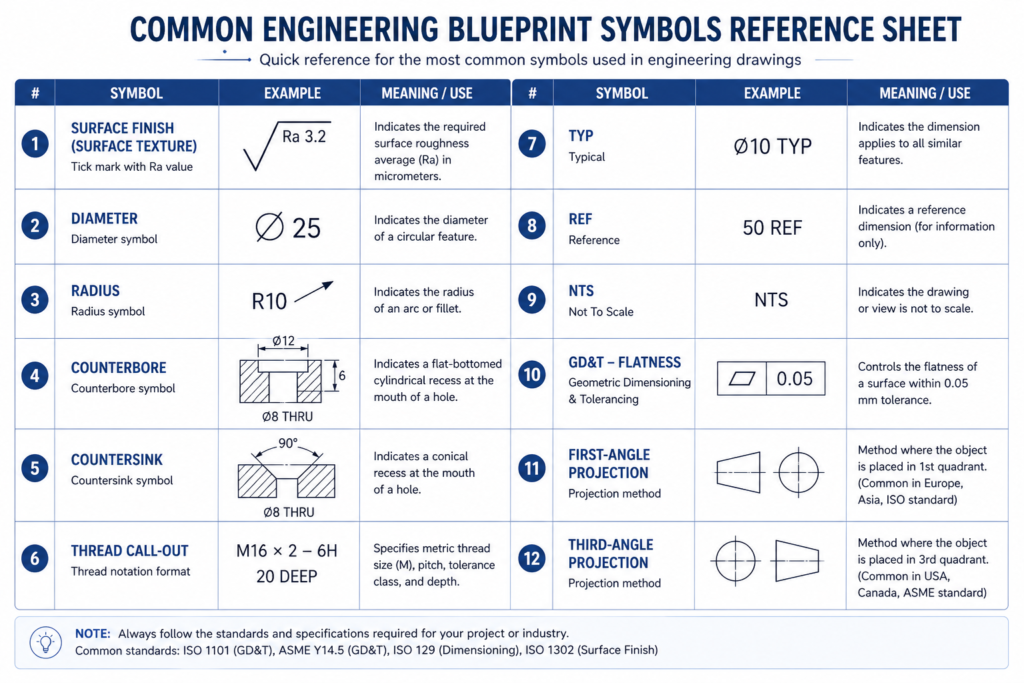
    Engineering drawings only work as a universal communication tool if everyone reading them interprets them the same way. That is the job of drawing standards, they define exactly how dimensions should be presented, what symbols mean, how tolerances are expressed, and how views should be arranged.

    Drawing Standards: Why ASME, ISO, and DIN Simutecra

    The three major standards frameworks you will encounter are:

    • ASME Y14.5 (American Society of Mechanical Engineers): The dominant standard in the United States and widely used in North America. Governs dimensioning, tolerancing, and GD&T notation. Most manufacturing and engineering firms in the US work to ASME standards unless a client specifies otherwise.
    • ISO 128 / ISO 1101 (International Organization for Standardization): The international standard used across Europe, Asia, and most of the rest of the world. Similar in intent to ASME but with some differences in projection method, GD&T notation, and symbology. When working with international suppliers or clients, knowing which standard applies is critical.
    • DIN (Deutsches Institut fur Normung): The German standard, now largely harmonised with ISO. Still referenced on drawings produced in Germany and sometimes seen in Central European manufacturing supply chains.

    When commissioning engineering drawings, always specify which standard you require. A drawing produced to ISO first-angle projection cannot be read correctly by someone trained only on ASME third-angle projection, the views appear mirrored.

    SimuTecra produces drawings to ASME, ISO, or client-specified standards. If you are not sure which applies to your project, the answer is usually determined by where the parts will be manufactured or which country the client is based in.

    What Does an Engineering Drafter Actually Do?

    The role of an engineering drafter is more than operating CAD software. A competent drafter interprets design intent from sketches, specifications, or engineer markups and translates it into precise drawings. They apply the correct dimensioning scheme, select appropriate tolerances based on fit and function requirements, add surface finish callouts, reference applicable material standards, and structure the drawing package so it can be read and used without ambiguity by the manufacturing team.

    They also manage revisions, when a design changes, the drafter updates affected drawings, increments the revision level, records the change in the revision table, and reissues the affected sheets. In a production environment, drawing control is as important as drawing quality. An outdated drawing in the hands of a machinist is a manufacturing defect waiting to happen.

    At SimuTecra, drafters work closely with engineers and clients through each revision cycle, maintaining a clear audit trail from concept through to final issued-for-construction drawings.

    Frequently Asked Questions

    QuestionAnswer
    Is engineering drafting still relevant with 3D modeling?Absolutely. 3D modeling is a powerful design tool, but a 2D drawing package remains the standard deliverable for manufacturing. Fabricators, machinists, and contractors work from 2D drawings because they define the legal specification of what is to be made. In most projects, 3D modeling and 2D drafting are used together, the model is the design environment, the drawing is the manufacturing document.
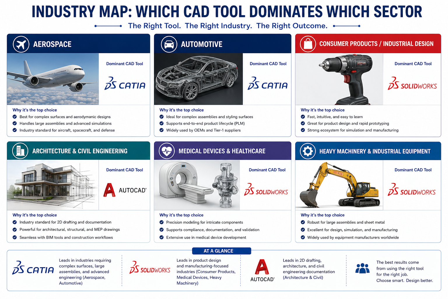
    What software do engineering drafters use?The most widely used tools are AutoCAD (2D drafting, all industries), SolidWorks (mechanical and product design), CATIA (aerospace and automotive), Autodesk Inventor (mechanical), and Revit (building and infrastructure, used alongside AutoCAD for MEP and structural work). The right tool depends on the industry and the complexity of the work.
    How long does it take to produce an engineering drawing?It depends entirely on complexity. A simple machined part detail drawing might take two to four hours. A complex assembly drawing with a full BOM could take two days. A full drawing package for a structural steel frame or a process plant module could take several weeks. The most reliable way to estimate is to share your scope with a drafting partner and request a breakdown.
    What industries use engineering drafting?Engineering drafting is used in virtually every industry that involves physical construction or manufacturing: mechanical and product engineering, civil and structural engineering, architecture, oil and gas, mining, aerospace, automotive, marine, HVAC and building services, electronics manufacturing, and more. The specific drawing types and standards vary by industry, but the underlying discipline is the same.
    What is the difference between a blueprint and an engineering drawing?Technically, ‘blueprint’ refers to an older reproduction process that produced white lines on a blue background. The term has stuck as a colloquial term for any engineering drawing, even though modern drawings are produced digitally and printed on white paper. In professional practice, ‘engineering drawing’ or ‘technical drawing’ is the correct term.

    The Bottom Line

    Engineering drafting is one of the oldest and most essential disciplines in engineering, and despite decades of technological change, its core purpose has not shifted: to communicate design intent precisely enough that anyone with the relevant skill can build the thing correctly, first time.

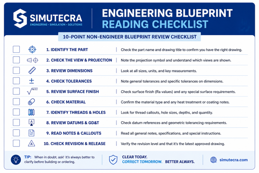
    Whether you are a project manager reviewing a drawing package, a business owner commissioning fabrication work, or an engineer looking to understand what your drafting team actually produces, the fundamentals covered in this guide give you the foundation to engage with technical drawings with confidence.

    The next step is learning how to read what is on them, which is exactly what the next article in this series covers.

    Need Engineering Drawings You Can Actually Build From?

    SimuTecra produces 2D drafting packages and 3D CAD models for manufacturing, fabrication, and construction clients worldwide. Every drawing is produced to your specified standard, ASME, ISO, or client-specific, and reviewed for accuracy before delivery.

    Send us your project details and get a clear scope and quote, no obligation.

  • Claude Prompts for Engineers: 20 Ready-to-Use Prompts for CAD, Design, and Manufacturing

    Claude Prompts for Engineers: 20 Ready-to-Use Prompts for CAD, Design, and Manufacturing

    Engineers are not short of things to do. Documentation, drawing reviews, specification writing, supplier communication, tolerance analysis, DFM checks, the work that surrounds the actual engineering is substantial, and most of it follows repeatable patterns. Claude prompts for engineers handles repeatable patterns well.

    This is a working reference guide: 20 prompts across five categories, each one built for a specific engineering task. They are written to be used directly, copy, adapt to your context, and go. The goal is to save you time on the surrounding work so you can spend it on the engineering that actually requires your expertise.

    How to Get the Most Out of These Claude Prompts for Engineers

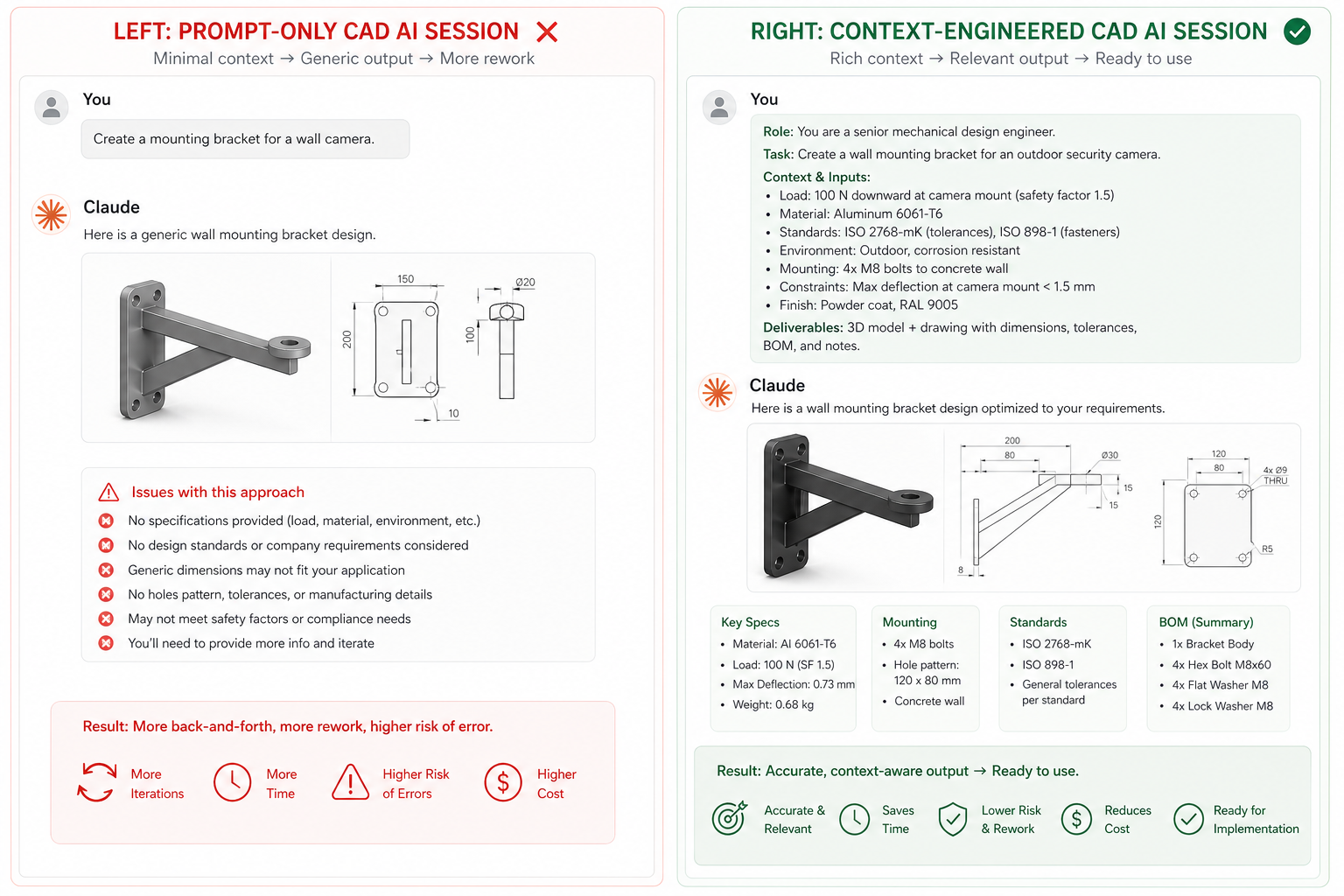
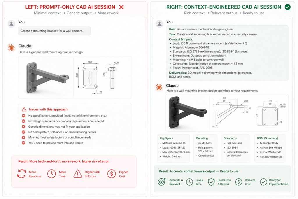
    Claude’s output quality scales directly with the context you give it. Every prompt below includes placeholder brackets, fill these with your actual project details before sending. A prompt with specifics gets a specific, usable answer. A vague prompt gets a generic one.

    A few principles that apply across all of these:

    • Tell Claude your role and context upfront. ‘I am a mechanical engineer reviewing a supplier’s drawing package for a precision machined housing’ gives Claude a framework it uses throughout the conversation.
    • Iterate. The first response is a starting point, not a final output. Push back, ask for more depth on a specific section, ask it to rewrite something in a different format.
    • Use Claude’s output as a first draft. Everything it produces, specifications, checklists, documentation, should be reviewed by a qualified engineer before it is used in production. Claude accelerates the writing; the engineering judgment is still yours.
    Claude engineering prompt categories | AI prompts CAD manufacturing | engineering AI use cases

    Category 1: Drawing Review and Documentation

    Drawing review and documentation are among the highest-value areas for Claude in an engineering context. The work is structured, the requirements are well-defined, and the output, checklists, review notes, revision summaries, is exactly the kind of writing Claude does well.

    Prompt 1: Drawing Review Checklist

    DRAWING & DOCUMENTATION
    Generate a drawing review checklist
    I am reviewing a [2D detail drawing / assembly drawing / general arrangement drawing] for a [describe the part or assembly, e.g. ‘precision machined aluminium housing for an industrial pump’]. The drawing was produced to [ASME Y14.5 / ISO 128] standards. Generate a structured review checklist covering:1. Title block completeness2. View and projection correctness3. Dimensioning completeness and correctness4. Tolerance specification (GD&T and general)5. Material and surface finish callouts6. Notes and special requirements7. Drawing standard compliance Format as a checklist I can work through during the review.

    Prompt 2: Revision Description

    DRAWING & DOCUMENTATION
    Write a drawing revision description
    I need to write a revision description for an engineering drawing. The revision number is [e.g. Rev C]. The changes made from the previous revision are:[List the changes, e.g. ‘Added 2x M6 tapped holes on the top face, increased wall thickness from 4mm to 6mm on the side flanges, updated surface finish callout from Ra 3.2 to Ra 1.6 on the bore’]Write a concise, professional revision description suitable for the drawing title block revision history table. Maximum 3 sentences.

    Prompt 3: Drawing Notes Section

    DRAWING & DOCUMENTATION
    Draft a general notes section
    I need to write the general notes section for a manufacturing drawing for a [describe the part, material, manufacturing method, any special requirements].Draft a complete general notes section covering:- Applicable drawing standard- Default tolerances for dimensions without explicit callouts- Surface finish unless otherwise specified- Material and heat treatment- Any special manufacturing or inspection requirements- Deburring and edge break requirementsUse professional engineering drawing language.

    Prompt 4: Bill of Materials

    DRAWING & DOCUMENTATION
    Structure a Bill of Materials
    I need to create a Bill of Materials for an assembly. The assembly consists of:[List each component: description, quantity, material or part number if known, e.g. ‘1x aluminium housing (custom machined), 4x M8x25 cap head screws (ISO 4762), 2x lip seals (NBR, 25mm bore)’]Format this as a structured BOM table with columns for: Item No., Description, Quantity, Part Number / Standard Reference, Material, Notes. Flag any items where I have not provided enough information.

    Category 2: Design Review and DFM

    Design for Manufacturability (DFM) reviews and design checks are time-consuming when done from scratch. Claude helps you structure the review, generate the right questions, and document findings consistently.

    Prompt 5: DFM Review

    DESIGN REVIEW & DFM
    Run a Design for Manufacturability check
    I need to conduct a DFM review on a [describe the part: geometry, material, manufacturing method, e.g. ‘injection moulded ABS housing with snap-fit clips and external ribbing’]. The part will be manufactured by [describe the process and any constraints e.g. ‘a Tier 2 injection moulding supplier, target unit cost under £3 at 10,000 units per year’].Review the following DFM considerations and flag any potential issues:1. Wall thickness uniformity2. Draft angles3. Undercuts and mould release4. Gate location and sink mark risk5. Tolerance achievability for the process6. Feature accessibility for tooling7. Part consolidation opportunitiesI will provide additional geometry details as needed.

    Prompt 6: Tolerance Stack-Up Explanation

    DESIGN REVIEW & DFM
    Explain a tolerance stack-up scenario
    I have a tolerance stack-up question. In my assembly:[Describe the assembly and the dimensional chain e.g. ‘Part A has a length of 50mm ±0.1mm. Part B has a bore depth of 52mm ±0.15mm. These parts must interface so that Part A sits 2mm below the face of Part B with a tolerance of ±0.05mm’]Please:1. Explain whether the stated tolerances are compatible with the assembly requirement2. Show the worst-case tolerance calculation3. Identify which tolerances are driving the stack and which have the most room to relax4. Suggest options if the stack does not close

    Prompt 7: Material Selection Comparison

    DESIGN REVIEW & DFM
    Compare material options for a specific application
    I am selecting a material for a [describe the part and its application e.g. ‘bracket that will be exposed to outdoor weather, moderate mechanical load from vibration, needs to be painted, manufactured by laser cutting and bending’].Please compare the following materials for this application: [list your candidate materials e.g. ‘mild steel (S275), 316 stainless steel, 6082-T6 aluminium’]Compare on: strength-to-weight, corrosion resistance, machinability/formability, relative material cost, weldability, and suitability for the manufacturing method. Recommend the best option and explain the tradeoffs.

    Prompt 8: Design Change Impact Assessment

    DESIGN REVIEW & DFM
    Assess the impact of a proposed design change
    I am considering a design change on an existing part. The current design is [describe briefly]. The proposed change is [describe the change e.g. ‘increasing the wall thickness from 3mm to 5mm on one face to improve stiffness under bending load’].Please assess the likely impact of this change on:1. Part mass2. Manufacturing cost (machining time, material use)3. Lead time4. Any adjacent features or assembly interfaces that may be affected5. Whether the change is likely to require a drawing revision or a full re-qualificationFlag any downstream effects I may not have considered.

    Category 3: Specification and Technical Writing

    Engineering specifications, inspection plans, test procedures, and technical reports follow consistent structures. Claude drafts these faster than starting from a blank page and with the right prompt, the structure it produces is close to what you would write yourself.

    Prompt 9: Incoming Inspection Plan

    SPECIFICATION WRITING
    Draft an incoming inspection plan
    I need to create an incoming inspection plan for a purchased component. The component is: [describe material, dimensions, manufacturing method, critical features].The key quality requirements are: [list e.g. ‘bolt hole position within 0.3mm, surface finish Ra 1.6 on sealing face, hardness 200-240 HB, no visible porosity on machined surfaces’].Draft an inspection plan with:- Inspection scope (100% or sample-based, with rationale)- Measurement method for each characteristic- Acceptance criteria- Non-conformance disposition instructionsFormat as a table I can use directly.

    Prompt 10: Technical Specification Document

    SPECIFICATION WRITING
    Write a part or assembly specification
    I need to write a technical specification document for [describe the part or assembly]. This specification will be used by [describe the audience supplier, internal manufacturing team, QA department].The specification must cover:[List the key requirements dimensions, material, surface treatment, functional performance requirements, applicable standards, test requirements]Structure the document with: Scope, References, Material Requirements, Dimensional Requirements, Surface and Finish Requirements, Functional Requirements, Inspection and Test Requirements, Packaging and Marking.Write in formal technical language appropriate for a supplier-facing document.

    Prompt 11: Engineering Change Notice

    SPECIFICATION WRITING
    Draft an Engineering Change Notice (ECN)
    I need to draft an Engineering Change Notice for the following change:- Part / Assembly affected: [name and number]- Drawing revision: from [Rev X] to [Rev Y]- Description of change: [describe what changed and why]- Reason for change: [technical issue, cost reduction, supplier change, customer requirement, etc.]- Effectivity: [when the change takes effect e.g. ‘from serial number 1247’, ‘from batch date 01/06/2025’, ‘immediate’]- Impact on existing stock / WIP: [describe]Draft a complete ECN document in a format suitable for internal engineering records and supplier notification.
    Claude AI engineering documentation | AI specification writing engineer | Claude prompts technical writing

    Category 4: Supplier and Procurement Communication

    Supplier communication eats engineering time. RFQ preparation, technical queries, non-conformance documentation, and supplier evaluation all involve structured writing that follows established patterns. These prompts handle the structure so you can focus on the content.

    Prompt 12: RFQ Technical Package

    SUPPLIER & PROCUREMENT
    Draft the technical section of an RFQ
    I am preparing a Request for Quotation for the manufacture of [describe the part quantity, material, manufacturing method, key specifications].Draft the technical requirements section of the RFQ, covering:1. Part description and function2. Material specification and certification requirements3. Manufacturing process requirements4. Quality and inspection requirements5. Drawing and document requirements (what the supplier must confirm they have reviewed)6. Packaging and delivery requirements7. Supplier qualification requirementsWrite in formal, supplier-facing language.

    Prompt 13: Non-Conformance Report

    SUPPLIER & PROCUREMENT
    Draft a supplier non-conformance report
    I need to raise a non-conformance report against a supplier. The details are:- Supplier name: [name]- Part: [part name and number]- Batch / delivery reference: [reference]- Nature of non-conformance: [describe what is wrong e.g. ‘bore diameter measured at 24.85mm against a drawing requirement of 25.00 +0.00/-0.05mm on 6 of 20 parts inspected’]- Discovery point: [incoming inspection / during assembly / in field]- Disposition of affected parts: [return to supplier / scrap / use as-is with deviation / rework]Draft a formal NCR document requesting a corrective action response within [timeframe].

    Prompt 14: Supplier Technical Query Response

    SUPPLIER & PROCUREMENT
    Draft a response to a supplier technical query
    A supplier has raised the following technical query on our drawing: [paste or describe the supplier’s query exactly].The correct technical answer is: [describe what the answer is even if you are not sure how to phrase it formally].Draft a formal written response to the supplier that:1. Acknowledges their query clearly2. Provides the technical clarification3. Confirms whether a drawing revision is required or whether this is a clarification only4. States any action required from the supplier before proceeding

    Category 5: Technical Communication and Reporting

    Engineering findings, project updates, and technical reports are often written under time pressure and read by audiences with varying levels of technical background. These prompts help you communicate findings clearly without spending hours on the writing.

    Prompt 15: Engineering Summary for a Non-Technical Audience

    TECHNICAL COMMUNICATION
    Translate engineering findings for a non-technical audience
    I need to explain the following engineering finding to a non-technical audience [e.g. senior management, a client, a procurement team]:[Describe the finding in technical terms e.g. ‘FEA results show that the current bracket design experiences peak von Mises stress of 287 MPa at the fillet radius under the specified 5kN load, exceeding the yield strength of 6082-T6 aluminium at 260 MPa by 10%’]Rewrite this finding in plain language that:1. Explains what was found2. Explains why it matters (what will happen if unaddressed)3. States what the recommended action is4. Avoids engineering jargon without losing technical accuracy

    Prompt 16: Lessons Learned Document

    TECHNICAL COMMUNICATION
    Document project lessons learned
    I need to document lessons learned from a recently completed engineering project. The project was [brief description]. Key issues that arose were:[List the issues e.g. ‘tolerance stack-up not identified until assembly stage, causing rework on 30% of first-article parts; supplier changed material grade without notification; drawing revision control not enforced, resulting in manufacturer working from an outdated revision’]For each lesson, structure the entry as:- What happened- Root cause- Impact- Corrective action taken- Process change for future projectsWrite in a format suitable for an internal engineering knowledge base.

    Prompt 17: Design Review Meeting Agenda

    TECHNICAL COMMUNICATION
    Draft a design review meeting agenda
    I am running a [Preliminary Design Review / Critical Design Review / Drawing Review] for [describe the project or product]. The review will be attended by [list attendees and their roles e.g. ‘lead mechanical engineer, manufacturing engineer, QA manager, project manager, supplier representative’].Key topics to cover include: [list the main items e.g. ‘design concept confirmation, material selection rationale, tolerance review, supplier capability assessment, outstanding design actions, timeline to first article’]Draft a structured agenda with time allocations, objectives for each agenda item, and a list of pre-read documents attendees should review before the meeting.

    Prompt 18: Root Cause Analysis Framework

    TECHNICAL COMMUNICATION
    Structure a root cause analysis
    I need to conduct a root cause analysis for the following problem: [describe the problem clearly, what happened, when, on what product or process, and what the impact was].Please structure a 5-Why analysis for this problem, starting from the observable symptom and working back to the root cause. For each ‘Why’, provide the most likely answer based on the information I have given you, and flag where I need to gather additional data before the analysis can proceed with confidence.At the end, suggest a corrective action targeted at the root cause rather than the symptom.

    Prompt 19: Progress Report to Client

    TECHNICAL COMMUNICATION
    Write a project progress report
    I need to write a progress report for a client on an engineering project. The project is [brief description]. This report covers [time period].Progress this period:[List what has been completed]Current status:[Describe where the project stands on schedule / delayed / ahead]Issues and risks:[List any issues or risks and what is being done about them]Next steps:[List what will be completed in the next period]Write a concise, professional progress report suitable for sending directly to the client. Positive but honest in tone. No jargon.

    Prompt 20: Technical Handover Document

    TECHNICAL COMMUNICATION
    Draft a design handover document
    I need to document a design handover for [describe the project part, assembly, or system being handed over]. The handover is from [design team / CAD engineer / project engineer] to [manufacturing team / new engineer / client / supplier].The document should cover:1. Design overview and intent2. Key design decisions and their rationale3. Known constraints and limitations4. Critical features and why they are critical5. Outstanding actions or unresolved issues6. Document register (drawings, specifications, analysis reports)7. Contact information for technical queriesWrite in a format that a new team member with engineering background but no prior knowledge of this project can follow.

    The Bottom Line

    These 20 prompts cover the recurring writing and documentation tasks that surround engineering work the ones that take time without requiring the engineering judgment that is actually your competitive advantage. Claude handles the structure; you supply the context and the technical calls.

    The best way to use this guide is not to work through it sequentially, but to bookmark it and come back to the relevant section when the task arises. The prompts will save you time most consistently when you use them as starting points for an ongoing conversation rather than one-shot generators iterate, push back, and ask Claude to refine until the output is exactly what you need.

    When Claude Helps You Think, SimuTecra Handles the Execution

    Claude helps you think through problems, structure requirements, and make better decisions. SimuTecra’s engineering team handles the CAD drafting, 3D modeling, and structural analysis that turns those decisions into production-ready deliverables. Use the prompts in this guide to develop your brief then send it to us.Tell us what you are building and we will take it from there.

  • 2D vs 3D CAD Drafting: What’s the Difference and When to Use Each

    2D vs 3D CAD Drafting: What’s the Difference and When to Use Each

    2D vs 3D CAD drafting! A supplier just asked you to send over ‘the CAD files’ and you’re not sure whether to hand them a 2D drawing package or a full 3D model. Get it wrong and you’re looking at delays, rework, and a bill for work you didn’t need.

    This is one of the most common points of confusion in engineering projects, especially for teams that work with outsourced design partners or are newer to commissioning technical drawings. The truth is that 2D and 3D CAD are not competing approaches, they solve different problems at different stages of a project. Knowing which one you need, and when, saves time and money.

    This guide breaks down the practical differences between 2D CAD drafting and 3D CAD modeling, explains the strengths of each, and gives you a clear framework for choosing the right approach on your next project.

    What Is 2D CAD Drafting?

    2D CAD drafting is the process of creating flat, precise technical drawings that communicate the geometry, dimensions, tolerances, and specifications of a part, structure, or system. Rather than showing an object as it looks in the real world, a 2D drawing presents multiple standardised views, typically a front view, a top view, and one or more side views, using a technique called orthographic projection.

    Think of it as a highly structured set of instructions. A machinist reading a 2D drawing knows the exact diameter of every hole, the tolerance on every dimension, the surface finish required on a mating face, and the material the part should be made from. Everything is defined, nothing is left to interpretation.

    2D CAD Drafting by Simutecra

    The dominant tool for 2D drafting is AutoCAD, developed by Autodesk and widely used across architecture, civil engineering, and manufacturing. Other commonly used platforms include DraftSight and BricsCAD. Drawings are typically delivered as DWG or DXF files, or as locked PDFs for review and approval.

    What a 2D Drawing Includes

    • Multiple orthographic views of the part (front, top, side, section views)
    • Fully annotated dimensions and tolerances
    • Material specification and surface finish callouts
    • GD&T symbols where geometric controls are required
    • A title block with part number, revision level, scale, and drafter information
    • A bill of materials (BOM) for assembly drawings

    2D drawings remain the universal language of manufacturing. Even when a 3D model is used during the design phase, a 2D drawing package is almost always required before a part goes into production, because it defines the legal and contractual specification of what is to be made.

    What Is 3D CAD Modeling?

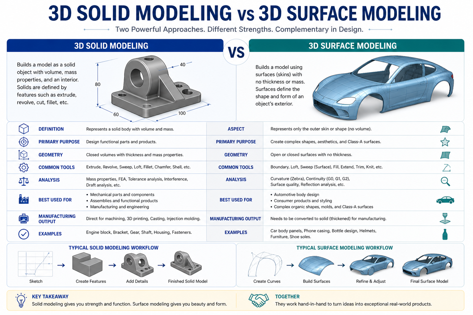
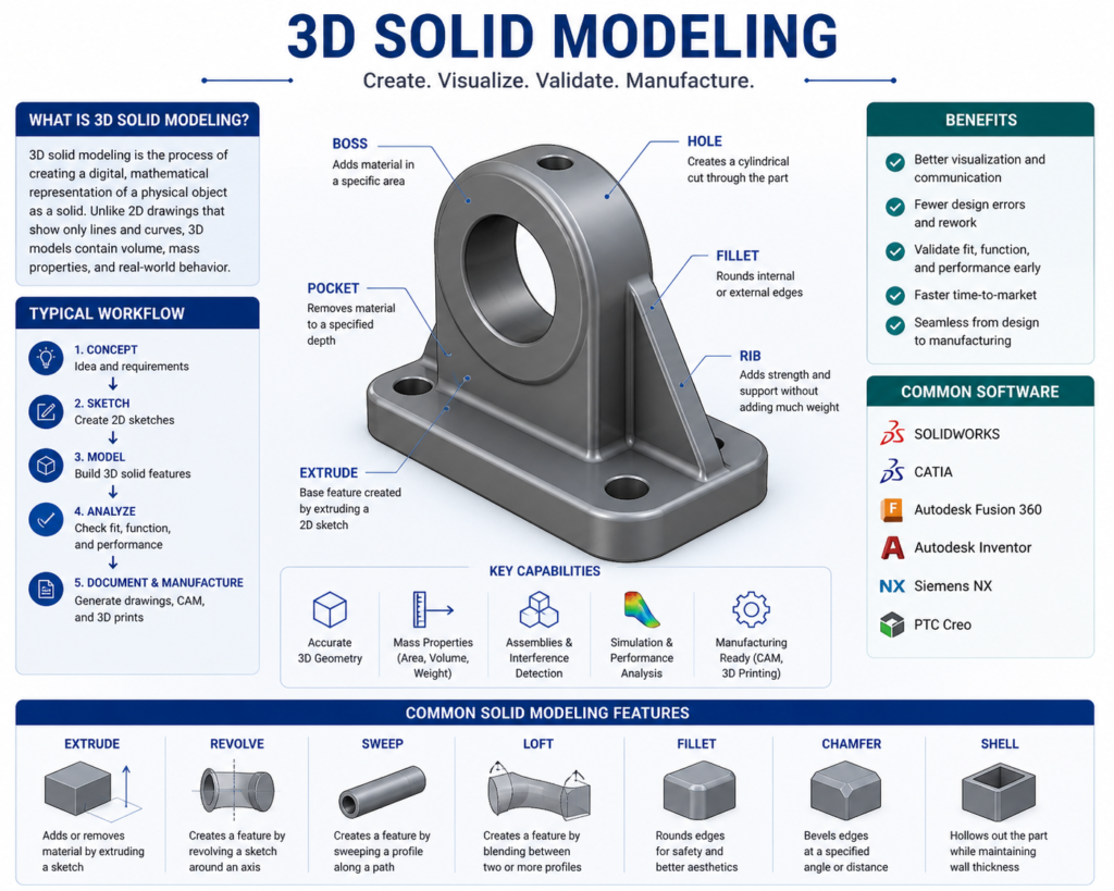
    3D CAD modeling creates a digital solid or surface representation of a part or assembly in three dimensions. Rather than describing a shape through projected views, a 3D model IS the shape, a virtual object that can be rotated, measured, assembled with other parts, and analysed for stress, heat, or fluid flow.

    Most professional 3D CAD tools are parametric, which means every feature of the model is driven by dimensions and relationships rather than fixed geometry. Change the diameter of a shaft in SolidWorks, and every downstream feature, the shoulder, the thread, the associated drawings, updates automatically. This makes 3D modeling particularly powerful during the design and development phase, where changes are frequent.

    3D CAD Modeling by Simutecra

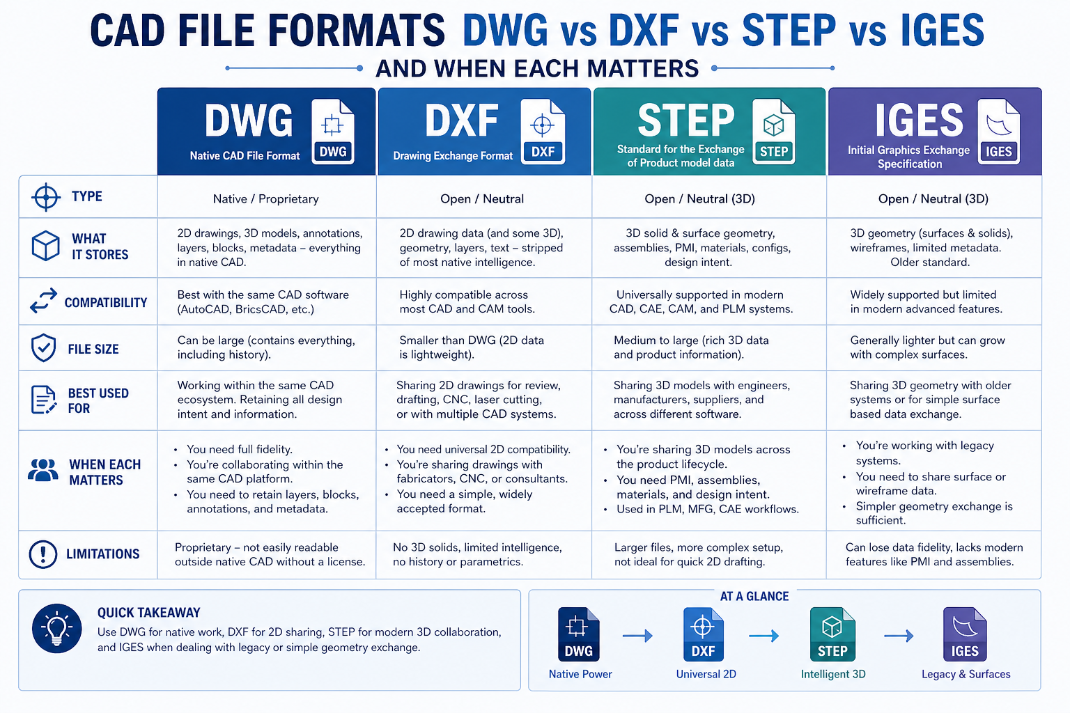
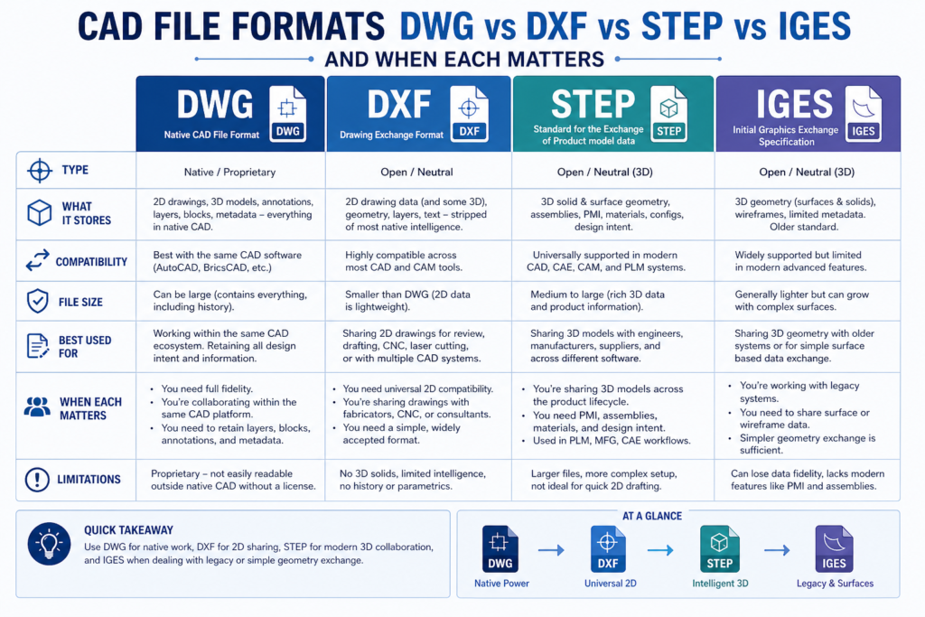
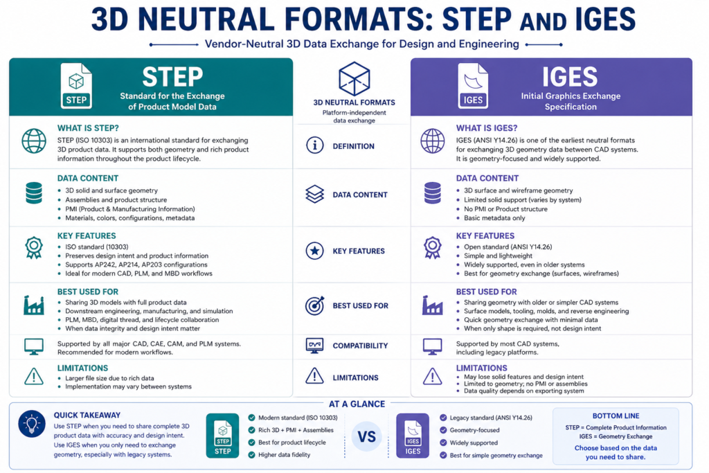
    The most widely used 3D CAD platforms include SolidWorks and Autodesk Inventor for mechanical and product design, CATIA for aerospace and automotive applications, and Fusion 360 for smaller teams and startups. Files are typically shared in STEP or IGES format for interoperability, or in native formats such as .sldprt (SolidWorks) and .ipt (Inventor) when working within the same software environment.

    What a 3D Model Enables

    • Full visualisation and rotation before anything is physically made
    • Automatic generation of 2D drawings from the 3D geometry
    • Assembly modeling, checking how parts fit together and detecting clashes
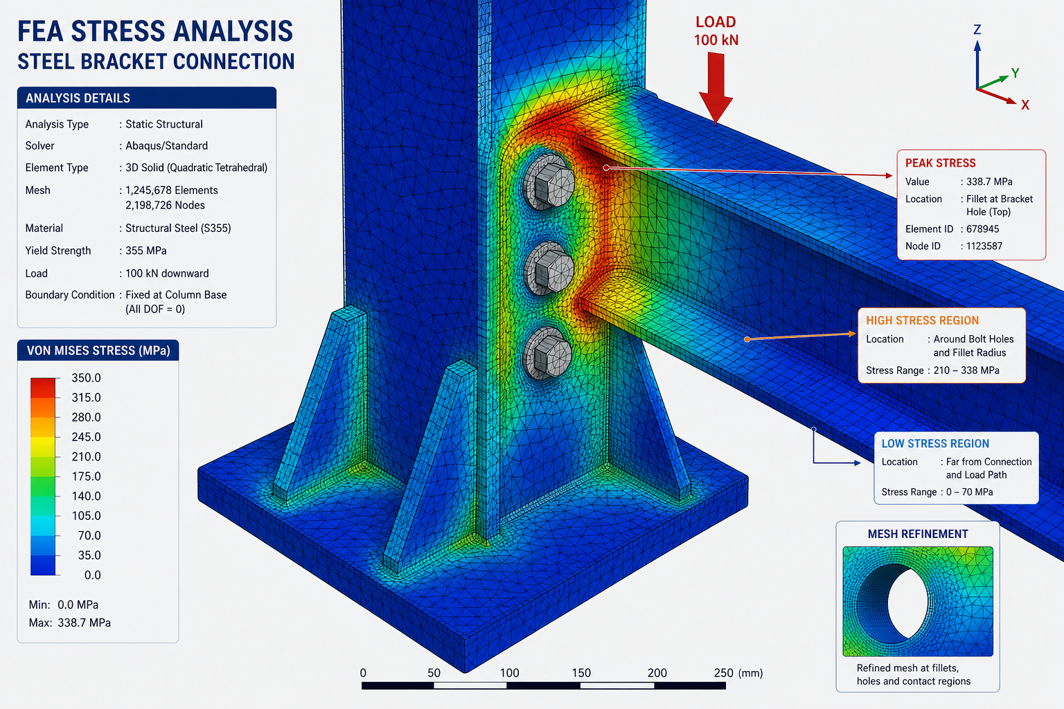
    • Finite Element Analysis (FEA) for structural stress and deflection testing
    • Computational Fluid Dynamics (CFD) for airflow and thermal analysis
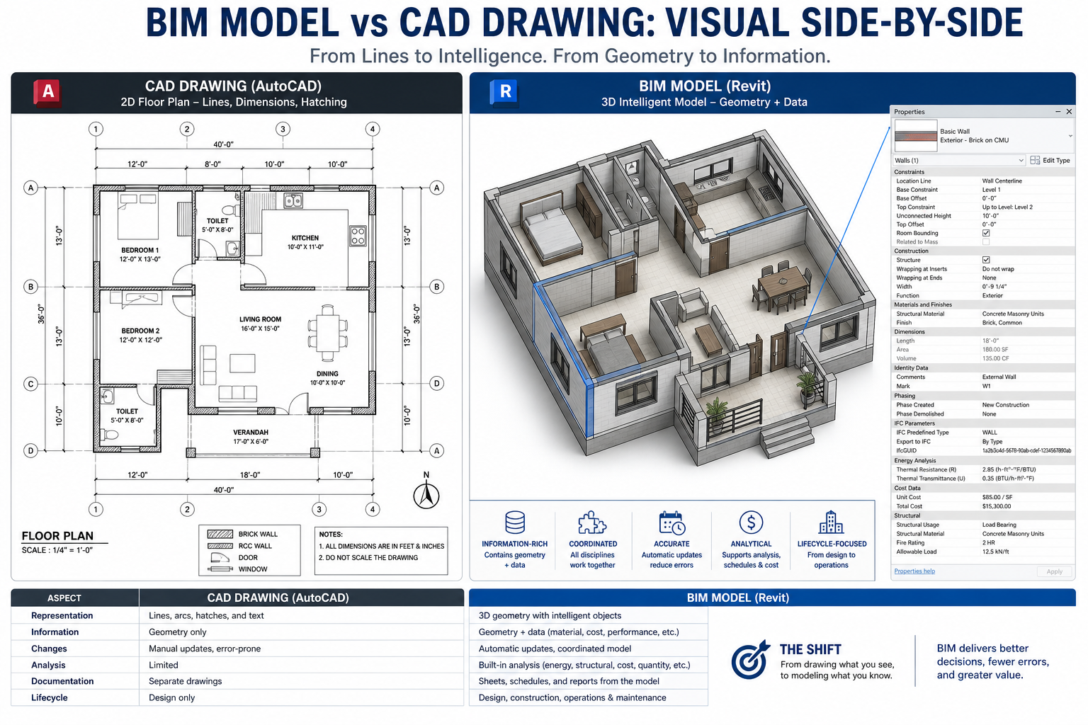
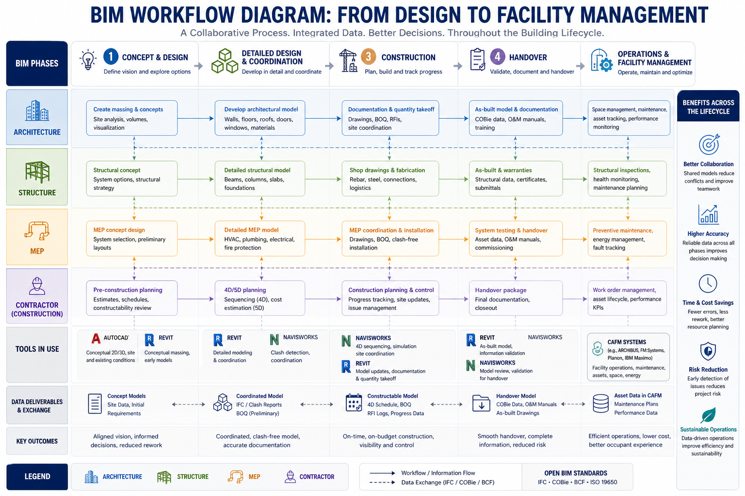
    • Integration with BIM platforms for coordination on construction projects
    • Direct export to 3D printing (STL format) or CNC toolpath generation

    3D modeling shifts a significant amount of problem-solving earlier in the process. Issues that would previously surface on the shop floor, two pipes clashing inside a wall, a bracket that doesn’t have enough clearance for a fastener, are caught on-screen instead. That upstream investment typically pays for itself.

    2D vs 3D CAD Drafting: Key Differences at a Glance

    The table below summarises the most practically relevant differences between the two approaches. Keep this as a reference when briefing your design team or outsourcing partner on what deliverables you need.

    Feature2D CAD Drafting3D CAD Modeling
    OutputFlat technical drawings (orthographic views)Digital solid/surface model + auto-generated drawings
    DimensionalityLength and width (X, Y axes)Length, width, and depth (X, Y, Z axes)
    Primary toolsAutoCAD, DraftSight, BricsCADSolidWorks, Fusion 360, CATIA, Inventor
    File outputsDWG, DXF, PDFSTEP, IGES, native formats (.sldprt, .ipt)
    Best forShop drawings, permits, simple part fabricationNew product development, assemblies, FEA, visualisation
    ComplexityFaster for straightforward geometryBetter for complex, interdependent parts
    Cost to produceLower, fewer hours for standard partsHigher upfront; saves time in revisions and prototyping
    EditabilityManual updates to each viewChange one parameter; all views update automatically

    Important: these two approaches are not mutually exclusive. In most professional engineering workflows, a project begins in 3D and ends with 2D. The 3D model is the design tool; the 2D drawing package is the manufacturing deliverable.

    A Real-World Example: Designing a Custom Mounting Bracket

    A structural fabrication company needs to design a custom steel bracket for mounting industrial HVAC units to a rooftop frame. Here is how both approaches play out on the same project:

    Using 2D drafting only: The drafter produces a set of orthographic drawings showing the bracket geometry, hole positions, weld locations, and material callout (e.g. 50x50x5 RHS, Grade 350 steel). The fabricator quotes and builds directly from those drawings. This works perfectly well, the bracket is straightforward, the geometry is easy to convey in flat views, and the drawings take half a day to produce.

    Using 3D modeling first: For a complex variant of the same job, say, a bespoke bracket that interfaces with three different beam profiles and needs to accommodate variable HVAC unit sizes the engineer builds a parametric 3D model first. The model allows the team to test fit across all configurations before committing, check that nothing clashes with the rooftop drainage, and automatically generate the 2D drawings for each bracket variant. What would have taken multiple drawing revisions is resolved in the model.

    The simple bracket warrants 2D. The complex multi-variant bracket warrants 3D. Same industry, same client, different choice, made based on geometry complexity and the cost of getting it wrong.

    When to Use 2D Drafting vs 3D Modeling: A Practical Decision Guide

    Choose 2D CAD Drafting When:

    • The geometry is straightforward. Parts with simple, well-understood shapes, flat plates, standard brackets, sheet metal panels, are faster and cheaper to document in 2D.
    • You are producing fabrication or shop drawings. The end deliverable for a fabricator, welder, or machinist is almost always a 2D drawing package. Even if you modelled in 3D, you will produce 2D drawings for manufacturing.
    • You need construction or permit drawings. Architectural and civil permit submissions, site plans, structural general arrangement drawings, and MEP coordination drawings are typically 2D.
    • You are updating legacy documentation. Existing drawing sets from older projects are in 2D. If you are revising rather than redesigning, maintaining the existing format is more efficient.
    • Speed and cost are the priority. For a single, clearly defined part with no complex interfaces, 2D is quicker to produce and cheaper to commission.

    Choose 3D CAD Modeling When:

    • You are developing a new product or assembly. When the design intent is not yet fully resolved, 3D lets you explore, test, and iterate far more efficiently than redrawing views manually.
    • Multiple parts need to fit together. 3D assembly modeling allows you to check every interface before anything is made. Clash detection on-screen is dramatically cheaper than discovering a fit problem after fabrication.
    • You need to run simulation or analysis. FEA for structural loads, CFD for airflow, thermal analysis all of these require a 3D model. You cannot run meaningful simulation on a 2D drawing.
    • Your client needs to visualise the design. 3D renders and walkthroughs are far more effective communication tools than orthographic views for non-technical stakeholders, clients, and approval bodies.
    • The design will change. Parametric 3D models update automatically when dimensions change. If you anticipate multiple iterations, the upfront investment in a 3D model pays back quickly in time saved on revisions.

    Can You Use Both on the Same Project?

    Absolutely, and in most professional engineering environments, that is exactly what happens. The 3D model is produced first as the design tool. Once the design is locked, 2D drawings are generated directly from the model, complete with dimensions, tolerances, and annotations. The 2D drawing becomes the manufacturing and contractual document; the 3D model is the source of truth for geometry.

    This workflow eliminates a significant source of error: the mismatch between a manually drawn 2D document and the actual intended 3D geometry. When drawings are derived from a 3D model, they are always geometrically consistent.

    Frequently Asked Questions

    QuestionAnswer
    Is 3D CAD always better than 2D?Not at all. 3D is more powerful for complex design work, but 2D is faster and more cost-effective for simple parts, standard fabrication drawings, and permit submissions. The right choice depends entirely on the project requirements.
    Can a 3D model replace a 2D drawing for manufacturing?In some advanced manufacturing environments using Model-Based Definition (MBD), yes, all specifications are embedded directly in the 3D model. But the vast majority of fabricators, machinists, and contractors still work from 2D drawings. Until MBD is universally adopted, a 2D drawing package remains the standard manufacturing deliverable.
    What software produces both 2D drawings and 3D models?Most professional CAD platforms do both. SolidWorks, Inventor, CATIA, and Fusion 360 all allow you to create a 3D model and then generate fully annotated 2D drawings from it within the same environment. AutoCAD has 3D capabilities but is primarily used for 2D drafting.
    How do I know which format to request from my CAD provider?For manufacturing: request a 2D drawing package (PDF + DWG/DXF). For design review or simulation: request a 3D model in STEP format, which is readable by all major CAD platforms. For 3D printing: request an STL file. When in doubt, ask your provider, a good engineering partner will recommend the right format for your workflow.

    The Bottom Line

    2D and 3D CAD are not rivals, they are tools designed for different jobs. 2D drafting is the language of manufacturing: precise, standardised, and universally understood on the shop floor. 3D modeling is the language of design: powerful for exploring complex geometry, catching fit issues early, and communicating ideas to stakeholders.

    Most engineering projects benefit from both. The key is knowing at which stage to use each, and working with a drafting partner who can deliver the right format for where your project actually is.

  • From Concept to Reality: The Complete Product Design Workflow

    From Concept to Reality: The Complete Product Design Workflow

    Introduction: The Journey from Idea to Market

    Product design is a complex journey that requires careful planning, iterative refinement, and seamless collaboration between multiple disciplines. Our comprehensive workflow ensures that every project moves efficiently from initial concept to market-ready product while maintaining the highest standards of quality, functionality, and manufacturability.

    In this detailed guide, we’ll walk you through our proven seven-phase methodology that has helped hundreds of clients successfully bring innovative products to market. Whether you’re developing a simple consumer product or a complex industrial system, this framework provides the structure and discipline needed for successful product development.

    Phase 1: Discovery and Requirements Definition

    Every successful product begins with a thorough understanding of the problem it’s designed to solve and the context in which it will operate. The discovery phase establishes the foundation for all subsequent design decisions.

    Market Research and User Analysis

    Understanding your target market and users is crucial for developing products that will succeed in the marketplace.

    Key Research Activities:

    • User Interviews: Direct conversations with potential users to understand needs, frustrations, and workflows
    • Competitive Analysis: Evaluation of existing solutions, their strengths, weaknesses, and market positioning
    • Market Sizing: Assessment of market opportunity and potential customer segments
    • Technology Trends: Understanding of relevant technological developments and future directions
    • Regulatory Landscape: Identification of applicable standards, certifications, and compliance requirements

    Requirements Gathering and Prioritization

    Clear, well-prioritized requirements are essential for focused design efforts and successful project outcomes.

    Requirement Categories:

    • Functional Requirements: What the product must do
    • Performance Requirements: How well it must perform
    • Design Constraints: Limitations on size, weight, cost, materials, etc.
    • User Experience Requirements: Ease of use, accessibility, and aesthetic considerations
    • Manufacturing Requirements: Production volume, cost targets, and manufacturing constraints
    • Compliance Requirements: Safety, environmental, and regulatory standards

    Stakeholder Alignment

    Ensuring all stakeholders share a common understanding of project goals and constraints prevents costly misalignments later in the process.

    Stakeholder Alignment Activities:

    • Requirements review and sign-off
    • Success criteria definition
    • Risk assessment and mitigation planning
    • Resource and timeline planning
    • Communication protocols establishment

    Phase 2: Concept Development and Ideation

    With a solid understanding of requirements and constraints, the concept development phase focuses on generating and evaluating potential solutions.

    Ideation Techniques

    Effective ideation requires structured approaches that encourage creative thinking while maintaining focus on user needs and technical feasibility.

    Proven Ideation Methods:

    • Brainstorming Sessions: Structured group creativity sessions with diverse perspectives
    • Mind Mapping: Visual exploration of concept relationships and dependencies
    • SCAMPER Technique: Systematic approach to modifying and improving existing solutions
    • Biomimicry: Learning from natural systems and processes
    • Cross-Industry Analysis: Adapting solutions from other industries and applications

    Concept Evaluation and Selection

    Systematic evaluation ensures that the most promising concepts advance to detailed development.

    Evaluation Criteria:

    • Technical Feasibility: Can it be built with available technology and resources?
    • Market Viability: Will customers want it and pay for it?
    • Manufacturing Feasibility: Can it be produced at target cost and volume?
    • Competitive Advantage: Does it offer meaningful differentiation?
    • Risk Assessment: What are the technical, market, and business risks?
    • Resource Requirements: Development time, cost, and expertise needed

    Concept Visualization

    Clear visualization helps stakeholders understand and evaluate concepts effectively.

    Visualization Tools:

    • Sketches and renderings
    • Concept models and mockups
    • Storyboards and use case scenarios
    • Technical architecture diagrams
    • Functional block diagrams

    Phase 3: Detailed Design and Engineering

    The detailed design phase transforms selected concepts into fully specified products ready for manufacturing.

    Design for Manufacturing (DFM)

    Incorporating manufacturing considerations early in the design process prevents costly redesigns and ensures producibility.

    DFM Principles:

    • Material Selection: Choosing materials that balance performance, cost, and manufacturability
    • Process Optimization: Designing parts for efficient manufacturing processes
    • Tolerance Analysis: Ensuring parts fit and function properly when manufactured
    • Assembly Design: Simplifying assembly processes and reducing labor costs
    • Quality Considerations: Designing features that facilitate inspection and quality control

    3D Modeling and Documentation

    Precise 3D models and comprehensive documentation ensure accurate communication of design intent.

    Modeling Best Practices:

    • Parametric modeling for design flexibility
    • Feature-based modeling for design intent capture
    • Assembly modeling for fit and function verification
    • Configuration management for design variants
    • Standard modeling practices for team consistency

    Documentation Requirements:

    • Detailed drawings with dimensions and tolerances
    • Material specifications and finish requirements
    • Assembly instructions and procedures
    • Quality requirements and inspection criteria
    • Packaging and shipping specifications

    Engineering Analysis and Validation

    Comprehensive analysis ensures that designs meet all performance requirements before physical testing.

    Analysis Types:

    • Structural Analysis: Stress, deflection, and failure prediction
    • Thermal Analysis: Heat transfer and temperature distribution
    • Fluid Analysis: Flow patterns and pressure distributions
    • Modal Analysis: Vibration characteristics and resonance avoidance
    • Fatigue Analysis: Long-term durability under cyclic loading

    Phase 4: Prototyping and Testing

    Prototyping validates design concepts, verifies performance, and identifies issues that require resolution before production.

    Prototyping Strategy

    Effective prototyping requires a strategic approach that balances cost, time, and validation objectives.

    Prototype Types:

    • Concept Prototypes: Early models to verify basic functionality and user interaction
    • Form Prototypes: Appearance models for aesthetic evaluation and user feedback
    • Functional Prototypes: Working models that demonstrate key features and performance
    • Production Prototypes: Parts made using production processes and materials
    • Pilot Production: Small-scale production runs to validate manufacturing processes

    Rapid Prototyping Technologies

    Modern prototyping technologies enable faster iteration and more comprehensive testing.

    Prototyping Methods:

    • 3D Printing: Fast, flexible prototyping for complex geometries
    • CNC Machining: High-precision prototypes in production materials
    • Injection Molding: Low-volume tooling for production-like parts
    • Sheet Metal Fabrication: Rapid prototyping of metal components
    • Electronic Prototyping: Breadboarding and PCB prototyping for electronic systems

    Testing and Validation

    Comprehensive testing ensures that products meet all requirements and perform reliably in real-world conditions.

    Testing Categories:

    • Functional Testing: Verification that all features work as intended
    • Performance Testing: Measurement of key performance parameters
    • Environmental Testing: Performance under various environmental conditions
    • Durability Testing: Long-term reliability and wear characteristics
    • Safety Testing: Compliance with relevant safety standards
    • User Testing: Real-world usability and user experience validation

    Phase 5: Design Optimization and Refinement

    Based on testing results and stakeholder feedback, designs are refined and optimized for final production.

    Performance Optimization

    Systematic optimization ensures that products achieve the best possible performance within cost and manufacturing constraints.

    Optimization Approaches:

    • Parametric Optimization: Fine-tuning design parameters for optimal performance
    • Material Optimization: Selecting the best materials for each application
    • Geometric Optimization: Refining shapes and features for improved function
    • Weight Optimization: Minimizing weight while maintaining performance
    • Cost Optimization: Reducing costs through design and process improvements

    Design for Assembly (DFA)

    Optimizing assembly processes reduces manufacturing costs and improves product quality.

    DFA Principles:

    • Minimize the number of parts and fasteners
    • Design for single-direction assembly
    • Eliminate or simplify adjustments
    • Use self-aligning and self-locating features
    • Design for automated assembly when appropriate

    Quality and Reliability Engineering

    Building quality and reliability into the design prevents field failures and reduces warranty costs.

    Quality Engineering Techniques:

    • Failure Mode and Effects Analysis (FMEA): Systematic identification of potential failures
    • Design of Experiments (DOE): Optimization of multiple design variables simultaneously
    • Statistical Tolerance Analysis: Ensuring robust performance despite manufacturing variations
    • Reliability Prediction: Estimating product life and maintenance requirements
    • Design Reviews: Cross-functional evaluation of design quality and completeness

    Phase 6: Production Planning and Implementation

    Successful product launch requires careful planning and coordination of manufacturing, supply chain, and quality systems.

    Manufacturing Process Development

    Developing robust manufacturing processes ensures consistent quality and efficient production.

    Process Development Activities:

    • Process Selection: Choosing optimal manufacturing processes for each component
    • Tooling Design: Developing jigs, fixtures, and production tooling
    • Process Optimization: Fine-tuning processes for quality and efficiency
    • Quality Planning: Developing inspection and quality control procedures
    • Operator Training: Ensuring production teams understand processes and requirements

    Supply Chain Development

    Reliable supply chains are essential for successful product launches and ongoing production.

    Supply Chain Considerations:

    • Supplier Selection: Evaluating and qualifying component suppliers
    • Supply Chain Risk Management: Identifying and mitigating supply chain risks
    • Inventory Management: Balancing inventory costs with production flexibility
    • Logistics Planning: Optimizing transportation and distribution
    • Supplier Relationships: Building long-term partnerships for continuous improvement

    Quality Systems Implementation

    Robust quality systems ensure that products consistently meet specifications and customer expectations.

    Quality System Elements:

    • Quality planning and control procedures
    • Inspection and testing protocols
    • Statistical process control systems
    • Nonconforming material procedures
    • Continuous improvement processes

    Phase 7: Launch and Post-Launch Support

    Product launch is just the beginning of the product lifecycle. Ongoing support ensures customer satisfaction and provides insights for future improvements.

    Product Launch Planning

    Successful launches require coordination across multiple functions and careful attention to customer needs.

    Launch Activities:

    • Production Ramp-up: Gradually increasing production to full capacity
    • Quality Monitoring: Intensive quality oversight during early production
    • Customer Training: Ensuring customers can use products effectively
    • Technical Support: Providing responsive support for customer questions and issues
    • Marketing Support: Developing technical marketing materials and support

    Post-Launch Monitoring and Improvement

    Continuous monitoring and improvement ensure long-term product success and customer satisfaction.

    Post-Launch Activities:

    • Performance Monitoring: Tracking key performance indicators and customer feedback
    • Quality Tracking: Monitoring field performance and warranty claims
    • Cost Optimization: Ongoing efforts to reduce costs and improve margins
    • Product Updates: Implementing improvements and addressing issues
    • Next Generation Planning: Using insights to inform future product development

    Knowledge Capture and Transfer

    Capturing and sharing lessons learned improves future projects and builds organizational capabilities.

    Knowledge Management:

    • Project retrospectives and lessons learned documentation
    • Best practices capture and sharing
    • Design guideline development and updates
    • Team knowledge transfer and training
    • Organizational capability building

    Best Practices for Successful Product Development

    Cross-Functional Collaboration

    Successful product development requires seamless collaboration between engineering, manufacturing, marketing, and other functions.

    Collaboration Strategies:

    • Regular cross-functional design reviews
    • Co-located teams when possible
    • Shared project management tools and systems
    • Clear communication protocols and expectations
    • Conflict resolution procedures

    Risk Management

    Proactive risk management prevents surprises and keeps projects on track.

    Risk Management Approach:

    • Early risk identification and assessment
    • Risk mitigation planning and implementation
    • Regular risk review and updates
    • Contingency planning for critical risks
    • Risk communication and escalation procedures

    Customer Focus

    Maintaining focus on customer needs throughout the development process ensures market success.

    Customer Focus Techniques:

    • Regular customer feedback collection and analysis
    • User testing at multiple development stages
    • Customer advisory panels and beta programs
    • Voice of customer integration in design decisions
    • Customer satisfaction tracking and improvement

    Conclusion

    Successful product development requires a systematic approach that balances creativity with discipline, innovation with practicality, and speed with quality. Our seven-phase methodology provides the structure and best practices needed to navigate the complex journey from concept to market-ready product.

    The key to success lies in adapting this framework to your specific needs while maintaining focus on the fundamental principles: clear requirements, systematic design, thorough testing, and continuous improvement. By following these principles and leveraging the right expertise and tools, organizations can consistently deliver products that delight customers and succeed in the marketplace.

    At SimuTecra, we’ve refined this methodology through hundreds of successful projects across diverse industries. Our experienced team can guide you through every phase of product development, from initial concept through successful market launch. Whether you need support for a specific phase or comprehensive product development services, we’re here to help you turn your ideas into reality. Contact us today to discuss how we can accelerate your product development and ensure your success in the marketplace.

  • Finite Element Analysis: When and Why Your Project Needs FEA

    Finite Element Analysis: When and Why Your Project Needs FEA

    Introduction:

    Finite Element Analysis (FEA) has become an indispensable tool in modern engineering, allowing designers to predict how products will behave under real-world conditions before they’re manufactured. This powerful simulation technique can identify potential failures, optimize designs, and reduce development costs by minimizing the need for physical prototypes and testing.

    However, many engineers and project managers struggle with understanding when FEA is necessary, what types of analysis are available, and how to implement FEA effectively in their development process. This comprehensive guide will help you make informed decisions about incorporating FEA into your engineering projects.

    What is Finite Element Analysis?

    Finite Element Analysis is a computational method that breaks down complex structures into smaller, simpler elements to analyze their behavior under various conditions. By solving mathematical equations for each element and combining the results, FEA provides detailed insights into how structures respond to forces, heat, vibrations, and other physical phenomena.

    The FEA Process:

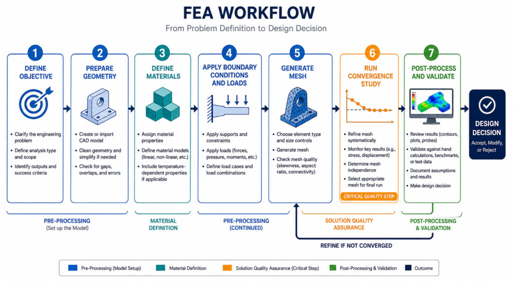
    1. Preprocessing: Creating the model, defining materials, and setting up boundary conditions
    2. Solving: The computer calculates the response of each element
    3. Post-processing: Visualizing and interpreting the results

    Types of FEA Analysis:

    • Structural Analysis: Stress, strain, and displacement under mechanical loads
    • Thermal Analysis: Heat transfer and temperature distribution
    • Modal Analysis: Natural frequencies and vibration modes
    • Fluid Dynamics: Fluid flow and pressure distribution
    • Fatigue Analysis: Prediction of failure under cyclic loading
    • Buckling Analysis: Stability under compressive loads

    When Your Project Needs FEA

    Critical Safety Applications

    FEA is essential when failure could result in injury, property damage, or loss of life. Industries such as aerospace, automotive, medical devices, and structural engineering rely heavily on FEA to ensure safety margins are adequate.

    Examples of Critical Applications:

    • Aircraft components subjected to extreme loads and temperatures
    • Automotive crash structures and safety systems
    • Medical implants that must withstand cyclic loading
    • Pressure vessels operating under high pressure and temperature
    • Structural elements in buildings and bridges

    High-Value Projects

    When development costs are high or failure would be extremely expensive, FEA provides valuable risk mitigation. The cost of simulation is typically a small fraction of the cost of physical testing or product failure in the field.

    Cost-Benefit Considerations:

    • Projects with expensive prototyping and testing requirements
    • Products with long development cycles where late-stage changes are costly
    • High-volume production where small improvements yield significant savings
    • Custom or one-off designs where testing isn’t practical

    Performance Optimization Requirements

    FEA excels at identifying optimization opportunities that aren’t obvious through traditional design methods. This is particularly valuable in competitive industries where performance advantages translate to market success.

    Optimization Scenarios:

    • Weight reduction while maintaining strength requirements
    • Improving thermal management in electronic devices
    • Minimizing vibration and noise in mechanical systems
    • Optimizing flow characteristics in fluid systems
    • Maximizing efficiency in rotating machinery

    Complex Loading Conditions

    When parts experience complex combinations of loads, temperatures, or environmental conditions, FEA provides insights that simple hand calculations cannot achieve.

    Complex Loading Examples:

    • Components subjected to multiple load paths simultaneously
    • Parts experiencing thermal cycling and mechanical stress
    • Structures under dynamic or impact loading
    • Systems with significant geometric nonlinearities
    • Assemblies with complex contact interactions

    Types of FEA and Their Applications

    Structural Analysis

    The most common type of FEA, structural analysis determines how parts deform and what stresses develop under mechanical loads.

    Linear Static Analysis:

    • When to Use: Small deformations, linear material behavior, steady loads
    • Applications: Basic strength verification, deflection calculations
    • Benefits: Fast computation, straightforward interpretation
    • Limitations: Cannot handle large deformations or nonlinear effects

    Nonlinear Analysis:

    • When to Use: Large deformations, material plasticity, contact problems
    • Applications: Crash analysis, forming simulations, rubber components
    • Benefits: Accurate representation of real-world behavior
    • Limitations: More complex setup, longer computation times

    Thermal Analysis

    Thermal FEA predicts temperature distributions and heat flow through structures, critical for managing thermal stresses and ensuring proper operation.

    Steady-State Thermal Analysis:

    • Applications: Electronics cooling, heat sink design, insulation effectiveness
    • Key Outputs: Temperature distribution, heat flux, thermal gradients
    • Design Insights: Hot spot identification, cooling optimization

    Transient Thermal Analysis:

    • Applications: Startup/shutdown cycles, thermal shock analysis
    • Key Outputs: Temperature vs. time, thermal cycling effects
    • Design Insights: Thermal stress development, cool-down strategies

    Modal Analysis

    Modal analysis identifies natural frequencies and mode shapes, essential for avoiding resonance problems and designing for dynamic stability.

    When Modal Analysis is Critical:

    • Rotating machinery operating near critical speeds
    • Structures subjected to dynamic loading
    • Systems requiring vibration isolation
    • Parts that must avoid specific frequency ranges

    Key Design Insights:

    • Natural frequency identification
    • Mode shape visualization
    • Damping requirements
    • Stiffness optimization strategies

    Fatigue Analysis

    Fatigue analysis predicts how long parts will last under cyclic loading, crucial for components that experience repeated stress cycles.

    Fatigue Analysis Applications:

    • Automotive suspension components
    • Aircraft structural elements
    • Rotating machinery shafts
    • Pressure vessel nozzles
    • Electronic component solder joints

    Fatigue Analysis Benefits:

    • Life prediction for maintenance scheduling
    • Identification of crack initiation sites
    • Optimization of stress concentrations
    • Material selection guidance

    Implementing FEA in Your Development Process

    Early-Stage Design Validation

    Incorporating FEA early in the design process provides maximum value by identifying issues when changes are still inexpensive to implement.

    Early-Stage FEA Benefits:

    • Concept feasibility verification
    • Material selection guidance
    • Preliminary sizing and optimization
    • Risk identification and mitigation

    Design Optimization

    FEA enables systematic design optimization that would be impractical with physical testing alone.

    Optimization Strategies:

    • Parametric Studies: Varying design parameters to understand sensitivities
    • Topology Optimization: Finding optimal material distribution
    • Shape Optimization: Refining geometry for improved performance
    • Multi-objective Optimization: Balancing competing requirements

    Virtual Testing and Validation

    FEA can supplement or replace physical testing in many scenarios, reducing development time and cost.

    Virtual Testing Advantages:

    • Test conditions that are difficult or dangerous to replicate physically
    • Evaluate multiple design variants quickly
    • Investigate failure mechanisms in detail
    • Reduce the number of physical prototypes required

    Common FEA Mistakes and How to Avoid Them

    Inadequate Model Validation

    One of the most serious mistakes is using FEA results without proper validation against known solutions or experimental data.

    Validation Best Practices:

    • Compare results to analytical solutions when available
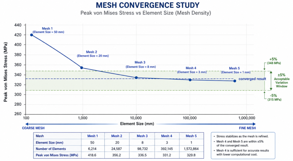
    • Perform mesh convergence studies
    • Validate against experimental data or previous designs
    • Check results for physical reasonableness

    Poor Mesh Quality

    The finite element mesh is the foundation of any FEA simulation. Poor mesh quality leads to inaccurate results and convergence problems.

    Mesh Quality Guidelines:

    • Use appropriate element types for the physics being analyzed
    • Refine mesh in high-stress regions
    • Maintain good aspect ratios and avoid highly distorted elements
    • Perform mesh convergence studies to ensure adequate refinement

    Inappropriate Boundary Conditions

    Boundary conditions must accurately represent the real-world constraints and loading conditions.

    Boundary Condition Best Practices:

    • Carefully consider how parts are actually supported and loaded
    • Avoid over-constraining the model
    • Use appropriate load distribution methods
    • Consider thermal expansion effects in constrained systems

    Ignoring Material Nonlinearities

    Many materials exhibit nonlinear behavior, especially at high stress levels or temperatures.

    Material Modeling Considerations:

    • Use appropriate material models for the loading conditions
    • Consider temperature effects on material properties
    • Account for strain rate sensitivity when applicable
    • Validate material models against test data

    Building FEA Capabilities

    In-House vs. Outsourced FEA

    Organizations must decide whether to develop internal FEA capabilities or outsource analysis work.

    In-House FEA Advantages:

    • Greater control over analysis timing and priorities
    • Better integration with design process
    • Accumulated knowledge and experience
    • Ability to perform iterative optimization

    Outsourced FEA Advantages:

    • Access to specialized expertise
    • No capital investment in software and hardware
    • Scalable capacity for project peaks
    • Independent validation of critical analyses

    Training and Skill Development

    Successful FEA implementation requires ongoing investment in training and skill development.

    Essential FEA Skills:

    • Understanding of fundamental mechanics and physics
    • Software-specific training and certification
    • Post-processing and results interpretation
    • Experimental validation techniques

    Software Selection Criteria

    Choosing the right FEA software depends on your specific needs, budget, and organizational capabilities.

    Key Selection Factors:

    • Types of analysis required
    • Integration with CAD systems
    • Ease of use and learning curve
    • Technical support and training availability
    • Total cost of ownership

    Future Trends in FEA

    Cloud-Based Simulation

    Cloud computing is making high-performance FEA more accessible to smaller organizations and enabling new collaborative workflows.

    AI and Machine Learning Integration

    Artificial intelligence is beginning to automate mesh generation, optimize solver settings, and interpret results, making FEA more accessible to non-experts.

    Real-Time Simulation

    Advances in computing power and algorithms are enabling real-time FEA for interactive design optimization and virtual reality applications.

    Multiphysics Integration

    Modern products often involve complex interactions between structural, thermal, electromagnetic, and fluid phenomena, driving demand for integrated multiphysics simulation.

    Conclusion

    Finite Element Analysis is a powerful tool that can significantly improve product quality, reduce development costs, and accelerate time to market when properly implemented. The key to success lies in understanding when FEA adds value, choosing appropriate analysis types, and following best practices for model development and validation.

    Whether your project involves ensuring safety-critical performance, optimizing designs for competitive advantage, or reducing development risk, FEA can provide the insights needed to make informed engineering decisions. The investment in FEA capabilities—whether in-house or through partnerships—often pays for itself many times over through improved products and reduced development cycles.

    At SimuTecra, we specialize in providing comprehensive FEA services across all major analysis types and industries. Our experienced team can help you determine when FEA is beneficial for your projects and provide the analysis and insights needed to optimize your designs. Contact us today to discuss how FEA can accelerate your product development and improve your competitive position.

  • 5 Essential Tips for Optimizing Your 3D Models for Manufacturing

    5 Essential Tips for Optimizing Your 3D Models for Manufacturing

    Introduction: From Digital Design to Physical Reality

    Creating a 3D model is just the first step in the product development process. To ensure your designs translate seamlessly from digital concept to physical product, you need to consider manufacturability from the very beginning. This approach, known as Design for Manufacturing (DFM), can save significant time, money, and headaches during production.

    In this comprehensive guide, we’ll explore five essential strategies that will help you optimize your 3D models for manufacturing, regardless of whether you’re working with injection molding, CNC machining, 3D printing, or other manufacturing processes.

    1. Design with Material Properties in Mind

    Understanding the properties and limitations of your chosen material is fundamental to creating manufacturable designs. Different materials have unique characteristics that directly impact how your part should be designed.

    Key Material Considerations:

    • Tensile Strength: Determines how much pulling force the material can withstand
    • Flexibility: Affects how the part will behave under stress and what minimum bend radii are possible
    • Thermal Properties: Important for parts that will experience temperature variations
    • Chemical Resistance: Critical for parts exposed to solvents, acids, or other chemicals
    • Surface Finish Requirements: Some materials naturally provide better surface finishes than others

    Practical Application:

    When designing a plastic housing for electronics, consider the thermal expansion of your chosen material. If the housing will be exposed to temperature variations, design appropriate clearances to prevent stress cracking. For metal parts, consider the material’s work hardening characteristics during forming operations.

    Material Selection Best Practices:

    1. Research material datasheets thoroughly before beginning design
    2. Consider the entire product lifecycle, not just initial performance requirements
    3. Consult with material suppliers about specific applications
    4. Factor in material availability and lead times
    5. Consider secondary operations that may be affected by material choice

    2. Optimize Wall Thickness and Feature Sizing

    Proper wall thickness is crucial for both manufacturability and part performance. Too thin, and you risk weak points or manufacturing difficulties. Too thick, and you may encounter issues like sink marks, long cycle times, or excessive material costs.

    General Guidelines by Manufacturing Process:

    Injection Molding:

    • Maintain uniform wall thickness when possible (typically 1-4mm for most plastics)
    • Use gradual transitions between different thicknesses
    • Add ribs for structural support rather than increasing overall wall thickness
    • Consider gate placement and flow patterns

    CNC Machining:

    • Ensure minimum wall thickness can be achieved with available tooling
    • Consider tool access and clearance requirements
    • Design features that can be machined in minimal setups
    • Avoid deep, narrow pockets that require specialized tooling

    3D Printing:

    • Follow printer-specific minimum feature size guidelines
    • Consider support structure requirements for overhangs
    • Design self-supporting features when possible
    • Account for layer adhesion direction in structural elements

    Advanced Wall Thickness Strategies:

    Use simulation tools to analyze flow patterns in injection molding or stress distributions in mechanical parts. This data-driven approach helps optimize wall thickness for both manufacturability and performance.

    3. Incorporate Proper Draft Angles and Undercuts

    Draft angles are essential for parts that need to be removed from molds or machined cavities. Proper draft not only facilitates part removal but also improves surface finish and extends tool life.

    Draft Angle Guidelines:

    • Injection Molding: Minimum 0.5° per side, with 1-3° being typical
    • Die Casting: 1-3° minimum, depending on part depth
    • Sand Casting: 3-5° or more, depending on pattern complexity
    • Machining: Consider tool taper and spindle deflection

    Managing Undercuts:

    Undercuts can significantly increase manufacturing complexity and cost. When undercuts are necessary:

    1. Evaluate if the undercut can be eliminated through design changes
    2. Consider secondary operations like machining or assembly
    3. Design for side actions or slides in molding applications
    4. Use collapsible cores for internal undercuts when possible

    Alternative Design Strategies:

    • Split parts to eliminate undercuts
    • Use snap-fit assemblies instead of integral features
    • Design removable components for complex geometries
    • Consider post-processing operations like ultrasonic welding

    4. Plan for Tolerances and Fit Requirements

    Tolerance planning is often overlooked in early design phases but is critical for manufacturable designs. Understanding the capabilities and limitations of your chosen manufacturing process helps you specify realistic tolerances that balance functionality with cost.

    Manufacturing Process Capabilities:

    CNC Machining:

    • General tolerance: ±0.005″ (±0.13mm)
    • Precision tolerance: ±0.001″ (±0.025mm) with additional cost
    • Surface finish: 32-125 μin Ra typically achievable

    Injection Molding:

    • General tolerance: ±0.002-0.005″ per inch
    • Precision molding: ±0.001″ possible with premium tooling
    • Consider shrinkage variations across part geometry

    3D Printing:

    • FDM: ±0.005″ (±0.13mm) typically achievable
    • SLA/SLS: ±0.002″ (±0.05mm) for small features
    • Consider layer height and orientation effects

    Tolerance Optimization Strategies:

    1. Apply the loosest tolerances that still meet functional requirements
    2. Use geometric dimensioning and tolerancing (GD&T) for complex relationships
    3. Consider assembly sequence and cumulative tolerances
    4. Plan for secondary operations if tight tolerances are required
    5. Document critical dimensions clearly for manufacturing teams

    Fit and Assembly Considerations:

    Design clearances appropriate for your manufacturing process and assembly requirements. Consider thermal expansion, wear, and lubrication requirements when specifying fits between mating parts.

    5. Consider Assembly and Post-Processing Requirements

    Designing individual components is only part of the challenge—successful products require careful consideration of how parts will be assembled and what post-processing operations may be necessary.

    Assembly-Friendly Design Features:

    • Alignment Features: Include pins, slots, or chamfers to guide assembly
    • Access Clearances: Ensure tools and hands can reach fasteners and connection points
    • Visual Indicators: Design features that make correct assembly obvious
    • Mistake-Proofing: Use asymmetric features to prevent incorrect assembly

    Fastener and Connection Strategy:

    Choose fasteners and connection methods that balance assembly time, disassembly requirements, and manufacturing cost:

    • Minimize the number of fastener types and sizes
    • Consider snap-fit connections for permanent assemblies
    • Design for standard tools and equipment
    • Plan for serviceability if maintenance is required

    Post-Processing Planning:

    Many parts require post-processing operations to meet final specifications:

    Surface Finishing:

    • Design surfaces that can be efficiently finished
    • Consider masking requirements for selective finishing
    • Plan for fixturing during finishing operations
    • Specify appropriate surface textures for functionality

    Secondary Machining:

    • Design reference surfaces for consistent setup
    • Minimize the number of setups required
    • Consider how clamping forces will affect part geometry
    • Plan for material removal and chip evacuation

    Quality Control Considerations:

    Design features that facilitate inspection and quality control:

    • Include accessible datums for measurement
    • Design test features for functional verification
    • Consider non-destructive testing requirements
    • Plan for statistical process control measurements

    Implementation Strategies

    Early Collaboration:

    Involve manufacturing engineers and suppliers early in the design process. Their expertise can help identify potential issues before they become costly problems.

    Prototyping and Validation:

    Use rapid prototyping to validate manufacturability assumptions and test assembly procedures before committing to production tooling.

    Design Reviews:

    Conduct formal design reviews with cross-functional teams including manufacturing, quality, and assembly personnel.

    Continuous Improvement:

    Collect feedback from production and incorporate lessons learned into future designs.

    Conclusion

    Optimizing 3D models for manufacturing requires a holistic approach that considers material properties, manufacturing processes, assembly requirements, and quality specifications from the earliest design stages. By following these five essential strategies, you can significantly reduce development time, manufacturing costs, and production risks.

    Remember that manufacturability is not just about making parts that can be produced—it’s about designing parts that can be produced efficiently, consistently, and cost-effectively while meeting all performance requirements.

    At SimuTecra, we specialize in design for manufacturing services that help our clients bring products to market faster and more efficiently. Our experienced team can review your designs and provide recommendations for improved manufacturability across a wide range of production processes. Contact us today to learn how we can help optimize your next product for successful manufacturing.