
If you have ever asked a CAD engineer to model a part and received a file that looks perfect on screen but causes errors the moment you try to run an analysis or send it to a machine shop, there is a reasonable chance the model was built as surfaces rather than solids. The difference is invisible to the eye and critical in practice.
3D solid modeling and 3D surface modeling are two fundamentally different approaches to representing geometry in a CAD environment. Most engineers working in product design and manufacturing use 3D solid modeling as their primary method. Surface modeling is a specialist technique that solves problems solid modeling cannot. Understanding the difference, what each approach actually is, how each one is built, and what it can and cannot do, makes you a better client, a better collaborator, and a better decision-maker when 3D CAD is involved in your project.
What Is 3D Solid Modeling?
A solid model is a complete, closed, mathematically watertight representation of a three-dimensional object. When you build a solid model of a steel bracket, the CAD system does not just know the shape of its outer surfaces, it knows that the bracket has volume, that it is enclosed on all sides, and that every point in space is either inside the part or outside it. There is no ambiguity.
This matters because it means the CAD system can calculate mass properties from the model directly. Volume, mass, centre of gravity, moments of inertia, all of these flow automatically from a 3D solid modeling given a material density. It also means the model can be used directly for finite element analysis, for generating manufacturing drawings with proper section views, and for producing toolpaths for CNC machining without any intermediate conversion steps.
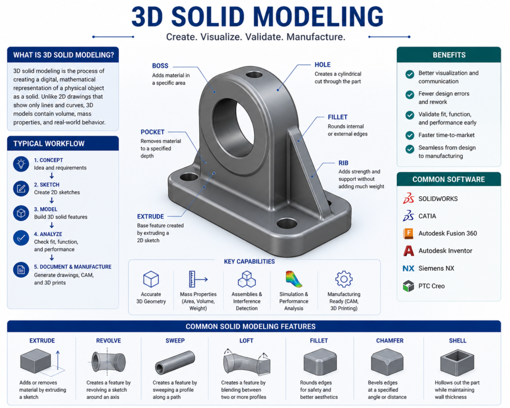
In most modern CAD platforms, SolidWorks, CATIA, NX, Creo, Inventor, solid models are built parametrically. This means the model is constructed as a sequence of features: a base extrusion, then a cut, then a fillet, then a pattern of holes. Each feature is driven by a sketch with defined dimensions. Change a dimension in the sketch and the model updates automatically throughout. This is what engineers mean when they talk about a parametric solid model, the geometry is defined by parameters, and the parameters are editable.
| A parametric solid model is not just a shape. It is a design with editable intent. The dimensions that define the model can be changed, and the entire model updates to reflect them. This is what makes 3D solid modeling the backbone of professional product development, the design can evolve without being rebuilt from scratch. |
Most manufactured parts, machined components, sheet metal parts, injection moulded housings, structural steel members, castings, are modeled as solids. If you are commissioning a 3D model for a part that will be manufactured, a solid model is almost always the right output.
What Is 3D Surface Modeling?
A surface model is built from individual surface patches, mathematical representations of curved or flat surfaces that have no thickness and no volume on their own. Think of it as modeling the skin of an object without any concern for what is inside. Each surface exists independently. The model only becomes a closed solid if all the surfaces are stitched together without gaps or overlaps to form a watertight shell, and that process is often a deliberate additional step, not an automatic one.
Surface modeling gives designers a level of control over complex curves and freeform geometry that solid modeling tools struggle to match. When the shape itself is the primary engineering requirement, the curvature of a car door, the aerodynamic profile of a wing, the ergonomic sweep of a consumer product, surface modeling allows that shape to be defined precisely, adjusted smoothly, and analysed for curvature continuity in ways that parametric solid features cannot easily achieve.
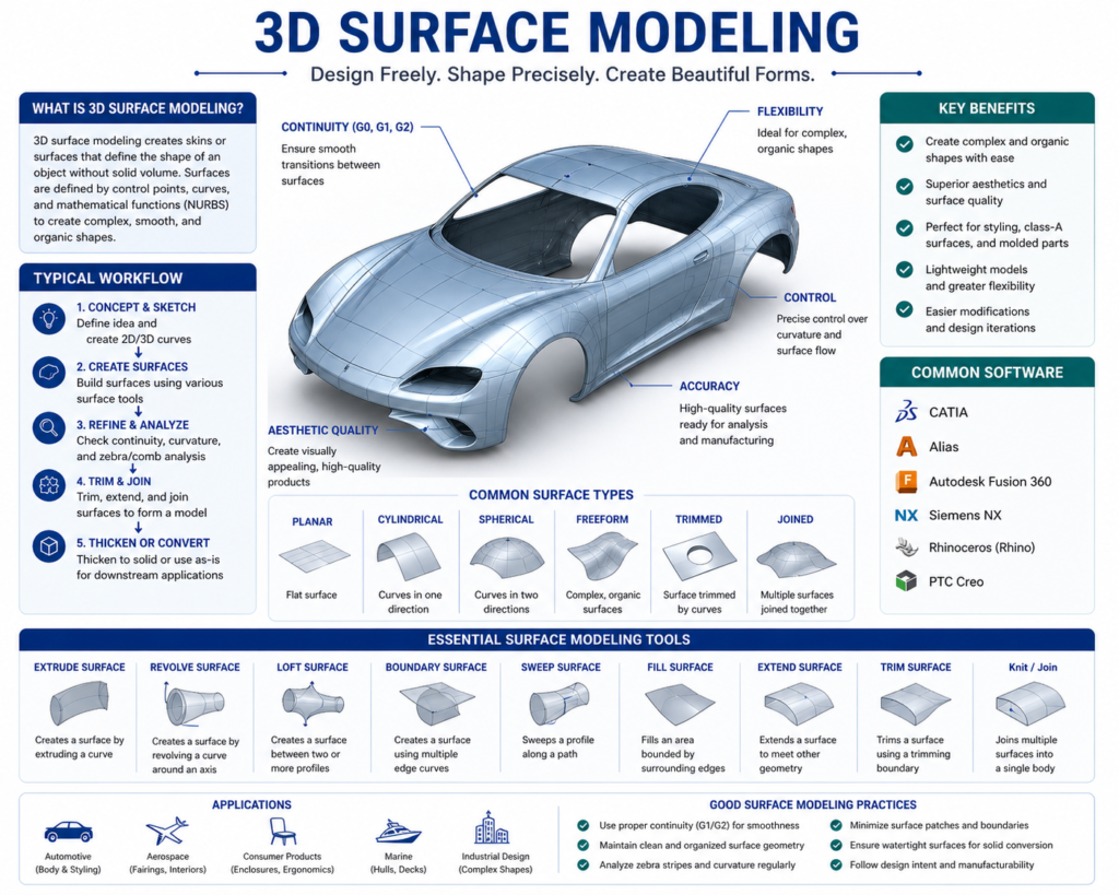
The tools most associated with surface modeling are Rhino3D (widely used in product design and architecture), Autodesk Alias (the industry standard for automotive exterior design), and the surfacing workbenches within CATIA and SolidWorks. These tools prioritise control over complex geometry rather than the feature-history structure of parametric solid modeling.
| Surface modeling is not a simpler version of solid modeling. It is a different discipline with different tools, different workflows, and different outputs. A designer who is highly skilled in SolidWorks solid modeling may have limited experience with advanced surface modeling, and vice versa. When you need complex surface work done, specify it explicitly. |
The Real Difference: What Each Approach Can and Cannot Do
The practical distinction between solid and surface modeling comes down to what you can do with each model after it is built. This is where the choice becomes consequential for manufacturing, analysis, and downstream engineering work.
A solid model can be handed directly to a manufacturing engineer. They can derive 2D detail drawings from it with section views, dimensions, and GD&T callouts. They can run finite element analysis on it. They can generate CNC toolpaths from it. They can check interference with adjacent components in an assembly. They can 3D print it immediately by exporting to STL. All of this works because the model is defined as a closed volume.
A surface model, in its raw form, cannot do most of those things. You cannot run FEA on an open surface, the analysis requires a closed volume to apply boundary conditions and calculate stress distribution through a material. You cannot derive a useful section view from a surface model that has no interior. CNC machining is possible but requires the surfaces to be closed and watertight. 3D printing requires the model to be converted to a solid first.
This does not mean surface models are less useful, it means they serve a different stage of the workflow. In many high-end product development processes, the design starts as a surface model (defining the shape and aesthetics precisely), and that surface model is then used as a reference to build a solid model underneath it. The surface defines the intent; the solid enables the engineering.
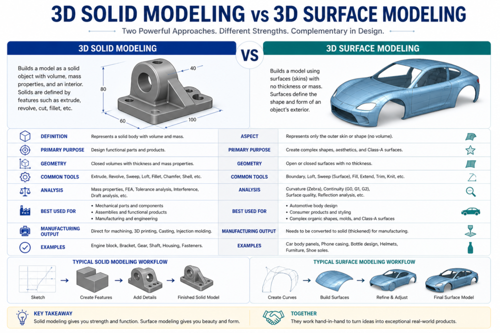
Solid Modeling vs Surface Modeling: Side-by-Side
| Property | Solid Modeling | Surface Modeling |
| What it defines | Closed, watertight volume with mass | Open or closed surfaces with no implied volume |
| Mass properties | Yes, volume, mass, centre of gravity calculable | No, surfaces have no inherent volume or mass |
| FEA / simulation | Yes, directly usable for structural and thermal analysis | Requires conversion to solid first |
| Manufacturing output | Full manufacturing drawings, toolpaths, GD&T | Toolpaths possible but requires watertight closure first |
| Typical use | Mechanical parts, structural components, assemblies | Aerodynamic shapes, consumer product aesthetics, complex curves |
| Parametric editing | Yes, feature-based history in most platforms | Yes, but surface tools are more freeform and less constrained |
| Common tools | SolidWorks, CATIA, NX, Creo, Inventor | Rhino, Alias, CATIA Freestyle, SolidWorks surfacing tools |
| File output | STEP, native CAD, STL (for printing) | STEP (surfaces), IGES, native CAD, STL requires watertight closure |
A Real-World Example: Designing an Industrial Pump Casing
Consider the design of an industrial pump casing, a component that needs to contain pressurised fluid, mount to a motor face, and connect to inlet and outlet pipework. This is exactly the kind of part where both approaches touch the project, for different reasons.
| Stage 1: Solid Modeling for the Structural Casing The casing body, its wall thickness, mounting flanges, bolt hole pattern, and internal fluid passages, is built as a parametric solid model in SolidWorks. This allows the engineer to run a pressure vessel FEA to verify that the wall thickness is adequate under operating pressure. They can derive manufacturing drawings with proper section views showing the internal passage geometry. The solid model feeds directly into the CNC machining workflow for the external features and the turning programme for the bore. Mass properties are calculated automatically to check that the casing weight is within the installation limit. |
| Stage 2: Surface Modeling for the Volute ProfileThe internal volute, the spiral passage that converts fluid velocity to pressure, requires a precisely controlled curved surface that solid feature tools cannot define accurately enough. The fluid dynamics team defines the volute geometry as a surface model, optimising the curvature for hydraulic efficiency. This surface is then imported into the solid model and used as a cutting reference to create the internal passage geometry. The surface defined the shape; the solid model used it for manufacturing. |
The same product. Two modeling approaches. Each used where it was the right tool for the specific requirement. This is how experienced engineering teams think about it, not as an either/or choice, but as a question of which approach serves each part of the design problem.
When to Use Solid Modeling and When to Use Surface Modeling
For most mechanical engineering and manufacturing projects, solid modeling is the right approach. If the primary questions about a part are how strong it is, how it is manufactured, how it assembles with adjacent components, and whether it can be dimensioned and toleranced for production, solid modeling answers all of those questions directly.
Surface modeling becomes the right choice, or a necessary complement, in specific situations:
- The shape itself is the primary engineering requirement. Aerodynamic profiles, hydrodynamic surfaces, ergonomic consumer product forms, and automotive exterior panels all require surface modeling tools to define and control the geometry with the precision the design demands.
- The geometry cannot be created with standard solid features. Some complex organic shapes, smooth multi-tangent blends, and continuously curved transitions are simply not achievable with extrusions, revolves, and sweeps. Surface modeling gives the designer the tools to define these geometries explicitly.
- The project involves styling or industrial design as a precursor to engineering. Many product development processes start with a styling model built in surfacing tools, which is then handed to the engineering team to develop into a solid model for manufacturing. The surface model defines the visual and ergonomic intent; the solid model delivers the engineering.
- You are working with imported geometry that has surface errors. When a STEP or IGES file arrives with gaps, overlaps, or missing faces, surface modeling tools are used to repair and close the geometry before it can be used as a solid.
| If you are asking a CAD engineer to model a machined component, a fabricated assembly, or a structural part, request a solid model. If you are asking them to define a complex freeform shape, an aerodynamic profile, or a consumer product exterior, discuss surface modeling explicitly and confirm whether the output will be a surface or a closed solid suitable for manufacturing. |
What This Means When You Commission a 3D Model
The modeling approach directly affects what you can do with the output. Before commissioning 3D CAD work, it is worth being clear on three questions:
- What will the model be used for? If the answer is manufacturing drawings and FEA, you need a solid. If the answer is a rendering for a client presentation, a surface model may be sufficient. If the answer is both, you need a solid built to manufacturing standards.
- Will the model need to be edited later? A parametric solid model built with proper feature structure can be modified efficiently as the design evolves. A surface model, or a solid model built without parametric discipline, may need to be substantially rebuilt to accommodate changes.
- What file formats will be delivered? A STEP file from a solid model and a STEP file from a surface model are not equivalent. Confirm whether the delivered geometry is a closed solid body or a collection of surfaces, particularly if you are passing the file to a machine shop or running it through simulation software.
These are not difficult questions to ask, but they are ones that frequently go unasked, and the answers have a direct impact on whether the model you receive is fit for purpose at the next stage of your project.
As of 2026, the choice between solid and surface modeling depends heavily on the intended application, with specialized software leading in each category
Auto Desk Forum
Frequently Asked Questions
Is solid modeling always better than surface modeling?
No. Solid modeling is better for manufacturing-focused work, structural parts, machined components, assemblies, anything that needs FEA or manufacturing drawings. Surface modeling is better for complex freeform geometry where controlling the precise curvature of a surface is the primary design requirement. Many professional workflows use both, with surface modeling defining the shape and solid modeling delivering the engineering.
Can a surface model be converted to a solid model?
Yes, if the surfaces form a completely closed, watertight shell with no gaps or overlaps. Most CAD platforms have tools to stitch surfaces into a solid automatically when the geometry allows it. When surfaces have errors, small gaps, mismatched edges, or overlapping patches, they must be repaired manually before the conversion is possible. Receiving a STEP file of surfaces from an external source and converting it to a usable solid is a common but sometimes time-consuming task.
What does ‘parametric’ mean in solid modeling?
A parametric solid model is built from features that are driven by editable dimensions and relationships. If you change the diameter of a hole from 10 mm to 12 mm, the model updates, along with any features that reference that hole. Parametric modeling is the foundation of efficient design iteration: changes propagate through the model automatically rather than requiring manual rebuilds. Non-parametric models, sometimes called dumb solids, have correct geometry but no editable feature structure. They can be modified by pushing and pulling faces, but they do not carry the original design intent.
Does 3D printing need a solid model or a surface model?
3D printing requires the model to be exported as an STL file, which is a mesh representation. To produce a valid STL, the underlying geometry must be a closed, watertight solid, or at minimum, a closed set of surfaces with no holes. A solid model exports to a valid STL reliably. An open surface model will produce an invalid STL that slicing software cannot process correctly. If your model has been built as open surfaces, it must be closed before 3D printing.
What CAD software is used for solid modeling vs surface modeling?
SolidWorks, CATIA, NX (Siemens), Creo, and Autodesk Inventor are the dominant platforms for parametric solid modeling in manufacturing and mechanical engineering. For surface modeling, Rhino3D and Autodesk Alias are the specialist tools, Alias is the standard in automotive exterior design. CATIA and NX both include advanced surfacing workbenches used in aerospace and high-end automotive work. SolidWorks also includes a surfacing module for users who need surface capabilities alongside their solid modeling workflow.
The Bottom Line
Solid modeling and surface modeling are not competing methods, they are complementary tools that solve different problems. Solid modeling is the foundation of mechanical engineering and manufacturing: it defines closed volumes, enables analysis, and drives manufacturing documentation. Surface modeling is the specialist’s tool for complex geometry where the precise control of curvature matters more than the structural properties of the result.
For the majority of engineering and manufacturing projects, a parametric solid model is what you need. When the geometry becomes complex enough that solid features cannot define it accurately, or when the shape itself is the primary design deliverable, surface modeling becomes necessary. Understanding which you are working with, and which you need, means your 3D CAD work is fit for its purpose from the moment the file is delivered.
| Need 3D Models Built the Right Way for Manufacturing? At Simutecra Engineering Services, we build parametric solid models and surface models depending on what your project actually requires, not just what is quickest to produce. Every model is built with downstream use in mind: whether that is FEA analysis, CNC machining, sheet metal fabrication, or full manufacturing drawing production. Share your project brief and we will advise on the right modeling approach from the start. |
Leave a Reply