Ask ten people what a mechanical engineer does and you will likely get ten different answers. Some will say they design cars. Others will say they build machines. A few might mention robots or rockets. All of them would be at least partially right, which says everything about just how broad this profession actually is.
The honest answer is that mechanical engineering is one of the most diverse engineering disciplines in existence. A mechanical engineer working at a Formula 1 team and a mechanical engineer working at a medical device startup are both doing mechanical engineering, yet their daily tasks, tools, challenges, and outputs could hardly look more different.
This guide cuts through the vagueness. We will break down exactly what mechanical engineers do, day by day and role by role, what problems they are paid to solve, what skills they need, what a typical week looks like at different career stages, and how the job varies across industries. Whether you are considering a career in engineering, hiring a mechanical engineer, or simply curious about the profession, this is the most complete and practical breakdown you will find.
| Quick Answer: A mechanical engineer designs, analyzes, builds, tests, and improves mechanical systems and devices. They apply principles of physics, thermodynamics, materials science, and mathematics to create solutions to real-world physical problems, from individual components to large complex systems. |

The Core Job of a Mechanical Engineer
At its most fundamental level, the job of a mechanical engineer is to take a physical problem or need and design a reliable, efficient, and manufacturable solution for it. That sounds simple, but the range of physical problems that fall under mechanical engineering is enormous.
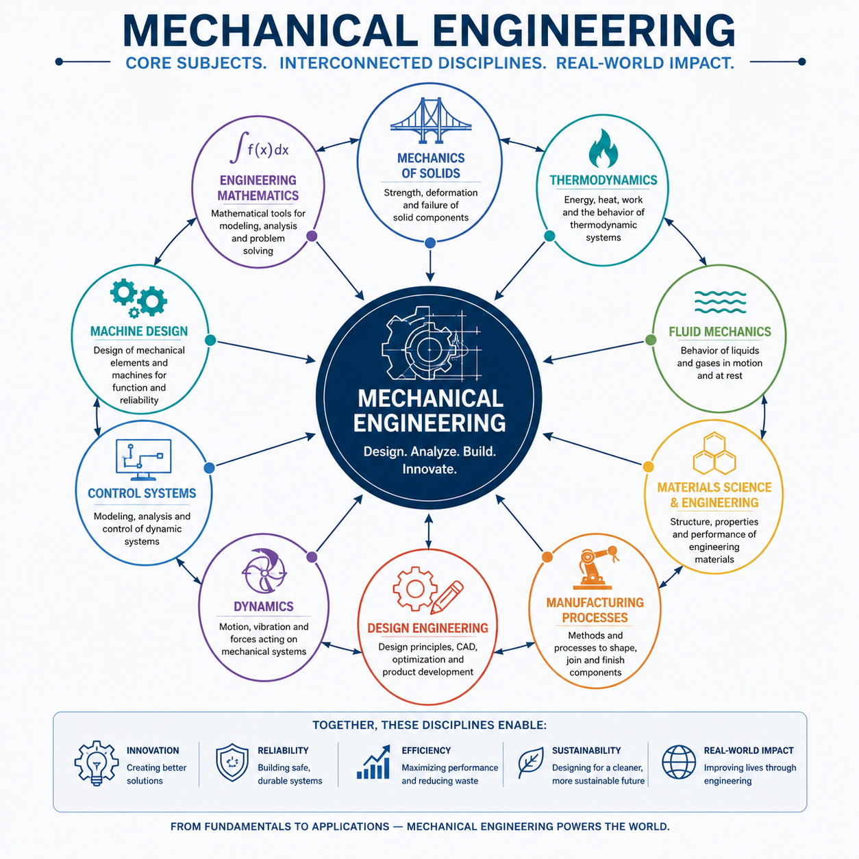
Mechanical engineers work with forces, motion, heat, fluids, and materials. They design systems that generate power, transfer energy, move loads, control temperature, or manipulate objects. They use mathematics and physics to predict how their designs will behave before anything physical is built, and they use physical testing and prototyping to verify those predictions.
The profession can be broadly divided into three core activities that repeat across almost every role and industry:
| Core Activity | What It Involves | Example |
| Design | Creating concepts, developing detailed designs, producing engineering drawings and CAD models | Designing a new heat exchanger for an HVAC system |
| Analysis | Using calculations, simulation, and testing to verify that a design meets its performance and safety requirements | Running FEA on a bracket to confirm it will not fail under load |
| Development & Improvement | Refining existing products, resolving field failures, optimizing performance or cost | Redesigning a pump seal to eliminate leaks reported by customers |
These three activities form a continuous cycle. Engineers design, analyze their design, build or test it, learn from the results, and then improve or redesign. Even a highly experienced engineer rarely gets a design perfect on the first attempt, so structured iteration is a core part of the engineering process.
What Mechanical Engineers Actually Do Day to Day
If you want to understand what mechanical engineering really looks like in practice, the best way is to walk through the kinds of tasks that appear on an engineer’s schedule on a regular basis. These vary by role and seniority, but the following activities are common across most mechanical engineering positions.
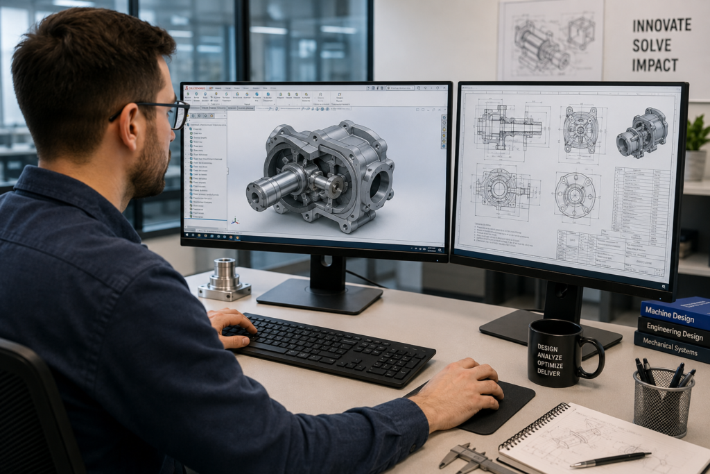
Working in CAD Software
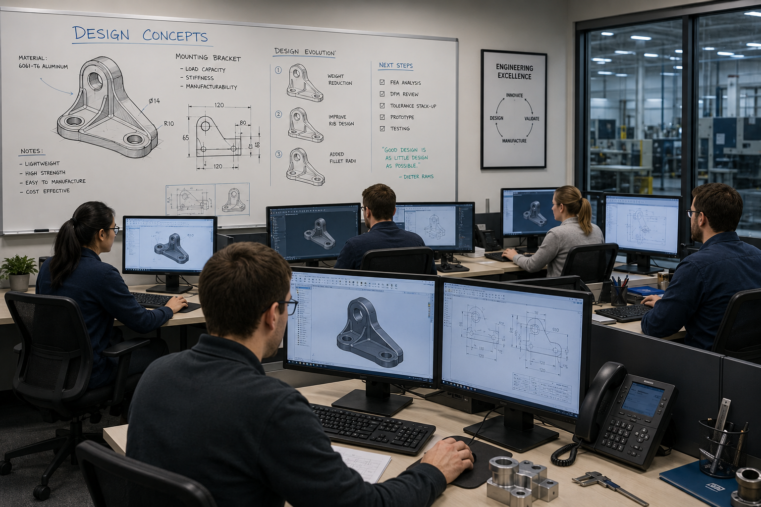
Computer-Aided Design is the primary technical tool for most mechanical engineers involved in product development. A typical engineer might spend anywhere from two to six hours a day inside a CAD environment such as SolidWorks, CATIA, or AutoCAD, creating new parts, modifying existing designs, building assemblies, checking fits and clearances, and generating engineering drawings for manufacturing.
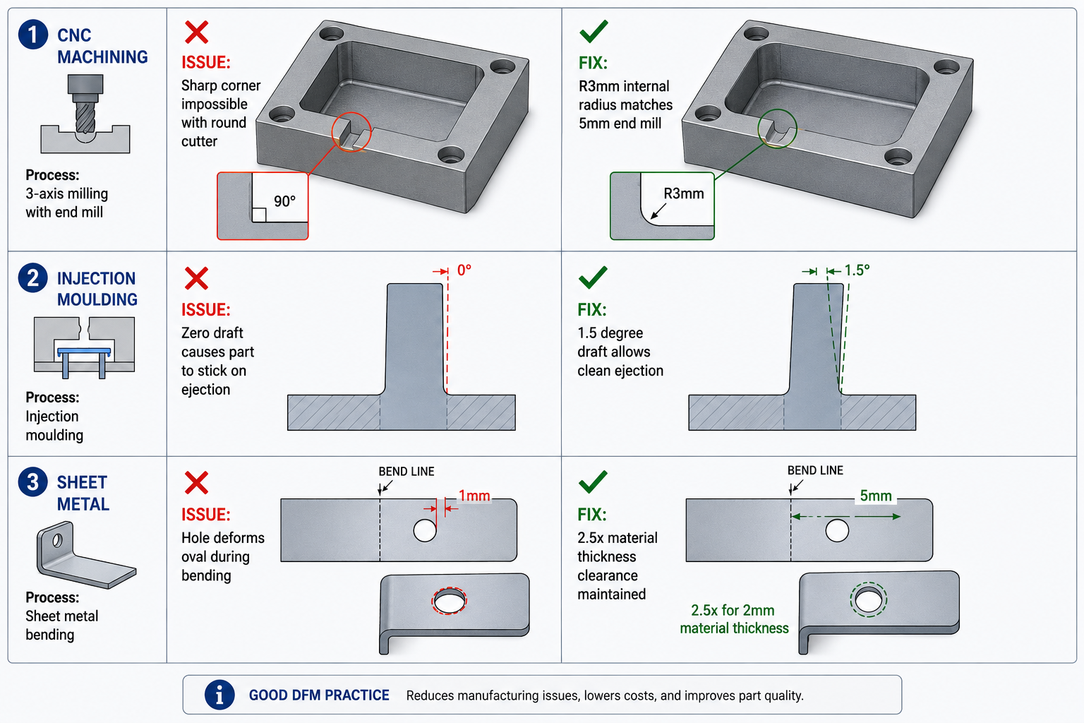
CAD work is not just about drawing shapes. Good CAD practice involves designing parts that are easy to manufacture, assemble, and service. An engineer who understands manufacturing constraints and design for assembly principles will create significantly better CAD models than one who designs in isolation.
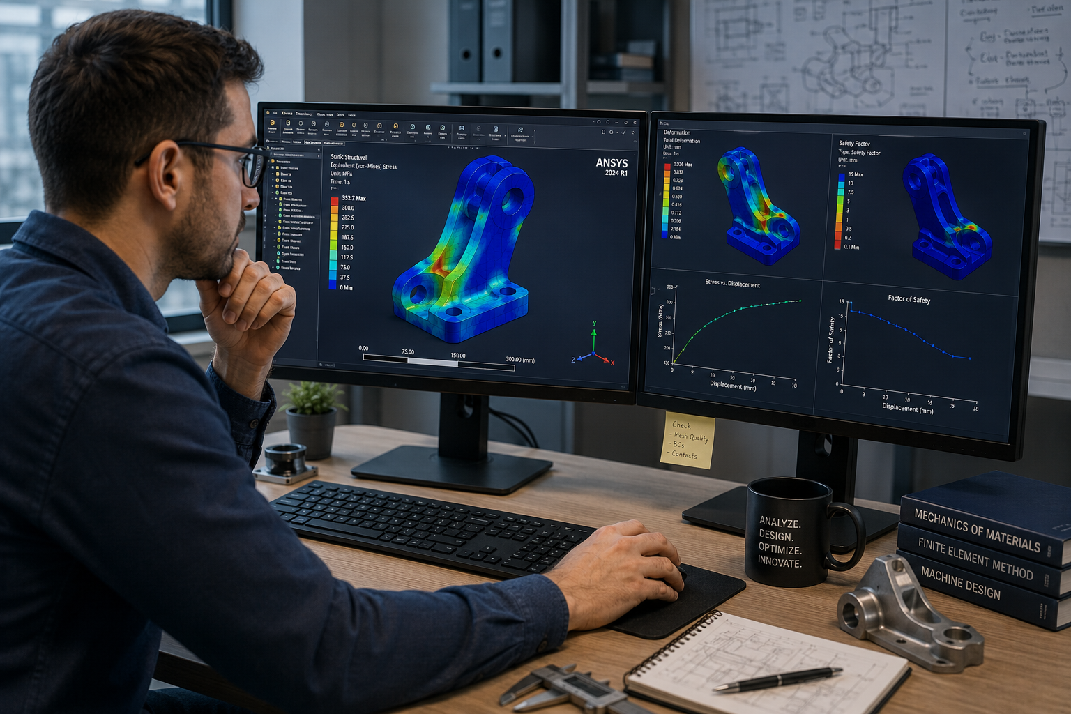
Running Calculations and Simulations
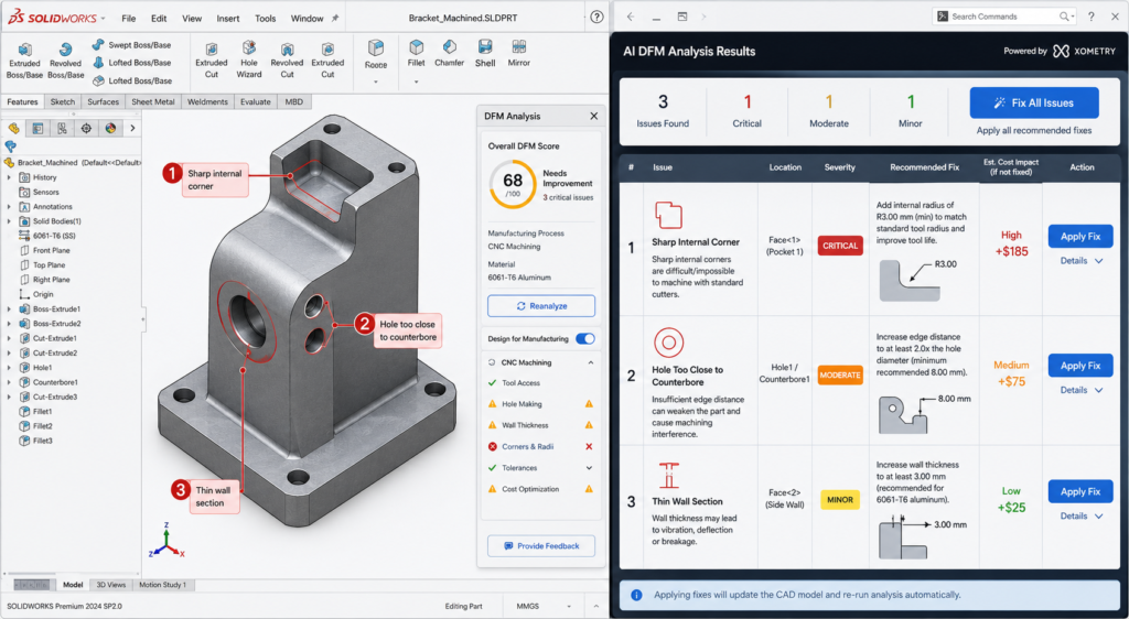
Before a design goes to manufacturing or physical testing, engineers use mathematical calculations and simulation software to predict how it will perform. This might involve hand calculations using textbook formulas, spreadsheet-based analysis, or advanced software tools such as ANSYS for Finite Element Analysis (FEA) or Computational Fluid Dynamics (CFD).
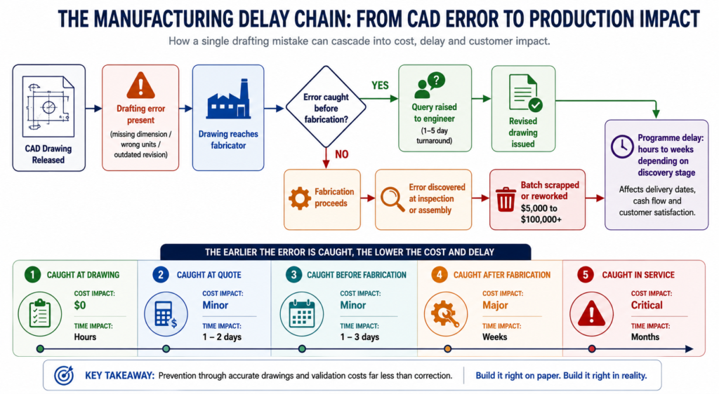
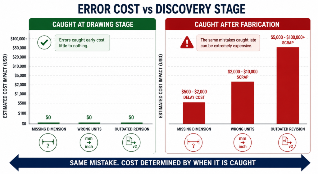
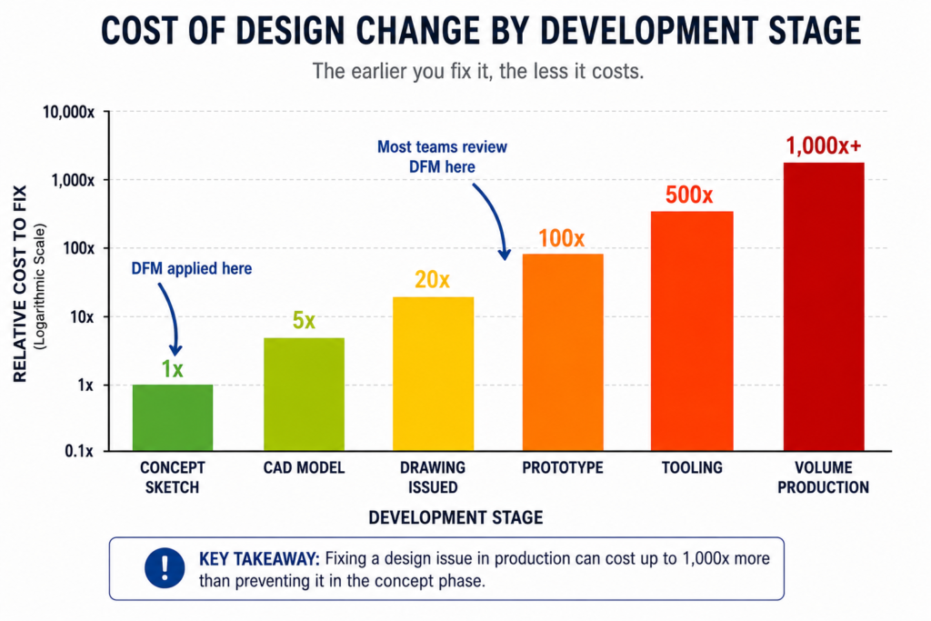
The purpose of simulation is to catch problems early, when they are cheap and easy to fix, rather than discovering failures during testing or, worse, in the field after a product has been released to customers. A well-run simulation phase can save weeks of physical testing and significant costs.
Writing and Reviewing Technical Documents
Engineering is a profession built on documentation. Mechanical engineers regularly produce and review technical reports, design specifications, test plans, failure analyses, and engineering change requests. These documents are essential for communicating designs clearly to colleagues, suppliers, regulators, and customers.
Strong technical writing is a skill that distinguishes good engineers from great ones. An engineer who can explain complex technical decisions clearly in writing is far more effective than one who can only communicate verbally or informally.
Attending Design Reviews and Technical Meetings
Mechanical engineering is a collaborative profession. Engineers regularly participate in design review meetings where a design is examined by a cross-functional team that might include other engineers, project managers, manufacturing specialists, quality engineers, and commercial representatives. These meetings exist to catch problems that an individual engineer might miss when working alone.
Formal design review processes such as Preliminary Design Reviews (PDRs), Critical Design Reviews (CDRs), and Design Failure Modes and Effects Analysis (DFMEA) sessions are common in industries like aerospace, automotive, and medical devices.
Working with Suppliers and Manufacturing
Designs do not build themselves. Mechanical engineers spend meaningful time communicating with suppliers about material specifications, tolerances, surface finishes, and lead times. They also work closely with internal manufacturing teams to ensure designs can be produced efficiently and to the required quality level.
This supplier and manufacturing interface is an area where junior engineers often underestimate the importance of relationship-building and clear communication. Understanding what a supplier or machine shop can and cannot do is as important as understanding the design itself.
Physical Testing and Prototyping
No amount of simulation replaces the insight gained from building and testing something in the real world. Mechanical engineers design test rigs, write test procedures, instrument prototypes with sensors, run tests, and analyse the data. This might involve testing structural strength, thermal performance, vibration characteristics, fluid flow behaviour, or fatigue life.
Test data feeds back into the design cycle. Discrepancies between simulation predictions and test results often reveal important insights about material behaviour, manufacturing variation, or the limitations of the simulation model.
Problem Solving and Root Cause Analysis
When something goes wrong, whether it is a product failure in the field, a production quality problem, or a design that does not meet its performance targets, mechanical engineers are called on to diagnose the cause and develop a fix. Root cause analysis techniques such as the 5 Whys, fishbone diagrams, and fault tree analysis are standard tools in the engineer’s problem-solving toolkit.
Key Responsibilities Across the Engineering Lifecycle
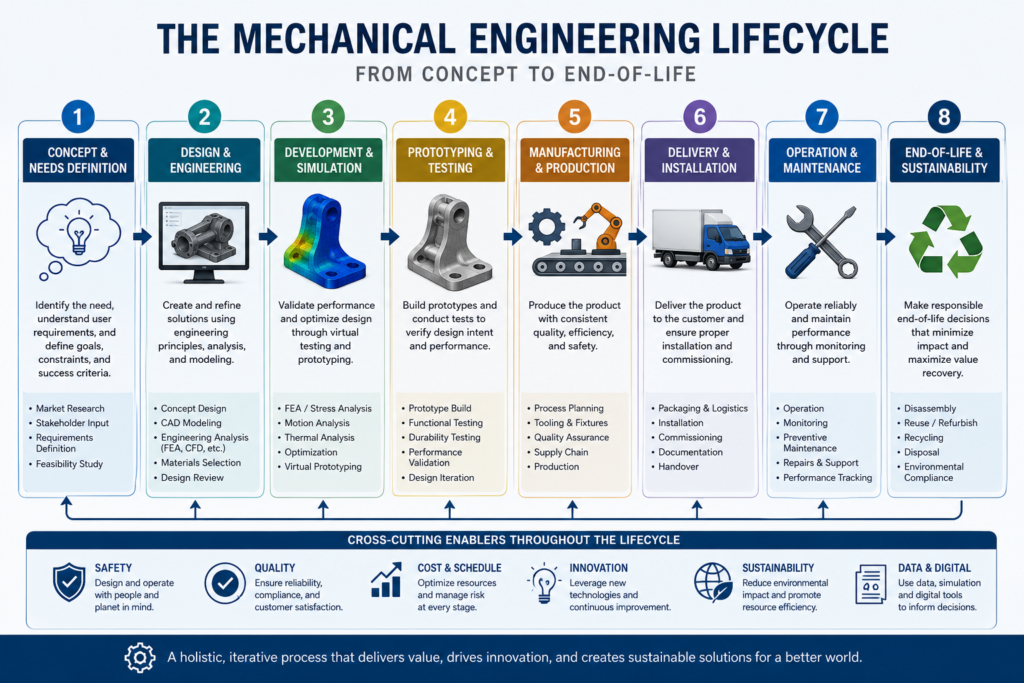
Mechanical engineers are typically involved at multiple stages of a product’s life, from the initial concept right through to end-of-life considerations. The responsibilities shift at each stage.
| Lifecycle Stage | Mechanical Engineer’s Key Responsibilities |
| Concept and Feasibility | Generating design concepts, assessing technical feasibility, estimating costs and timelines, creating initial CAD sketches or layouts |
| Detail Design | Developing fully detailed 3D CAD models and 2D drawings, specifying materials and tolerances, conducting FEA and CFD analysis, preparing design documentation |
| Prototyping | Overseeing prototype build, designing test equipment, writing test plans, conducting physical testing, analysing and reporting results |
| Manufacturing Ramp-Up | Supporting production with DFM feedback, resolving manufacturing issues, creating assembly procedures, training production staff |
| Product in Service | Investigating field failures, issuing engineering change requests, providing technical support to service teams and customers |
| End of Life | Advising on disassembly, material recovery, and sustainable disposal options as part of lifecycle engineering practice |
Types of Mechanical Engineers and Their Specific Roles
Because mechanical engineering is so broad, engineers typically specialise in a particular area after completing their general education. The following specialisations represent some of the most common and in-demand types of mechanical engineers.
Design Engineer
Design engineers focus on the creation of new products or the improvement of existing ones. They spend the majority of their time in CAD software and are the primary authors of engineering drawings and product specifications. Strong spatial reasoning, attention to detail, and a deep understanding of manufacturing processes are essential in this role.
Stress and Structural Analyst
Stress analysts use FEA and hand calculations to verify that components and structures can safely withstand their operating loads throughout their intended service life. This role is particularly common in aerospace, defence, automotive, and pressure vessel industries where structural failure can have catastrophic consequences. A stress analyst must be able to read FEA results critically and understand the limitations of numerical simulation.
Thermal and Fluids Engineer
Thermal and fluids engineers specialise in heat transfer, thermodynamics, and fluid mechanics. They design cooling systems for electronics, power generation equipment, and HVAC systems. They also work on fuel systems, hydraulic circuits, and aerodynamic shapes. CFD simulation is a primary tool for this type of engineer.
Manufacturing and Process Engineer
Manufacturing engineers focus on how products are made rather than what they look like. They optimise production processes, reduce waste, improve quality, and implement lean manufacturing and Six Sigma methodologies. This role sits at the interface of engineering and operations and is critical for companies that need to manufacture products at scale and at competitive cost.
Mechatronics and Robotics Engineer
Mechatronics engineers work at the intersection of mechanical, electrical, and software engineering. They design robots, automated machinery, and electromechanical systems. This role has grown enormously in importance over the past two decades as automation has expanded into logistics, healthcare, agriculture, and consumer products. Strong programming skills alongside traditional mechanical knowledge are increasingly required.
R&D Engineer
Research and development engineers work at the frontier of technology, exploring new materials, manufacturing processes, and design concepts. R&D roles tend to exist in large corporations with significant innovation budgets, government research institutions, and technology startups. These engineers typically have advanced degrees and enjoy a higher degree of intellectual freedom than their counterparts in production-focused roles.
Field Service and Applications Engineer
Not all mechanical engineers spend their careers at a desk. Field service engineers work on-site at customer facilities, commissioning equipment, diagnosing problems, and carrying out repairs. Applications engineers work closely with customers to understand their technical requirements and match them with appropriate products or solutions. Both roles require strong technical knowledge combined with excellent communication skills.
What Problems Do Mechanical Engineers Solve?
A useful way to understand the mechanical engineer’s role is to look at the types of problems they are expected to solve. These problems fall into a set of recurring categories.
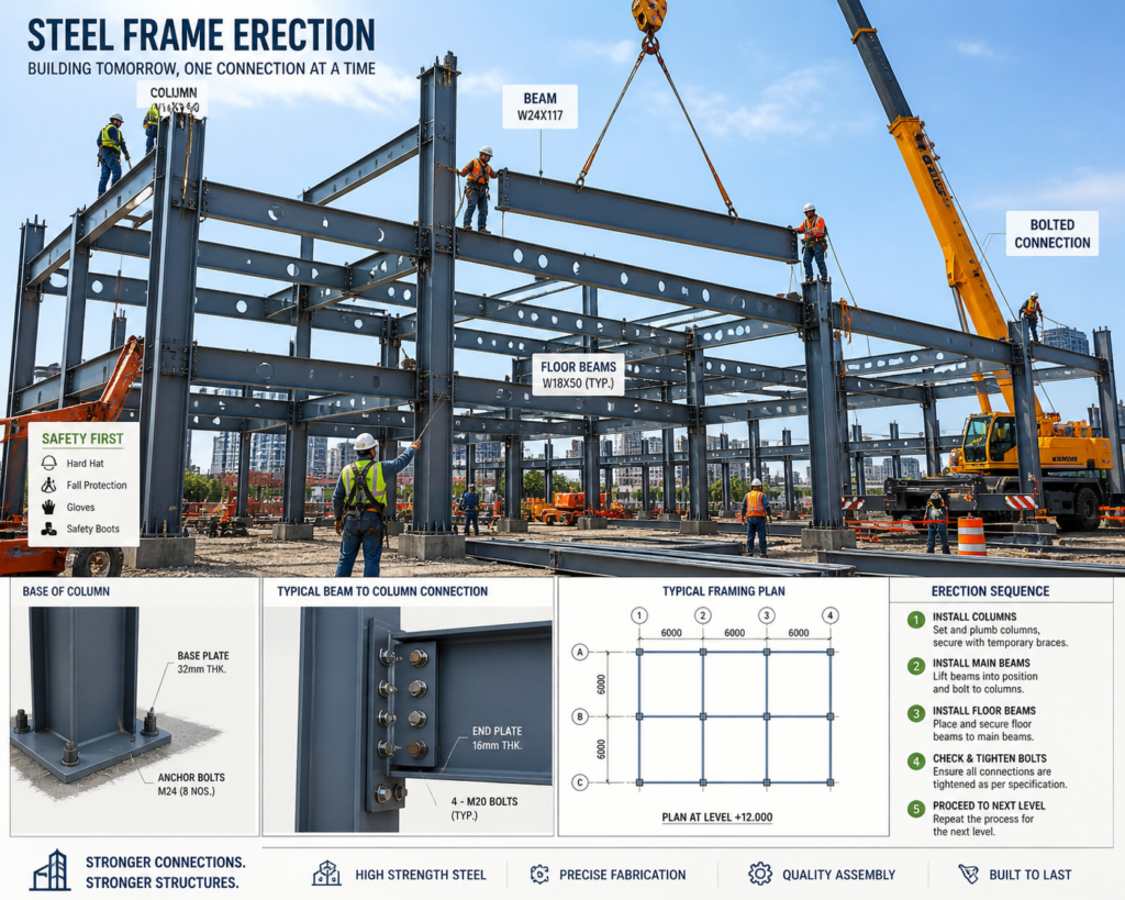
Structural and Safety Problems
Will this part break? How much load can this structure carry before it yields? How long will this component last under repeated loading? These are structural integrity questions that mechanical engineers answer through a combination of calculation, simulation, and physical testing. Structural failure in industries like aerospace, nuclear, and medical devices can have fatal consequences, so this work carries enormous responsibility.
Energy and Efficiency Problems
How can this engine extract more work from the fuel it consumes? How can we reduce the heat losses in this industrial process? What is the most efficient way to cool this high-power electronics assembly? These are thermodynamic and energy efficiency challenges. With energy costs rising and sustainability targets becoming increasingly stringent, improving energy efficiency is one of the most commercially valuable things a mechanical engineer can do.
Motion and Control Problems
How can we make this robotic arm move more accurately? What is causing the vibration in this rotating machine? How should we design the suspension system for this vehicle to maximise ride comfort and handling? These are dynamics, vibration, and control problems that require a deep understanding of kinematics, dynamics, and often control theory.
Manufacturing and Cost Problems
How can we reduce the cost to manufacture this component by 20 percent without compromising performance? Can we redesign this assembly to eliminate two fasteners and reduce assembly time? These are design for manufacture and design for assembly challenges. Engineers who can identify cost reduction opportunities without sacrificing quality or reliability create direct commercial value for their employers.
Reliability and Durability Problems
Why did this pump fail after only 6 months of service when it was designed to last 10 years? What is causing the fatigue cracks in this weld? Root cause analysis and reliability engineering are specialised but highly valued skills within mechanical engineering, particularly in industries where unplanned equipment downtime is expensive.
Key Insight: The best mechanical engineers are not just technically skilled. They are disciplined problem solvers who can define a problem clearly, select the most appropriate analytical approach, interpret results critically, and communicate their findings and recommendations in plain language.
Industries and Work Environments
Where a mechanical engineer works shapes everything about their day-to-day experience, the problems they encounter, the tools they use, and the culture of their workplace.
| Industry | Work Environment | Typical Focus Areas |
| Automotive | Open-plan design offices, test tracks, assembly plants | Powertrain, chassis, NVH, safety systems, electrification |
| Aerospace and Defence | Secure facilities, clean rooms, test hangars | Structural analysis, propulsion, thermal management, reliability |
| Energy (Oil, Gas, Renewables) | Offices, offshore platforms, wind farms, refineries | Pressure systems, rotating machinery, pipeline integrity, turbines |
| Manufacturing | Factory floors, process labs, quality labs | Process optimisation, tooling, lean manufacturing, automation |
| Medical Devices | Regulated cleanroom environments, R&D labs | Precision mechanisms, biocompatibility, miniaturisation, regulatory compliance |
| Robotics and Automation | Engineering offices, lab environments, customer sites | Robot design, actuator selection, motion control, systems integration |
| HVAC and Building Services | Offices, construction sites, mechanical plant rooms | Heat transfer, fluid systems, energy performance, commissioning |
| Consumer Products | Design studios, prototype workshops, supply chain facilities | Ergonomics, aesthetics, DFM, cost reduction, reliability |
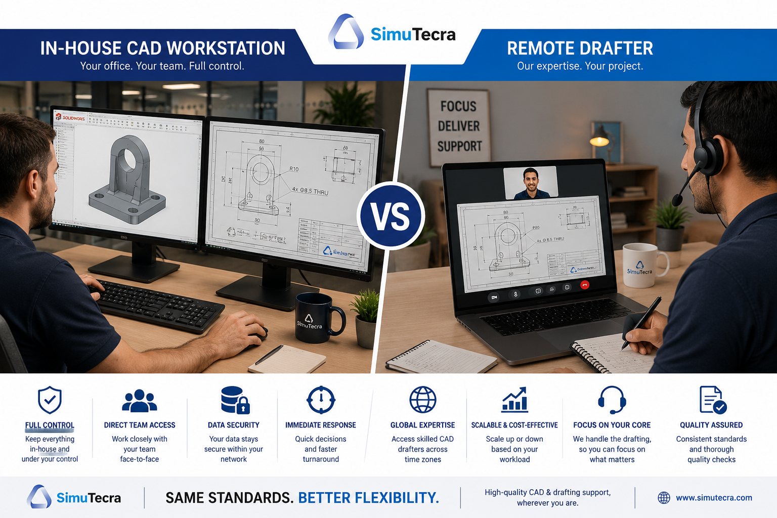
It is also worth noting that remote and hybrid work has become significantly more common for mechanical engineers involved in design, analysis, and documentation work. However, roles with strong manufacturing, field service, or laboratory components continue to require significant on-site presence.
Skills a Mechanical Engineer Needs
The skills required in mechanical engineering can be divided into technical competencies, software proficiency, and professional or soft skills. All three matter, and the balance between them shifts as an engineer progresses in their career.
Core Technical Competencies
- Solid understanding of statics, dynamics, and mechanics of materials
- Proficiency in thermodynamics and heat transfer principles
- Working knowledge of fluid mechanics
- Understanding of manufacturing processes and design for manufacturability
- Ability to read, create, and interpret engineering drawings and GD&T (Geometric Dimensioning and Tolerancing)
- Familiarity with material science and materials selection methods
Software Proficiency
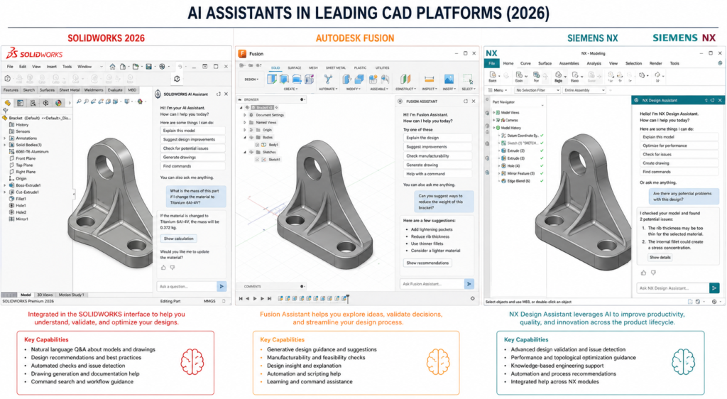
- 3D CAD modelling: SolidWorks, CATIA, NX, or Fusion 360
- 2D drafting: AutoCAD or equivalent
- FEA and simulation: ANSYS, SolidWorks Simulation, or COMSOL
- Mathematical and data analysis: MATLAB, Python, or Excel
- PDM / PLM systems: Teamcenter, Windchill, or equivalent
Professional and Interpersonal Skills
- Clear and precise written and verbal communication
- Structured analytical problem-solving and critical thinking
- Project management and time management under deadline pressure
- Ability to collaborate effectively with cross-functional teams
- Willingness to ask questions, challenge assumptions, and escalate concerns appropriately
- Attention to detail and a methodical approach to checking work
One skill that consistently separates high-performing mechanical engineers from average ones is the ability to translate between abstract technical concepts and practical real-world implications. An engineer who can explain to a non-engineer exactly why a design choice matters, and what the consequence of not addressing it would be, is immensely valuable to any organisation.
What a Typical Week Looks Like at Different Career Levels
The experience of being a mechanical engineer changes substantially as a career develops. Here is an honest picture of what a typical week might look like at three different career stages.
Junior Mechanical Engineer (0 to 3 Years Experience)
- Spending the majority of time on detailed CAD modelling and drawing updates directed by a senior engineer
- Running defined analysis tasks using templates or methods established by more experienced colleagues
- Attending design reviews as a listener and contributor, learning how senior engineers defend design decisions
- Preparing test documentation and supporting physical testing activities
- Responding to supplier and manufacturing queries about drawing tolerances and specifications
- Working through formal graduate development programs where applicable
At this stage, the primary goal is developing technical depth and learning how the team and company operate. Speed and independent decision-making develop gradually with experience.
Mid-Level Mechanical Engineer (3 to 8 Years Experience)
- Leading the design of discrete systems or subsystems within a larger product
- Running and interpreting FEA and simulation independently, making engineering judgements about results
- Owning specific technical areas within a project and presenting findings in design reviews
- Mentoring junior engineers on technical methods, drawing standards, and company processes
- Working more directly with suppliers to resolve technical issues and negotiate specification changes
- Beginning to manage small projects or workstreams, balancing technical work with some project coordination
At this stage, engineers are expected to work largely independently on technical tasks and to start developing the judgement to know when to escalate a problem versus when to resolve it within their own authority.
Senior or Principal Mechanical Engineer (8+ Years Experience)
- Setting the technical direction for major programs or product lines
- Making high-stakes engineering decisions and taking accountability for technical outcomes
- Representing the engineering team in customer, supplier, and executive-level meetings
- Developing and enforcing technical standards and best practices across the team
- Leading root cause investigations of significant field failures or customer complaints
- Identifying technology gaps and driving investment in new tools, methods, and capabilities
Senior engineers are defined by their judgement as much as their technical skills. They are expected to see around corners, anticipate problems before they occur, and provide steady technical leadership under pressure.
How the Role Has Changed with Modern Technology
The job of a mechanical engineer today looks considerably different from the same role 20 or even 10 years ago. Three technological shifts have had the most significant impact.
CAD and Simulation Have Replaced the Drawing Board
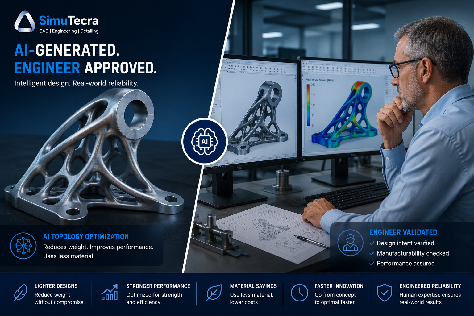
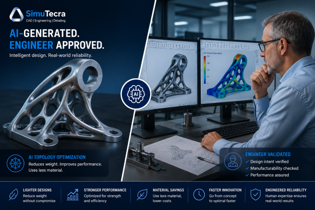
The transition from hand drafting to CAD was complete well before the turn of the millennium, but the capabilities of modern CAD and simulation tools continue to expand rapidly. Parametric modelling, generative design, cloud-based collaboration, and integrated simulation mean that engineers can explore far more design options in far less time than previous generations could.
Additive Manufacturing Has Changed What Is Possible
Industrial 3D printing, particularly metal additive manufacturing, has removed many of the geometric constraints that traditionally limited what a mechanical engineer could design. Components that were previously impossible or prohibitively expensive to machine can now be printed directly. This has opened up entirely new design languages, particularly in aerospace and medical devices.
Data, Sensors, and Digital Twins Are Creating New Engineering Work
Modern mechanical systems are increasingly instrumented with sensors that generate continuous streams of operational data. Mechanical engineers are now expected to understand how to use that data, whether for condition monitoring, predictive maintenance, performance optimisation, or regulatory compliance reporting. Digital twin technology, which creates a live virtual model of a physical asset updated by real-world sensor data, is becoming standard practice in industries like energy, aerospace, and advanced manufacturing.
Sustainability and Circular Economy Considerations Are Now Standard
The engineering profession is increasingly expected to design with the full environmental lifecycle of a product in mind. Life cycle assessment, material efficiency, repairability by design, and end-of-life recyclability are no longer niche specialisms; they are becoming standard requirements in product development processes across most major industries.
Mechanical Engineer vs. Other Engineering Roles
| Aspect | Mechanical Engineer | Civil Engineer | Electrical Engineer |
| Primary Domain | Machines, energy systems, thermal, fluid, and mechanical systems | Structures, infrastructure, geotechnics, water | Circuits, power systems, electronics, signals |
| Daily Tools | CAD (SolidWorks, CATIA), FEA (ANSYS), MATLAB | AutoCAD Civil 3D, structural analysis software, GIS | Circuit design tools, PCB software, signal analysers |
| Typical Outputs | 3D CAD models, engineering drawings, test reports, FEA results | Structural drawings, site plans, geotechnical reports | Circuit schematics, firmware, wiring diagrams |
| Team Collaboration | Manufacturing, quality, procurement, project management | Architects, surveyors, construction contractors | Software engineers, PCB designers, systems engineers |
| Physical Product? | Almost always: engines, robots, turbines, consumer goods | Always: bridges, roads, buildings, dams | Often: PCBs, motors, power infrastructure |
It is also increasingly common to find mechanical engineers in roles that overlap with software, data science, and electrical engineering, particularly in the automotive, robotics, and energy storage sectors. The boundaries of the discipline are genuinely blurring, and engineers who can work fluently across traditional disciplinary lines command a significant premium in the job market.
Frequently Asked Questions (FAQ)
What does a mechanical engineer do on a daily basis?
On a typical day, a mechanical engineer might work in CAD software to create or modify designs, run structural or thermal simulations to validate a design, attend design review or project meetings, communicate with suppliers about material or manufacturing specifications, review test data from physical prototypes, and prepare technical documentation. The exact mix of activities depends heavily on the engineer’s role, seniority, and industry.
What type of problems do mechanical engineers solve?
Mechanical engineers solve physical and engineering problems related to structures, machines, energy systems, and fluid flow. Common problems include ensuring components are strong enough to survive their operating loads, improving the energy efficiency of engines or thermal systems, diagnosing the cause of product failures, reducing manufacturing costs through design improvements, and developing new mechanisms or automated systems to perform specific tasks.
Is mechanical engineering mostly desk work or hands-on?
It depends on the specific role. Design, analysis, and R&D engineers spend the majority of their time at a computer working with CAD, simulation, and documentation tools. Manufacturing engineers, field service engineers, and test engineers spend significant time on the shop floor, in test facilities, or at customer sites. Most mechanical engineers experience both environments at some point in their career, and many find that the mix of desk work and physical work is one of the things they enjoy most about the profession.
What industry pays mechanical engineers the most?
In most countries, the highest-paying industries for mechanical engineers are aerospace and defence, oil and gas, semiconductor capital equipment, and medical devices. These sectors demand high precision, involve significant regulatory compliance overhead, and carry high consequences for failure, all of which push engineering salaries higher. Specialisations in areas such as FEA, CFD, and mechatronics also command salary premiums across industries.
What skills do I need to become a mechanical engineer?
The core technical skills required include solid mechanics, thermodynamics, fluid mechanics, and manufacturing process knowledge, typically built through a recognised university degree program. Proficiency with at least one major CAD platform and one simulation tool is expected in most roles. Equally important are problem-solving ability, clear technical communication, attention to detail, and the capacity to work collaboratively in cross-functional teams.
Can a mechanical engineer work in the software or technology industry?
Yes, and increasingly so. Mechanical engineers are hired in technology companies to work on hardware products, robotic systems, thermal management of electronics, and electromechanical systems. Engineers who develop Python or MATLAB programming skills alongside their mechanical knowledge are particularly well-positioned for roles in robotics, autonomous systems, digital simulation, and engineering software development.
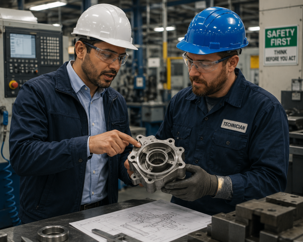
What is the difference between a mechanical engineer and a mechanical technician?
A mechanical engineer is a professional trained to design, analyse, and develop mechanical systems, typically holding a university degree and taking responsibility for engineering decisions and technical outputs. A mechanical technician, by contrast, typically has a trade qualification or diploma and focuses on installation, maintenance, repair, and operation of mechanical equipment. Engineers tend to work earlier in the design and development process, while technicians work closer to the physical hardware in production, maintenance, and field service contexts.
Conclusion
The question ‘what does a mechanical engineer do?’ has no single short answer, and that is precisely what makes the profession so compelling. Mechanical engineers design the devices that improve lives, build the machines that power industries, and solve the physical problems that stand between a concept and a commercially successful product.
Whether they are running stress simulations at a computer, testing a prototype on a rig, troubleshooting a field failure at a customer site, or collaborating with a cross-functional team to bring a new product to market, mechanical engineers are fundamentally problem solvers working at the intersection of science, creativity, and practical constraint.
If this guide has given you a clearer picture of the role, the next step is to explore the specific tools, techniques, and specialisations that define the profession in practice. On this site, you will find in-depth tutorials and guides on the software, analytical methods, and career strategies that working mechanical engineers use every day.
Ready to go deeper? Start with our pillar guide What Is Mechanical Engineering?, or explore our AutoCAD Tutorials for Beginners and Professionals to begin building the CAD skills that every mechanical engineer needs.