| 25-30% of total construction budget is MEP systems on a typical commercial building (CadCrowd, 2026) 30-40% of site rework in building projects caused by MEP clashes discovered after construction begins (Gsource, 2026) 10x ROI reported on a $200,000 VDC coordination effort delivering $2.55 million in rework and schedule savings (Construction Placements, 2026) $47B projected US MEP services market by 2031, growing at 6.33% CAGR from $32.55 billion in 2025 (Mordor Intelligence) |
Introduction: Why MEP Coordination Is the Most Expensive Problem in Construction
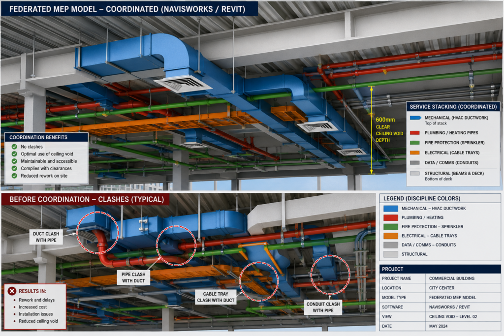
Inside the ceiling void of a commercial building, five or more different engineering systems share a space that might be 600mm deep. HVAC ductwork. Chilled water pipework. Sprinkler mains. Electrical cable trays. Data containment. Drainage. They all need to coexist, all need to be accessible for maintenance, and all need to avoid the structural frame that fills the same space.
When the teams designing each of those systems do not coordinate properly, the results show up on site as clashes: a duct running directly into a beam, a pipe conflicting with a cable tray, a VAV box with no service access because a riser was installed in front of it. Fixing those problems after installation costs far more than avoiding them in the drawing office. According to published construction industry research, MEP clashes account for 30 to 40 percent of all site rework on building projects.
This guide explains how MEP drafting works, what each discipline produces, how the coordination process resolves conflicts before they reach the site, and how BIM (Building Information Modeling) tools have transformed what is possible in terms of clash detection and drawing accuracy. If you are an engineer, a project manager, a main contractor, or a client trying to understand what the MEP coordination process is supposed to deliver, this is the guide you need.
| Quick definition: MEP drafting is the process of creating technical drawings and models for the mechanical (HVAC), electrical (power and lighting), and plumbing (water and drainage) systems within a building. MEP coordination is the process of combining those discipline drawings into a single model and resolving conflicts before construction begins, typically using BIM tools like Revit and Navisworks. |
What Is MEP? The Three Disciplines and What They Cover
MEP stands for Mechanical, Electrical, and Plumbing. These three letters represent the engineering systems that make a building work. Not the structure that holds it up, and not the architecture that makes it look a certain way, but the systems that heat, cool, power, light, supply water to, drain, and protect the occupants inside.
On larger projects, MEP expands to MEPF (adding Fire Protection) or MEPFP, and sometimes includes Low Voltage systems covering building management, security, and communications. The coordination challenge is the same regardless of how many disciplines are involved: all of these systems share the same physical building space and must be designed together, not separately.
| Discipline | What It Covers | Key Drawing Types |
| Mechanical (M) | HVAC: air handling units, ductwork, VAV boxes, exhaust fans, chillers, cooling towers, boilers, thermal insulation | Ductwork layouts, equipment schedules, riser diagrams, section details, air terminal schedules |
| Electrical (E) | Power distribution, lighting, cable trays, conduit routes, switchgear, UPS, emergency power, fire alarm, data/comms | Single-line diagrams, lighting layouts, cable tray routing, earthing layouts, load schedules |
| Plumbing (P) | Domestic hot and cold water, drainage, sanitary waste, roof drainage, gas supply, medical gases in healthcare | Pipe routing plans, isometrics, drainage layouts, sanitary riser diagrams, fixture schedules |
| Fire Protection (FP) | Sprinkler systems, fire mains, hydrant networks, suppression systems, smoke extract | Sprinkler layouts, hydraulic calculation zones, smoke control diagrams |
| Low Voltage (LV) | Building management systems, security, access control, CCTV, AV, voice and data | Containment routes, BMS point schedules, network topology diagrams |
Why MEP Systems Are So Difficult to Coordinate
Each MEP discipline has its own engineers, its own design tools, its own drawing conventions, and its own technical constraints. An HVAC engineer sizes ductwork based on airflow calculations and designs routes based on equipment locations and zone requirements. An electrical engineer designs cable routes based on load distribution and switchgear locations. A plumbing engineer designs pipework based on fixture locations, gravity drainage requirements, and water pressure calculations.
None of these engineers is primarily thinking about what the other disciplines need. The result, without a structured coordination process, is a set of designs that each work perfectly on paper but physically cannot all fit in the same building at the same time. The ceiling void that HVAC needs for a 800mm high duct is the same void that electrical needs for two layers of cable tray and that plumbing needs for a 150mm drainage pipe with a 1 in 80 fall.
Structural steel complicates this further. Beams go where loads require them to go, not where MEP routes are conveniently planned. Without early coordination, MEP services end up routed around structural members in ways that add length, reduce efficiency, compromise building height, and cost significantly more to install than a properly coordinated design would.
The MEP Drafting Process: From Brief to Coordinated Drawing Package
Understanding the MEP drafting process in sequence helps every member of the project team understand what is supposed to happen at each stage and what information is needed from others before their work can progress. Here is the complete workflow from project brief through to a clash-free coordinated drawing package.
Stage 1: Concept and Schematic Design
At the earliest design stage, MEP engineers work from the architect’s concept to establish the system strategy. What type of heating and cooling system will the building use? Where will the main plant rooms be located? How will vertical risers be distributed through the floor plan? How will incoming electrical supply enter the building and route to distribution boards?
The outputs at this stage are schematic diagrams, not detailed drawings. A schematic HVAC layout identifies the system type and main equipment. A single-line electrical diagram shows the supply route and main distribution hierarchy. These are not yet MEP coordination drawings. They are the engineering decisions that will drive everything that comes after them.
Stage 2: Design Development and Technical Calculations
As the architectural design firms up, MEP engineers run their technical calculations. HVAC engineers calculate heating and cooling loads room by room using thermal modelling software. They size air handling units, select chillers and boilers, and calculate ductwork cross-sections based on airflow velocities. Electrical engineers calculate connected and demand loads, select switchgear ratings, and size cable runs. Plumbing engineers size water supply pipes based on simultaneous demand and design drainage systems with the correct gradients.
The outputs of this stage are the technical specifications and equipment schedules that drive the detailed layout drawings. Without these calculations, layout drawings are guesswork. The size of a duct is not arbitrary. It is the result of an airflow calculation that determines what cross-section is needed to deliver the required cubic metres per hour at the correct velocity for the application.
Stage 3: Detailed Layout Drafting
With technical parameters established, the detailed MEP layout drawings can be produced. In a BIM environment, this means each discipline builds their system in 3D within a platform like Revit MEP or MagiCAD. Every duct segment has a cross-section. Every pipe has a diameter. Every cable tray has a width and depth. Every equipment item is modelled at the correct physical dimensions.
In a 2D CAD environment, this means annotated plan drawings for each floor level and each discipline, showing service routes, equipment locations, and connections with dimensions and specification callouts. 2D CAD-based MEP drafting is still common on smaller projects and in markets where BIM adoption is less advanced, but it produces a significantly higher coordination risk because clashes between disciplines cannot be detected automatically.
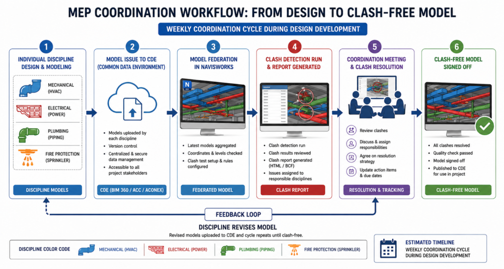
Stage 4: Model Federation and Clash Detection
Once each discipline has produced their detailed model or drawings, the coordination process begins. In a BIM workflow, the discipline models are uploaded to a Common Data Environment and federated in a coordination platform such as Navisworks. The federated model contains all disciplines simultaneously: structure, architecture, mechanical, electrical, plumbing, and fire protection layered together in a single 3D view.
Clash detection software then automatically identifies every location where elements from different discipline models conflict. The clash report categorises conflicts by type, severity, and discipline combination. The coordination team reviews the report, prioritises the critical clashes, and convenes a coordination meeting with representatives from each affected trade to agree on who moves what.
| How clash detection changed everything: Before BIM-based clash detection, coordination relied on engineers from different disciplines overlaying their drawings manually on a drawing board or a CAD screen and looking for conflicts. On a complex project with hundreds of drawings, this process was slow, expensive, and fundamentally incomplete. Software-based clash detection finds every geometric conflict in a model in seconds, producing a prioritised report that a human review process would take weeks to achieve. |
Stage 5: Coordination Meetings and Clash Resolution
The clash report does not resolve itself. Each clash requires an engineering decision: which service moves, by how much, and in which direction? The coordination meeting is where those decisions are made, typically with the lead MEP engineer chairing and representatives from each affected discipline attending.
Weekly coordination cycles are standard on active projects during design development. Each week, the disciplines update their models based on the previous meeting’s resolutions, re-issue to the CDE, the federation is updated, and a new clash run is performed. The number of outstanding clashes should decrease each cycle until a clash-free status is achieved.
In practice, achieving zero hard clashes is realistic. Achieving zero soft clashes is typically not, because some soft clash rules are conservative and the actual installation can accommodate tighter clearances than the rule specifies. The goal is to resolve all critical hard clashes and all soft clashes in areas where service access or installation sequence would be compromised.
Stage 6: Coordinated Drawing Production
With a clash-free or clash-minimised model, coordinated drawings can be produced directly from the 3D model. Floor plan layouts, section views through congested areas, riser diagrams, and spool drawings for prefabrication are all derived from the coordinated geometry rather than drafted independently. This is where BIM delivers one of its highest-value outputs: the drawing and the model are always consistent because one is generated from the other.
Types of Clashes in MEP Coordination and How Each Is Resolved
Not all clashes are equal. MEP clash detection identifies conflicts in several categories, each with different implications for how urgently they need to be resolved and what the resolution options are.
| Clash Type | Definition | Common MEP Examples |
| Hard clash | Two objects physically occupy the same space | HVAC duct running through a structural beam; sprinkler pipe through electrical panel |
| Soft clash | Objects are within a defined clearance zone of each other | Electrical cable tray within 100mm of fire sprinkler main; VAV box within 200mm of beam soffit |
| Workflow clash | Timing or sequencing conflict between trades | Electrical conduit installed before plumbing sleeve, blocking pipe route; equipment needing access panels that are walled off |
| Tolerance clash | Cumulative dimensional errors within acceptable individual tolerances | Three adjacent services each within tolerance but together exceeding available ceiling void space |
The Real Cost of Late Clash Discovery
Published data on MEP rework consistently shows that the cost of resolving a clash increases by an order of magnitude at each stage of the construction process. A clash resolved in the design coordination model costs the time of an engineer and a revision to a drawing. The same clash discovered during installation requires dismantling what is already installed, redesigning the route, procuring new materials, and reinstalling. On complex projects, a single late-discovered clash in a congested riser can cost tens of thousands and delay multiple trades that were waiting for that riser to be complete.
The published case study data is striking. A $200,000 investment in Virtual Design and Construction coordination on one referenced project delivered $2.55 million in rework and schedule savings, a return on investment of more than ten to one. These are not theoretical figures. They are documented outcomes from structured BIM MEP coordination programs on real construction projects.
MEP Service Routing Priority: Who Moves When There Is a Conflict
One of the most practically useful things an MEP coordinator or project engineer can know is the routing priority hierarchy. When two services conflict and one must move, the decision about which one gives way is not arbitrary. It follows a physical logic based on the routing flexibility of each service type.
| Priority | Service Type | Why It Has Priority | Routing Flexibility |
| 1 | Gravity drainage and sewage | Cannot change gradient without redesign | Very low. Fixed slope dictates route. |
| 2 | Large HVAC ductwork | Large cross-section, difficult to reroute | Low. Major re-routes require load recalculation. |
| 3 | Pressurised chilled water and heating pipework | Can use bends and rises but costly to reroute | Medium. Fittings add cost but direction is flexible. |
| 4 | Electrical cable trays | Flexible, can change direction easily | High. Small section, many routing options. |
| 5 | Electrical conduit and cables | Most flexible service on site | Very high. Can be rerouted with minimal cost. |
Gravity Drainage: The Immovable Starting Point
Gravity drainage is the service with the least routing flexibility of all MEP systems and therefore takes absolute priority in space allocation. A drainage pipe must fall continuously from the point of use to the point of discharge at the required gradient. Typically 1 in 80 for branch drains and steeper for shorter runs. You cannot add bends to a gravity drainage pipe without either raising the starting point or dropping the discharge point, both of which may be impossible given the floor-to-floor height and the slab structure.
This is why drainage routes must be established first in the coordination process, before other services claim the ceiling void space that the drainage gradient requires. On projects with tight floor-to-floor heights, drainage routing is often the determining factor in whether certain ceiling heights are achievable at all.
Large Ductwork: The Second Immovable Constraint
HVAC ductwork, particularly main trunk ducts feeding large air handling systems, comes second in the priority hierarchy. A duct serving a 10,000 square metre open-plan floor might be 800mm wide and 400mm deep. It cannot be reduced in cross-section without increasing air velocity beyond the noise and efficiency limits. It cannot be routed around structural members without increasing fan power and potentially redesigning the entire distribution system.
Ductwork also changes cross-section as it branches. The main trunk duct is the largest. First-order branches are smaller. Final room terminals are smallest. The coordination drawing must show this reduction in cross-section accurately because it determines the clearances available for other services at each point along the route.
| Practical coordination rule: Always ask the HVAC engineer to model their ductwork first in any zone where ceiling height is constrained. Everything else coordinates around the ductwork and drainage. Trying to fit ductwork around already-placed electrical and plumbing services almost always requires rework from all disciplines. |
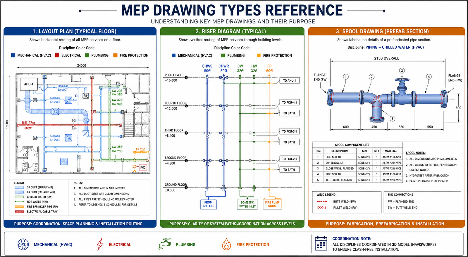
MEP Drawing Types: What Each Drawing Communicates and Who Uses It
A complete MEP drawing package contains multiple types of drawings, each serving a specific purpose in the construction and operation of the building. Understanding what each drawing type communicates prevents the common problem of contractors using the wrong drawing for the wrong purpose.

| Drawing Type | What It Shows | Who Uses It |
| Layout plan | Plan view of MEP system routes at each floor level | Design consultants, contractors, building control |
| Riser diagram | Vertical representation of pipe or duct routing through floors | Coordination team, commissioning engineers |
| Single-line diagram | Simplified electrical system showing circuit relationships | Electrical engineers, building control, FM teams |
| Section drawing | Cut-through view showing services stacked in a corridor or ceiling void | Coordination team to verify spatial fit |
| Isometric drawing | 3D representation of pipe runs for fabrication | Plumbing and mechanical fabricators |
| Spool drawing | Fabrication drawing for a specific prefabricated section | Offsite prefabrication workshops |
| Equipment schedule | Data table for each equipment item: model, capacity, connections | Procurement, commissioning, FM teams |
| Coordination drawing | Combined overlay of all MEP disciplines in one view | Main contractor, all MEP subcontractors |
| As-built drawing | Final record of installed positions after construction | FM teams, future maintenance, decommissioning |
Spool Drawings and the Prefabrication Advantage
Spool drawings are among the most valuable outputs of a well-executed BIM coordination process. A spool is a prefabricated section of pipework or ductwork, assembled in a controlled workshop environment and delivered to site ready to connect. Spool drawings specify every dimension, every fitting, every weld or flange, and every connection point for that prefabricated section.
The advantage of prefabrication is significant. Workshop fabrication is faster, produces higher-quality welds and connections, requires less site safety management, and removes trade congestion from a busy site during critical installation windows. But it only works if the drawings are accurate and the model was clash-free when the spools were generated. A spool fabricated from a pre-coordination model is a spool that may not fit when it arrives on site.
This is why the sequence matters: coordination complete first, spool drawings issued after. On projects where this sequence is violated, either because of schedule pressure or inadequate coordination process management, the result is fabricated sections that require modification on site, eliminating most of the cost and time advantage that prefabrication was meant to deliver.
MEP Drafting and Coordination Software: What Teams Actually Use
The MEP software landscape in 2026 is dominated by the Autodesk platform for most global markets, with specialist tools serving specific disciplines and project types. Understanding which tool does what helps project managers set realistic expectations about workflow and deliverables.
| Software | Developer | Primary Use | MEP Discipline Strength | BIM Level |
| Autodesk Revit MEP | Autodesk | Full BIM MEP modeling | Mech, Elec, Plumbing | Level 2+ |
| AutoCAD MEP | Autodesk | 2D/3D MEP drafting | All disciplines | Level 1 |
| Navisworks | Autodesk | Clash detection, federation | All (coordination tool) | Level 2+ |
| MagiCAD | Progman | MEP modeling in Revit/CAD | Strong mechanical and HVAC | Level 2 |
| Bentley OpenMEP | Bentley | MEP design in OpenBuildings | All disciplines | Level 2+ |
| Trimble MEP | Trimble | Fabrication and field | Mechanical, plumbing | Fabrication |
| Dialux / Relux | Various | Lighting design / calculation | Electrical (lighting) | Specialist |
| IES VE | IES | Building energy simulation | Mechanical (HVAC loads) | Specialist |
| AutoCAD Electrical | Autodesk | Electrical panel and wiring | Electrical schematics | Level 1 |
Revit MEP: The BIM Coordination Standard
Autodesk Revit MEP is the most widely adopted BIM platform for MEP drafting globally. Its discipline-specific worksets allow mechanical, electrical, and plumbing engineers to work within the same project file simultaneously, with each discipline’s work visible to others in real time. Equipment families carry full technical data: a VAV box in Revit knows its airflow rate, its connection size, its service zone, and its maintenance access requirement.
The integration between Revit and Navisworks for clash detection is the most common coordination pipeline in UK, US, European, and Australian markets. Revit produces the discipline models. Navisworks federates them, runs clash detection, and generates the clash report. The coordination team resolves clashes, engineers update the Revit models, and the cycle repeats.
Navisworks: The Coordination Engine
Navisworks is not a modeling tool. It is a coordination and review platform that reads models from virtually any 3D software platform and federates them into a single review environment. Its ClashDetective module runs automated clash detection against user-defined rules, producing clash reports that can be sorted by discipline pair, clash type, and severity.
The practical advantage of Navisworks is its format agnosticism. A project where the architect models in ArchiCAD, the structural engineer in Tekla, and the MEP team in Revit can still be federated in Navisworks because all three platforms export to NWC or IFC format that Navisworks reads. Navisworks is the coordination tool that works regardless of what each discipline used to build their model.
8 MEP Coordination Mistakes That Cause Expensive On-Site Problems
The majority of MEP coordination failures on site trace back to a small number of process failures that are well understood and entirely preventable. These are the mistakes that experienced MEP coordinators see repeatedly, and they are the ones that account for the majority of the rework costs documented in published construction industry research.
| Mistake | What Goes Wrong On Site | How to Prevent It |
| No coordination meeting before modeling | Each discipline drafts in isolation, clashes not found until federation | Run a pre-design coordination meeting. Agree corridor zones, ceiling void allocation, and riser routes before any trade starts modeling. |
| Missing clearance zones in clash rules | Soft clashes ignored, services too close to maintain | Define clearance rules in Navisworks before the first clash run. 100mm minimum from electrical to fire main is a standard starting rule. |
| Outdated model versions in federation | Clash detection run on stale geometry, clashes missed | Enforce CDE version control. Never federate models older than the agreed issue cycle, typically weekly. |
| Structural model not included | MEP routes through beams discovered on site | Always include the structural model in the federated coordination model. Structural clashes are the most expensive to fix on site. |
| LOD mismatch between disciplines | One trade models at LOD 200, another at LOD 350. False soft clashes appear. | Agree LOD expectations per discipline per RIBA stage before modeling begins. Document in the BEP. |
| No priority hierarchy for routing | Lower-priority services occupy prime routes, pushing high-priority services into awkward paths | Establish routing priority: gravity drainage first, then ductwork, then pressurised pipework, then cable trays and conduit. |
| As-built drawings not updated | FM teams have no record of where services run. Maintenance causes costly disruption. | Make as-built model update a contractual delivery requirement with a practical completion check. |
| Spool drawings issued before coordination complete | Prefabricated sections do not fit because model was not yet clash-free | Lock spool drawing issue until coordination sign-off is complete for the relevant zone. |
The most expensive single mistake in MEP coordination: Issuing spool drawings for prefabrication before the clash detection process is complete for the relevant zone. On one documented project, prefabricated pipework sections totalling GBP 340,000 required on-site modification because spool drawings were issued three weeks before the coordination model for that floor was signed off. The modification cost exceeded the original fabrication saving.
BIM and AI in MEP Coordination: What Is Actually Changing in 2026
The relationship between BIM MEP coordination and artificial intelligence in 2026 is moving from early adoption to practical implementation across the MEP sector. The improvements are not theoretical. They are showing up in reduced coordination meeting times, faster clash resolution cycles, and more reliable spool drawing production.
AI-Assisted Clash Prioritisation
One of the most time-consuming aspects of MEP coordination has always been reviewing clash reports that contain thousands of individual conflicts, many of which are low-priority soft clashes or duplicate detections of the same fundamental routing problem. AI tools are beginning to prioritise clash reports automatically: grouping related clashes that share a common root cause, flagging critical structural clashes for immediate escalation, and filtering out soft clashes that fall within acceptable installation tolerance.
This reduces the time coordination teams spend in clash review meetings significantly. One project team using AI-assisted clash review reported completing weekly coordination cycles in 40 percent of the time compared to manual clash report review, because the AI filtering removed approximately two-thirds of the reported clashes that required no engineering decision.
Generative Design for MEP Routing
Generative design tools are beginning to be applied to MEP service routing problems, particularly in constrained ceiling void conditions. Given the structural model, the architectural model, the service routing priority hierarchy, and the spatial constraints of the ceiling void, generative design algorithms can propose multiple valid routing configurations that avoid hard clashes before any human engineer begins the layout.
This does not remove the engineer from the process. It provides a starting point that is already clash-free with the structure and the architectural envelope, allowing the coordination team to focus on inter-service coordination rather than spending time avoiding the structural frame manually. On high-density projects with multiple competing services in constrained ceiling voids, this starting point advantage is measurably valuable.
Digital Twins and Operational MEP Management
The fully coordinated BIM model that is produced at the end of a successful MEP coordination process is increasingly being maintained as a digital twin through the building’s operational life. Sensor data from installed equipment, maintenance records, energy consumption logs, and inspection reports are connected to the building model so that facilities management teams have a continuously updated picture of system status.
For MEP systems, the digital twin enables predictive maintenance based on equipment performance data, energy optimisation by comparing actual versus modelled consumption, and renovation planning using the as-built model rather than attempting to survey hidden services. The condition precedent for all of these benefits is that the as-built MEP model was delivered accurately at project completion, which requires the same coordination discipline that produces a clash-free construction model in the first place.
AI for MEP Documentation
The documentation layer of MEP projects, producing equipment schedules, operation and maintenance manuals, commissioning records, and handover packages, is one of the most time-consuming aspects of project delivery and one of the areas where AI tools are delivering immediate practical benefit. Structured data extracted from a coordinated BIM model can be processed by AI tools to generate formatted O and M manuals, equipment registers, and maintenance schedules in a fraction of the time required for manual preparation.
For MEP engineers and project managers using tools like Claude for documentation assistance, the combination of structured BIM data output and AI-driven document generation produces handover packages that are both faster to produce and more complete than manually compiled equivalents. The technical content comes from the model. The communication layer comes from AI.
Real-World Example: MEP Coordination on a Commercial Office Building
To make the coordination process concrete, here is how it plays out on a typical commercial office development: ten floors, 2,500 square metres per floor, mixed open-plan and cellular office layout with a central core containing lifts, toilets, and risers.
The Coordination Challenge
The typical floor-to-floor height is 4.0 metres. The structural concrete flat slab is 300mm deep. The raised access floor adds 150mm. The finished ceiling sits at 2.7 metres above finished floor level. That leaves a ceiling void of 4,000 minus 300 minus 150 minus 2,700 = 850mm in which to fit all MEP services.
In that 850mm, the team needs to route: primary HVAC supply ductwork at 500mm x 200mm, chilled water pipework at 150mm diameter plus insulation, primary drainage at 100mm diameter with a 1 in 80 fall, electrical cable trays at 600mm wide and 100mm deep, sprinkler mains at 100mm diameter, and data containment at 200mm wide. Without coordination, these services will not all fit. They need to be stacked and sequenced, with priority given to drainage and ductwork, and the remaining services fitted around them.
The Coordination Outcome
After four weekly coordination cycles on a project of this type, a well-managed BIM coordination process resolves the vast majority of hard clashes and produces a coordinated ceiling void arrangement that is signed off by all disciplines. The outputs include a set of coordinated floor plans and ceiling sections for each typical floor, a fully resolved riser diagram, spool drawings for the prefabricated pipework sections, and an agreed installation sequence for each zone that allows trades to work without blocking each other.
The value of this output is not just avoiding the on-site clashes. It is the confidence that the contractors installing each system know exactly where their services run, where they connect, and in what sequence. That certainty drives faster installation, more reliable programme adherence, and a significantly smoother commissioning process where systems can be tested as designed because they were installed as coordinated.
Conclusion: MEP Coordination Is Not a Task. It Is a Project-Level Commitment.
The statistics on MEP rework, 30 to 40 percent of site rework caused by coordination failures, ten-to-one ROI on structured coordination programs, are not abstract numbers. They are the documented outcome of a choice that every project team makes: either invest in coordination during design, or pay a significantly higher price for the same problems during construction.
A well-executed MEP drafting and coordination process does not guarantee a perfect project. But it systematically eliminates the category of problems that are most expensive to fix on site, most disruptive to programme, and most damaging to relationships between contractors who are trying to work in the same physical space at the same time.
In 2026, BIM MEP coordination using Revit and Navisworks is the established standard on any commercial, healthcare, education, or mixed-use project above a certain scale. AI tools are beginning to accelerate the clash review process, improve routing proposals, and automate the documentation that sits around the coordination work. The fundamentals, model each discipline accurately, federate regularly, resolve hard clashes before they reach site, and issue coordinated drawings for construction, have not changed and will not change.
Understand the process. Enforce the sequence. Demand the deliverables. The building performance and the project budget both depend on it.
A clash found in a coordination model costs minutes. The same clash found on site costs weeks.
Frequently Asked Questions
What is MEP drafting?
MEP drafting is the process of creating technical drawings and models for the mechanical, electrical, and plumbing systems within a building or infrastructure project. These drawings communicate the layout, routing, sizing, and specifications of HVAC systems, power distribution, lighting, water supply, drainage, and fire protection to contractors, engineers, and building managers who will install and operate those systems.
What is MEP coordination and why does it matter?
MEP coordination is the process of integrating the individual mechanical, electrical, plumbing, structural, and architectural models into a single federated model and resolving spatial conflicts before construction begins. It matters because all MEP services share the same ceiling voids, vertical risers, and plant rooms. Without coordination, services clash on site and rework can consume 30 to 40 percent of MEP site labour hours according to published construction industry research.
What is the difference between a hard clash and a soft clash in MEP?
A hard clash occurs when two building elements physically occupy the same space. For example, an HVAC duct routed directly through a structural beam. A soft clash occurs when two elements are within a defined clearance zone of each other without touching, for example an electrical cable tray within 100mm of a fire sprinkler main. Hard clashes are always critical. Soft clashes require engineering judgment about whether the clearance is sufficient for installation, operation, and maintenance access.
What software is used for MEP drafting and coordination?
The most widely used software for MEP drafting and coordination in 2026 is Autodesk Revit MEP for BIM-based 3D modeling and Autodesk Navisworks for clash detection and model federation. AutoCAD MEP handles 2D drafting workflows. MagiCAD adds specialist MEP capabilities within Revit. Trimble supports prefabrication and field installation. Specialist tools include Dialux for lighting design and IES VE for HVAC load calculations.
What is a spool drawing in MEP?
A spool drawing is a fabrication drawing for a specific prefabricated section of pipework or ductwork. It shows the exact dimensions, material specifications, connection types, and weld or flange positions for a section that will be fabricated off-site and installed as a complete unit. Spool drawings are generated from the coordinated BIM model after clash detection is complete, so the fabricated section is guaranteed to fit when it arrives on site.
How does AI improve MEP drafting and coordination workflows?
AI is improving MEP workflows in 2026 in four practical ways. AI-assisted clash prioritisation ranks detected clashes by severity automatically, reducing the time coordination teams spend reviewing low-impact soft clashes. Generative design tools explore optimal routing paths for ductwork and pipework given the spatial constraints of a ceiling void. Automated drawing production generates 2D drawings directly from the coordinated 3D model. And natural language tools allow project managers to query the BIM model and receive MEP status reports without needing to navigate the model directly.
buildingSMART International — IFC and OpenBIM Standards for MEP Coordination
Leave a Reply