The question most engineering managers ask when considering 3D scanning for reverse engineering is not whether it produces better geometry. Most engineers accept that answer without much debate. The real question is whether it justifies the investment: the capital cost of the scanner, the software license, the training time, and the ongoing operational overhead. Does all of that add up to a lower total cost than having a skilled engineer measure the part and model it by hand?
The honest answer: it depends on part complexity, project volume, quality requirements, and whether you are building in-house capability or using a service bureau. For simple prismatic parts at low volumes, manual modeling is often cheaper. For complex organic geometry, worn legacy parts, large variant families, or regulated applications requiring measurement traceability, scan-to-CAD is typically both faster and cheaper in total cost, and qualitatively superior.
This article builds the cost model that makes that decision quantitative rather than intuitive. It maps every cost element of both approaches, builds seven scenario-specific comparisons with realistic hour and dollar estimates, identifies the crossover point at which scanning becomes economically dominant, and provides a breakeven calculator for in-house scanner investment.
What Manual Modeling Actually Costs: The Full Picture
Manual modeling for reverse engineering is deceptively simple to estimate at the surface level: an engineer measures a part and builds a CAD model. The visible cost is the engineer’s time. But the full cost includes several elements consistently overlooked in informal comparisons, producing estimates significantly lower than reality.
The Measurement Phase: More Time Than It Looks
Manual measurement of a complex mechanical part is not quick. A simple prismatic bracket with ten defined features might take 30 to 60 minutes to measure thoroughly with calipers, depth gauges, and a surface plate. A complex casting with curved surfaces, multiple angled features, and critical bore-to-bore relationships might take 4 to 8 hours of careful measurement, often requiring CMM time for spatial relationships handheld tools cannot capture reliably.
Engineers consistently underestimate measurement time for two reasons. First, the initial pass captures obvious dimensions, and subsequent CAD modeling reveals dimensions that were not initially measured, creating back-and-forth between physical part and CAD that adds 20 to 50 percent to total measurement time. Second, complex geometry requires multiple fixture setups to reach features from different orientations.
The Modeling Phase: Where Complexity Multiplies Cost
For a simple prismatic part, an experienced engineer might spend 2 to 4 hours in CAD. For a complex casting with organic geometry, rib structures, and multiple angled bosses, the same engineer might spend 20 to 40 hours, because complex geometry requires reasoning about design intent behind every measurement: which surfaces are nominally flat, which radii are standard nominal values, which surfaces are true freeform curves? Getting this wrong produces a model reproducing worn or imprecise geometry rather than original design intent.
The Hidden Cost of Manual Measurement Errors
The most significant hidden cost in manual modeling is the error rework cycle. Manual measurement introduces errors at every step: misreading a caliper, misidentifying the datum surface, transposing a recorded value. These errors propagate into the CAD model and are typically not discovered until the model is used to manufacture a part that does not fit.
The rework cost when an error reaches manufacturing includes the incorrectly manufactured part (material, machining time, setup), the schedule delay while the error is diagnosed, and potentially production downtime costs. For a machined part with a three-day lead time, a measurement error adds three to five days to the project timeline plus the full cost of the first-off part, typically $500 to $5,000 depending on material and complexity.
Manual Modeling True Cost FormulaTotal manual cost = Measurement time + CAD modeling time + Quality check time + (Error probability x Expected rework cost). The error probability and rework cost are consistently omitted from informal comparisons. For complex parts with many interrelated dimensions, a 20 to 30 percent error rate requiring significant rework is not unusual. Including probability-weighted rework typically increases true manual modeling cost by 25 to 50 percent over a best-case estimate.
What Scan-to-CAD Actually Costs: Beyond the Scanner Price Tag
The most common objection to scan-to-CAD investment is the capital cost. This is real, typically $15,000 to $80,000 for a quality structured light system, plus $3,000 to $12,000 per year for reconstruction software. But focusing on capital cost in isolation misrepresents the economics, because this cost is amortized across every part the system processes over its operational life.
Amortizing the Capital Cost
A structured light scanning system has a practical operational life of 5 to 8 years with regular calibration. Divided over 5 years, a $40,000 scanner costs $8,000 per year in capital amortization. At 100 parts per year the scanner adds $80 of capital cost per part. At 400 parts per year, it adds $20. These numbers are negligible relative to engineer labor cost for any part of moderate complexity.
Software at $6,000 to $8,000 per year adds $15 to $80 per part at the same volumes. Consumables add approximately $5 to $20 per part. Total non-labor overhead per part ranges from $40 at high volume to $180 at low volume, both well within the labor savings for anything beyond the simplest parts.
Scan-to-CAD Labor: Where the Real Savings Appear
The scan capture phase typically takes 0.5 to 2 hours for a medium-sized industrial part across 6 to 15 scan positions. This compares to 1 to 8 hours of manual measurement for the same part, with the scan capturing more complete geometry without back-to-the-part re-measurement cycles.
The reconstruction phase using scan-guided CAD modeling in tools like Geomagic Design X is genuinely faster than equivalent manual parametric modeling for complex geometry. For simple prismatic parts, the time saving is small. For complex castings and organic forms, scan-guided reconstruction can be 50 to 70 percent faster than equivalent manual modeling because the engineer is tracing known geometry rather than reasoning about unmeasured surfaces.
Quality Verification: The Comprehensive Advantage
Deviation analysis, comparing the reconstructed CAD model against the original scan data, takes 1 to 3 hours for a thorough review. This has no direct equivalent in manual modeling, where verification typically means re-measuring a subset of critical dimensions. The scan verification is more comprehensive: it checks every surface simultaneously, rather than a spot-check of selected features.
This also provides a downstream asset: the scan data serves as a permanent archive of the physical geometry at the time of scanning. If questions arise months later, the scan data can be re-examined without physical access to the original part. Manual modeling produces no equivalent record.
Complete Cost Breakdown: Every Element Side by Side
The following table maps every significant cost element of both approaches with realistic ranges. All labor costs assume $100 to $150 per hour, reflecting mid-range senior engineering costs in most North American and European markets.
Scan checks entire surface; manual checks selected dimensions only
Rework risk
High – errors propagate silently to model
Low – errors visible immediately in deviation map
Manual errors typically found only at first-off manufacturing
Error rework cost (when occurs)
4-20 hrs (re-measure, re-model affected sections)
1-4 hrs (re-examine scan data, update model)
Scan data archived; no physical part access needed for re-check
Documentation package
Engineer notes only – minimal audit trail
Scan + deviation report = full traceable audit trail
Critical difference for aerospace, medical, and regulated applications
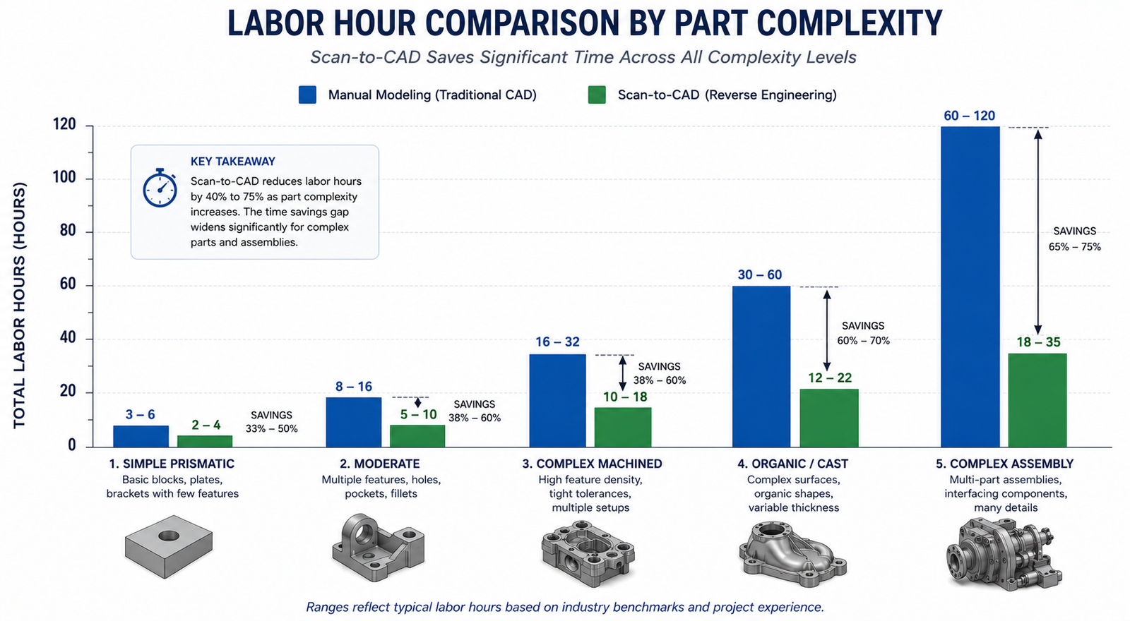
The key observation: the two approaches have similar per-part costs for simple parts but diverge dramatically as complexity increases. The scan approach’s labor time scales more slowly with complexity because the scanner captures full geometry regardless of how complex the part is, while manual measurement time scales nearly linearly with geometric complexity.
The following seven scenarios cover the range of reverse engineering situations engineering teams typically encounter, from the simplest part where manual modeling wins to the complex assembly where scanning wins decisively.
Scenario
Complexity
Manual Total
Scan-to-CAD Total
Cost Winner
Quality Winner
Simple prismatic bracket, well-documented
Low
$450-$900
$600-$1,200 (incl. scanner amortization)
Manual
Tie
Complex organic component, no drawings
High
$3,000-$9,000 (high error risk)
$1,500-$3,500
Scan-to-CAD (2-3x cheaper)
Scan-to-CAD
Worn legacy part, design intent uncertain
Med-High
$2,000-$6,000 + rework risk
$1,200-$2,500
Scan-to-CAD clearly
Scan-to-CAD
Precision machined part, H7/H6 fits
Medium
$900-$2,400
$1,400-$2,800 (CMM hybrid needed)
Tie or Manual
CMM hybrid
Family of 10 size variants
Med x10
$4,500-$9,000
$2,000-$4,000 (scan one, table for variants)
Scan-to-CAD strongly
Scan-to-CAD
Single one-off, simple geometry
Low
$300-$600
$800-$1,500 (overhead dominates)
Manual
Tie
Assembly of 15 interacting parts
High
$15,000-$45,000
$5,000-$12,000
Scan-to-CAD (3-4x cheaper)
Scan-to-CAD
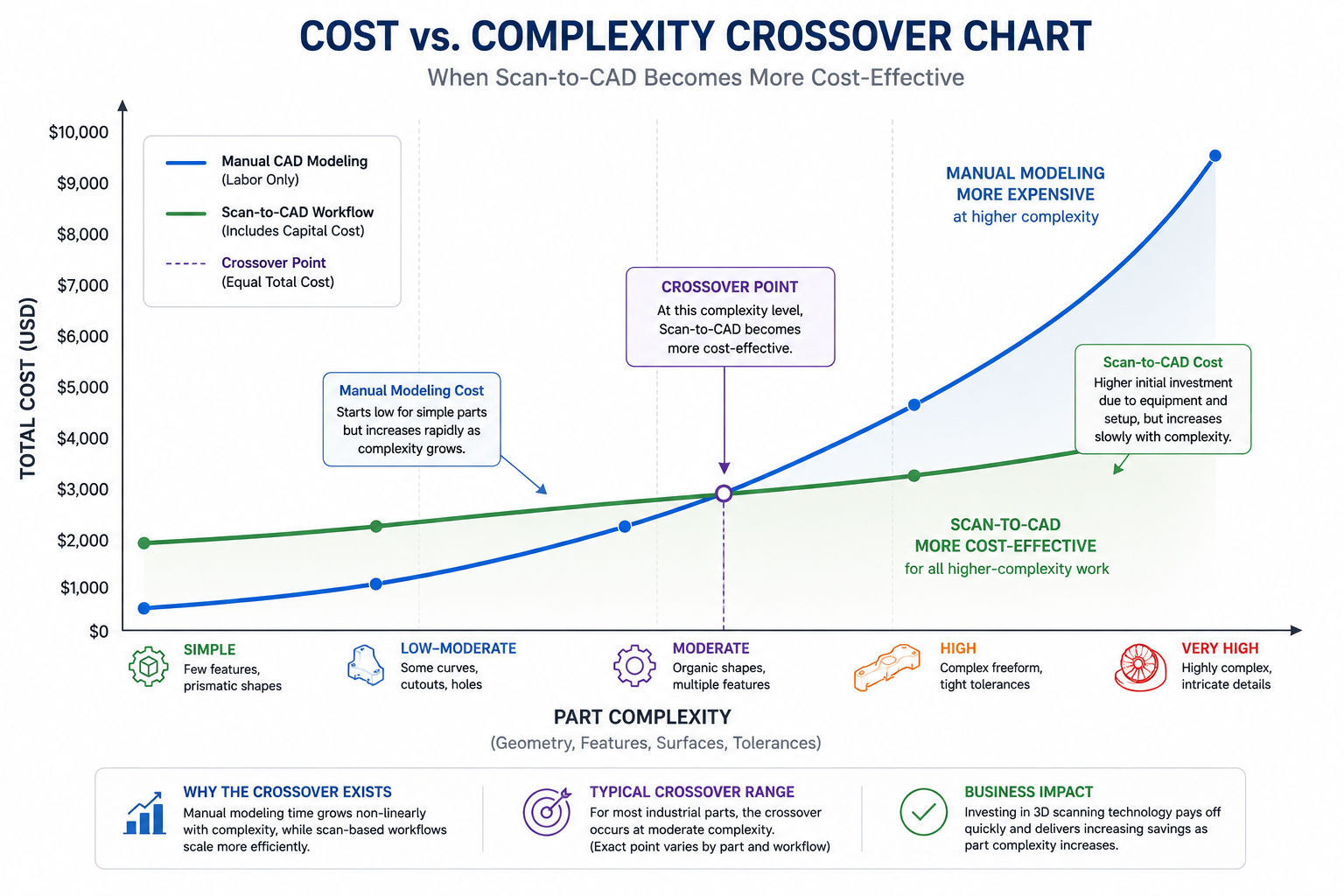
The most important pattern: for simple single parts, manual wins on cost. From moderate complexity onward, and for any scenario involving multiple related parts, scan-to-CAD wins because labor savings compound while capital cost per part decreases with volume. The quality column is consistent: scanning wins for virtually every scenario beyond the simplest, because deviation analysis verifies the entire model comprehensively.
The Crossover Point: When Does Scanning Pay Off?
The crossover is a function of three variables: part complexity (determines per-part labor saving), project volume (determines capital cost amortization per part), and quality requirements (determines whether scan verification’s comprehensive documentation has additional financial value).
Complexity-Based Crossover
At 50 parts per year, scanning becomes cost-competitive at moderate complexity: roughly 20 to 50 geometric features and several organic surfaces, corresponding to approximately 10 to 20 hours of manual modeling time per part. Parts below this threshold are generally cheaper to model manually. Parts above it are almost always cheaper with scanning, often dramatically so for the most complex cases.
Volume-Based Crossover
At constant moderate complexity, each part generates roughly $500 to $1,000 in labor savings from scan-assisted modeling at $125 per hour. A $40,000 scanner with $8,000 per year software has a total annual cost of $16,000. At $750 per part average savings, the annual breakeven volume is 21 parts per year, fewer than two parts per month. This is achievable for any organization doing regular reverse engineering work. Above this volume, every additional part generates pure financial benefit.
Quality Requirement Crossover
For regulated industries, the crossover improves further because the scan verification report is a compliance asset with quantifiable financial value that reduces regulatory risk and supports quality management system audits. Including the avoided cost of alternative CMM inspection programs significantly improves scanning economics even for simpler parts in these contexts.
The Breakeven Calculator: Building Your Own Business Case
The following framework provides a structured calculation for determining the financial return on investment from a scan-to-CAD program. Adapt the numbers to your actual labor rates, scanner quotation, and part mix.
Scan-to-CAD ROI Calculator Framework
INPUTS (replace with your actual values):

  Engineer labor rate (fully loaded):         $125 / hr
  Scanner capital cost (5yr amortization):    $40,000 / 5yr = $8,000/yr
  Scan software license (annual):             $7,000 / yr
  Consumables + calibration (annual):         $1,500 / yr
  Training investment (amortized over 5yr):   $3,000 / 5yr = $600/yr

  Total annual scanning overhead:             $17,100 / yr

PER-PART ANALYSIS (adjust for your part mix):

  Average manual modeling hours per part:     18 hrs
  Average scan-to-CAD hours per part:         9 hrs
  Hours saved per part:                       9 hrs
  Labor cost saved per part:                  9 x $125 = $1,125
  Rework cost avoided (15% rate, 6hr avg):    0.15 x 6 x $125 = $112
  Total value per part:                       $1,237

BREAKEVEN VOLUME:
  Breakeven = Annual overhead / Value per part
            = $17,100 / $1,237
            = 13.8 parts/yr (round to 14)

ROI AT VARIOUS VOLUMES:
   20 parts/yr:  ($1,237 x 20)  - $17,100 =   $7,640 net annual benefit
   50 parts/yr:  ($1,237 x 50)  - $17,100 =  $44,750 net annual benefit
  100 parts/yr:  ($1,237 x 100) - $17,100 = $106,600 net annual benefit

SENSITIVITY: Simpler parts (8hr manual / 6hr scan, 2hr saving)?
  Value per part: 2hr x $125 + $112 rework avoided = $362
  Breakeven: $17,100 / $362 = 47 parts/yr (still achievable for most teams)
The most important sensitivity is the average complexity of your part mix. Teams primarily dealing with complex parts find this calculation strongly favorable even at modest volumes. Teams primarily dealing with simple prismatic parts find the breakeven higher and may be better served by accessing scanning as a service for the minority of parts that justify it.
In-House Scanning vs. Scanning as a Service
For organizations with lower volumes or highly variable project requirements, accessing 3D scanning as a service from specialist bureaus provides the quality benefits of scanning without capital investment. Understanding when each model makes sense is as important as understanding when scanning makes sense at all.
The Service Bureau Model
3D scanning service bureaus typically charge $150 to $500 per part for scan capture and mesh delivery, or $800 to $3,000 per part including full parametric reconstruction, depending on complexity and turnaround. At these rates, service bureau scanning is cost-effective for organizations doing fewer than 10 to 15 scan projects per year, or for organizations with occasional high-complexity parts within a general part mix too simple to amortize in-house equipment.
When In-House Investment Is Clearly Better
In-house scanning is the better economic choice when: the annual part volume exceeds the breakeven (typically 15 to 50 parts per year depending on complexity), when turnaround time is critical to operations, when parts are sensitive or proprietary and cannot leave the facility, or when the organization wants to develop internal scanning capability as a strategic asset. The hybrid model works well for many organizations: in-house for the majority of parts, service bureau for occasional projects requiring specialized technology.
Quality-Adjusted Cost: The Dimension Pure Cost Analysis Misses
A cost comparison looking only at labor hours and capital costs misses a genuinely important dimension: quality-adjusted cost, which accounts for the value of the quality difference between the two approaches and the cost implications of that difference over the part’s operational life.
The Verification Coverage Difference
Manual modeling produces a CAD model with spot-checked quality assurance where a subset of dimensions have been verified against the physical part. Scan-to-CAD produces a model with comprehensive surface verification through deviation analysis: every surface compared against measurement data simultaneously, rather than a spot-check of selected features.
For a replacement part that must function correctly in production equipment, a part manufactured from a spot-checked manual model carries higher residual risk of fit and function failure than one from a scan-verified model. If that residual risk materializes, the cost of the failure can easily exceed the entire cost of the original reverse engineering program.
The Documentation Value in Regulated Environments
In regulated industries, the scan data and deviation analysis report are valuable engineering documents supporting regulatory compliance, quality management system audits, and litigation defense. A manual modeling process produces essentially no documentation of the measurement process. A scan-to-CAD process produces a complete traceable chain of evidence that can be reproduced and audited years later. For pharmaceutical equipment, medical devices, aerospace components, and other regulated products, this traceability is a financial asset that reduces regulatory risk and audit response costs.
Frequently Asked Questions
Q: Is scan-to-CAD faster than manual modeling?
For complex parts, yes, significantly. For simple prismatic parts, the difference is small or nonexistent and manual modeling may be marginally faster. The time advantage grows with complexity because the scanner captures complete geometry regardless of how complex the part is, while manual measurement time scales nearly linearly. For a complex casting taking 30 to 60 hours to measure and model manually, scan-guided reconstruction typically takes 10 to 22 hours, a two to three times reduction. For a simple bracket taking 4 hours manually, scanning saves roughly 1 hour, not enough to justify scanner capital cost on a single part.
In-house structured light scanning equipment costs $15,000 to $80,000 for the scanner, plus $3,000 to $12,000 per year for professional reconstruction software. Amortized over 5 years at 50 to 100 parts per year, non-labor overhead per part is approximately $100 to $350. Scanning as a service costs $150 to $500 per part for scan capture and mesh delivery, or $800 to $3,000 per part including full parametric reconstruction, depending on complexity and turnaround requirements.
Q: What is the breakeven volume for investing in a 3D scanner for reverse engineering?
For a mid-range structured light scanner ($40,000) with professional reconstruction software ($7,000 per year) applied to moderately complex parts (15 to 20 hours manual modeling time), the typical breakeven volume is 14 to 25 parts per year. At 50 parts per year, a typical in-house scanning program generates $40,000 to $80,000 of net annual benefit beyond equipment cost.
Q: When should I use manual modeling instead of scan-to-CAD?
Manual modeling is the better choice when: the part is simple and prismatic with fewer than 10 hours of expected modeling time, project volume is too low to amortize scanner investment and service bureau pricing would exceed the manual labor cost, the part has a surviving original drawing providing complete dimensional information, or critical features are threads and precision bores requiring CMM hybrid measurement regardless of scanning approach.
Q: Does 3D scanning produce better CAD models than manual modeling?
For complex geometry, yes. Scan-to-CAD models are dimensionally referenced against comprehensive scan data throughout reconstruction, and the completed model is verified against scan data through deviation analysis. This produces a model with documented, verifiable accuracy across every surface. Manual modeling produces a model with spot-checked accuracy on selected dimensions. For simple prismatic parts, the quality difference is smaller, but the documentation advantage of scan-to-CAD remains significant for regulated applications.
Q: How do I calculate the ROI of a 3D scanner for my engineering team?
Calculate average manual modeling hours per part (measurement plus CAD plus verification plus estimated rework). Calculate expected scan-to-CAD hours per part. Multiply the difference by your fully loaded engineer labor rate to get value per part. Divide total annual scanner cost (amortized capital plus software plus consumables plus training) by value per part to get breakeven volume. If projected annual part volume exceeds breakeven, the investment is financially justified. Also include the quality value of comprehensive scan verification if your application is in a regulated industry.
Conclusion:
The cost comparison resolves into a clear framework once all relevant cost elements are accounted for. For simple parts at low volumes, manual modeling is typically cheaper because scanner overhead is not recovered from modest labor savings on straightforward geometry. For complex parts, high volumes, families of related parts, or applications with quality documentation requirements, scan-to-CAD is typically both cheaper in total cost and better in quality.
The two insights that most change how engineering managers approach this decision: first, manual modeling’s true cost includes error rework risk that is frequently omitted from informal comparisons. Second, the scan verification report is a financial asset, not just a technical product, because it reduces regulatory risk, supports quality management system audits, and provides a permanent archive proving the CAD model was correctly derived from the physical part.
Run the breakeven calculation with your own numbers. The breakeven volume for most organizations doing moderately complex reverse engineering falls at 15 to 25 parts per year, a threshold many engineering teams exceed in their first month of a serious RE program. The financial case is usually not as close as it appears before the full cost model is built.
Reverse engineering has quietly become standard practice across a far wider range of industries than most engineers realize. The image that comes to mind for most people, an aerospace engineer scanning a turbine blade or an automotive supplier benchmarking a competitor’s transmission, is accurate but represents only a fraction of where this technology now delivers value. From patient-specific orthopedic implants designed from CT scans of an individual’s anatomy, to wind farm operators scanning damaged turbine blades for repair, to museums digitizing fragile artifacts before they degrade further, reverse engineering has become a general-purpose tool for converting physical reality into usable digital design data.
What makes this article different from the lists of industries that appear elsewhere is the level of specificity. Every industry has different reasons for using reverse engineering, different accuracy requirements, different regulatory constraints, and different dominant scanning technologies. An aerospace engineer reverse engineering a structural bracket for a legacy aircraft operates under entirely different requirements than a museum conservator digitizing a sculpture, even though both processes start with a 3D scan and end with a digital model. Treating these as the same activity, as most overview content does, obscures the genuinely useful information: what does reverse engineering actually look like in your industry, specifically?
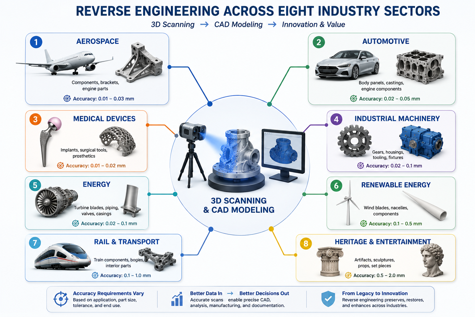
This article covers eight industry sectors where reverse engineering has become integral to operations, with the specific technical drivers, accuracy requirements, dominant technologies, and regulatory frameworks that define reverse engineering practice in each. It draws on the metrology framework and scanning technology knowledge covered in the rest of this series to explain not just that these industries use reverse engineering, but precisely how and why.
Industry Overview: Drivers, Accuracy, Technology, and Regulation
The table below summarizes the eight industries covered in this article, mapping each to its primary reverse engineering driver, typical accuracy requirement, dominant scanning technology, and the regulatory framework that governs the application. Use this as a quick reference, and refer to the detailed sections for the technical reasoning behind each entry.
Industry
Primary RE Driver
Typical Accuracy Need
Dominant Technology
Regulatory Framework
Aerospace & Defense
Legacy parts (DMSMS), OEM tooling loss
0.01 to 0.05 mm
Structured light + CMM hybrid, CT for internals
AS9100, MIL-SPEC config management
Automotive (OEM + Aftermarket)
Competitive benchmarking, legacy parts, EV development
0.02 to 0.10 mm
Structured light (ATOS), photogrammetry for large body panels
The pattern across this table reflects a consistent principle from earlier in this series: accuracy and technology requirements are driven by the application, not the industry label. Aerospace and medical devices both demand precision because of the consequences of failure, but the specific accuracy numbers and scanning technologies differ based on part geometry, material, and the specific decision the scan data will support.
1. Aerospace and Defense: Legacy Parts and DMSMS Management
Aerospace and defense represent the most mature application of reverse engineering, and the primary driver has a name that every aerospace sustainment engineer knows well: DMSMS, Diminishing Manufacturing Sources and Material Shortages. Military and commercial aircraft remain in service for 30 to 50 years or longer. The suppliers who originally manufactured specific components frequently go out of business, discontinue product lines, or lose the tooling and technical data needed to remanufacture a part long before the aircraft itself is retired.
When a part becomes unavailable through DMSMS, the operating organization faces a choice: ground the aircraft until an alternative is found, redesign the system to use a different component (an expensive and time-consuming engineering change that may require requalification), or reverse engineer the original part to enable manufacture from a new source. Reverse engineering is frequently the fastest and most cost-effective path, particularly for mechanical components, brackets, housings, and structural parts where the original design intent can be recovered reliably from the physical part.
The Aerospace Reverse Engineering Workflow
Aerospace reverse engineering follows the most rigorous version of the workflow covered earlier in this series, because the output must support airworthiness certification. The CAD model produced from the scan is not just a reference; it becomes the basis for a new technical data package that must demonstrate equivalence to the original part’s form, fit, and function. This means the deviation analysis step is not optional documentation, it is evidence submitted as part of the certification basis.
Structured light scanning combined with CMM probing for critical features is the dominant technology combination, consistent with the 10:1 measurement uncertainty ratio requirements for parts with tight tolerances. Industrial CT scanning is increasingly used for castings and complex internal geometry common in aerospace hydraulic and pneumatic components, where internal porosity assessment is also part of the material qualification process alongside geometric capture.
Configuration Management and Traceability
Every reverse engineered aerospace part must be traceable to its source data under AS9100 configuration management requirements. The scan data, the deviation analysis, the engineering judgment applied to distinguish design intent from wear (covered in detail in the previous article on scan-to-CAD challenges), and the resulting CAD model all become part of a permanent design record. This record must demonstrate that the new part is equivalent to the original in every dimension that affects form, fit, or function, with documented justification for any dimension that was idealized away from the as-scanned value.
The financial scale of this application is significant. A single grounded aircraft costs an operator tens of thousands of dollars per day in lost revenue or mission capability. A reverse engineering program that takes two weeks to produce a certified replacement part, versus a redesign and requalification process that could take a year, represents a direct and substantial cost avoidance that justifies the rigor of the aerospace reverse engineering process.
2. Automotive: Benchmarking, Legacy Parts, and EV Development
The automotive industry uses reverse engineering across three distinct applications that are often conflated in general discussions but involve different workflows and different stakeholders: competitive benchmarking, legacy and classic vehicle part reproduction, and electric vehicle development
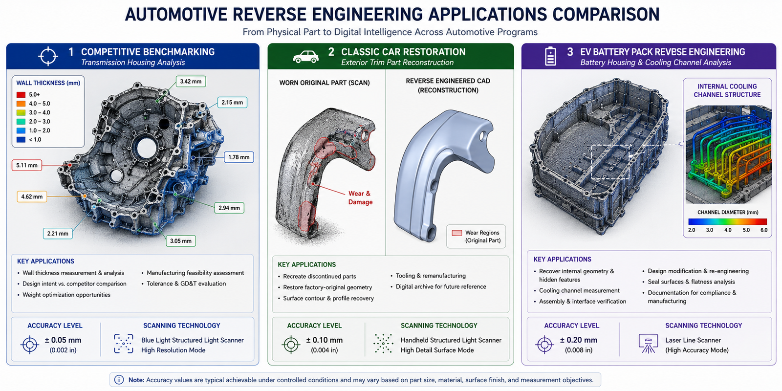
Competitive Benchmarking
Automotive OEMs and tier-one suppliers routinely purchase competitor vehicles, disassemble them, and scan key components to understand design approaches, manufacturing methods, and material specifications. This is a legitimate and widespread practice, and it sits squarely within the legal framework for reverse engineering covered in the previous article: studying a lawfully purchased product to understand the engineering approach used by a competitor, in order to inform the design of a non-infringing alternative or to benchmark performance, is broadly protected activity in most jurisdictions.
Benchmarking scans typically focus on weight reduction opportunities (scanning a competitor’s structural component to measure wall thicknesses and rib geometry that achieve a target stiffness at lower mass), packaging efficiency (understanding how a competitor fits more functionality into a smaller volume), and manufacturing process inference (analyzing surface finish, parting lines, and feature geometry to determine whether a part is cast, forged, or machined, and what tooling approach was used). Structured light scanning with ATOS-class systems is the standard technology, providing the 0.02 to 0.05mm accuracy needed to extract meaningful wall thickness and geometry data.
Legacy and Classic Vehicle Parts
The classic car restoration market has grown into a substantial reverse engineering application in its own right. Parts for vehicles that have been out of production for decades, trim pieces, brackets, interior components, and mechanical parts, are frequently unavailable from any source. Specialist reverse engineering shops scan original parts (often the only surviving examples, sometimes in worn or damaged condition) and produce CAD models suitable for small-batch manufacturing via CNC machining, investment casting, or 3D printing.
This application directly exercises the wear-versus-design-intent challenge covered in the previous article: a 60-year-old trim part has accumulated wear, corrosion, and possibly previous repair attempts, and the reverse engineering process must distinguish what the part looked like when new from what it looks like now. The accuracy requirements are generally more relaxed than aerospace (0.1 to 0.5mm is often adequate for non-structural trim and interior parts), but the design intent recovery judgment is just as demanding.
Electric Vehicle Development
EV development has created new reverse engineering applications specific to battery and drivetrain systems. Battery pack housings, with their complex internal structures for cell modules, cooling channels, and structural support, are frequently reverse engineered during competitive analysis to understand packaging density and thermal management approaches. Drivetrain components, particularly the housings for electric motors and reduction gearboxes, are reverse engineered to support both benchmarking and the increasingly common practice of localizing manufacturing of components originally designed by a different supplier or in a different region, requiring a complete CAD redefinition from physical parts when original design data is not transferable across the supply chain relationship.
3. Medical Devices and Orthopedics: Patient-Specific Design
Medical devices represent the most technically sophisticated application of reverse engineering in this entire list, because the most advanced use case, patient-specific implant design, inverts the traditional reverse engineering workflow. Instead of scanning an existing manufactured part to recreate its design, the scan captures a patient’s individual anatomy, and the CAD model produced is an entirely new design customized to that anatomy.
Patient-Specific Implants and Surgical Guides
Orthopedic reconstruction, particularly for complex fractures, tumor resections, and revision joint replacements, increasingly uses CT scanning of the patient’s affected anatomy as the input to a design process that produces a custom implant or surgical guide matched to that individual’s bone geometry. The CT scan captures both the external bone surface and, critically, the internal trabecular bone structure and any remaining healthy bone stock after a tumor resection or in a revision surgery where previous implant material must be accommodated.
The CAD reconstruction process for these applications often references the patient’s own anatomy on the contralateral (opposite) side of the body as a mirrored design reference, applying the symmetry analysis techniques covered in the previous article, but in this case the mirrored anatomy is the design target rather than a verification check. A custom cranial implant, for example, is designed to match the mirror image of the patient’s intact skull on the opposite side, reconstructed from the CT data and verified through deviation analysis against the mirrored geometry before the implant design proceeds to manufacturing.
Legacy Device Documentation and Sustaining Engineering
Medical device manufacturers also use reverse engineering for sustaining engineering on legacy products: devices that remain on the market or in clinical use but whose original CAD data has been lost, was created in CAD software no longer supported, or belongs to a component supplier relationship that has ended. ISO 13485 and FDA 21 CFR Part 820 quality system requirements mandate that manufacturers maintain design history files for devices they support, and reverse engineering is the mechanism for reconstructing this documentation when original records are incomplete.
This application carries particular weight because medical device design changes, even changes intended only to recreate existing approved geometry, may require regulatory notification or resubmission depending on the jurisdiction and the nature of the change. The reverse engineering documentation package, including the scan data, deviation analysis, and design rationale for any idealization decisions, becomes part of the regulatory submission supporting evidence that the recreated design is equivalent to the originally approved device.
Accuracy Requirements for Medical Applications
Accuracy requirements vary significantly within medical applications. External anatomical capture for surgical planning and visualization can tolerate 0.5 to 1mm accuracy. Implant interface surfaces, the regions where the implant contacts bone or articulates with another implant component, require 0.05 to 0.1mm accuracy to ensure proper fit and function. For legacy device component reverse engineering where the device has tight manufacturing tolerances (precision mechanisms in surgical instruments, for example), the same 10:1 measurement uncertainty principles from the metrology framework apply directly.
4. Industrial Machinery and Equipment: Keeping Production Running
For manufacturing plants operating equipment that may be decades old, reverse engineering has become the primary tool for maintaining production continuity when original equipment manufacturer support has ended. This is perhaps the broadest application by sheer volume of parts: every manufacturing plant with aging equipment has wear parts, custom brackets, gearbox components, and mechanical assemblies that periodically fail and need replacement, often from OEMs that no longer exist or no longer support the specific equipment generation.
The Wear Part Reproduction Cycle
Industrial machinery reverse engineering most commonly addresses wear parts: components subject to abrasion, impact, or cyclic loading that fail predictably over time. Conveyor system components, gearbox housings, pump impellers, and custom tooling for production lines are typical examples. Because these parts fail repeatedly, plants often build a digital inventory: reverse engineer the part once, store the CAD model, and manufacture replacements on demand without needing to reverse engineer the same part again.
The wear-versus-design-intent challenge is central to this application. The part being scanned is, by definition, often a worn or partially failed example, since the failure is what triggered the need for a replacement. Engineers must distinguish the original design geometry (what the part looked like when new and functioning correctly) from the accumulated wear pattern (the geometry change that led to the failure). Reproducing the worn geometry would simply create a replacement part that fails the same way.
Custom Tooling and Fixture Reproduction
Beyond wear parts, industrial reverse engineering frequently addresses custom tooling and fixtures: jigs, gauges, and production tooling that were designed in-house or by a contract toolmaker decades ago, with no surviving CAD data. When this tooling is damaged or when a plant needs to duplicate a fixture for a second production line, scanning the existing tooling and reconstructing a CAD model is typically faster and cheaper than redesigning the fixture from functional requirements alone, particularly when the existing tooling has been refined through years of production use to address practical issues that are not documented anywhere except in the tooling’s actual geometry.
5. Energy: Oil, Gas, and Power Generation
The energy sector, encompassing oil and gas production, refining, and conventional power generation, operates some of the longest-lived capital equipment of any industry. Power generation turbines, compressors, and large valve assemblies are designed for 30 to 50 year operational lifespans, and reverse engineering has become essential for maintaining this equipment as original manufacturer support diminishes over that timeframe.
Turbine Blade Reverse Engineering
Gas and steam turbine blades are among the most demanding reverse engineering applications in any industry because they combine extremely tight aerodynamic tolerances with complex freeform organic geometry and operate in conditions that cause measurable wear and erosion over their service life. The airfoil profile of a turbine blade directly determines its aerodynamic performance, and even small deviations from the design profile measurably affect efficiency.
Reverse engineering turbine blades for repair or replacement requires structured light scanning at 0.02 to 0.05mm accuracy combined with NURBS surface reconstruction techniques (covered in the reverse engineering workflow article) to capture the complex 3D airfoil twist and camber. The wear-versus-design-intent challenge is especially significant here: blades that have been in service show erosion at the leading edge and tip, and the reconstructed CAD model must represent the original design profile, not the eroded profile, for the blade to perform correctly after repair or replacement.
Valve Bodies, Pump Casings, and Pressure Vessel Components
Large valve bodies, pump casings, and pressure vessel nozzles in process plants are frequently reverse engineered when replacement parts are needed for equipment whose original manufacturer has been acquired, merged, or gone out of business. These components often have complex internal flow passages that benefit from industrial CT scanning when the internal geometry significantly affects flow performance, combined with external structured light or laser scanning for the overall envelope and mounting interfaces.
The regulatory context for these components involves pressure equipment standards (ASME Boiler and Pressure Vessel Code, API standards for oil and gas equipment) that govern material specifications, wall thickness requirements, and pressure ratings. Reverse engineering for pressure-retaining components must verify not just geometric accuracy but also confirm that wall thicknesses meet the pressure rating requirements for the service conditions, which may require the CT-based wall thickness measurement capability covered in the previous articles.
6. Renewable Energy: Wind Turbine Blade and Component Repair
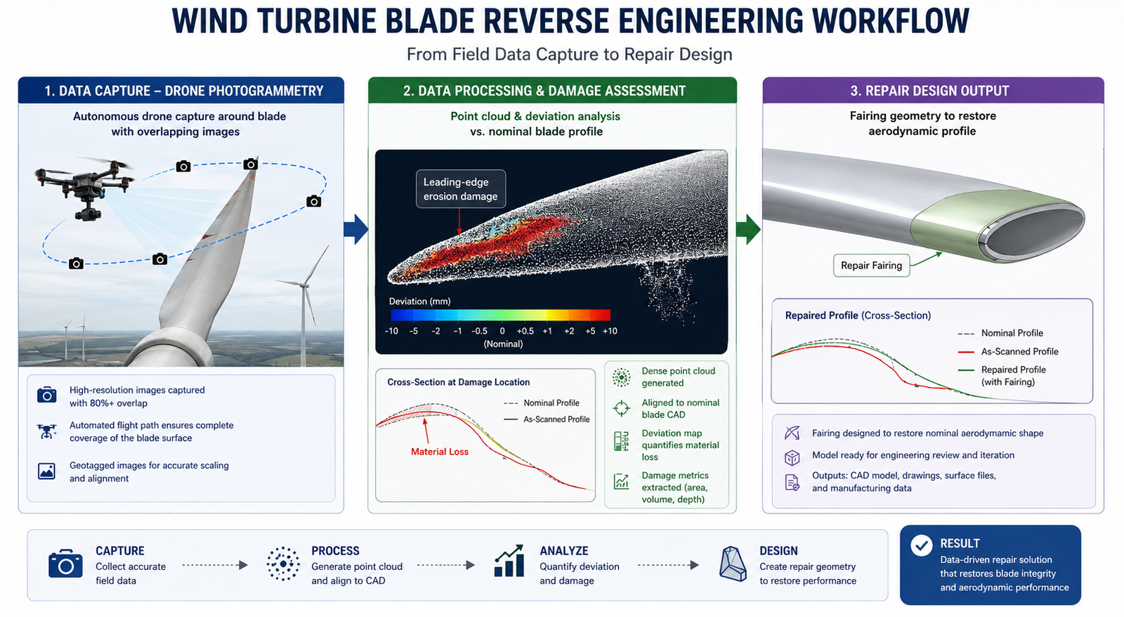
The renewable energy sector, particularly wind power, has become one of the fastest-growing applications of reverse engineering, driven by the simple economics of turbine fleet maintenance at scale. A utility-scale wind farm operator manages dozens to hundreds of turbines, each with blades that experience leading-edge erosion, lightning strike damage, and occasional structural damage from extreme weather events.
Blade Damage Assessment and Repair Design
When a wind turbine blade is damaged, whether from erosion, impact, or lightning strike, drone-based photogrammetry has become the standard technology for capturing the blade’s current geometry without requiring the turbine to be taken offline for a manual inspection that would require climbing or rope access. The drone flies a defined pattern around the blade, capturing overlapping photographs that are processed into a 3D model using the photogrammetry techniques covered earlier in this series.
The accuracy requirements for blade damage assessment are more relaxed than the metrology applications discussed elsewhere, typically 0.5 to 2mm is adequate, because the primary decisions being made are whether damage exceeds repair thresholds defined by the blade manufacturer’s maintenance manual, and what repair geometry (filler material extent, aerodynamic fairing shape) is needed to restore the blade profile. This is squarely in the category of application where, as discussed in the accuracy requirements article, the required accuracy should be matched to the engineering decision being made rather than defaulting to precision metrology standards.
Gearbox and Drivetrain Component Reverse Engineering
Wind turbine gearboxes and main bearing housings represent a higher-accuracy application within the renewable sector. These components have precision-toleranced interfaces (bearing bores, gear mounting faces) that require 0.05 to 0.2mm accuracy consistent with general mechanical reverse engineering requirements. As the wind energy sector matures and the first generation of utility-scale turbines reaches the end of their original manufacturer’s support lifecycle (a similar dynamic to the DMSMS challenges in aerospace), reverse engineering of drivetrain components for fleet-wide spare parts programs is becoming increasingly common.
Solar energy applications are more limited but include reverse engineering of mounting hardware and tracking system components for older installations where the original racking manufacturer is no longer in business, a smaller-scale version of the same legacy parts dynamic seen throughout this article.
7. Rail and Heavy Transportation
Rail systems, encompassing passenger and freight rolling stock, signaling infrastructure, and track equipment, share the long-service-life characteristics of aerospace and energy equipment, with rolling stock often remaining in service for 30 to 40 years and signaling infrastructure sometimes for even longer. The reverse engineering applications in this sector closely parallel those in industrial machinery and aerospace, but with their own regulatory framework and specific component types.
Bogie and Running Gear Components
The bogie (the wheeled chassis units under a railcar) contains numerous precision mechanical components: axle boxes, suspension elements, brake system components, and coupling hardware. When these components require replacement for older rolling stock and the original manufacturer’s parts are unavailable, reverse engineering under EN 15085 (the European standard for railway vehicle welding) and equivalent regional standards governs the process for structural and safety-critical components.
Accuracy requirements for bogie components are generally in the 0.05 to 0.5mm range depending on the specific component’s function, consistent with general mechanical engineering tolerances. The structural and safety-critical nature of many rail components means that, similar to aerospace, the reverse engineering documentation package becomes part of the safety case for the component’s continued use, requiring the same rigor in distinguishing design intent from wear and damage covered throughout this series.
Signaling and Interlocking Equipment
Rail signaling equipment, much of which was installed decades ago and remains in service due to the enormous cost and operational disruption of replacing entire signaling systems, includes mechanical components, relay housings, and interface hardware that may need reverse engineering when original parts fail. This application is closer to the industrial machinery category in its accuracy requirements and workflow, but operates within rail-specific safety certification frameworks that govern any change to safety-critical signaling infrastructure.
8. Heritage, Museums, and Entertainment
The final industry in this list represents the most different application of reverse engineering from the engineering-focused applications above, but it has grown into a substantial and technically interesting field in its own right. Cultural heritage digitization, museum conservation, and entertainment production all use 3D scanning and CAD reconstruction, but the goals, accuracy requirements, and downstream uses differ significantly from manufacturing applications.
Artifact Digitization and Conservation
Museums and cultural institutions increasingly digitize their collections for multiple purposes: creating permanent digital records of fragile artifacts before they degrade further, enabling virtual access to objects that cannot be safely displayed or handled, and supporting conservation work by documenting an object’s condition at a point in time for comparison with future condition assessments. Photogrammetry and structured light scanning are both used depending on the object’s size, material, and fragility.
Accuracy requirements for heritage digitization vary enormously depending on purpose. A digital record intended for public access through a web viewer may need only 1 to 2mm accuracy, sufficient for visual fidelity. A conservation documentation project intended to detect subtle changes in an artifact’s condition over years or decades, such as monitoring crack propagation in a stone sculpture, may require sub-millimeter accuracy to reliably detect changes that are smaller than the natural variation in repeated measurements.
Entertainment: Props, Costumes, and Practical Effects
Film, television, and themed entertainment production uses reverse engineering for a different but related purpose: reproducing physical props, costume elements, and practical effects pieces at different scales, in different materials, or in multiple copies for production needs. A hero prop (the primary, screen-used version of an object) might be scanned so that stunt doubles, backup copies, or merchandise versions can be produced with consistent geometry.
This application has more relaxed accuracy requirements than virtually any other in this article, typically 0.5 to 2mm, because the output is judged by visual and tactile fidelity rather than dimensional conformance to an engineering tolerance. However, the reconstruction workflow still benefits from the parametric vs. mesh-based reconstruction decision covered in the original reverse engineering workflow article: props intended for CNC machining or 3D printing in multiple scales benefit from parametric reconstruction that can be scaled cleanly, while one-off visual reproductions may be adequately served by direct mesh output.
The Common Thread Across all eight industries, the same underlying technical framework applies: define the engineering intent before scanning, select scanning technology and accuracy appropriate to that intent (not to the most precise option available), apply the wear-versus-design-intent judgment when the scanned object has a service history, and verify the final output through deviation analysis appropriate to the application’s accuracy requirement. The industries differ in their specific drivers, regulatory frameworks, and typical accuracy targets, but the underlying engineering discipline is the same discipline covered throughout this series.
Frequently Asked Questions
Q: Which industries use reverse engineering the most?
Aerospace and defense, automotive, medical devices, industrial machinery and equipment, energy (oil, gas, and power generation), renewable energy (particularly wind power), rail and heavy transportation, and heritage/entertainment are the eight major industry sectors with established reverse engineering practices. Aerospace and defense have the longest history of formalized reverse engineering due to DMSMS (Diminishing Manufacturing Sources and Material Shortages) challenges with long-service-life aircraft. Industrial machinery represents the broadest application by volume, as every manufacturing plant with aging equipment encounters parts that need reverse engineering when original manufacturers are no longer available.
Q: What is DMSMS and why does it drive reverse engineering in aerospace?
DMSMS stands for Diminishing Manufacturing Sources and Material Shortages, a formal term used in aerospace and defense to describe the loss of suppliers, manufacturing capability, or technical data for components in long-service-life systems. Military and commercial aircraft remain in service for 30 to 50 years, far longer than the typical lifespan of the original component suppliers. When a part becomes unavailable due to DMSMS, reverse engineering is often the fastest path to producing a certified replacement, by scanning a surviving example of the part, reconstructing a CAD model, performing deviation analysis to verify accuracy, and developing a new technical data package that demonstrates equivalence to the original part for airworthiness certification.
Q: How is reverse engineering used in medical device manufacturing?
Medical device reverse engineering has two main applications. First, patient-specific implant design uses CT scanning of an individual patient’s anatomy as input to design a custom implant or surgical guide matched to that patient, often using the mirror image of the patient’s healthy contralateral anatomy as the design reference. Second, legacy device sustaining engineering reconstructs CAD models and design history documentation for devices whose original design data has been lost, required under ISO 13485 and FDA 21 CFR Part 820 quality system regulations. Accuracy requirements range from 0.5-1mm for general anatomical visualization to 0.05-0.1mm for implant interface surfaces that must fit precisely against bone or other implant components.
Q: Why do wind farms use reverse engineering for turbine blades?
Wind turbine blades experience leading-edge erosion, lightning strike damage, and occasional structural damage over their 20+ year service life. Drone-based photogrammetry has become the standard method for capturing blade geometry without requiring the turbine to be taken offline for manual rope-access inspection. The resulting 3D model is compared against the blade’s nominal design profile through deviation analysis to assess whether damage exceeds repair thresholds and to design the repair geometry (filler material, aerodynamic fairing) needed to restore the blade’s aerodynamic profile. Accuracy requirements are typically 0.5 to 2mm, matched to the repair decision rather than precision metrology standards.
Q: What accuracy is needed for industrial machinery reverse engineering?
Industrial machinery reverse engineering, primarily for wear part reproduction and custom tooling, typically requires 0.05 to 0.3mm accuracy depending on the component’s function and fit requirements. The most significant technical challenge is distinguishing the original design geometry from accumulated wear, since the part being scanned is often the worn or partially failed example that triggered the need for a replacement. Reproducing the worn geometry would create a replacement that fails the same way. This requires the wear-versus-design-intent analysis covered in scan-to-CAD conversion best practices, using evidence such as surviving unworn surfaces and manufacturing process knowledge to identify the original design dimensions.
Q: Is reverse engineering legal for automotive competitive benchmarking?
In most jurisdictions, reverse engineering a lawfully purchased competitor vehicle or component for the purpose of understanding design approaches, benchmarking performance, or informing the design of a non-infringing alternative is a legally protected activity. This is distinct from reproducing patented functionality or infringing registered trade dress, which carries legal risk regardless of how the design information was obtained. Automotive OEMs and suppliers routinely purchase and disassemble competitor vehicles for benchmarking. As with any competitive reverse engineering program, documenting the purpose clearly and consulting intellectual property counsel for programs that may result in commercial products is recommended.
Conclusion:
The eight industries covered in this article appear, at first glance, to have little in common. An aerospace sustainment engineer recreating a certified aircraft bracket, a surgeon’s engineering team designing a custom cranial implant, and a museum conservator digitizing a fragile sculpture are working in entirely different worlds, with different stakeholders, different consequences for error, and different definitions of success.
But the underlying discipline is the same. Every one of these applications starts with the same question covered at the beginning of the reverse engineering workflow article in this series: what is the engineering intent of this project, and what accuracy does that intent actually require? Every one of them benefits from the same technology selection framework, the same understanding of how accuracy, resolution, and measurement uncertainty relate to the decision being made, and the same engineering judgment required to separate original design geometry from the wear, damage, or individual variation present in the physical object being scanned.
As 3D scanning technology continues to become faster, more accessible, and more affordable, the range of industries and applications that benefit from reverse engineering will continue to expand. The engineers and organizations that get the most value from this expansion will be the ones who understand the underlying discipline well enough to apply it correctly to whatever new application comes next, rather than treating each new application as an entirely new problem to solve from scratch.
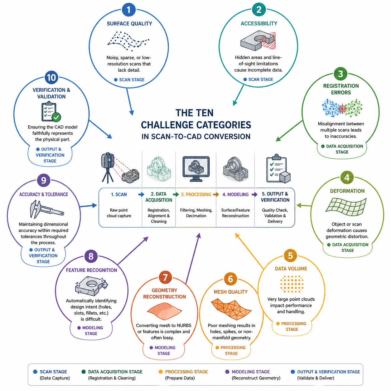
The engineer who has never encountered a scan-to-CAD conversion problem has not done enough scan-to-CAD conversion. The workflow looks straightforward in theory: scan the part, process the data, reconstruct the CAD model. In practice, the gap between those three steps contains ten categories of problems that each have their own technical root cause, their own detection method, and their own fix strategy. Understanding them transforms what feels like a frustrating collection of random failures into a systematic set of manageable engineering challenges.
This article exists because the previous article in this series, covering the complete reverse engineering workflow from scan to CAD model, documents what a successful workflow looks like. This article covers what happens when it does not go according to plan, which in practical engineering work is frequently. The challenges described here are not edge cases. They are the routine obstacles that every engineer executing scan-to-CAD conversion at production quality will encounter within their first ten projects.
Each challenge is covered with the specificity that makes it actionable: the underlying cause that explains why the problem occurs, the detection method that identifies it reliably (because many of these challenges are not immediately obvious), the primary fix strategy, and the alternative approaches when the primary fix is not sufficient or not applicable. The article closes with the legal and intellectual property considerations that every engineer doing competitive reverse engineering must understand, a topic that most technical content on this subject ignores entirely.
Challenge Overview: Root Cause, Detection, and Fix Strategy at a Glance
The following table maps all ten major challenge categories to their root cause, detection method, primary fix strategy, and severity classification. Use it as a quick reference when diagnosing a specific problem, and refer to the detailed section for each challenge for the full technical explanation.
Challenge
Root Cause
Detection Method
Primary Fix Strategy
Severity
Reflective and dark surface scan failure
Specular reflection or light absorption prevents pattern capture
Different materials reflect light differently within same scan
Boundary noise at material interfaces
Separate scan sessions per material, CT for embedded parts
High
CAD reconstruction quality vs mesh fidelity
Parametric reconstruction cannot capture all mesh detail
Deviation analysis of reconstructed CAD vs mesh
Hybrid approach: parametric for prismatic, NURBS for organic
Medium
Color and texture loss in geometry-only formats
STEP and IGES carry no color or texture data
Visual comparison, missing appearance data
Supplement with OBJ+MTL, VRML, or 3D PDF with texture
Low to Medium
The severity ratings reflect the impact on final CAD model quality if the challenge is not addressed: Very High challenges produce CAD models that are dimensionally incorrect and cannot be used for reproduction or manufacturing without causing failures. High challenges produce models with specific inaccurate regions. Medium challenges degrade model quality or workflow efficiency without necessarily invalidating the output.
Challenge 1: Reflective, Dark, and Transparent Surfaces
Surface optical properties are the most frequently encountered obstacle in structured light and laser line scanning, and they cause the most varied and unpredictable data quality problems. Three distinct surface conditions each create different failure modes: highly reflective surfaces, dark or absorptive surfaces, and transparent or translucent surfaces.
Reflective Surfaces: Specular Glare and Data Voids
Polished metals, chrome plating, mirror finishes, and wet surfaces create specular reflection: they reflect the scanner’s projected light pattern back at a specific angle rather than diffusing it across the field of view. When the camera is not positioned at the exact specular angle, it receives no light from that surface area and records no data. When it is near the specular angle, it receives saturated light that overwhelms the camera sensor, producing blown-out pixels with no useful fringe deformation information.
The characteristic signature of specular reflection in a point cloud is a pattern of voids surrounded by noisy data: the center of the reflection zone has no points (the camera received no return), surrounded by a fringe of noisy points (the camera received partially saturated return with corrupted fringe data). Attempting to fill these voids during mesh repair produces geometrically incorrect surfaces because the hole-filling algorithm has no scan data to work from in that region.
The primary fix is matte scanning spray: a temporary aerosol coating of white titanium dioxide or zinc oxide particles that provides a diffuse, lambertian-reflective surface for consistent light return from any camera angle. Applied correctly in 2 to 3 thin coats from 200 to 300mm distance, the coating is 5 to 15 microns thick and dries to a matte white finish that the scanner reads easily. For most mechanical engineering applications, this coating thickness is negligible relative to part tolerances. For precision surface measurements where the coating thickness matters, use the thinnest possible application and account for the coating thickness in your dimensional analysis.
A secondary approach is to adjust the scanner’s exposure settings to reduce sensitivity and capture less of the saturated reflection, or to reposition the scanner to avoid the specular angle for the most problematic surfaces. Most professional scanning systems allow per-scan exposure adjustment, and some support automatic multi-exposure capture (HDR scanning) that takes multiple exposures in the same position and combines the best data from each, effectively handling mixed reflectivity across a complex surface in a single capture.
Dark and Black Surfaces: Light Absorption
Dark surfaces, particularly matte black coatings, anodized aluminum, carbon fiber, and black rubber, absorb 80 to 95 percent of incident light. The scanner’s projected pattern reaches the surface but the reflected intensity is too low for the camera to detect reliable fringe deformation. The result is sparse, noisy point data rather than complete voids, because some light does return but the signal-to-noise ratio is too low for accurate position calculation.
The fix is the same matte scanning spray, which converts the dark surface to a diffuse white reflector. For parts where spray cannot be used (due to temperature sensitivity, chemical incompatibility, or requirement for an absolutely uncoated surface), alternative approaches include increasing the scanner’s projector intensity (if the system supports it), increasing exposure time, or switching to a laser line scanner rather than a structured light system, as laser line scanners are generally less sensitive to surface color than white-light structured light systems.
Transparent and Translucent Surfaces: Subsurface Scattering
Transparent materials (glass, clear acrylic, polycarbonate lenses) transmit the scanner’s light pattern rather than reflecting it, producing no data at all from the surface. Translucent materials (frosted plastic, skin, some composites) allow light to penetrate the surface and scatter within the material before returning, a phenomenon called subsurface scattering. This produces surface data that is systematically displaced from the true surface position by the scattering depth, typically 0.1 to 2 mm depending on material type and thickness.
Scanning spray converts transparent surfaces to opaque reflectors, resolving both problems. For parts where transparency is a functional property that must be preserved (optical components, light pipes, lenses), CT scanning is the only practical alternative for capturing the surface geometry without any surface preparation.
Surface Preparation Quick Reference Polished steel, chrome, aluminum mirror finish: 2 to 3 coats matte scanning spray. Anodized aluminum, black paint, carbon fiber: 2 to 3 coats matte scanning spray. Clear glass, polycarbonate, acrylic: 2 to 3 coats matte scanning spray (destroys transparency – use CT if optical function must be preserved). Rubber or silicone: Spray carefully – rubber can absorb spray solvent. Test on an inconspicuous area first. Alternative: use blue LED structured light rather than white LED for better rubber surface response.
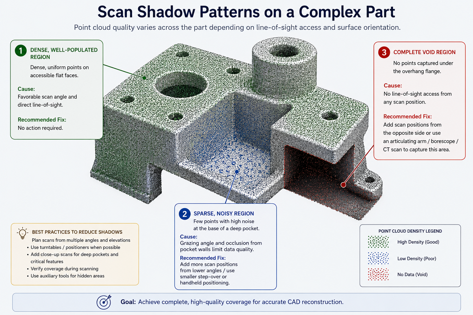
Challenge 2: Inaccessible Geometry and Scan Shadows
Optical scanners, including structured light, laser line, and photogrammetry systems, share an absolute limitation: they can only capture surfaces they can see. Every feature that is occluded, recessed, or hidden behind another surface during scanning creates a scan shadow: a region of the point cloud with no data because no scan position had line-of-sight access to that surface.
Common examples include the interior of deep pockets, undercut features, the back face of a flange, the interior of a tube or bore, and the region under an overhang. In complex assemblies, adjacent components shadow each other, leaving interface surfaces without scan coverage.
Multi-Position Scanning to Minimize Shadows
The primary strategy for managing scan shadows is systematic multi-position scanning: planning the scan sequence so that every surface receives at least one scan position with acceptable line-of-sight access, even if that position is geometrically difficult to achieve. Before beginning any scan session on a complex part, walk around the part and identify every surface that will be difficult to access optically. Then plan the scanner positions, fixture orientations, and part repositioning steps needed to capture each of those surfaces.
For deep pockets and internal channels, scan from inside the pocket with the scanner tilted to the maximum possible angle. Most structured light systems capture data reliably at angles up to 45 degrees from the surface normal. Beyond this angle, the projected pattern becomes too foreshortened for accurate fringe deformation measurement, and data quality degrades rapidly. Laser line scanners generally have wider acceptance angles and can capture data at 60 to 70 degrees from normal in some configurations.
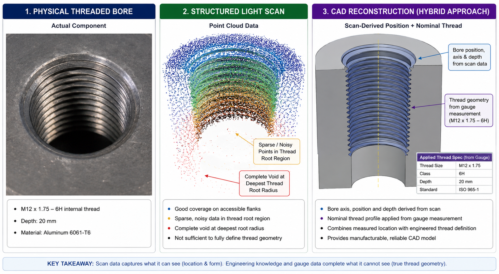
Industrial CT for Enclosed Internal Geometry
When optical scanning cannot capture required internal geometry regardless of the number of scan positions, industrial CT scanning is the definitive solution. CT sees through the material from all angles simultaneously, capturing internal surfaces, channels, wall thicknesses, and enclosed features that no optical scanner can reach. For hydraulic manifolds, castings with complex internal passages, sealed housings, and any assembly with interior surfaces that define function, CT is not an optional alternative to optical scanning. It is the only technology that captures the complete geometry.
The practical limitation is that CT requires access to a CT system (either in-house or as a service), it is slower than optical scanning, and it has part size constraints. For engineering teams that regularly reverse engineer complex internal geometry, CT scanning as a service from an industrial metrology provider is a practical and cost-effective solution for the cases where optical scanning cannot reach the needed surfaces.
Reconstructing Inaccessible Geometry by Inference
When CT scanning is not available and scan shadows cannot be eliminated through multi-position scanning, the engineer must reconstruct the unseen geometry by inference: using the surrounding scan data to determine what the hidden geometry must be, based on engineering knowledge, visual reference images, or measured cross-sections.
For features that follow predictable manufacturing patterns (a drilled and tapped hole that continues through to a visible back surface, a groove that follows a radius consistent with the cutter diameter visible in the surrounding material, a blind bore whose depth can be estimated from the visible part thickness minus a minimum wall thickness), reasoned reconstruction produces reliable results. For truly arbitrary hidden geometry with no inferential constraints, the CAD model must document the unknown region explicitly in its drawing annotations and inspection requirements.
Challenge 3: Part Deformation During Scanning
Part deformation during scanning is the most damaging challenge in the list because it is invisible in the scan data. The scanner captures the geometry of the part as it actually is during the scan, including any deformation caused by its own weight, by the fixture holding it, or by the thermal environment. The resulting CAD model accurately represents the deformed part, not the part’s true geometry, and the engineer may not discover the problem until a manufactured replacement using the CAD model does not fit correctly.
Gravity Sag in Large or Flexible Parts
Gravity sag is a common deformation mode for large parts, thin flexible sheets, rubber and elastomer components, and any part where the ratio of part mass to stiffness is high enough that measurable deflection occurs under self-weight. A long, thin aluminum extrusion lying horizontally will sag at its center. A rubber seal gasket deforms significantly under its own weight if unsupported. Even a relatively stiff steel bracket can show 50 to 200 microns of sag at its free end when cantilevered, which exceeds the accuracy of a high-quality structured light scan and would produce measurable dimensional error in the resulting CAD model.
The fix is fixture design: supporting the part in a way that replicates its functional configuration, or in a way that eliminates all gravity-induced deflection. For a part that is normally bolted flat to a surface, scan it in that bolted configuration with the mounting surface as the primary datum. For a part whose functional configuration cannot be determined, scan it from multiple orientations and compare the results to identify any gravity-dependent deformation in the data.
Fixture-Induced Stress
Fixtures that clamp or constrain a flexible part to hold it for scanning introduce their own deformation. The clamping force distorts the part geometry in the clamped region and can induce bending or twisting throughout the part. This is particularly problematic for thin-walled plastic parts, sheet metal, and rubber or silicone components. Fixture-induced deformation can be worse than unconstrained gravity sag if the fixture is not designed carefully.
Use the minimum clamping force required to hold the part stable during scanning. For very flexible parts, consider non-contact fixturing: a conformal nest made from foam or sand that supports the part across its full surface without applying point or line loads. For parts where any deformation is unacceptable, use gravity-independent measurement methods: CMM probing with the part in its functional installation configuration, or CT scanning where the part can be scanned while resting naturally without clamping.
Thermal Deformation
Temperature differences between the scan environment and the part’s functional operating temperature cause dimensional changes through thermal expansion. For a 200mm aluminum part (coefficient of thermal expansion approximately 23 microns per millimeter per degree Celsius), a 10 degree Celsius temperature difference between the scan environment and the nominal temperature produces 46 microns of dimensional change, which exceeds the measurement tolerance for precision features.
Ensure the part is at thermal equilibrium with the scan environment before scanning begins. For a part that has been transported from a cold or hot environment, allow 30 to 60 minutes of equilibration time before scanning. For precision work, record the ambient temperature during scanning and apply a thermal expansion correction to the scan data if the scanning temperature differs from the reference temperature (typically 20 degrees Celsius for engineering dimensional measurement per ISO 1 standard).
Deformation Risk Assessment Low risk: Rigid metal parts under 300mm, wall thickness over 5mm, scanned in ambient conditions. Medium risk: Parts over 500mm, thin-walled structures under 3mm, machined from stock (residual stress). High risk: Rubber/elastomer parts, flexible plastics, large sheet metal, assembled multi-material parts, parts transported from extreme temperatures. For High risk parts: design a dedicated scanning fixture, verify deformation by comparing scans in two different orientations, and consult a metrology engineer before committing the scan data to a CAD reconstruction.
Challenge 4: Distinguishing Wear and Damage from Original Geometry
This is the most engineering-intensive challenge in the entire scan-to-CAD conversion process because it cannot be resolved by any software tool or measurement technique alone. It requires engineering judgment informed by multiple lines of evidence, and getting it wrong produces a CAD model that faithfully reproduces a damaged part rather than the original design.
The specific problem: the scanned part has been in service and has accumulated geometric changes from in-service wear, impact damage, corrosion, plastic deformation, or fatigue-related distortion. The scan accurately captures the current state of the part, but the reverse engineering goal is typically to reproduce the original design geometry, not the worn state. The scan data alone cannot tell you what is original design geometry and what is accumulated damage.
Types of Geometric Change from Service Life
Abrasive wear produces gradual, smooth reduction in material at contact surfaces. It is typically most severe at sliding interfaces, sealing surfaces, and bearing surfaces. In a scan, worn surfaces appear as slight concavities or reduced thicknesses relative to the expected nominal geometry. Wear patterns are often asymmetric (one side wears faster than the other due to loading direction) and have a smooth, gradual boundary with unworn regions.
Impact damage produces local depressions, cracks, or material loss at specific locations from point loading events. These are typically more localized than wear and have sharper boundaries between damaged and undamaged regions. Impact damage can produce significant local deformations: a 20mm dent in a steel plate from a dropped tool can represent 2 to 5mm of surface displacement.
Corrosion produces surface texture changes and material loss at chemically active surfaces. Early-stage corrosion produces a roughening of the surface texture that increases scan noise without significant dimensional change. Advanced corrosion produces measurable material loss and surface pitting that significantly corrupts the scan data in affected regions.
Plastic deformation from overloading produces permanent geometric change throughout the affected region. Unlike wear (which only removes material from contact surfaces) or impact damage (which is localized), plastic deformation can alter the geometry of large regions of the part in ways that are difficult to identify from the scan alone without reference to the original design dimensions.
Strategies for Identifying Wear and Damage
Use multiple evidence sources in combination to identify which geometric deviations are wear and which are original design features:
Compare to surviving unworn regions: Most worn parts have some surfaces that were not in contact with anything during service and remain at or near the original geometry. Comparing the worn surfaces to these reference regions establishes what the original dimensions likely were.
Statistical analysis of the point cloud: Wear and damage produce localized outlier deviations from the general surface geometry. Fitting a geometric primitive to the entire surface and examining the residual deviation distribution identifies regions where the deviation is anomalously large, indicating either damage or an intentional geometric feature. Large, localized positive deviations suggest material buildup or deformation. Large, localized negative deviations suggest wear or removal.
Multiple part comparison: If more than one example of the same part is available, scanning multiple examples and comparing them isolates genuine design geometry (consistent across all parts) from wear and damage (variable between parts depending on service history).
Physical reference standards: Assembly drawings, inspection sheets, or supplier part numbers from the original program may establish nominal dimensions against which the scan can be compared, identifying the magnitude and location of all deviations from nominal.
Manufacturing process inference: An engineer familiar with the manufacturing process for the part type can identify which surfaces would have been machined to a precise nominal and which would have been cast or formed with greater variation. Machined surfaces in an unworn state should have scan residuals close to the scanner’s measurement uncertainty. Larger residuals on machined surfaces indicate either wear or damage.
Challenge 5: The Symmetry Assumption Trap
The symmetry assumption trap is a specific error pattern that is extremely common among engineers who are new to scan-to-CAD conversion and surprisingly persistent among experienced ones. It occurs when an engineer, modeling a part that appears symmetric from visual inspection, applies symmetry in the CAD reconstruction without verifying from the scan data whether the part is actually symmetric within measurement precision. The result is a CAD model that is more symmetric than the physical part, which can cause fit errors in asymmetric assembly interfaces and incorrect mass properties.
Most manufactured parts that are nominally symmetric are not perfectly symmetric in their as-built state. Casting, forging, and injection molding processes all introduce manufacturing variation that is rarely perfectly symmetric. In-service loading can induce asymmetric wear or deformation. And some parts that appear symmetric actually have subtle intentional asymmetry that serves a functional purpose, such as a poka-yoke feature that prevents incorrect installation.
Detecting Asymmetry in Scan Data
The detection method is a mirror comparison analysis: reflect the scan data about the presumed plane of symmetry and compute the deviation between the original data and its mirror image. If the part is truly symmetric within the measurement uncertainty of the scanner, the deviation between original and mirror should be uniformly distributed at or below the scanner’s noise level. If specific regions show systematic deviation above the noise level, those regions are genuinely asymmetric.
Most professional scan processing software (Geomagic, PolyWorks, ZEISS Inspect) includes symmetry analysis tools that perform this comparison automatically and display the results as a color map. This analysis should be performed before any symmetry is applied in the CAD reconstruction, and its results should be documented in the project record.
The Right Response to Detected Asymmetry
When the symmetry analysis reveals asymmetry, the engineer must determine whether it represents manufacturing variation that should be idealized away or intentional design asymmetry that must be preserved. Manufacturing variation is typically random in distribution and magnitude, with no consistent directionality. Intentional design asymmetry is typically consistent across multiple examples of the same part and associated with a functional interface or assembly constraint.
For manufacturing variation: apply symmetry in the CAD model and document the decision with the measured asymmetry magnitude. For intentional asymmetry: model the asymmetric geometry explicitly and investigate whether the asymmetry is a poka-yoke feature, a balancing provision, or a functionally significant geometric difference that affects part performance or assembly.
Challenge 6: Thread and Fine Feature Reconstruction
Thread reconstruction from scan data is a universally acknowledged limitation of optical scanning, and it is one area where the standard workflow must be supplemented by a different measurement approach. No current optical 3D scanner reliably captures thread geometry with enough accuracy for thread profile reconstruction. Thread pitches for common metric threads range from 0.35 mm for M2 to 3 mm for M36. The helix angle, flank angle, root radius, and crest geometry of a standard thread are all at a scale that is either below the resolution of most industrial scanners or creates such extreme surface angle variation that the scan data is too noisy to extract meaningful thread geometry.
Why Threads Cannot Be Scanned Reliably
The fundamental problem is geometry, not scanner quality. Thread flanks on a metric thread have a 60-degree included angle, meaning the thread faces are inclined at 30 degrees from the axis. At the root of the thread, the scanner must capture a surface that is deeply recessed between two flanks, at an angle that may exceed the scanner’s angular acceptance. Even when data is captured in the thread region, the thread root and crest radii are typically below the spatial resolution of most structured light systems (typically 0.1 to 0.3 mm point spacing for medium parts). The resulting point cloud in the threaded region is too sparse and noisy to extract reliable thread profile data.
The Hybrid Measurement Approach
The correct approach for threaded features is hybrid measurement: scan the part optically to capture all non-threaded geometry, and measure all threaded features separately using a method appropriate for thread metrology: optical comparator, thread gauge, thread micrometer, or CMM probing with a thread-pitch measuring strategy.
The optical scan provides the position of the threaded bore’s axis (captured from the cylindrical bore surface surrounding the thread), the bore diameter (from the cylinder fit to the major diameter region), and the depth of blind holes. CMM measurement or gauge measurement provides the thread specification: pitch, thread form (metric, UNC, UNF, ACME, etc.), tolerance class, and depth of engagement. The CAD reconstruction combines both sources: the scan-derived position and the gauge-derived thread specification.
Fine Features Below Scanner Resolution
Beyond threads, any geometric feature whose characteristic dimension is smaller than the scanner’s point spacing is potentially affected by resolution-limited reconstruction. Knurling, fine surface textures, small radii (under 0.2 mm), sharp edges (the scanner captures a blend radius that does not exist in the physical part), and fine engraved markings are all below the resolution of most industrial scanners.
For sharp edges and small radii: document the expected nominal value (based on manufacturing process knowledge or reference drawings) and use this nominal value in the CAD model rather than trying to extract it from the scan. A milled part has sharp internal corner radii equal to the end mill radius used. A cast part has minimum radii defined by the mold tool design. These values are more reliably determined from manufacturing process knowledge than from scan data.
Challenge 7: Data Volume and Processing Performance
Modern structured light scanners produce point clouds of 5 to 50 million points per scan position, and complex parts requiring 20 to 40 scan positions produce raw datasets of 100 million to 2 billion points. Processing, registering, and reconstructing CAD geometry from datasets at this scale places substantial demands on workstation hardware, and underpowered workstations are one of the most common practical bottlenecks in scan-to-CAD workflows, causing software crashes, multi-hour processing times for operations that should take minutes, and workflow interruptions that disrupt the engineer’s focus.
The Computational Bottleneck Explained
Point cloud processing operations, particularly ICP registration (which iteratively compares millions of point pairs), mesh generation (which builds topological relationships across hundreds of millions of points), and NURBS surface fitting (which involves large matrix operations), are computationally intensive in specific ways that determine which workstation specifications are most impactful.
RAM is the primary constraint for large dataset operations: a 500-million-point dataset requires 6 to 10 GB of RAM just to hold the point coordinates in memory before any processing begins, and processing operations create temporary copies and work arrays that multiply the memory requirement by 3 to 5 times. Geomagic Design X recommends a minimum of 32 GB RAM for complex scan projects. 64 GB is strongly preferred for large industrial parts. 128 GB is appropriate for very large assemblies or complex organic forms with dense scan data.
CPU performance matters for single-threaded operations like ICP refinement and geometry healing, which benefit from high per-core clock speeds. GPU acceleration is increasingly used by modern scan processing software for mesh generation and surface fitting. Fast NVMe SSD storage is essential because scan datasets routinely exceed the size that fits in RAM and must be streamed from disk during processing. A mechanical hard drive accessing 100 GB of scan data during processing creates wait times that can multiply the total workflow time by 5 to 10 times compared to NVMe storage at the same dataset size.
Practical Strategies for Managing Data Volume
Uniform downsampling before any processing: Reduce the point cloud to the minimum density that preserves all relevant geometric detail (typically 0.05 to 0.2mm point spacing for industrial parts). This reduction alone cuts processing time by 80 to 95 percent for most operations.
Region-of-interest processing: Process the scan in sections rather than all at once. Work on each sub-region at the resolution it requires, combining the final processed regions at a later stage.
64-bit operating system and application: Verify that the scan processing software is running in 64-bit mode (not 32-bit compatibility mode), which allows access to more than 4 GB of RAM per process.
Temporary file location: Configure the scan software’s scratch/temporary file directory to point to the fastest available storage (NVMe SSD, not a network drive or mechanical HDD).
Background process management: Close all non-essential applications during intensive scan processing operations to maximize available RAM and CPU bandwidth for the scan software.
Minimum Workstation Specification for Scan-to-CAD Work WORKSTATION REQUIREMENTS FOR SCAN-TO-CAD CONVERSION:
SMALL PARTS (under 200mm, single setup, < 50M points): CPU: Intel i7 or AMD Ryzen 7, 8+ cores, 3.5GHz+ RAM: 32 GB DDR4 (3200MHz recommended) GPU: NVIDIA Quadro/RTX 4000+ or AMD Radeon Pro equivalent Storage: 500 GB NVMe SSD (OS+Software) + 1TB NVMe SSD (project data) Display: 2560x1440 IPS or better (color accuracy matters for deviation maps)
LARGE ASSEMBLIES (600mm+, complex multi-material, >500M points): CPU: Dual-socket Xeon or AMD EPYC, 32+ cores total RAM: 128 GB minimum - 256 GB preferred GPU: NVIDIA RTX A6000 or better (VRAM >= 24 GB) Storage: RAID-0 NVMe array for scratch data, minimum 4 TB Note: Consider cloud processing for extreme dataset sizes
Challenge 8: Multi-Material Scan Artifacts
Parts made from multiple materials with different optical properties create a specific and often overlooked scan challenge: the scanner is calibrated and optimized for one set of optical conditions, but the part presents multiple different conditions simultaneously. At the boundary between materials with different reflectivity or color, the scanner produces noisy or incorrect data in a zone that extends 1 to 5 millimeters on either side of the material interface.
A metal housing with a rubber gasket face is a classic example. The metal face may require normal exposure settings for the structured light projector. The rubber gasket may require higher exposure and a different angle because it is darker and absorbs more light. At the gasket-to-metal interface, the scan data transitions between these two conditions and produces a noisy boundary zone. The CAD reconstructed from this data shows an inaccurate representation of the interface geometry, which may be the most functionally critical surface in the whole part.
Material Boundary Management Strategies
Strategy 1: Separate scan sessions per material region. Scan the metal faces first with the optimal settings for metal, and the rubber faces in a separate session with adjusted settings. The two sessions are registered together in the same coordinate system using the common coded targets that remain in place throughout both sessions. This approach produces optimal data quality for each material region but requires careful planning to ensure that every surface region belongs clearly to one session or the other, and that enough overlap exists at the boundaries for registration.
Strategy 2: HDR multi-exposure scanning. Some advanced structured light systems support High Dynamic Range scanning, where multiple exposures are taken at each scan position and merged to produce a single point cloud that combines the best data from each exposure level. This effectively handles mixed reflectivity within a single scan session and is the most convenient solution when the equipment supports it.
Strategy 3: Industrial CT for embedded and multi-material assemblies. When the multi-material interface is critical for dimensional accuracy and optical scanning consistently produces poor results at that interface, CT scanning provides accurate geometry for both materials simultaneously, independent of their optical properties. The CT image segments each material based on its X-ray attenuation, which varies by density and atomic composition, providing clean boundaries between material regions even when their optical properties are similar.
Overmolded Parts: A Specific Multi-Material Challenge
Overmolded components, where a soft material is molded over a rigid substrate, present a particular challenge because the soft overmold material deforms differently from the rigid substrate during scanning. If the part is handled or fixtured, the soft overmold deforms at the handling points. If it is scanned without support, gravity causes the overmold to sag. And at the interface between the rigid substrate and the soft overmold, the scan data captures the outer surface of the overmold but provides no information about the substrate geometry beneath it. For overmolded parts where the substrate geometry is functionally critical, CT scanning is the only method that captures both surfaces reliably
Challenge 9: Balancing CAD Model Quality Against Mesh Fidelity
There is an inherent tension in scan-to-CAD conversion between two competing quality goals: geometric fidelity to the scan data and CAD model quality and usability. The mesh produced from the scan data captures every surface irregularity in the physical part: manufacturing variation, surface roughness, minor damage, and scan noise are all present in the mesh as genuine geometric features. A CAD model that precisely reproduces every detail of the mesh is geometrically accurate to the scan but may be extremely difficult to use for design modification, drawing generation, or FEA because of its complexity and lack of parametric structure.
The engineer must make deliberate decisions about how much mesh detail to preserve in the CAD model and how much to idealize. These decisions should be documented so that anyone reviewing the CAD model can understand what level of idealization was applied and what the underlying scan data showed.
The Four Levels of Mesh Detail in CAD Reconstruction
Level 1: Exact mesh representation – The mesh itself is the CAD output. No parametric reconstruction is performed. The mesh is cleaned, repaired, and exported as STL, OBJ, or similar format. Appropriate when the output is for 3D printing, visualization, or simulation where mesh input is accepted and parametric CAD is not required.
Level 2: NURBS surface fit to mesh – NURBS surfaces are fitted to the mesh regions, capturing the general shape including manufacturing variation. The resulting surfaces are smooth but not perfectly prismatic. Appropriate for organic forms and consumer product surfaces where the general manufactured shape is what needs to be captured.
Level 3: Fitted primitives with as-built dimensions – Geometric primitives (planes, cylinders, spheres) are fitted to the mesh and the as-built dimensions are extracted. The CAD model uses these as-built values directly as driving dimensions. Appropriate for exact reproduction where every dimensional deviation from nominal is intentional and must be preserved.
Level 4: Idealized parametric reconstruction – Geometric primitives are fitted to the mesh, nominal dimensions are inferred by rounding to standard values, and the CAD model is built as a fully parametric part with clean feature tree, named parameters, and nominal dimensions. Appropriate for design intent recovery and downstream modification.
The choice between these levels should be made explicitly at the beginning of the project based on the engineering intent defined in the previous article. Defaulting to Level 4 for all projects adds unnecessary modeling time. Defaulting to Level 1 produces output that is often unusable for engineering purposes. Matching the level to the application makes the project efficient and the output fit for purpose.
Challenge 10: Legal and Intellectual Property Considerations
This challenge is categorically different from the nine technical challenges above. It is not a data quality problem or a workflow efficiency problem. It is a legal risk that applies specifically to competitive reverse engineering: the process of scanning and recreating a product manufactured by another organization for the purpose of understanding, competing with, or reproducing that product.
Most scan-to-CAD content for engineers treats this topic as outside scope. That is a significant disservice, because engineers executing competitive reverse engineering programs without understanding the applicable legal framework are exposing their organizations to significant liability. The legal landscape is complex, jurisdiction-dependent, and evolving, and this article is not a substitute for qualified legal advice. But the framework below provides the starting orientation that every engineer doing competitive reverse engineering needs.
What Is and Is Not Protected by Intellectual Property Law
Patents protect functional inventions for a limited term (typically 20 years from filing). A patented mechanism, assembly method, or process cannot be reproduced without a license regardless of how the reproduction is achieved, including by scanning the patented product. Before conducting reverse engineering of a competitor’s product, check whether the functional aspects of interest are patented in the jurisdictions where the reproduction will be manufactured and sold.
Trade dress protects the distinctive visual appearance of a product or its packaging. If the exterior appearance of a product has been registered as trade dress, creating a CAD model that reproduces that appearance and using it to manufacture a competing product may infringe the trade dress even if the functional geometry is not patented.
Copyrights do not typically protect functional three-dimensional objects (as opposed to artistic or sculptural works), but software embedded in a product, digital design files obtained directly from a manufacturer, and decorative or artistic surface features may be copyright-protected.
Trade secrets protect confidential information that has economic value from its secrecy. If information about a product was obtained through a confidential relationship (such as a supplier agreement that included non-disclosure obligations), using that information in a reverse engineering program may breach the confidentiality agreement regardless of whether the information itself is patented.
The Legitimate Uses of Competitive Reverse Engineering
In most jurisdictions, reverse engineering a legally purchased product for interoperability, compatibility, or research purposes is a legally protected activity, provided the product was purchased lawfully and no contractual restriction on analysis was agreed to at purchase. Manufacturing and selling a competing product that reproduces patented functionality is not protected. Manufacturing and selling a competing product that provides the same function through a non-infringing design (informed by understanding the competitor’s approach through reverse engineering) is generally protected.
The practical implication for engineering teams is: document the purpose of the reverse engineering program clearly at its outset. Engineering understanding of a competitor’s design approach for the purpose of designing a non-infringing alternative is legally very different from engineering a direct copy. If the purpose is not clearly documented, a court may draw unfavorable inferences about intent from the existence of scan data and CAD models of a competitor’s product.
Legal Caution This section provides only a general orientation to intellectual property considerations in reverse engineering. It does not constitute legal advice. Before committing to any competitive reverse engineering program that will result in a commercial product, consult qualified intellectual property counsel in the relevant jurisdictions. The legal framework varies significantly between countries (particularly between the US, EU, and Asian jurisdictions), between industries, and based on the specific facts of each situation.
Frequently Asked Questions
Q: Why do I get holes and voids in my 3D scan data?
Holes and voids in 3D scan data have three main causes: line-of-sight limitations (the scanner cannot see surfaces hidden behind other geometry), surface optical properties (reflective surfaces create specular glare voids, dark surfaces create sparse data, transparent surfaces produce no data), and scanner standoff angle violations (data captured at too shallow an angle to the surface produces noise or voids). The fix depends on the cause: add scan positions to reach hidden surfaces, apply matte scanning spray for optical surface issues, or use industrial CT scanning for enclosed internal features that optical scanners cannot reach.
Q: How do I scan reflective metal parts without getting glare artifacts?
Apply a matte anti-glare scanning spray (titanium dioxide or zinc oxide aerosol) to the reflective surface in 2 to 3 thin coats from 200 to 300mm distance. The 5 to 15 micron coating provides a diffuse, lambertian-reflective surface that the structured light scanner can capture accurately from any angle. The coating is temporary and can be washed off after scanning with water or a mild solvent. For highly polished precision surfaces where coating thickness matters, apply the thinnest possible coat and account for the coating thickness (typically 5 to 10 microns) in your dimensional analysis. Alternative approaches include HDR multi-exposure scanning or adjusting the scanner angle to avoid the specular reflection zone.
Q: Can I accurately reconstruct thread dimensions from a 3D scan?
No, optical 3D scanning cannot reliably capture thread geometry at the accuracy required for thread specification reconstruction. Thread pitches for common fasteners range from 0.35mm to 3mm, and the thread root radius and flank geometry are at a scale below the resolution of most industrial scanners. The correct approach is hybrid measurement: scan the part optically to capture the bore position and major diameter, then measure the thread specification separately using a thread gauge, optical comparator, or CMM probing. Combine both data sources in the CAD reconstruction: scan-derived position and gauge-derived thread specification.
Q: How do I tell whether a dimensional deviation in my scan is wear or original design geometry?
Compare the deviation against multiple evidence sources: surviving unworn surfaces on the same part (which should remain near the original design geometry), statistical analysis of the point cloud to identify systematic vs random deviations (wear is typically smooth and directional, design features are consistent and bounded), comparison across multiple examples of the same part if available (wear varies with service history, design features are consistent), and manufacturing process inference (machined surfaces should have scan residuals near the scanner noise level if unworn). When in doubt, document the uncertainty explicitly and flag the affected dimensions for verification before any manufacturing commitment.
Q: What workstation specifications do I need for scan-to-CAD work?
For medium-complexity industrial parts producing 50 to 500 million points: 64 GB RAM (minimum, 128 GB preferred), Intel i9 or AMD Threadripper CPU with 16+ cores, NVIDIA RTX 4080 or better GPU with at least 16 GB VRAM, and NVMe SSD storage for both the operating system and project data. RAM is the primary bottleneck: scan processing creates multiple temporary copies of large datasets simultaneously. NVMe SSD storage is the second most impactful specification because large datasets must be streamed from disk during processing. A mechanical hard drive accessing large scan data can multiply total processing time by 5 to 10 compared to NVMe storage.
Q: Is reverse engineering a competitor’s product legal?
It depends on the jurisdiction and the specific purpose. In most jurisdictions, reverse engineering a legally purchased product for purposes of interoperability, research, or designing a non-infringing alternative is a legally protected activity. However, reproducing patented functionality, infringing registered trade dress, or using information obtained under a confidentiality obligation can create significant legal liability regardless of how the reverse engineering was conducted. The specific legal framework varies between countries and industries. Before commencing any competitive reverse engineering program intended to result in a commercial product, obtain qualified legal advice from intellectual property counsel in the relevant jurisdictions. Document the purpose of the program clearly at its outset.
Q: Why does my CAD model not match the scan data in the final deviation analysis?
Large deviation analysis discrepancies have several common causes: incorrect primitive fitting (the plane or cylinder fit did not capture the true geometry of that region), design intent rounding to nominal that moved a dimension outside the measurement uncertainty range, part deformation during scanning that was not detected and corrected, wear or damage on the scanned part that was inadvertently reproduced in the CAD model, or a registration error in the point cloud that introduced a systematic misalignment. The deviation analysis color map identifies exactly where the CAD model deviates from the scan. Return to the reconstruction for each high-deviation region and re-examine the fitting or modeling decision that produced the deviation.
Conclusion:
The ten challenges covered in this article account for the overwhelming majority of the problems that engineers encounter in scan-to-CAD conversion workflows. None of them are random or unpredictable. Each has a specific root cause that explains why it occurs, a specific detection method that identifies it before it corrupts the final output, and a specific fix strategy that resolves it when it is detected.
The pattern across all ten challenges is consistent: problems that are detected early in the workflow are solved cheaply. Problems that reach the CAD reconstruction stage, or worse, the deviation analysis stage, are solved expensively. Surface preparation before scanning is ten minutes. Discovering missing scan data after the scanner has been returned to its case and the part has been cleaned is a rescan request. Detecting asymmetry before applying symmetry in CAD is a five-minute analysis. Discovering the asymmetry error after completing the parametric reconstruction is an hours-long rework.
Build the pre-scan checklist, the intermediate quality checks, and the final deviation analysis into every scan-to-CAD project as non-negotiable workflow steps. The engineers who execute scan-to-CAD conversion at the highest reliability are not the ones who never encounter these challenges. They are the ones who detect and address each challenge at the earliest possible workflow stage, before it becomes a project-level problem.
Build your complete scan-to-CAD knowledge with our guide to the full reverse engineering workflow, CAD data translation problems, parametric modeling best practices, and multi-body modeling techniques.
When a large engineering program runs into trouble, the diagnosis almost always traces back to the same category of failure: the left-hand team did not know what the right-hand team was doing until the two sub-systems came together for integration, and the interface between them was wrong. Not slightly wrong. Wrong in ways that require significant redesign, tooling rework, and schedule recovery that consumes the program’s margin and sometimes exceeds it.
This failure mode has a name in systems engineering: interface mismanagement. And it has a technical solution in CAD: the master model. A master model is a CAD architecture in which a single controlled source file defines the critical interfaces, envelope geometry, and spatial constraints that all other components in the program must respect. It is the engineering equivalent of a master plan: drawn first, referenced by everyone, and changed only through a controlled process that propagates the change to every dependent design automatically.
Master models are not a new idea. Aerospace programs have used skeleton-driven assembly design in CATIA and NX for decades. Automotive programs at tier-one suppliers have built complex powertrain and chassis designs using Creo skeleton models for nearly as long. The challenge is that this approach, which transforms how large teams work together, is rarely documented comprehensively enough for engineering leaders to make the decision to adopt it with confidence, or for the engineers who will implement it to do so correctly from the beginning.
This article provides that comprehensive foundation. It covers what master models are and why they work at a structural level, the specific benefits they deliver on large programs with specific and quantified examples, how master models are implemented differently across the major CAD platforms, how to govern them so they remain an asset rather than becoming a bottleneck, and where master models break down and how to prevent those failures. For engineering teams deciding whether to adopt master modeling on an upcoming program, this article gives you the information to make that decision with confidence.
What a Master Model Is and How It Works
A master model in CAD is a specially designated file or set of files that serves as the single authoritative source of critical geometric information for an entire assembly or program. Every component in the program that depends on that information references it from the master model rather than defining it independently. When the master model changes, all dependent components update automatically through the parametric linkages that connect them to the master.
The most immediately apparent benefit is change propagation: a design change that affects ten components in the program requires one edit to the master model rather than ten edits to ten separate part files. The less immediately obvious but ultimately more valuable benefit is interface integrity: because all components that share an interface draw that interface geometry from the same master model source, the interface is inherently consistent. There is no scenario in which two components define the same interface differently and diverge over time.
Master Models vs. Skeleton Models: Understanding the Distinction
The terms master model and skeleton model are often used interchangeably, but they describe slightly different concepts that are worth distinguishing precisely. A skeleton model is a lightweight geometry file that contains reference geometry only: planes, axes, curves, and key points that define the layout and interfaces of an assembly, with no solid bodies and no mass properties. Its purpose is to serve as a spatial reference framework.
A master model is a broader concept that encompasses skeleton models but extends to any controlling file that drives dependent geometry. A master model may contain solid bodies (for multi-body modeling approaches where components are extracted from a solid master), surface bodies (for surface-driven product designs), or purely reference geometry (in which case it is functionally identical to a skeleton).
In Creo, the formal skeleton model is a specific file type with a special designation. In SolidWorks, the closest equivalent is a layout sketch or master sketch in a part file or an in-context driven assembly. In NX, the WAVE Geometry Linker establishes similar inter-part relationships without requiring a dedicated skeleton file type.
For the purposes of this article, master model refers to the broader architecture: any CAD design in which a designated controlling file or set of files defines the critical shared geometry that drives all dependent components. The specific implementation varies by platform, but the architectural principle and the benefits it delivers are consistent.
The Reference Architecture: What the Master Model Contains
A well-designed master model does not contain everything. It contains only the information that must be consistent across multiple components or sub-systems. Putting too much in the master model creates an unwieldy file that is slow to open and difficult to manage. Putting too little defeats the purpose by leaving critical interfaces undefined at the system level.
The appropriate content of a master model for a complex mechanical assembly includes:
Critical interface surfaces and planes: the mounting faces, parting surfaces, and contact planes between major sub-systems that must be consistent for the assembly to close correctly
Envelope geometry: the maximum space claim of each sub-system, defined as a volume or set of bounding surfaces that establishes what space each sub-system owns and what space is available to adjacent sub-systems
Key dimensions and parameters: the hole patterns, bolt circles, shaft diameters, channel widths, and other dimensions that appear in multiple components and must be changed synchronously when any one of them changes
System-level axes and reference planes: the coordinate system and primary reference planes that establish a consistent orientation framework for the entire program
Kinematic constraints: the motion limits, travel envelopes, and clearance volumes for moving components within the assembly, defined at the system level so all fixed components can verify clearance against them
What is a master model in CAD? A master model in CAD is a designated controlling file that defines critical interface geometry, envelope dimensions, and system-level parameters for a complex assembly. All component files in the program reference the master model parametrically, so design changes made in the master propagate automatically to every dependent component. Master models enable large engineering teams to work concurrently on different sub-systems with confidence that their interfaces will be compatible at integration.
The Five Core Benefits of Master Model Architecture on Large Programs
The case for master models on large engineering programs is not made by theory alone. It is made by specific, measurable benefits that affect program schedule, cost, quality, and team productivity in ways that are directly traceable to the master model architecture. The following five benefits represent the consistent outcomes reported by engineering teams that have implemented master modeling on complex programs.
Benefit 1: Interface Integrity by Design
The most costly category of engineering failure in complex assembly programs is interface mismatch: two components, designed by different engineers or different teams, that do not fit together at their shared interface. These mismatches are discovered during integration, which is the most expensive stage of development to make corrections.
A published study in product development literature finds that design changes made during integration cost 10 to 100 times more than the same changes made during detailed design, due to the cascading effect on tooling, procurement, testing, and schedule.
Master model architecture eliminates this failure mode for all interfaces that are defined in the master. When two components both draw their shared interface from the master model, they are by construction geometrically compatible. The interface surface is not defined twice by two engineers who must agree: it is defined once in the master and referenced by both.
Interface mismatch at that boundary is geometrically impossible unless the master itself is wrong, and the master is controlled by a governance process that prevents unauthorized changes.
A tier-one automotive supplier implementing master model-based design for a new transmission housing program reported that first-assembly fit issues dropped by 78 percent compared to the previous program, which was designed using bottom-up assembly without a master model. The reduction was directly attributable to the master model architecture eliminating the category of interface mismatch errors that had been the dominant source of assembly failures on the previous program.
Benefit 2: Concurrent Engineering at Full Team Scale
Bottom-up assembly design serializes the work: mechanical team finishes before systems team starts, electrical team waits for mechanical to define routing space, manufacturing engineering cannot begin fixture design until all parts are final.
This serialization is not inefficiency through poor planning. It is a structural consequence of not having a defined spatial framework within which teams can work concurrently. Without a master model, there is nothing reliable for the second team to reference until the first team’s work is complete.
A master model breaks this serialization. Once the master model is established with the envelope geometry, key interfaces, and system-level parameters, every sub-system team has a defined spatial contract within which they can work simultaneously. The mechanical team knows the space available to them. The electrical team knows where they cannot run cables.
The manufacturing engineering team knows the part envelope and can begin fixture and tooling design in parallel with the detailed design phase.
In a program without a master model, these teams work sequentially, and the total program schedule is the sum of all phases. In a program with a master model, the teams work concurrently, and the total program schedule is approximately the length of the longest critical path.
For a program with four major sub-system teams, the theoretical schedule compression from full parallelism is up to 75 percent of the sequential duration. In practice, dependencies and integration requirements limit the actual compression, but programs consistently achieve 30 to 50 percent schedule compression on the concurrent engineering phases through master model-enabled parallelism.
Benefit 3: Change Propagation That Scales With Program Complexity
In a bottom-up assembly, a single change to a critical interface dimension requires finding and updating every component that references that dimension. For a program with 200 components that share a common mounting bolt pattern, changing the bolt circle diameter means visiting 200 files. Each visit carries the risk of missing the change in one file, of introducing an error during the manual update, or of the change triggering a downstream failure in that file’s feature tree that requires additional repair.
The manual update burden scales linearly with the number of affected components. The error probability scales with the update burden.
With a master model, the same change requires one edit: the bolt circle diameter parameter in the master model. Every component that references the master model’s bolt pattern updates automatically on the next rebuild. The engineer does not need to identify which components are affected, does not need to open each one individually, and does not risk missing a component or introducing an error during manual update. The change propagation is complete, consistent, and automatic.
For a medical device design team that rebuilt their primary platform using master model architecture, a customer-requested envelope size change that would have taken three weeks in their previous bottom-up workflow was completed in two days. The master model defined the envelope geometry. All 87 components in the assembly referenced it.
Changing the master envelope dimensions triggered a full rebuild that updated all 87 components simultaneously. Two days of verification and review replaced three weeks of manual updates.
Benefit 4: Design Intent Preserved at the System Level
Individual component design intent, the parametric relationships within a single part file, is preserved by the techniques covered in the article on reducing CAD rework through design intent. But system-level design intent, the reasoning behind why components relate to each other the way they do, is rarely captured anywhere in a bottom-up assembly. It exists in the engineer’s memory, in meeting notes, and in email threads, but not in the CAD model itself.
A master model makes system-level design intent explicit and self-documenting. The critical interfaces are in the master model, named and organized according to what they represent. The envelope geometry is in the master, with dimensions driven by parameters named after the requirements they encode.
When a new engineer joins the program six months in, they can open the master model and understand the system-level geometry of the entire program in one place, without needing to synthesize that understanding from two hundred individual part files.
This preserved design intent has compounding value: it accelerates onboarding of new team members, it makes the design explainable during customer and regulatory reviews, and it provides the geometric traceability that regulated industries require to demonstrate that design requirements are reflected in the physical geometry of the product.
Benefit 5: Reduced Rework Cost at the Most Expensive Stage
The cost of rework in product development follows a well-documented exponential increase as a program progresses. A design change made at the concept phase costs dollars. Made during detailed design, it costs hundreds. Made after tooling release, it costs tens of thousands. Made during production ramp-up, it can cost hundreds of thousands when tooling changes, scrap, retest, and schedule impact are totaled.
Master models reduce rework cost by moving error detection to the earliest possible stage: the moment the master model is built, all interface errors that would have been discovered at integration are visible and correctable.
This is not a theoretical benefit. It is the direct consequence of the interface integrity benefit described above. Interface mismatches that are caught at the master model stage, weeks or months before any physical parts exist, cost only engineering time to fix. The same mismatches caught at first prototype build cost parts, tooling, assembly labor, test resources, and schedule. The master model’s primary economic value is the elimination of the latter category.
Master Model vs Bottom-Up Assembly: A Scenario-by-Scenario Comparison
The decision to use master model architecture versus a conventional bottom-up assembly approach is not a blanket choice for or against either method. It depends on the nature of the program, the team structure, and the specific design challenges involved. The following comparison provides decision criteria for ten common engineering scenarios.
Design Scenario
Bottom-Up Assembly
Master Model / Top-Down
Winner
First interface fit check
Late (after all parts exist)
Immediate (interfaces in master)
Master Model
Late-stage design change affecting 20+ parts
2+ weeks (manual updates per part)
Hours (propagates from master)
Master Model
Parallel team working concurrently on sub-systems
Risk of interface mismatch at integration
Teams work from shared master interfaces
Master Model
Simple product, single engineer, few parts
Faster to start
Overhead not justified
Bottom-Up
Reusing existing standard components unchanged
Copy files directly, place in assembly
Skeleton references add unnecessary complexity
Bottom-Up
Design exploration before concept is set
Flexible, minimal commitment
Skeleton setup before concept is premature
Bottom-Up
Complex assembly, 50+ parts, multiple engineers
High integration risk, rework-heavy
Controlled interfaces, disciplined change
Master Model
Assembly with critical interface dimensions
Mating errors found at build
Errors caught at master model stage
Master Model
PDM-managed long-lifecycle product
Individual file control sufficient
Master model enables system-level change control
Master Model
Regulated product requiring design traceability
Tracing to root cause is difficult
Master model is single traceable origin of all geometry
Master Model
The pattern in this table reflects the fundamental economics of master model architecture: the benefits are proportional to complexity and team size, while the overhead is fixed. For a simple product designed by one engineer, the master model overhead is not justified by the benefits. For a complex program with multiple concurrent engineering teams and many shared interfaces, the master model is not an optimization. It is a prerequisite for the program to succeed at schedule and cost targets.
Platform-Specific Implementation: How Master Models Work in Your CAD Tool
The architectural principle of master modeling is consistent across platforms, but the specific tools, file types, and workflows differ significantly. Understanding your platform’s implementation is essential for building a master model that leverages the platform’s strengths and avoids its specific failure modes.
CAD Platform
Master Model Tool
Skeleton/Linker Feature
Multi-Level Hierarchy
Performance Tool
Key Strength
PTC Creo
Skeleton Model (.prt skeleton)
Publish Geometry / Copy Geometry
Yes (nested skeletons)
Simplified Representation
Industry-leading skeleton architecture, formal skeleton part type
Siemens NX
Master Part / Assembly Context
WAVE Geometry Linker
Yes (multi-level WAVE)
Lightweight Reference Sets
Most powerful inter-part linking, used in aerospace/auto programs
Dassault CATIA V5/V6
Skeleton (Structured Design)
External Parameters / Publication
Yes (Structured Design)
CGR Visualization Mode
Standard in aerospace (Airbus, Boeing CATIA programs)
SolidWorks
Master Sketch / Layout Sketch
In-Context References
Limited (2 levels practical)
SpeedPak / Lightweight Mode
Accessible, but external reference management requires discipline
Autodesk Inventor
Skeleton Part / iAssembly
Derived Part / Adaptivity
Limited
Substitutes (simplified)
Good for mid-complexity programs, integrates with Vault PDM
Cloud-native, suited for smaller teams, real-time collaboration
Siemens Solid Edge
Skeleton Model
Inter-Part Copy
Partial
Simplify Part
Strong for SME-level programs, synchronous technology integration
PTC Creo: The Formal Skeleton Architecture
Creo’s skeleton model is a formal, platform-recognized file type rather than an ordinary part file used as a master. When you create a skeleton in Creo, the system assigns it a special designation that distinguishes it from regular parts in the assembly tree. The skeleton is excluded from mass properties calculations, excluded from the BOM, and excluded from clash analysis because it is not a physical component. It is infrastructure.
The Publish Geometry and Copy Geometry features in Creo are the mechanisms by which skeleton geometry is transferred to component parts. Publish Geometry in the skeleton identifies specific curves, surfaces, planes, and axes that are available for external reference. Copy Geometry in the component part creates a parametric link to those published elements. The component’s features then reference the copied geometry, which updates whenever the skeleton changes.
Creo’s multi-skeleton capability supports hierarchical master model architectures: a program-level skeleton, sub-system skeletons that reference the program skeleton, and component parts that reference the sub-system skeletons. Changes propagate top-down through this hierarchy automatically.
This architecture is used in complex aerospace and defense programs where hundreds of engineers work concurrently on different sub-systems, each owning their sub-system skeleton while the program team controls the top-level skeleton.
Siemens NX: The WAVE Geometry Linker
WAVE (What-if Alternative Value Engineering) is NX’s inter-part linking technology, and it is arguably the most powerful master model implementation available in any commercial CAD platform. WAVE creates associative geometry links between any two parts or assemblies in the same NX session, with full parametric update propagation across any number of levels in the linking hierarchy.
Unlike Creo’s skeleton-based approach, WAVE does not require a designated skeleton file type. Any NX part can be the source of WAVE-linked geometry for any other NX part. The WAVE Geometry Linker creates a link that can transfer individual faces, edges, curves, datums, or entire bodies between parts, with the linked geometry updating in the target part whenever the source changes.
Multiple levels of WAVE linking are fully supported, allowing a program-level master to drive sub-system models that in turn drive component models through a chain of WAVE links.
WAVE is the standard master model technology in NX-based aerospace and automotive programs. Airbus uses NX with WAVE-based master models on major structural programs. Several major automotive OEMs and tier-one suppliers use WAVE-linked skeleton architectures for body-in-white, powertrain, and chassis programs.
The technology’s strength is its flexibility: it does not impose a fixed architectural pattern, allowing each program to structure its linking hierarchy according to its own organizational and technical requirements.
SolidWorks: In-Context References and Layout Sketches
SolidWorks implements master model concepts through in-context references: features in one part file that reference geometry from another part in the same open assembly. An in-context extrude can reference a face in a different component. An in-context cut can be sized by a dimension in the layout sketch. These references create the parametric linkage that makes the master model pattern work.
The layout sketch approach uses a part file (typically named Master.sldprt or Layout.sldprt) containing only sketch geometry: reference lines, circles, and points that define the system-level geometry. This file is placed as the first component in the top-level assembly and used as the reference source for all other components’ in-context features. It is functionally equivalent to a Creo skeleton but without the formal platform designation as a skeleton type.
The critical failure mode for SolidWorks master models is the out-of-context reference. When a part with in-context references is opened outside the context of the assembly that contains the master model file, SolidWorks cannot resolve the references. Features turn gray in the feature tree with a warning icon. If the engineer makes changes to the part in this out-of-context state, SolidWorks may break the in-context reference permanently.
Managing this requires strict discipline: components with in-context references must always be opened through the assembly, never as standalone files.
Autodesk Inventor: Skeleton Parts and Adaptivity
Inventor supports master modeling through two mechanisms: the skeleton part approach (similar to Creo’s skeleton, a designated reference geometry file placed in the assembly) and adaptivity, which allows a part’s features to automatically adjust their dimensions based on the mating geometry of other components in the assembly.
Adaptivity is more automated than explicit skeleton referencing but less controlled, and it can produce unexpected behavior in complex assemblies when multiple adaptive relationships create conflicting constraints.
For complex programs in Inventor, the skeleton part approach is more reliable than adaptivity. A skeleton part is created as an ordinary part file that contains only sketch geometry and reference planes, placed in the assembly as the first component, and referenced by other components through the Derive Part feature or through in-context editing.
The workflow is similar to SolidWorks but with Inventor-specific tools for managing the external reference structure.
Building a Multi-Level Master Model Hierarchy for Enterprise Programs
For programs at the scale of aircraft, vehicles, complex industrial machines, or large medical systems, a single master model file is not architecturally sufficient. The information needed at the program level (the overall vehicle envelope, the primary structural axes, the system-level kinematic travel) is different from the information needed at the sub-system level (the engine bay envelope, the powertrain mounting interfaces), which is different again from what is needed at the component level (the specific bolt pattern on a specific bracket).
Enterprise-scale programs require a hierarchical master model architecture: multiple skeleton or master files organized in a parent-child hierarchy, each level defining the information appropriate to its scope, with lower levels referencing higher levels through parametric links. Changes made at the program level propagate automatically through all levels of the hierarchy to every dependent component.
The Three-Level Hierarchy: Program, Sub-System, Component
The most common hierarchical architecture for large programs uses three levels. At the top, the program-level master model defines the overall envelope, primary coordinate systems, system-level kinematic travel, and the space claims assigned to each major sub-system. This file is owned by the chief engineer or lead systems engineer and is the most tightly controlled file in the program.
At the second level, sub-system skeleton models define the detailed geometry within each sub-system’s space claim. The powertrain sub-system skeleton defines the engine mounting interfaces, the transmission attachment points, the cooling system envelope, and the exhaust routing space.
The structural sub-system skeleton defines the primary frame geometry, the cross-member locations, and the attachment interfaces to adjacent sub-systems. Each sub-system skeleton references the program master for its envelope and primary interfaces, and adds the detail geometry needed within its own scope.
At the third level, individual component parts reference the sub-system skeleton for the interfaces and constraints relevant to their design. A bracket references the frame attachment geometry from the structural sub-system skeleton.
A heat shield references the exhaust envelope from the powertrain sub-system skeleton. The component’s features are driven by the sub-system skeleton, which is in turn driven by the program master.
Change Propagation Through the Hierarchy
The parametric chain through the hierarchy means that a change at any level propagates automatically to all levels below it. A change to the program-level master updates all sub-system skeletons that reference it, which in turn updates all component parts that reference those sub-system skeletons. For a large program with three skeleton levels and several hundred component parts, this automatic propagation is the capability that makes large-scale concurrent engineering tractable.
The propagation is not instantaneous in large assemblies. A full rebuild of a three-level hierarchy with hundreds of dependent parts can take minutes in complex programs. Performance management is essential for making this workflow practical. Every major CAD platform includes tools for managing rebuild performance in hierarchical master model architectures: Simplified Representations in Creo, Reference Sets in NX, SpeedPak in SolidWorks.
Using these tools to control which geometry is loaded and rebuilt during the iterative design phase, reserving full rebuilds for milestone checks, keeps the architecture usable during active design work.
Multi-Level Master Model File Naming Convention HIERARCHICAL MASTER MODEL FILE STRUCTURE:
Level 1 - Program Master (one file per program): PROG001-MASTER-SKELETON.prt <- Program-level skeleton PROG001-MASTER-ENVELOPE.prt <- Overall envelope / space claim
Level 3 - Component Parts (reference their sub-system skeleton): PROG001-10045-A.prt <- Standard part numbering [Internal note: references SS-STRUCTURE-SKELETON at feature REF_MOUNT_FACE_1]
GOVERNANCE RULES: - Level 1: Chief Engineer / Program Architect only. ECO required for any change. - Level 2: Sub-System Lead Engineer. Change notification to all downstream owners. - Level 3: Component Engineer. Must verify rebuild after any Level 1 or 2 change. - All skeletons stored in PDM vault, revision-controlled separately from components. - Skeleton revision B = formal program baseline. Freeze unless ECO authorized.
Master Model Governance: Ownership, Change Control, and Access
A master model without governance is a liability rather than an asset. If any engineer can modify the master model at any time, the change propagation that makes the master model valuable becomes the mechanism by which a single careless edit triggers unwanted geometry updates in hundreds of dependent component files, potentially undetected until first article inspection.
Master model governance establishes clear rules for who can change the master, how changes are authorized, how affected teams are notified, and how the integrity of the master is verified after each change. The governance framework is not bureaucracy. It is the control system that converts the master model’s raw propagation power into a reliable engineering tool.
Defining Master Model Ownership
Every level of the master model hierarchy must have a designated owner: a specific engineer or engineering role that is responsible for the integrity, currency, and governance of that file. For the program-level master, the owner is typically the chief engineer or lead systems engineer. For sub-system skeletons, the owner is the sub-system lead. Ownership means responsibility for authorizing changes, not necessarily for making them
The owner’s responsibilities include: reviewing all proposed changes before they are made, assessing the downstream impact of proposed changes on all teams that reference the file, notifying all affected teams before implementing changes, verifying the integrity of the master after changes are made, and ensuring that the revision history accurately records what changed and why.
These responsibilities are manageable when the master model has a clear, single owner. They become unmanageable when ownership is informal or collective.
The Change Authorization Process
Changes to the master model should follow a lightweight but formal change authorization process. Unlike a full Engineering Change Order, which may be appropriate for released production-level masters, the process during the design phase should be fast enough not to impede design progress while controlled enough to prevent unauthorized changes from propagating to dependent teams.
A practical change authorization process for a master model during the design phase includes:
Change request: The requesting engineer describes the proposed change and its technical justification. Takes ten minutes to document.
Impact assessment: The master model owner identifies which teams and which files will be affected by the change. Takes thirty minutes to one hour depending on program complexity.
Notification: All affected teams are notified of the pending change with enough advance notice to prepare for the rebuild, typically 24 to 48 hours.
Implementation: The change is made to the master model by its owner or under the owner’s direct supervision.
Rebuild and verification: The full hierarchy is rebuilt and inspected for unexpected failures or unintended geometry changes in dependent components.
Communication: All affected teams are notified that the change is implemented and are asked to verify their components rebuilt correctly.
This six-step process takes one to two days for a well-managed master model. The two-day overhead per master model change sounds significant until it is compared to the alternative: uncontrolled changes that silently break dependent components and are discovered days or weeks later when those components are used.
PDM Integration for Master Model Version Control
Master model files must be under PDM version control with stricter settings than ordinary component files. In SolidWorks PDM, this means configuring the skeleton file to require an elevated permission level for checkout, ensuring that only authorized engineers can edit it. In Creo Windchill, the skeleton model should be in a controlled state that prevents editing without an explicit lifecycle state transition approved by the owner.
In NX with Teamcenter, the master model file should be on a controlled lifecycle that triggers a change management workflow for any state transition that permits editing.
The revision history of the master model is the chronological record of all interface and system-level changes made to the program. It should document not just what changed but why: the requirement change, the customer input, the structural analysis result, or the interference detection that drove the master model revision.
This documentation transforms the master model’s revision history into a design rationale record that is invaluable for program reviews, regulatory submissions, and the engineering memory that new team members need to understand how the program reached its current state.
Managing the External Reference Problem in SolidWorks Master Models
SolidWorks engineers who implement master model workflows consistently encounter the same challenge: external reference management. When a component file contains in-context references to a master model or to other components in the assembly, those references are only resolvable when the entire assembly is open and all referenced files are accessible.
Opening the component file in isolation produces the out-of-context warning, and any changes made in the out-of-context state risk breaking the reference permanently. This is not a flaw in SolidWorks. It is a fundamental property of parametric inter-file referencing. The reference is a relationship between two files. Resolving it requires both files to be present.
The challenge is that engineers naturally want to open individual part files for quick edits without loading the entire assembly context, and the master model architecture makes this simple habit potentially destructive.
The Out-of-Context Reference Failure Mode
When SolidWorks cannot find a referenced file, it marks the affected features with an out-of-context indicator. If the engineer proceeds to edit the part while out-of-context, SolidWorks must decide what to do with features that depend on the missing reference: it typically freezes the feature at its last known state.
If the engineer then modifies a dimension that overrides the in-context reference, the override becomes permanent and the parametric link to the master model is severed. The next time the assembly is opened with all files present, the feature does not update from the master model because the link has been broken by the out-of-context edit
This silent link breakage is the most damaging failure mode in SolidWorks master model workflows. The component looks correct in the assembly because the last-known master model geometry was used. But it will not update when the master model changes, defeating the entire purpose of the master model architecture.
Systematic Prevention of Out-of-Context Edits
Prevention requires both technical and procedural measures:
Technical: Configure the SolidWorks external reference settings to lock out-of-context features rather than allowing them to be edited. Under Tools > Options > External References, set the option to not allow modification of out-of-context features. This makes the out-of-context state obviously non-functional and forces engineers to open the assembly before editing.
Technical: Use the SolidWorks Open in context option, available by right-clicking a component in the assembly tree, to open the component file within the assembly context without loading the full assembly graphics. This provides the component editing experience with the external references resolved.
Technical: Configure SpeedPak or Simplified Representations for the master model assembly so that the full assembly can be opened quickly without loading all component details, making the assembly context the natural starting point for component editing.
Procedural: Establish a team rule that components with external references are never edited through Windows Explorer double-click or through the Recent Files list, which opens them without assembly context. All editing of externally-referenced components begins by opening the parent assembly first.
Procedural: Include an external reference audit in the pre-release checklist for any component with in-context features. The audit verifies that all external references are resolved, no references are dangling or out-of-context, and all dependent features are updating correctly from the master model.
Master Models in Regulated Industries: Aerospace, Medical, and Defense
Regulated industries apply additional requirements to master model governance beyond what product development programs in general industry typically need. In aerospace (AS9100), medical devices (ISO 13485), and defense (MIL-SPEC design configuration management), the geometric definition of a product must be traceable, controllable, and auditable to a degree that requires specific master model architecture decisions.
Design Traceability Through the Master Model
In regulated product development, design traceability means the ability to demonstrate that every geometric feature in the released product design can be traced back to a specific requirement.
For products designed with a master model architecture, the master model itself becomes the primary traceability artifact: the critical interfaces and envelope geometry in the master are driven by specific design requirements, and the master model’s revision history documents how requirements changes translated into geometry changes over the program’s development history.
This traceability is difficult or impossible to establish in a bottom-up assembly where critical interfaces are defined independently in individual component files with no system-level reference. When a regulatory auditor asks why the mounting bolt pattern has a specific diameter and PCD, the answer must trace back to a design requirement.
In a master model, that answer is in the master model parameter definition: the bolt circle diameter is driven by a named parameter that was set to the value derived from the load calculation in the design record. In a bottom-up assembly, the engineer who chose that value may no longer be with the organization.
Configuration Control for the Baseline Master Model
Aerospace and defense programs use the concept of a design baseline: a formally released configuration of the design at a specific program milestone (Preliminary Design Review, Critical Design Review, production release) that becomes the reference configuration for all subsequent changes. In a master model architecture, the baseline includes the master model files at their revision levels at the baseline date, along with all dependent component files.
The PDM system must be configured to capture and restore the complete baseline configuration, including all skeleton levels and all dependent component files, as a coherent snapshot. When a change is proposed after baseline, it must be processed through the Engineering Change Order workflow, and the change’s impact must be assessed against the baseline configuration.
The master model’s parametric structure makes this impact assessment tractable: the owner of the master can identify all downstream files affected by a proposed master model change by querying the PDM system’s where-used analysis for the master model file.
Multi-Site Programs and Distributed Master Model Access
Large regulated programs often involve engineering teams at multiple geographic locations, different organizations, or different subsidiaries. A master model architecture for these programs must address how the master model is accessed by teams that are not co-located and may be operating under different PDM environments or organizational security requirements.
The standard approach for multi-site programs is to designate the program management organization as the custodian of the program-level master model, with other organizations accessing it through controlled read-only copies or through a federated PLM environment that maintains synchronization between sites.
Changes to the master follow the change authorization process described in the governance section, with the additional step of distributing the changed master to all site repositories before requesting dependent teams to rebuild their components.
When Master Models Break Down: Failure Modes and How to Prevent Them
Master model architecture delivers its benefits when it is implemented correctly and governed consistently. When either condition fails, the master model does not simply underperform: it can actively harm the program by creating a false sense of interface control while the actual interfaces drift out of alignment due to broken references, unauthorized edits, or an overgrown master that no one can maintain.
The Overgrown Master Model
The most common master model failure mode on programs that start with good discipline is the overgrown master. The master model starts with the appropriate content: critical interfaces, envelope geometry, key dimensions. Over time, as the program evolves, engineers add more geometry to the master because it is convenient to put shared information in one place. The master grows. It becomes slower to open.
Rebuilds take longer. Engineers start opening components without the assembly context to avoid the rebuild time. External references begin breaking. The master model, which was supposed to be the lightweight coordination layer, has become the heaviest file in the program.
Prevention requires scope discipline enforced by the master model owner: a clear, written definition of what belongs in the master and what does not, reviewed at each major program milestone and enforced through the change authorization process.
When an engineer requests to add geometry to the master, the owner asks: does this geometry need to be shared across two or more sub-systems? If yes, it belongs in the master or the appropriate sub-system skeleton. If it is specific to one component or one sub-system, it belongs in that component or sub-system skeleton, not in the master.
The Unresolvable Reference Chain
In multi-level skeleton hierarchies, long chains of parametric references can create performance and reliability problems. A program-level master drives a sub-system skeleton, which drives a component skeleton, which drives three component parts. Each link in this chain adds rebuild time and each link is a potential point of failure if any file in the chain moves, is renamed, or has its reference broken.
Keep reference chains as short as possible. A component that needs information from the program-level master should reference it directly (through its sub-system skeleton, not through two or three intermediate skeletons) to minimize the chain length.
Every additional link in a reference chain adds fragility and rebuild time without adding design control value. Design the skeleton hierarchy to provide the right information at each level rather than building long pass-through chains that carry information from the top level all the way down without modification.
The Abandoned Master Model
The most damaging failure mode is the master model that is abandoned mid-program because the governance overhead became unmanageable, the master model owner left the program, or the program transitioned to a faster-paced development phase where waiting for change authorization felt too slow. When the master model is no longer maintained, teams stop referencing it.
References go out of date. The master model no longer reflects the actual design. Engineers continue to reference it because it is in the assembly, but the references are stale and the propagated geometry is wrong.
Prevent abandonment by designing governance for the program’s pace: lighter processes for early concept development, heavier processes for post-baseline design. If the change authorization process is taking two weeks in a phase where the design changes daily, the process is wrong for the phase. Streamline it.
If no one has budget to maintain the master model, the program needs to recognize master model maintenance as a funded activity rather than an assumed background task. A master model that is 90 percent maintained is a liability: teams will not know which references are current and which are stale, and the false confidence of having a master model is more dangerous than having no master model at all.
Frequently Asked Questions
Q: What is a master model in CAD?
A master model in CAD is a designated controlling file that defines the critical interface geometry, envelope dimensions, and system-level parameters for a complex assembly or engineering program. All component files in the program reference the master model parametrically through features that update automatically when the master model changes.
The master model ensures that all components sharing a critical interface draw that interface from the same geometric source, preventing interface mismatch errors and enabling controlled, automatic propagation of design changes across all dependent components.
Q: What is the difference between a master model and a skeleton model in CAD?
A skeleton model is a type of master model that contains only reference geometry (planes, axes, curves, and points) without solid bodies, mass properties, or a BOM entry. In PTC Creo, skeleton models are a dedicated file type with special system behavior. A master model is a broader concept that can also include solid or surface bodies for multi-body design workflows. In SolidWorks and Autodesk Inventor, master models are typically standard part files using layout or master sketches, since no dedicated skeleton file type exists.
Q: How does a master model reduce design changes in large engineering programs?
A master model simplifies design changes by automatically propagating updates to all linked components through parametric references. A single change in the master model updates every dependent part during assembly rebuild, eliminating repetitive manual edits. This reduces engineering effort, prevents inconsistencies, and minimizes the risk of missed updates.
Q: What is the WAVE Geometry Linker in Siemens NX and how does it support master modeling?
WAVE is Siemens NX’s inter-part linking technology that enables associative master model workflows by automatically propagating geometry changes between linked parts. It supports hierarchical multi-level links without requiring a dedicated skeleton file, making it widely used in large aerospace and automotive programs.
Q: What are the risks of using in-context references in SolidWorks master models?
The biggest risk is out-of-context reference failure, where editing a linked part outside its assembly can permanently break its connection to the master model. This prevents future automatic updates and is avoided by opening parts through the assembly and restricting out-of-context editing.
Q: How should master models be governed in a large engineering team?
Effective master model governance requires clear ownership, controlled change approval, and PDM-based version control with restricted editing permissions. All changes should be documented with their justification and impact, with governance becoming more formal as the project matures.
Q: When should you use a master model versus a bottom-up assembly approach?
Use a master model for complex, multi-team projects with shared interfaces, frequent design changes, or traceability requirements. Use a bottom-up assembly for small, simple projects, reusable standard components, or early-stage concept development.
Conclusion:
The difference between a large engineering program that integrates smoothly and one that spends months recovering from interface mismatches and design change rework is rarely a difference in individual engineering skill. It is a difference in system-level design architecture. Master models are that architecture.
By defining critical interfaces, envelope geometry, and system-level parameters in a single controlled source that all teams reference, master models eliminate the category of interface mismatch errors entirely for any interface they control. By propagating changes automatically through the hierarchy, they make large-scale design changes manageable rather than overwhelming. By enabling concurrent engineering, they compress program schedules in ways that no improvement to individual engineer productivity can match.
The investment in master model architecture is real: the planning time to design the skeleton hierarchy, the discipline to govern it correctly, the learning curve for teams implementing it for the first time. But it is a one-time investment per program that delivers returns throughout the entire program lifecycle.
The programs that make this investment at the beginning consistently outperform those that attempt to retrofit organization onto a bottom-up assembly that grew organically, because retrofit is always more expensive than planning.
Start with the program-level master model. Define the critical interfaces. Assign ownership. Establish the change authorization process before the first change is needed. Then build the sub-system skeletons and onboard the component teams. The architecture will feel like overhead in the first two weeks and like infrastructure for the rest of the program.
Most engineers learn the hard way that the decisions made during CAD modeling determine the majority of a product’s production cost. Not the decisions made on the factory floor, not the choices made during production planning, not the negotiations with suppliers. The modeling decisions. The geometry of each part. The number of fasteners. The direction each component inserts into the assembly. The presence or absence of locating features. These choices, made by an engineer in front of a screen weeks or months before a single unit is built, lock in somewhere between 70 and 80 percent of the total production cost before manufacturing has been given any input at all.
Design for Assembly (DFA) is the discipline of making those modeling decisions deliberately, with the assembly process in mind. Its roots trace to the formal methodology developed by Dr. Geoffrey Boothroyd and Dr. Peter Dewhurst at the University of Rhode Island in the early 1980s, which gave manufacturing engineering its first rigorous, quantifiable method for evaluating and improving assembly efficiency at the design stage. Four decades later, the core principles remain as relevant as ever, and modern CAD tools have made them faster to apply than at any previous point in history.
The gap between what DFA says and what most engineering teams actually do in their CAD models remains wide. The principles are known. The benefits are documented in hundreds of industry case studies. But most teams apply them inconsistently, late, or not at all, usually because no one has translated the methodology into the specific CAD modeling actions that implement each principle in practice.
This article closes that gap. Each principle is explained with the precision it deserves, connected to the specific CAD modeling technique that implements it, and grounded in the real production cost consequences of getting it right or wrong. The result is a resource that engineering teams can use immediately in their active design work, not after a DFA training course, not during a production debrief, but at the keyboard while the model is still being built.
Why Assembly Cost Is a CAD Problem, Not a Manufacturing Problem
The single most important concept in Design for Assembly is also the one most consistently misunderstood: assembly cost is determined by design decisions, not by assembly operations. Once a design is released to manufacturing, the assembly team can optimize their process, refine their tooling, train their workers, and implement lean principles, but they cannot change the fundamental cost structure that the design has locked in. They can only execute the assembly that the design requires.
This is why DFA must happen in the CAD environment, during the design phase, while changes are cheap. The cost of changing a part geometry in a CAD model is measured in engineer-hours. The cost of changing a part geometry after tooling has been cut is measured in tens of thousands of dollars and weeks of delay. The cost of discovering an assembly inefficiency during production ramp-up is measured in labor variances, yield losses, and missed launch targets.
The 80 Percent Cost Lock-In Reality
The figure cited most often in design economics literature is that approximately 80 percent of a product’s total cost is determined during the design phase. The specific percentage varies by product type and industry, but the directional truth is consistent across virtually every product category: the majority of manufacturing cost is embedded in the design before manufacturing has started.
This is not an abstract principle. It has a direct, mechanical explanation. Production cost is determined by part count (more parts equal more assembly operations), part geometry (complex geometry means complex tooling and handling), fastener count (every fastener is an insertion, torque, and verification operation), and assembly sequence complexity (more steps mean more opportunities for error and more labor time). Every one of these cost drivers is a direct output of CAD modeling decisions.
The DFA Efficiency Ratio: A Number Every Designer Should Know
The Boothroyd-Dewhurst methodology introduced a quantitative metric called the DFA efficiency ratio, which provides a numerical score for how efficiently a design can be assembled. The ratio is calculated by dividing the theoretical minimum assembly time (based on the minimum number of parts, each taking approximately three seconds to assemble perfectly) by the actual estimated assembly time for the current design.
A product with a DFA efficiency ratio of 30 percent is using only 30 percent of its theoretical assembly potential. The remaining 70 percent is being consumed by unnecessary parts, inefficient insertion operations, complex fastening sequences, and handling difficulties that could be eliminated through design changes. Most first-pass designs have efficiency ratios in the range of 15 to 35 percent. Products redesigned with DFA principles typically achieve ratios of 50 to 70 percent, representing a proportional reduction in assembly cost.
For a team that has never calculated their DFA efficiency ratio, the exercise alone is valuable: it quantifies the gap between the current design and its theoretical optimum and gives leadership a number-based justification for the time invested in DFA review.
Industry Data Point A published Boothroyd-Dewhurst case study on a pedestrian traffic light controller showed that applying DFA methodology reduced assembly time from 758 seconds to 319 seconds per unit, a reduction of more than 57 percent, while cutting assembly cost by more than 82 percent. The part count reduction from the redesign was the primary driver of both improvements. This scale of improvement is not exceptional in DFA work. It is typical.
The Minimum Part Criteria: The Most Powerful DFA Tool in Your Hands
Before any other DFA technique, before any discussion of fastener reduction or self-locating features, there is one question that every part in every assembly must answer. It is the foundation of the Boothroyd-Dewhurst methodology and the single most cost-impactful tool available to a design engineer applying DFA principles.
The minimum part criteria test asks three questions about each part in an assembly. If the part cannot answer yes to at least one of the three questions, it is a candidate for elimination or combination with another part. The three questions are:
Does the part move relative to all other parts already assembled? Motion that is fundamental to the function of the product (a rotating shaft, a sliding mechanism, a pivoting lever) is a legitimate reason for a part to exist separately. Motion that is incidental or could be achieved through a different design (a separate cover that opens rather than being designed as a snap-on integrated feature) is not.
Must the part be made of a different material than adjacent parts? Electrical insulation, thermal isolation, chemical resistance, or structural requirements that cannot be met by the same material as the surrounding parts justify a separate part. Cosmetic differences in material appearance generally do not.
Must the part be separate to allow assembly of other parts? Some parts must be separate because their presence would prevent the assembly of everything else: a fastener that secures two halves together, a retaining ring that locks a shaft in position. If removing the part would make the rest of the assembly impossible, it justifies its existence. If the assembly could proceed equally well with the function integrated into an adjacent part, it does not.
Applying the Minimum Part Criteria in Your CAD Assembly
The practical way to apply this test is to open the assembly model and work through the BOM systematically, asking the three questions about every component. This is not a theoretical exercise: it requires looking at the 3D model and understanding the functional purpose of each part in the context of the complete assembly.
Parts that fail all three criteria are primary targets for elimination or combination. The CAD action is direct: use multi-body modeling or part consolidation to merge the function of the eliminated part into an adjacent component. Model the consolidated part, verify that the combined component can still be manufactured by the intended process, and update the assembly.
Parts that are borderline, where the answer to one of the three questions is uncertain, are targets for creative redesign. A part that might need to be separate because of its material requirement deserves a design question: could the same material serve both parts, or could a material change to one of them resolve the conflict? This kind of design question, prompted by the minimum part criteria test, often leads to more innovative solutions than the original design contained.
Real Application A precision instrument manufacturer applied the minimum part criteria to a sensor mounting assembly with 23 components. Seventeen of those components failed all three criteria tests. After consolidation and elimination, the redesigned assembly used 9 components. Assembly time dropped by 61 percent. The redesigned parts were more complex individually but simpler collectively, and the manufacturing cost of the 9 complex parts was lower than the manufacturing and assembly cost of the original 23 simple ones.
The True Cost of a Fastener: Why Every Screw Deserves Scrutiny
Nothing in DFA has a greater cost impact per unit than the decision to use a fastener. Engineers and product managers often focus on the procurement cost of fasteners, which is typically small, and miss the far larger system cost that every fastener generates. A fastener is not a ten-cent item. It is a ten-cent item surrounded by fifteen to forty-five dollars of associated costs that accumulate through the entire production process.
Cost Element
Description
Typical Cost Multiplier vs Part Cost
Part procurement
Purchasing the fastener itself
1x (base cost)
Inventory carrying
Stocking, tracking, reordering
0.25x to 0.5x per year
Hole preparation
Drilling, tapping, counterboring
2x to 5x part cost
Insertion labor
Manual or automated placement
3x to 10x part cost
Torquing and verification
Torque wrench, click or electronic
2x to 4x part cost
Inspection and rework
Missed fasteners, cross-threading
5x to 20x (per defect)
Assembly tooling
Fixtures, bit sets, torque tools amortized
0.5x to 2x part cost
Documentation
Assembly instruction authoring per fastener step
1x to 3x part cost
Total system cost per fastener
Sum of all above elements
15x to 45x part price
The table above illustrates why DFA methodology treats fastener elimination as one of the highest-priority cost reduction opportunities in product design. The part cost of a standard M5 socket cap screw might be eight cents. The total system cost of that screw, including hole preparation, insertion, torquing, verification, tooling amortization, and the portion of assembly instruction authoring attributable to that step, commonly reaches several dollars per unit. Multiply by the fastener count per product and by the annual production volume, and the cumulative cost of fasteners across a product’s lifecycle becomes a significant financial target.
Fastener Reduction Strategies and Their CAD Implementation
Snap-fit joints are the most common fastener replacement strategy in injection-molded plastic components. A cantilever snap-fit is a feature integrated directly into one of the mating parts: a flexible arm with a catch geometry that deflects during assembly and springs back to lock the joint. Designing effective snap-fits in CAD requires attention to the arm length, thickness, and deflection angle, as well as the catch geometry and the retention force. Most CAD platforms include simulation tools for snap-fit deflection analysis.
Press-fit and interference-fit joints eliminate fasteners for components that require permanent or semi-permanent assembly. A shaft pressed into a bore, a bearing pressed into a housing, an insert pressed into a plastic molding. The CAD design requires precise specification of the interference value, which must account for both parts’ dimensional tolerances and material modulus. Typical metal-to-metal interference fits specify between 0.01 and 0.05 mm of interference depending on diameter and application.
Integral hinge features replace separate hinge hardware in plastic and thin-sheet metal designs. A living hinge in a plastic part is a thin section connecting two thicker sections, flexible enough to bend repeatedly without fracture. Designing a living hinge in CAD requires specifying the hinge thickness (typically 0.3 to 0.5 mm for polypropylene), the hinge width, and the mold geometry that produces a consistent cross-section along the full hinge length.
Clinching and self-piercing rivets replace bolted joints in sheet metal assemblies where access for tightening is limited. These cold-forming operations create permanent joints without heat or consumables. CAD design requirements include specifying the minimum sheet thickness for the process, the edge distances from the clinch point, and the clearance for the tool head in the assembly.
Welding and adhesive bonding are appropriate replacements for fasteners when the joint is permanent and the materials are compatible. Designing for welding requires attention to joint accessibility for the welding process, minimum material thickness for the process, and the weld bead geometry that can be inspected after joining.
When Fasteners Are the Right Answer
DFA does not mean zero fasteners. It means every fastener is justified. Fasteners remain appropriate when the joint must be serviceable (accessible for disassembly and reassembly during maintenance), when material combinations make bonding or forming joints impractical, when the joint must transmit specific loads that integral features cannot reliably handle, or when regulatory requirements mandate bolted connections with torque verification for safety-critical joints.
The discipline is to make this justification explicit during design review. For every fastener that remains in the design after a DFA review, the engineer should be able to state which of these conditions it satisfies. A fastener whose presence cannot be justified by functional necessity is a candidate for elimination regardless of how conventional its use may seem.
Top-Down Assembly Direction: The One Principle That Transforms Assembly Lines
Of all the geometric principles in DFA, the assembly direction principle has the most direct and measurable impact on production line efficiency. It is also the one that is most consistently violated in product designs that were modeled without assembly process in mind.
The principle is simple: all components should insert into the assembly from the same direction, ideally from above along the vertical axis, using gravity as an assembly aid rather than working against it. When every part drops or slides into position from above, the assembly line can be optimized for a single-direction workflow. Fixtures are simpler. Automation is feasible. Operators develop consistent, repeatable motions. Inspection can verify the complete assembly state at each stage with a single visual check.
What Violations of the Assembly Direction Principle Look Like
Violations of the top-down assembly principle are easily identified in the CAD model: any component that requires a horizontal insertion, an upward insertion against gravity, or a rotation during insertion is a violation. Any fastener that must be accessed from the bottom of an assembly is a violation. Any subassembly that must be inverted at any point during the assembly sequence is a violation.
These violations are modeled into the design when engineers focus on the product’s functional geometry without considering the sequence of operations required to assemble it. A side-entry connector that is functionally equivalent to a top-entry connector but requires a different insertion direction, a bottom-mounted PCB that requires flipping the chassis, a horizontal cross-bolt that could be replaced by a vertical fastener, all of these are assembly direction violations that add cost with no functional benefit.
Auditing Assembly Direction in Your CAD Model
The CAD model makes this audit straightforward. In your assembly model, create a rendering or screenshot with the nominal assembly orientation (the orientation in which the product would sit on the assembly line). Then review every component’s insertion path:
Does the component insert from above? Green light.
Does the component insert horizontally? Evaluate whether the geometry can be redesigned to allow top-down insertion.
Does the component insert from below? This is the most expensive violation. Redesign for top-down access is strongly recommended.
Does the component require rotation during insertion? Model the rotation motion in the assembly to quantify the access space required and the operator motion involved.
Most CAD assembly tools allow you to define assembly sequences and animate the assembly process. Using this animation to verify insertion direction is one of the fastest ways to identify direction violations before they reach the shop floor.
Designing the Assembly Sequence Into the CAD Model
Beyond auditing insertion directions, experienced DFA practitioners design the assembly sequence into the CAD model explicitly. This means creating exploded views that represent the assembly sequence step by step, with each step showing one insertion operation in the correct direction. Exploded view drawings that are generated from the CAD model serve double duty: they communicate assembly intent to the production team and they force the design engineer to mentally rehearse the assembly process during the design phase, catching direction violations before they are molded into physical tooling.
Self-Locating and Self-Aligning Features: Eliminating Positioning Labor
Positioning and locating parts during assembly is invisible labor. It happens at every assembly step, takes time, introduces variability, and is almost never captured in standard time studies. An assembler who picks up a component and spends three seconds rotating it, translating it, and visual-checking its position before seating it is performing positioning labor that does not appear in the assembly work instruction but contributes directly to cycle time and quality risk.
Self-locating features built into CAD geometry eliminate this positioning labor by making the correct assembly position the only position the part can occupy. The part drops into position, guided by its own geometry, and requires no visual positioning check because the geometry itself provides the confirmation of correct placement.
Types of Self-Locating Features and Their CAD Implementation
Locating pins and mating holes are the most common self-locating feature pair. A cylindrical pin on one part mates with a corresponding hole on the adjacent part. The pin diameter and hole diameter are specified with a clearance fit that allows insertion without jamming while providing positioning accuracy. For most applications, a locational clearance fit (H7/h6 tolerance class) provides the right balance between ease of insertion and positional repeatability.
Mating bosses and recesses provide location in two axes simultaneously. A rectangular boss on one part seats in a corresponding rectangular recess on the mating part, locating the component laterally in both the X and Y directions simultaneously. Chamfers or lead-in radii on the boss edges guide the component into position during insertion, reducing the precision required of the assembler’s hand placement.
Shoulder steps and rabbet joints provide location in the assembly direction as well as in the plane perpendicular to it. A stepped shoulder on one part seats against a corresponding step on the mating part, providing a positive stop in the assembly direction and lateral location simultaneously. This feature type is common in optical and electronic assemblies where component positioning must be precise in all three dimensions.
V-groove and cone features provide self-centering location for circular components. A conical lead-in on a shaft end guides the shaft into a matching bore without requiring the assembler to align the shaft precisely before insertion begins. The cone geometry converts lateral misalignment into a guided insertion motion, reducing insertion difficulty significantly for components that must be assembled without visual access to the mating bore.
The Clearance Fit Balance in Self-Locating Design
Self-locating features must balance two competing requirements: tight enough clearances to provide useful positional accuracy, and loose enough clearances to allow easy insertion without jamming. The correct clearance depends on the positional accuracy required by the function of the part and the manufacturing tolerances achievable for the locating features.
A common error is specifying self-locating features with clearances appropriate for a precision measurement instrument in a product that only requires assembly-level positional accuracy. The result is expensive tight-tolerance machining on locating features that do not need to be precise, adding manufacturing cost without improving function. Calculate the required positional accuracy from the functional requirements, specify the minimum clearance that achieves that accuracy, and do not tighten the tolerance further without a specific functional justification.
Poka-Yoke in CAD: Designing Out the Possibility of Mis-Assembly
Poka-yoke is a Japanese manufacturing term meaning mistake-proofing. In the context of DFA and CAD modeling, it refers to designing geometric features into parts that make incorrect assembly physically impossible. A part that can only be assembled in one orientation cannot be assembled backwards. A connector with a polarizing key cannot be plugged in reversed. A cover with an asymmetric boss pattern cannot be installed on the wrong side.
Poka-yoke is one of the highest-value DFA investments because it eliminates an entire category of quality cost: mis-assembly detection and rework. When a part cannot be assembled incorrectly, there is no need to inspect for incorrect assembly, no rework when incorrect assembly is detected, and no field return when incorrect assembly escapes into a shipped product.
Designing Asymmetry as a Mistake-Proofing Tool
The most straightforward poka-yoke technique is deliberate asymmetry. A symmetric part can always be assembled in multiple orientations. If not all of those orientations are correct, the symmetric design is an assembly error waiting to happen. The CAD fix is to introduce asymmetry that makes the correct orientation geometrically unique.
This asymmetry can be subtle: an off-center boss, a chamfer on one corner but not the others, a hole shifted slightly from the centerline. It does not need to be large enough to change the visual appearance of the part significantly. It only needs to be large enough that the part physically cannot be seated correctly in the wrong orientation. The assembly operation itself becomes the test: if the part seats correctly, it is correctly oriented.
Keying and Polarizing Features in CAD
Keyed joints are poka-yoke features for rotational components. A key on a shaft mating with a keyway in a hub ensures that the hub can only be installed in the designed angular orientation. This is functional as well as mistake-proofing: the key transmits torque, so its presence is justified by the minimum part criteria. The poka-yoke benefit comes for free as part of the functional design.
Polarizing keys for electrical connectors follow the same principle. A polarizing rib on one half of a connector body mates with a corresponding groove on the other half, preventing incorrect orientation of the mating connector. Designing this feature into the CAD model requires attention to the rib geometry, the mating clearance, and the interference with adjacent connector bodies if multiple connectors are present in close proximity.
Part Numbering and Color Coding as Poka-Yoke
Physical poka-yoke extends to documentation and visual management. Parts that are visually similar but functionally different are a persistent source of assembly errors. Two O-rings of slightly different diameters, two springs with different stiffnesses, two PCBs with different firmware, cannot be distinguished at the assembly station without deliberate design intervention.
The CAD-level response is to design visible differentiation into similar parts wherever possible: different colors specified in the model appearance settings and called out on the drawing, dimensional differences large enough to be visible without measurement, or part marking requirements (laser etching, embossed part numbers) designed into the model geometry. The assembly instruction, generated from the CAD model, calls attention to the difference at the step where the correct part must be selected.
Part Standardization: The Supply Chain DFA Dividend
DFA is most commonly discussed as a part count and assembly time problem. Its impact on the supply chain is equally significant but receives far less attention. Every unique part in a product requires its own procurement relationship, its own incoming inspection protocol, its own storage location, its own reorder point calculation, and its own obsolescence management. The administrative cost of part variety is a real and substantial component of total product cost.
Part standardization reduces this cost by consolidating variety: using one common fastener size across an entire product family rather than five different sizes, using one standard bearing type wherever bearing interfaces appear, using one O-ring compound and one set of standard sizes rather than specifying custom seals for each application. Every part that can be standardized reduces the supply chain complexity that the organization must manage.
Building a Standard Parts Library in CAD
The most effective way to enforce part standardization at the design level is through a standard parts library within the CAD environment. A library of approved standard components, fasteners, bearings, seals, connectors, and hardware, configured in the CAD tool as drag-and-drop components with pre-defined parameters, makes selecting a standard part faster than creating a custom one. When the path of least resistance is to use a standard part, most engineers will take it.
Building this library is a team-level investment: it requires agreement on which standard parts are approved, collaboration with procurement to verify that approved parts are reliably available, and maintenance of the library as standards evolve. But the investment is repaid every time an engineer reaches for the library instead of specifying a new custom component. In a team of ten engineers, the library saves hours per week in aggregate and prevents the supply chain complexity that custom parts generate.
Standardizing Interfaces, Not Just Parts
Beyond standardizing individual parts, DFA at the platform level means standardizing the interfaces between parts: the bolt patterns, the pilot diameters, the connector pinouts, the mounting feature envelopes that define how components attach to each other. When interfaces are standardized, components become interchangeable: a replacement sensor that fits the same mounting interface as the original requires no chassis modification. An updated motor with the same shaft diameter and keyway specification drops into the same assembly without change.
This kind of interface standardization is the basis of product platform strategy: designing a family of products that share common interfaces, common structural elements, and common procurement items. The DFA benefit at the platform level is multiplicative: every assembly efficiency improvement made to a shared interface or common component applies to every product in the platform, not just to the one that was being designed when the improvement was made.
Designing for Automated Assembly: The Future-Proofing Dimension of DFA
Many engineering teams design for manual assembly and then discover later that the product cannot be economically automated when production volumes increase. Retrofitting a design for automated assembly after it has been released to production is expensive and time-consuming. Designing for both manual and automated assembly from the beginning, with no additional cost, is a DFA discipline that pays off when the automation decision is made.
Automated assembly systems, whether robotic pick-and-place, vibratory bowl feeding, or vision-guided placement, have specific geometric requirements that manual assembly does not. Parts that are not designed to these requirements cannot be economically fed, oriented, or placed by automation, regardless of how efficiently a human assembler can handle them.
Design Rules for Automation Compatibility
Part geometry must support reliable bowl feeding. Vibratory bowl feeders work by using the part’s geometry to self-orient it as it moves along the feeder track. Parts must be stable in at least one preferred orientation and must not tangle with each other in bulk storage. Thin, flexible parts, parts with hooks or protrusions that interlock, and parts with no stable flat reference surface cannot be reliably bowl-fed. The CAD fix is to ensure that the part has a stable, flat surface for bowl-feeding orientation and no features that cause entanglement.
Part symmetry should be maximized or made completely functional. A part that is symmetric about all axes can be placed by an automated system in any orientation and it will always be correct. A part that is nearly symmetric but has a subtle asymmetric feature requires expensive vision-guided orientation correction. If functional asymmetry is required, make it obvious and large enough for reliable vision detection. If the asymmetry is not functionally required, remove it and design a poka-yoke feature into the mating part instead.
Insertion forces must be within robot gripper specifications. Press-fit and snap-fit joints that require large insertion forces may exceed the force capability of standard robotic end-effectors. Specify insertion forces in the design documentation and verify them against the planned automation system’s force capacity. High insertion forces are also more likely to cause part damage during automated assembly, so minimizing them improves both automation compatibility and part quality.
Compliant lead-ins are essential for blind assembly operations. When a robot cannot visually verify alignment before insertion, compliant geometry on the mating features guides the part into position despite small positional errors in the robot’s placement. Large chamfers (typically 30 to 45 degrees), generous radii on lead-in surfaces, and spring-loaded compliance mechanisms in the robot gripper work together to accommodate the positional uncertainty that all automated assembly systems exhibit.
Connecting DFA for Automation to CAD Tolerancing
The tolerances specified in the CAD model have a direct bearing on automation compatibility. Tight tolerances on locating features relative to the positional repeatability of the planned automation system create systematic assembly failures: the robot places the part, the tolerance is at the tight end, and the snap-fit or press-fit feature jams rather than engaging. Designing tolerances to accommodate the repeatability of the automation system, not just the functional requirement of the joint, is a DFA discipline that prevents costly automation debug after first-of-production builds.
The DFA CAD Checklist: A Pre-Release Audit for Every Assembly
The following checklist operationalizes all of the DFA principles covered in this article into a structured pre-release audit that any engineer can complete against their CAD assembly before design freeze. Each checkpoint is paired with the question that triggers it and the specific CAD action to take if the checkpoint is not passed.
DFA Checkpoint
Check
CAD Action if Failed
Each part passes minimum part criteria
Does it move? Different material? Must be separate?
Combine or eliminate the part
Part count is at or below DFA efficiency target
Count parts, calculate efficiency ratio
Identify lowest-efficiency parts first
No part requires two-hand insertion
Simulate one-handed handling in assembly model
Add lead-in, reduce mass, add grip feature
All parts insert from one direction (top-down)
Check all insertion vectors in assembly
Redesign to align insertion to Z-axis
Every fastener has been challenged
Can this joint use snap-fit, press-fit, or weld?
Replace fastener with integral joint feature
Self-locating features present on all parts
Do parts have pins, bosses, pockets to locate?
Add alignment features to mating parts
Poka-yoke geometry prevents all mis-assembly
Can this part be installed wrong?
Add asymmetry, key, or polarity feature
Standard fasteners only (where fasteners remain)
Are all fastener types from approved standard list?
Replace non-standard with closest standard
No blind assembly steps required
Can operator see every insertion?
Redesign for visual access during assembly
Simulation run for assembly sequence
Has DMU or motion study confirmed access?
Adjust geometry for tool and hand clearance
BOM reviewed for duplicate part numbers
Identical parts carry same part number?
Consolidate to single part, update BOM
Assembly instructions authored from CAD
Are instructions generated from model?
Create assembly exploded view in CAD
This checklist is most effective when it is applied before design freeze rather than after it. Apply it during detailed design, when the model is complete enough to audit but before tooling commitments have been made and before drawings have been released. The cost of acting on checklist findings during design is the engineer’s time. The cost of acting on the same findings after tooling release is an order of magnitude higher.
Frequently Asked Questions
Q: What is Design for Assembly (DFA) and why does it matter for CAD engineers?
Design for Assembly is the practice of designing products so that they are faster, cheaper, and more reliable to assemble. It was formalized by Dr. Geoffrey Boothroyd and Dr. Peter Dewhurst in the 1980s and remains one of the highest-ROI practices in product development. It matters for CAD engineers specifically because assembly cost is determined by design decisions, not manufacturing decisions. The geometry of each part, the number of fasteners, the insertion direction, the presence or absence of self-locating features: all of these are CAD modeling choices that lock in assembly cost before manufacturing has started. Applying DFA during modeling, not after release, is when the impact is greatest.
Q: What is the minimum part criteria test in DFA?
The minimum part criteria is a three-question test applied to every component in an assembly to determine whether it genuinely needs to be a separate part. The three questions are: Does it move relative to all other parts? Must it be made of a different material? Must it be separate to allow the assembly of other components? A part that cannot answer yes to at least one of these questions is a candidate for elimination or combination with an adjacent part. Applying this test systematically to every component in a design is typically the single highest-impact DFA activity.
Q: How does reducing part count reduce production costs?
Reducing part count reduces production cost through multiple simultaneous mechanisms. Fewer parts mean fewer assembly operations, reducing direct labor time. Fewer parts mean fewer procurement relationships, reducing supply chain administrative cost. Fewer parts mean fewer storage locations and lower inventory carrying cost. Fewer parts mean fewer interfaces where dimensional variation accumulates, reducing the probability of fit issues and rework. And fewer parts mean simpler assembly instructions, shorter operator training, and lower probability of assembly errors reaching finished goods.
Q: What are self-locating features in CAD and how do they reduce assembly cost?
Self-locating features are geometric elements designed into mating parts that guide each component into its correct assembled position automatically, without requiring the assembler to manually position and check alignment. Examples include locating pins and mating holes, mating bosses and recesses, shoulder steps and rabbet joints, and conical lead-ins on shaft ends. They reduce assembly cost by eliminating the positioning labor that assemblers perform at each step without it appearing in the assembly work instruction. They also improve quality by ensuring consistent positioning regardless of the individual assembler’s skill level.
Q: How does poka-yoke apply to CAD design?
Poka-yoke in CAD means designing geometric features that make incorrect assembly physically impossible. Deliberate asymmetry prevents symmetric parts from being installed in wrong orientations. Polarizing keys prevent connectors from being inserted reversed. Off-center boss patterns prevent covers from being installed on the wrong face. The value of poka-yoke features is that they eliminate an entire category of quality cost: mis-assembly detection, rework, and field returns caused by incorrectly assembled products. A part that cannot be assembled wrong needs no downstream inspection for incorrect assembly.
Q: What is the DFA efficiency ratio and how is it calculated?
The DFA efficiency ratio is a quantitative metric from the Boothroyd-Dewhurst methodology that measures how efficiently a design can be assembled. It is calculated by dividing the theoretical minimum assembly time (the minimum number of parts multiplied by approximately three seconds per part for a perfect assembly operation) by the estimated actual assembly time for the current design. A ratio of 30 percent means the design is using 30 percent of its theoretical assembly efficiency potential. Most first-pass designs score between 15 and 35 percent. DFA-optimized designs typically reach 50 to 70 percent. The ratio provides a quantifiable improvement target and helps prioritize which assembly steps to address first.
Q: How do you design for automated assembly in CAD?
Designing for automated assembly requires ensuring that part geometry supports reliable bowl feeding or vision-guided placement, that part symmetry is either maximized (so any orientation is correct) or made obviously asymmetric (so vision systems can reliably detect orientation), that insertion forces are within robotic end-effector specifications, and that compliant lead-in geometry accommodates the positional uncertainty of the robot. Tolerances on locating features must be specified relative to the positional repeatability of the automation system, not just the functional requirement of the joint. These design decisions should be made during CAD modeling using the automation system specifications as design inputs.
Conclusion:
Every principle covered in this article reduces production cost. None of them require special software. None require a dedicated DFA team or a separate methodology certification. They require an engineer in front of a CAD model who knows what questions to ask about each component and each joint before the design is released.
The minimum part criteria test takes an afternoon to apply systematically to a mature assembly design. The assembly direction audit takes an hour with the 3D model open. Adding self-locating features to critical interfaces takes a day. Challenging every fastener against the alternatives takes a design review meeting. None of these activities cost more than a fraction of what they save when they catch an assembly inefficiency that would otherwise be built into production tooling
What DFA ultimately requires is a change in the question engineers ask themselves while modeling. The default question is: does this design meet the functional requirements? The DFA question adds: and can it be assembled efficiently, reliably, and without error? Adding the second question does not make the first one harder to answer. It makes the first answer more valuable, because a design that is both functional and assembly-optimized is genuinely better than one that is functional alone.
The Boothroyd-Dewhurst research that formalized DFA methodology showed that the biggest gains come from the earliest interventions: changes made during concept design cost almost nothing and can eliminate entire categories of assembly cost. Changes made during detailed design cost engineer-hours but save tooling investment. Changes made after tooling release cost serious money. The CAD model, open on your screen right now, is the cheapest intervention point in that sequence.
Continue building your engineering design expertise with our guides on CAD modeling mistakes that delay manufacturing, multi-body modeling techniques, design tables for product families, and parametric modeling best practices.
Most CAD designers learn one fundamental rule early in their training: one part file equals one solid body. The file contains a single, continuous chunk of geometry, built feature by feature from a base extrusion upward. It is a clean mental model and it works perfectly well for the majority of individual parts an engineer will ever design.
But it breaks down the moment the problem becomes more complex. How do you model a casting and its machined features as a unified, parametrically linked design? How do you create a mold cavity that updates automatically when the part it molds changes? How do you design the components of a weldment as a single coherent structure without building a full assembly for what is ultimately one piece of steel? How do you use one geometric body as a tool to carve a precise pocket into another?
The answer to all of these questions is multi-body modeling: the technique of working with multiple independent solid bodies within a single part file, each with its own geometry, material assignment, and role in the modeling workflow. It is one of the most powerful capabilities in modern parametric CAD, consistently underused by engineers who were trained on the one-part-one-body rule and never shown what becomes possible when you deliberately break it.
This article covers the full scope of multi-body modeling: how it actually works at a structural level, the specific techniques that unlock the most engineering value, how to manage bodies correctly so your models remain maintainable, the platform-specific tools you need to know, and the decision framework that tells you when to use multi-body modeling versus when a conventional assembly is the right answer.
What Multi-Body Modeling Actually Is: The Foundation
In a standard parametric part, every feature that is created merges with the existing solid to form a single continuous body. An extrusion adds material. A cut removes it. A fillet rounds an edge. At every step, there is one body, and every operation either adds to or removes from that one body.
Multi-body modeling changes this by allowing features to create new, separate bodies rather than merging with the existing one. In SolidWorks, unchecking the ‘Merge Result’ checkbox when creating an extrusion produces a second independent body in the same part file. In Creo 7.0 and later, you can specify which body a feature belongs to. In Inventor, the Combine command lets you work with separate bodies and control whether they merge. The result is a single part file containing multiple distinct solid geometries, each with its own boundaries, its own identity, and its own role in the design.
Bodies vs. Features vs. Parts: Getting the Terminology Right
A feature is an operation: an extrusion, a cut, a fillet. A body is the geometric result of one or more features that share continuous solid material. A part is the file that contains one or more bodies. In standard single-body modeling, these three levels collapse into one: one part, one body, many features. In multi-body modeling, the part level is separated from the body level: one part file, multiple bodies, each body consisting of its own feature history.
This structural distinction matters because it determines what you can do with each body independently. Bodies within a multi-body part can be assigned different materials, different appearances, different custom properties, and in most platforms, different feature trees within the same overall feature tree. Bodies can be combined with each other through Boolean operations, split from each other using planes or surfaces, and individually extracted into separate part files when the design is ready for production.
The Solid Bodies Folder: Your Control Center
In SolidWorks, the Solid Bodies folder in the feature tree is the central management location for all bodies in the part. Every body appears in this folder with its own listing. You can right-click any body to hide it, make it transparent, select it for Boolean operations, assign a material to it, or insert it into a new part file. The folder also shows the body count, which is a quick sanity check: if you expect three bodies and the folder shows four, something merged or split unexpectedly during the last rebuild.
Creo uses a Bodies folder in the Model Tree with similar functionality, extended by the ability to assign a body to the Construction state, meaning it contributes to the modeling geometry but is excluded from mass properties calculations and from the physical product output. This construction body concept is one of the most powerful and least documented features in multi-body modeling, and we will cover it in depth in the technique sections below.
Foundation Principle The key mental shift in multi-body modeling is separating the concept of a part file from the concept of a physical part. A part file is a container for geometry. It can contain one body that represents one physical component, or it can contain ten bodies that represent ten components, tool geometries, reference shapes, or construction aids. What matters is not how many bodies are in the file but whether each body has a clear, intentional role in the design workflow.
Boolean Operations: The Engine of Multi-Body Modeling
Boolean operations are the fundamental tools that give multi-body modeling its power. Named after mathematician George Boole, these operations combine two or more bodies using set logic to produce a new body or set of bodies. Every major CAD platform implements them. Understanding them thoroughly is the prerequisite for every advanced multi-body technique in this article.
Union (Add / Join): Combining Bodies Into One
A Boolean Union takes two separate bodies and combines them into a single continuous solid. All material from both bodies becomes part of the result. Internal interfaces between the two original bodies disappear. The result is one body with the combined volume of both inputs.
The most common use case is building complex geometry in stages: model each component of a complex form as a separate body, position them correctly relative to each other, then union them into a single body for downstream operations. This is often cleaner than trying to build the entire complex form in a single continuous feature sequence, especially when different sections of the form have different modeling logic.
Union is also the operation that finalizes weldment design. Individual weld members modeled as separate bodies for clarity during design are unioned into the finished weldment solid when the design is complete and ready for FEA or manufacturing output.
Subtraction (Cut / Remove): One Body Carving Another
A Boolean Subtraction removes the volume of one body from another. The subtracting body is used as a tool to cut material from the target body. The tool body itself is consumed by the operation and no longer exists as a separate body in the result. What remains is the target body with a void in the precise shape of the tool body that was subtracted from it.
This operation is the foundation of mold and tooling design. You model the part to be molded as one body. You model the mold block as another body, positioned to enclose the part. A Boolean Subtraction removes the part body’s volume from the mold block body, leaving a cavity in the precise shape of the part. Because the cavity is derived directly from the part geometry, any change to the part automatically updates the cavity when the subtraction operation rebuilds, giving you a parametrically linked mold design without manual cavity reconstruction.
SolidWorks implements subtraction through the Combine tool with the Subtract option. The 2024 enhancement introduced the ability to make the main body transparent during a subtract operation, which makes it significantly easier to visually verify that the cavity is correct before committing to the operation. Creo, NX, CATIA, and Inventor all implement equivalent subtraction functionality under different menu names.
Intersection: Isolating Shared Volume
A Boolean Intersection keeps only the volume that is common to two overlapping bodies and discards everything else. The result is the geometric overlap region, expressed as a solid body.
Intersection is used less frequently than union or subtraction but has specific applications in quality analysis and complex geometry derivation. In quality analysis, the intersection of a nominal CAD model with a scan-derived body of a manufactured part can identify regions of material deviation. In complex geometry work, intersection can extract the exact shared region between two complex surfaces expressed as solids, which is sometimes cleaner than trying to derive the same shape through surface trimming operations.
The Indent Tool: A Specialized Subtraction for Clearance Creation
SolidWorks includes a specialized Boolean tool called Indent that is not available by name in all platforms but represents an important concept. The Indent tool creates a clearance void in one body based on the shape of another body, with a configurable offset. Instead of cutting the exact volume of the tool body, it cuts a slightly larger void based on the tool body’s shape plus a specified clearance value.
The industrial application is interference prevention in complex assemblies modeled within a single part: you can create the precise clearance pocket for a component in a housing without manually constructing the offset surface, letting the Indent tool handle the geometry derivation automatically. Any change to the component body updates the clearance pocket in the housing body through the parametric Indent feature.
The Master Model Technique: Designing Multiple Parts as One
The master model technique is the most strategically important application of multi-body modeling for engineers who design assemblies. It inverts the conventional design sequence: instead of building individual parts and assembling them, you model the entire assembly geometry in a single part file as multiple bodies, then extract each body into its own part file once the overall form is correct.
The advantage is profound: all interface geometry is inherently correct by construction. When you model two mating bodies in the same part file, their shared surfaces are identical by definition. There is no possibility of a mismatch between a housing bore and the shaft that fits into it because both geometries exist in the same coordinate space, driven by the same reference geometry. The fit is guaranteed at the modeling stage, before a single mate has been defined in an assembly.
How the Master Model Workflow Operates
The sequence is deliberately staged. In the first stage, you build the complete product geometry in a single part file as multiple bodies. Each body represents one component of the eventual assembly. Because they share the same coordinate system and reference geometry, all interfaces, clearances, and fit conditions are defined and visible in one place. Interference can be detected immediately by visual inspection or by running an interference check within the part environment.
In the second stage, once the overall geometry is validated, you extract each body into its own part file using the Save Bodies command in SolidWorks, the Extract Body or Publish Geometry feature in Creo, the Derive Part command in Inventor, or the WAVE Geometry Linker in NX. The extracted part files are linked to the master: changes to the master body propagate to the extracted part files, maintaining the parametric connection between the overall form and the individual components.
In the third stage, each extracted part file receives its own detailed features: the additional machining operations that cannot be captured in the master body, the thread specifications, the surface finish annotations, and the drawing. The assembly is built by placing the extracted part files together, which is fast because the mating geometry is already guaranteed to be correct.
Master Model for Surface-Dominated Design
The master model technique is especially powerful in industrial design and consumer product development, where the outer surface form of a product must be established before individual parts are split from it. Consider the shell of a handheld device: the overall ergonomic form, the button openings, the screen aperture, and the speaker grille geometry are all properties of the product’s outer surface, not of any individual part.
A surface designer models this outer form as a single surface body. A CAD engineer then uses that surface as the reference for splitting the form into its component parts: front shell, back shell, internal chassis, button cap. Each part is derived from the master surface by thickening, trimming, and splitting, ensuring that all part edges, parting lines, and split interfaces are geometrically consistent with the original design intent. This workflow is standard practice in consumer electronics and automotive interior design.
Real-World Application A medical device company redesigned a handheld diagnostic tool using the master model technique after their previous approach of building parts independently had resulted in chronic interface mismatches that required assembly shimming. The master model approach meant that the first physical prototype assembled without shimming for the first time in the product’s history. The investment in learning the technique was recovered in the first prototype build cycle.
If there is one application that demonstrates the productivity advantage of multi-body modeling more convincingly than any other, it is weldment design. A weldment is a fabricated structure built by welding structural profiles together: I-beams, square tubes, round tubes, angle iron, channel sections, and custom profiles. In a traditional assembly approach, every individual cut piece of structural steel is a separate part file with its own part number, its own drawing, and its own BOM entry. A complex machine frame with two hundred structural members generates two hundred part files, two hundred drawings, and a BOM that no purchasing team wants to work with.
Weldment modeling in SolidWorks collapses this entirely. Structural profiles are defined using library profiles and path sketches. The CAD tool places the profiles along the sketch paths, trims them at intersections, and manages them as separate bodies within a single part file. The result is a complete structural frame modeled as one file, with each member as a body, and a Cut List (not a BOM) that automatically identifies identical members, calculates lengths, and groups them for manufacturing.
The Cut List: How Weldments Handle BOM Differently
The Cut List is the weldment-specific equivalent of the BOM. Unlike a standard BOM that lists every component as a unique item, the cut list identifies groups of identical members. If your frame has twelve identical 500mm lengths of 50x50x3mm square tube, the cut list shows one line item for that profile with a quantity of twelve. The purchasing team orders twelve identical cuts. The welder receives one instruction for that profile size.
This automatic grouping is one of the most practically valuable features in the entire CAD weldment workflow. In a complex frame with many identical members, it eliminates both the modeling overhead of creating individual part files and the purchasing overhead of processing individual BOM line items. Changing the length of a profile type propagates through all instances of that profile automatically, because they are driven by the same sketch path.
Custom Weldment Profiles
The standard profile libraries cover the most common structural sections, but engineering applications frequently require custom profiles: proprietary extrusions, non-standard channels, composite sections, or profiles designed for a specific structural application. Most platforms allow custom profiles to be created as sketch profiles and added to the weldment library, after which they behave identically to standard profiles in the weldment workflow.
Creating a well-organized custom profile library is a significant one-time investment that pays dividends across every weldment project that uses those profiles. A mechanical engineering team at a custom machine builder that standardizes on five custom aluminum extrusion profiles should build those profiles into the library once, document their dimensions and material properties, and draw from the library for every subsequent frame design rather than rebuilding the profiles each time.
Weldment Performance: Why Multi-Body Wins Over Assembly for Frames
There is a practical performance argument for weldment modeling over assembly modeling that does not get enough attention in CAD educational content. An assembly with two hundred individual part files must load and resolve two hundred separate file references every time it opens. Every mate between parts must be recalculated. Assembly rebuild times scale with part count.
A weldment of two hundred members in a single part file loads one file. There are no external references to resolve, no mates to recalculate. Rebuild performance is dramatically better because the CAD engine is operating within a single part context rather than managing a complex network of inter-file dependencies. For large structural assemblies where fast iteration speed matters, this performance advantage alone can justify the weldment approach over a conventional assembly.
Mold and Tooling Design: Where Boolean Subtraction Earns Its Keep
Mold and tooling design is the domain where multi-body modeling, and specifically Boolean subtraction, is most clearly the correct approach. The relationship between a molded part and its mold cavity is inherently a geometric derivation relationship: the cavity is the inverse of the part. Any workflow that treats them as separately modeled entities loses this derivation link and requires manual updates to the cavity every time the part changes.
The Parametric Mold Cavity Workflow
The parametric approach to mold cavity creation using multi-body modeling follows a clean logical sequence. You model the part to be molded as the primary body, incorporating all the geometric details that the mold must capture. You model the mold block as a second body, sized and positioned to fully enclose the part with appropriate stock allowance on all sides.
You then apply a Boolean Subtraction that removes the part body’s volume from the mold block body. The operation leaves a cavity in the mold block that is the precise negative of the part geometry. Because this cavity is a parametric feature driven by the part body geometry, any subsequent change to the part body automatically updates the cavity when the model rebuilds. The mold designer does not need to manually adjust cavity surfaces, draft angles, or interface geometry after a part change. The Boolean feature handles it.
This parametric linkage is particularly valuable during the iterative design phase, when part geometry is still evolving and the mold design must evolve in parallel. In a traditional workflow, every part change requires a corresponding manual update to the mold cavity. In the multi-body parametric workflow, the mold updates automatically with each part revision, allowing the mold and part to be co-developed without manual synchronization overhead.
Parting Line and Cavity Split Operations
Beyond the basic cavity creation, mold design requires splitting the mold block into core and cavity halves along a parting surface that allows the mold to open and release the part. The Split feature in SolidWorks, and equivalent features in other platforms, uses a surface or sketch to divide one body into two or more bodies along a defined boundary. Applied to the mold block body, this split operation produces the core and cavity halves that will become the two sides of the physical mold tool.
The parting surface itself can be modeled as a surface body within the same part file, derived from the part geometry using parting line analysis tools. This keeps the entire mold design, including the part, the mold block, the parting surface, and the split core and cavity halves, within a single integrated part file where all elements are parametrically linked and update together when any upstream geometry changes.
Side Actions and Lifters as Additional Bodies
Complex molded parts with undercuts, holes perpendicular to the mold opening direction, or recesses that cannot be demoulded in the primary opening direction require side actions (slides) or lifters. These mechanisms move independently of the primary mold opening and must have their own geometry, clearances, and interface surfaces defined precisely.
Multi-body modeling handles this by representing each slide or lifter mechanism as its own body or set of bodies within the mold part file. Boolean operations define the interaction geometries: the slide body is subtracted from the mold block to create the slide pocket, the part body geometry is applied to the slide face to create the forming surface. All interactions are captured in one file, all parametrically linked to the part geometry.
Construction Bodies: The Advanced Technique Most Engineers Miss
Construction geometry is a familiar concept in CAD sketching: reference lines and arcs that guide the creation of real geometry but do not themselves become part of the model output. The same concept applied at the body level is far less widely understood, and it represents one of the most powerful advanced techniques in multi-body modeling.
A construction body is a solid body within a multi-body part that is used purely as a modeling tool or reference geometry. It is not intended to become a physical part, it does not contribute to mass properties calculations, and it is suppressed or hidden before the model is used for manufacturing output. Its purpose is to enable geometric operations that would be difficult or impossible to achieve through normal feature creation alone.
Using Construction Bodies as Machining Simulation Tools
One of the most useful applications of construction bodies is simulating a machining operation to verify that the machine will correctly produce a desired geometry without creating a dedicated simulation environment. You model the cutting tool as a construction body, sized and shaped to represent the actual end mill, drill, or form tool that will be used. You position it at the intended machining location. You apply a Boolean Subtraction using the tool body to remove its volume from the workpiece body.
The result is the workpiece geometry after the machining operation, produced by the same geometric logic as the actual machining process. You can verify that the resulting cavity geometry matches the design intent, that the tool can access the feature without interference, and that the resulting geometry is achievable with the specified tool geometry. The construction tool body is then hidden or suppressed, leaving the machined workpiece geometry as the visible model output.
Construction Bodies for Casting-Plus-Machining Workflows
A common multi-body modeling workflow for cast-and-machine parts uses construction bodies to represent manufacturing stages. The casting body represents the part as it comes out of the mold, including all casting-specific geometry: parting line draft, casting allowances, and rough surfaces. A set of machining construction bodies represents the material removed by each machining operation.
Boolean operations applied sequentially from the casting body and construction machining bodies produce the final machined part geometry. Because each stage of manufacturing is explicitly modeled as a body or construction body, the design captures not just the final part geometry but the manufacturing sequence that produces it. This is particularly valuable for components where the relationship between the casting geometry and the machined geometry must be verified for feasibility before tooling is committed.
Construction Bodies in Generative Design Workflows
Modern generative design and topology optimization tools, available in Fusion 360, NX, and as integrated modules in SolidWorks and Creo, use construction body concepts under different names. Preserve regions are bodies that define geometry that must not be removed by the optimization algorithm (interface surfaces, load points, attachment features). Obstacle regions are construction bodies that define spatial regions the optimized geometry must avoid (clearance volumes for adjacent components, assembly access spaces).
Setting up these optimization inputs is itself a multi-body modeling task: you define the design space as one body, the preserve regions as additional bodies, and the obstacle regions as further bodies, all within the same part file. The optimization algorithm operates on this multi-body setup to produce optimized geometry that meets the structural requirements while respecting the manufacturing and assembly constraints represented by the construction bodies.
Multi-Material Body Assignment and Simulation
One of the practical advantages of multi-body modeling that is rarely covered in introductory material is the ability to assign different materials to different bodies within the same part file. This capability directly affects mass properties calculations, simulation accuracy, and documentation of multi-material components.
A bracket that is cast from aluminum but has a steel insert press-fitted into a bore can be modeled as two bodies: the aluminum casting body and the steel insert body. Assigning aluminum alloy to the first body and tool steel to the second allows the CAD tool to calculate accurate mass properties for the complete component, accounting for the density difference between the two materials. The reported mass, center of gravity, and moments of inertia reflect the actual physical component rather than a single-material approximation.
Multi-Material for Overmolded and Insert-Molded Parts
Overmolding and insert molding produce components that are genuinely multi-material by design: a rigid substrate material overmolded with a soft grip material, a metal insert embedded in a plastic housing, a hard plastic core with a soft-touch surface skin. These components are single assemblable items but they contain multiple materials with different properties.
Multi-body modeling with material assignment provides a clean way to document these components: one body per material, each assigned its appropriate material specification, with the combined mass properties reflecting the multi-material reality. The drawing can reference both bodies, calling out the substrate material on one detail view and the overmold material on another, with a single part file serving as the authoritative geometry source for the entire component.
Using Multi-Body Models for FEA and Structural Simulation
Finite Element Analysis of multi-material components benefits significantly from multi-body models with correct material assignments. When a multi-body part is imported into an FEA environment, the material boundaries are preserved as distinct regions within the mesh. The solver applies the correct material properties to each region, producing stress and deformation results that account for the stiffness differences between materials at their interface.
Without multi-body modeling and material assignment, the same analysis requires either meshing the component as a uniform material (which introduces error at material interfaces) or preparing separate geometry for each material region (which requires manual effort to ensure the interface surfaces are correctly coincident). The multi-body approach provides both geometric accuracy and material accuracy with no additional preparation work.
Body Management: Naming, Organization, and Discipline
A multi-body part with two or three bodies is manageable with minimal organization effort. A multi-body part with fifteen bodies, representing a complete assembly modeled before extraction, or a mold with part body, core, cavity, slide bodies, and construction tool bodies, becomes genuinely difficult to work with unless body management discipline is applied from the beginning.
Naming Every Body Descriptively
The default body names in most CAD platforms are uninformative: Body 1, Body 2, Solid Body 3. In a part with many bodies, these names tell you nothing about which body represents what. Name every body immediately upon creation with a name that describes its role in the design: Casting-Aluminum-Main, MachiningTool-EndMill-D12, CavityBlock-Steel, SlideAction-Left, ConstructionTool-Draft-Check. These names make the Solid Bodies folder readable, make Boolean operation selections unambiguous, and make the model understandable to any engineer who opens it.
Most platforms allow body renaming directly in the Solid Bodies folder or Model Tree. In SolidWorks, right-click the body in the Solid Bodies folder and select Rename. In Creo, the body name is editable in the Bodies folder properties. Make renaming an immediate habit: name the body at the moment you create it, before you forget its intended role.
Color Coding for Visual Clarity
Assign distinct colors or appearances to each body to make them visually distinguishable in the graphics window. In a mold design with a part body, a mold block body, and multiple slide bodies, color-coding makes it immediately obvious which body is which without reading the feature tree. Use consistent color conventions across your team: for example, blue for part bodies, gray for tooling bodies, transparent yellow for construction bodies, red for interference check regions.
This visual coding costs nothing and saves significant time during modeling and review. The mental overhead of identifying which body you are looking at, every time you need to select one for a Boolean operation or a property assignment, accumulates into a meaningful time cost over the life of a complex multi-body part.
Folder Organization in the Feature Tree
In SolidWorks, features can be organized into folders within the feature tree. In a multi-body part, use folders to group the features that belong to each body: a ‘CastingBody’ folder containing all the features that build the casting geometry, a ‘MachiningFeatures’ folder containing the Boolean operations that add machined detail, a ‘ToolingBodies’ folder containing the construction body features. This folder structure makes the feature tree navigable rather than a flat list of hundreds of operations with no organizational logic.
Body Management Conventions Reference
NAMING CONVENTION FOR BODIES:
  Format: [Role]-[Material]-[Description]
  Examples:
    Casting-AlSi9Cu3-MainBody
    MachiningTool-D10-BorePocket        (construction, suppress before release)
    MoldBlock-P20Steel-CoreHalf
    MoldBlock-P20Steel-CavityHalf
    SlideAction-S7Steel-LeftUndercut
    Insert-SS316-PressurePort

COLOR CODING CONVENTION:
    Blue         -> Physical part bodies (final product geometry)
    Dark gray    -> Tooling and mold bodies
    Yellow 40%   -> Construction bodies (suppress before release)
    Red          -> Interference check reference bodies
    Green        -> Preserve regions (generative design)

PRE-RELEASE CHECKLIST FOR MULTI-BODY PARTS:
    [ ] All construction bodies suppressed or hidden
    [ ] All bodies named descriptively
    [ ] Correct material assigned to each body
    [ ] Mass properties verified against expected values
    [ ] Extracted part files linked and up to date
    [ ] Solid Bodies folder count matches expected body count
Multi-Body vs Assembly: When to Use Each
The most practically important question for any engineer learning multi-body modeling is when to use it instead of a conventional assembly. The honest answer is that neither approach is universally superior. Each is the right tool for specific design situations, and understanding the criteria that distinguish those situations is more valuable than a blanket rule in either direction.
Criterion
Use Multi-Body Part
Use Separate Assembly
Key Reason
Parts made from same stock in one operation
Yes
No
Same machining setup, same raw material tracking
Parts with different materials
Usually No
Yes
BOM and material tracking require separate part files
Complex weldments with cut list
Yes
No
Cut list BOM from weldment profiles is faster than assembly BOM
More than 20 discrete components
No
Yes
Assembly mates provide positional control at scale
Mold core and cavity design
Yes
No
Boolean subtraction logic is native to multi-body workflow
Parts that will be separately purchased
No
Yes
Each purchased part needs its own part number and file
Concept modeling for part count reduction
Yes
No
Explore splits and combinations before committing to assembly structure
Casting with machined features
Yes (then split)
No initially
Model rough casting, add machining bodies, then extract
PDM revision control requires one file per controlled item
Reading the Decision Table Correctly
The key insight from the decision table is that multi-body modeling excels when bodies are geometrically interdependent and share manufacturing context, and assembly modeling excels when components are independently procured, independently revised, or managed through separate lifecycle processes. These are different kinds of complexity: geometric complexity favors multi-body, organizational and lifecycle complexity favors assembly.
Most real-world products involve both kinds of complexity in different areas of the design. A machine frame is geometric complexity: it is one structural object made by welding, and multi-body weldment modeling is clearly correct. The motors, gearboxes, and sensors mounted to that frame are organizational complexity: they are separately purchased, separately revised, and separately managed, and assembly modeling is clearly correct for them. The full product design uses both approaches in the areas where each excels.
The Hybrid Approach: Master Model Leading Into Assembly
The most sophisticated engineering teams use a hybrid: multi-body master modeling to establish geometry and interface relationships, followed by body extraction into individual part files, followed by assembly of those parts. This sequence captures the geometric integrity advantages of multi-body modeling at the concept and detail design stages while ending up with the file structure of a conventional assembly for PDM management, drawing generation, and procurement.
The transition from master model to extracted assembly is the workflow that many engineers find most difficult to implement, because it requires understanding both multi-body techniques and assembly management simultaneously. But for products where interface fit is critical and design iteration speed matters, it is consistently the most effective approach available in modern parametric CAD.
Multi-Body Modeling Across CAD Platforms
Multi-body modeling is not a SolidWorks-exclusive capability. Every major professional CAD platform supports it, though implementation details, feature names, and tool availability vary. The following table maps the key multi-body capabilities across platforms to help engineers working in different environments locate the equivalent functionality.
CAD Platform
Multi-Body Support
Boolean Operations
Body Extract Tool
Notable Capability
SolidWorks
Full (native)
Add, Subtract, Intersect (Combine)
Save Bodies / Insert into New Part
Weldment profiles, Indent tool for cavity creation
PTC Creo 7.0+
Full (from v7.0)
Merge, Cut, Mirror bodies
Extract Body / Publish Geometry
Verification instances, construction body state
Autodesk Inventor
Full (native)
Combine (Join, Cut, Intersect)
Derived Part / Shrinkwrap
Multi-body for weldments, iPart with bodies
Siemens NX
Full (native)
Unite, Subtract, Intersect
WAVE Geometry Linker
Industry-leading for mold and die, synchronous editing of bodies
CATIA V5/V6
Full (native)
Boolean Operations in Part Design
Publish / External References
Multi-body standard in complex surface-solid workflows
Autodesk Fusion 360
Full (native)
Combine (Join, Cut, Intersect)
Break Link / Save As Component
Streamlined for additive manufacturing workflows
Onshape
Full (native)
Boolean (Add, Subtract, Intersect)
Add to Assembly as separate part
Cloud-native, real-time collaboration on multi-body parts
Siemens NX deserves specific mention for its WAVE Geometry Linker, which is arguably the most powerful body extraction and linking tool available in any commercial CAD platform. WAVE (What-if Alternative Value Engineering) creates associative links between bodies across part files, allowing geometry changes in a master body to propagate through a linked chain of derived part files automatically. It is the enterprise-scale implementation of the master model concept, used extensively in aerospace and automotive programs where hundreds of parts must maintain geometric consistency with master assembly structures.
Frequently Asked Questions
Q: What is multi-body modeling in CAD?
Multi-body modeling is the technique of working with multiple independent solid bodies within a single CAD part file. Instead of the conventional approach where one part file contains one continuous solid body, multi-body modeling allows a single file to contain two, ten, or more distinct bodies that can each have their own geometry, material assignment, and role in the design workflow. Bodies can be combined, subtracted from each other, intersected, and individually extracted into separate part files using Boolean operations and body management tools.
Q: When should I use multi-body modeling instead of an assembly?
Use multi-body modeling when bodies are geometrically interdependent and share manufacturing context: weldments, mold and tooling design, cast-and-machine parts, and master model workflows where interface geometry must be established before individual parts are split out. Use assembly modeling when components are independently purchased, independently revised, managed under separate lifecycle processes, or when the component count makes assembly mates the more appropriate positional control mechanism. Most complex products use both approaches in different areas of the design.
Q: What are Boolean operations in multi-body CAD modeling?
Boolean operations are geometric operations that combine two solid bodies using set logic. Union (also called Add or Join) combines two bodies into one continuous solid. Subtraction (also called Cut or Remove) removes the volume of one body from another, leaving a void in the shape of the removed body. Intersection keeps only the volume that is shared by two overlapping bodies. These three operations are the foundation of all multi-body modeling workflows, from mold cavity creation to weldment assembly to construction body-based machining simulation.
Q: What is the master model technique in CAD?
The master model technique is a multi-body modeling workflow where the complete geometry of an assembly is modeled in a single part file as multiple bodies, one body per component. This establishes all interface geometry as inherently correct by construction, since all bodies share the same coordinate system and reference geometry. Individual bodies are then extracted into separate part files using the platform’s body extraction tools, and the assembly is built from those extracted files. Changes to the master body propagate to extracted parts, maintaining parametric consistency between the overall design and individual components.
Q: How does multi-body modeling improve mold design?
Multi-body modeling enables parametrically linked mold cavity creation using Boolean subtraction. The part to be molded is modeled as one body. The mold block is modeled as a second body. A Boolean Subtraction removes the part body’s volume from the mold block, creating a cavity in the precise shape of the part. Because this cavity is a parametric feature, any change to the part body automatically updates the cavity when the model rebuilds. This eliminates the manual cavity reconstruction that conventional mold design workflows require after every part revision.
Q: What is a construction body in multi-body CAD modeling?
A construction body is a solid body used purely as a modeling or reference tool within a multi-body part, not intended to become part of the physical product output. Construction bodies enable complex operations such as machining simulation, casting geometry verification, and generative design boundary definition. They are suppressed or hidden before the model is used for manufacturing output. In Creo, the Construction state flag formally designates a body as non-physical, excluding it from mass properties calculations. In other platforms, the same concept is implemented through body suppression and hidden state management.
Q: Can multi-body parts be used in assemblies and drawings?
Yes. Multi-body parts can be placed in assemblies like any other part file, where all bodies within the part move together as a unit. Individual bodies within a multi-body part can also be extracted into separate part files using the platform’s Save Bodies, Extract Body, or equivalent tools, and those extracted files can be individually placed in assemblies. For drawings, individual bodies can be shown in separate views with independent annotations, or bodies can be hidden selectively to show only the geometry relevant to a specific drawing view.
Conclusion:
The engineers who use multi-body modeling most effectively are not those who know the most button sequences or who have memorized every Boolean operation option. They are the engineers who have internalized a fundamentally different way of thinking about the relationship between a CAD file and a physical design.
A CAD file is not a representation of one physical object. It is a workspace for geometric reasoning. Multiple bodies in that workspace can represent physical components, manufacturing tools, reference geometries, simulation boundaries, and construction aids simultaneously. The workspace contains whatever geometry is needed to solve the design problem correctly, and it outputs to the manufacturing world only the bodies that represent real physical things.
Boolean operations are not just geometry manipulation tools. They encode the logic of manufacturing processes: subtraction encodes material removal, union encodes welding and bonding, intersection encodes overlap analysis. Using them deliberately means embedding manufacturing process knowledge directly into the geometry creation workflow.
And body management discipline, including naming, color coding, material assignment, and construction body governance, is what separates a multi-body model that is genuinely useful from one that is technically correct but impossible to work with three months after it was created.
Start with one technique from this article. If you design weldments, try the weldment workflow in your platform. If you design molds, try the Boolean subtraction cavity technique. If you design assembled products with critical interfaces, try modeling two adjacent components as bodies in a single master file before extracting them. Each technique you internalize adds a new kind of problem you can solve with confidence.
Continue building your CAD expertise with our guides on design intent, parametric modeling best practices, design tables for product families, and CAD file management for engineering teams.
There is a category of engineering task that consumes enormous amounts of time without anyone stopping to question it: the manual creation and maintenance of product variants. A bracket in five lengths. A housing in three wall thicknesses. A connector in eight pin counts. A structural beam in twelve cross-section sizes. Each variant follows the same design logic as the others. The geometry is identical except for a handful of dimensions. And yet, without design tables, most engineering teams build each one individually, maintain each one separately, and update each one manually whenever a shared specification changes.
The cumulative cost of this approach is staggering. For a product line with ten configurations, a single shared-dimension change that should take minutes becomes a half-day exercise in opening files, editing sketches, checking dimensions, saving, and verifying. When that same product line grows to fifty configurations over a product lifecycle, the manual approach becomes a full-time maintenance burden that crowds out the actual design work the engineering team was hired to do.
Design tables are the solution that most CAD platforms provide for exactly this problem, and they remain one of the most underutilized high-leverage tools in the typical engineering team’s toolkit. Not because engineers are unaware they exist, but because the full scope of what they enable, how they connect to drawings and BOMs, how they scale across assemblies, and how they bridge engineering to commercial product configuration, is rarely explained in its entirety in one place.
This article covers all of it. What design tables are and how they work across the major CAD platforms, where they deliver the most dramatic time savings in the development process, how to structure them for long-term maintainability, where they fail and why, and how leading engineering teams use them not just as a modeling efficiency tool but as a strategic product architecture decision.
What Design Tables Are and How They Actually Work
A design table is a spreadsheet-driven mechanism that controls multiple configurations of a CAD model from a single organized table. Each row in the table defines one configuration. Each column represents a dimension, parameter, feature state (suppressed or unsuppressed), or property value. Change a cell in the table, and the corresponding configuration updates automatically. Add a new row, and a new configuration is created instantly without touching the CAD model directly.
The core power of the design table is that it decouples the act of defining variants from the act of building geometry. You build the geometry once, structure it parametrically with named dimensions and configurable features, and then manage all variation through the table. The CAD model becomes a template. The design table becomes the product specification.
The Relationship Between Configurations and Design Tables
In most parametric CAD platforms, configurations are the native mechanism for storing multiple states of a model within a single file. A configuration is a saved snapshot of specific parameter values, feature suppression states, and appearance settings. Without a design table, configurations are created and managed individually through the CAD interface: right-click, add configuration, manually set each dimension, save.
A design table is a configuration manager. It does not replace configurations but drives them from a structured external or embedded spreadsheet. Every row in the design table creates, populates, and updates a configuration automatically. The result is that all your variant logic lives in a single, readable, shareable spreadsheet rather than being distributed across dozens of individual configuration dialogs inside the CAD model.
What a Design Table Actually Controls
The range of model properties that a design table can control is broader than most engineers realize. A well-structured design table can drive:
Linear and angular dimensions: length, width, height, diameter, radius, angle, thread pitch, depth
Feature suppression states: a boss that exists in some configurations but is absent in others, a hole pattern that appears only in certain variants
Sketch dimension values: the spacing between holes in a bolt pattern, the offset of a groove from a reference face
Custom properties: part number, description, material specification, finish, revision level, mass (calculated or overridden)
Appearance and display states: color, transparency, and visual representation for each configuration
Assembly-level component states: in assembly design tables, which components are included, suppressed, or replaced in each variant
The breadth of this control means that a single design table can fully define an entire product family, with every variant’s geometry, documentation properties, BOM line items, and visual presentation managed from one source.
Key Concept The design table is not a shortcut for generating quick variants. It is a product architecture decision. When you commit to a design table-driven approach, you are deciding that your product variants share a common parametric structure and that the table is the authoritative source for all variation. This decision has significant downstream benefits for BOM accuracy, drawing automation, and product configurability that extend well beyond the initial time savings in modeling.
Design Tables Across Major CAD Platforms
The design table concept exists in every major parametric CAD platform, but implementation details, capabilities, and best practices differ significantly. Understanding these differences helps you apply the approach correctly in your specific tool and helps teams that use multiple platforms understand how the concept translates across environments.
CAD Platform
Feature Name
Driver File
Scope
Key Strength
SolidWorks
Design Table
Microsoft Excel (.xlsx)
Parts and assemblies
Deep Excel integration, widely used, SOLIDWORKS 2026 family tables in drawings
PTC Creo
Family Table
Internal Creo table editor
Parts and assemblies
Verification instances, interchange groups, no Excel dependency
Autodesk Inventor
iPart / iAssembly
Internal spreadsheet editor
Parts and assemblies separately
Strong BOM automation, iMate support for auto-mating variants
CATIA V5/V6
Design Table
Microsoft Excel (.xls/.xlsx)
Parts, products, drawings
Supports formulas and relations driven from Excel, used in aerospace
Siemens NX
Spreadsheet-Driven Part
Microsoft Excel
Parts and assemblies
Integrated with Teamcenter PLM for variant BOM automation
Onshape
Configurations
Native table editor (cloud)
Parts and assemblies
No Excel dependency, live collaboration on configurations
SolidWorks Design Tables: Excel Integration in Depth
SolidWorks Design Tables are embedded Microsoft Excel worksheets stored directly inside the SolidWorks part or assembly file. This integration is both the feature’s greatest strength and its primary source of problems. The Excel integration means that anyone with Excel can read, understand, and in some cases edit the table without opening SolidWorks, which is genuinely useful for collaboration between engineering and commercial teams. It also means that Excel-specific issues, formula errors, linked external file problems, and version compatibility between Excel releases, can surface inside the CAD model in ways that are difficult to diagnose.
The auto-create function in SolidWorks Design Tables will automatically populate the table with all current model dimensions when first inserted, which is convenient for getting started but produces bloated tables when the model has many non-variant dimensions. Best practice is to use the blank option and manually add only the dimensions and parameters that genuinely vary between configurations, keeping the table lean and readable.
SolidWorks 2026 introduced Family Tables for drawings, which allows all configuration details and custom properties to be displayed directly on a drawing sheet in a formatted table. This is a significant advancement that directly reduces the time cost of documentation for multi-configuration parts, one of the historically weak points of configuration-driven workflows.
PTC Creo Family Tables: The Enterprise Approach
Creo Family Tables differ from SolidWorks Design Tables in an important way: they do not depend on Microsoft Excel. The table is managed entirely within the Creo environment using an internal editor. This eliminates the Excel-related failure modes that affect SolidWorks users and makes Creo Family Tables more robust in enterprise environments where Excel version management and file linking can be problematic.
Creo Family Tables also include a verification feature that checks each instance (the Creo term for a configuration) against the model to confirm it regenerates successfully before the table is committed. This automated verification is something SolidWorks users have to perform manually, and it prevents the common problem of silently broken configurations that only reveal their failure when the engineer actually needs to use them.
Interchange groups in Creo Family Tables allow interchangeable components to be defined at the table level, which has direct applications in design-to-order manufacturing where different supplier components can be substituted within the same assembly without creating separate assembly structures.
Autodesk Inventor iParts and iAssemblies
Inventor iParts handle part-level configurations while iAssemblies handle assembly-level configurations. The separation of concern is logical but means that cross-level variant management requires careful coordination between the part and assembly tables. Inventor’s approach includes strong BOM integration, where iPart configurations automatically generate distinct BOM line items with correct part numbers and descriptions, which is a significant time saver in the documentation phase.
iMates in Inventor allow connection points to be defined on iPart variants so that when a specific configuration is placed in an assembly, the correct mating relationships are applied automatically. This feature dramatically speeds up assembly modeling when working with families of standard components like bearings, fasteners, or connectors.
Where Design Tables Deliver the Most Dramatic Time Savings
The efficiency gains from design tables are not evenly distributed across the development process. They are concentrated at specific workflow moments where the manual alternative is most time-consuming. Understanding where these moments occur helps you prioritize where to invest in design table adoption and helps you make the business case for the upfront setup time.
Task
Without Design Table
With Design Table
Time Saved
Create 10 size variants of a bracket
10 to 15 hours (rebuild each)
1 to 2 hours (table rows)
80 to 90%
Update a shared dimension across all variants
1 to 3 hours (open each, edit, save)
Under 5 minutes (edit one cell)
95%+
Generate drawings for all configurations
8 to 12 hours (manual per config)
1 to 2 hours (auto-propagates)
80 to 85%
Respond to customer request for new size
1 to 3 days (new model, drawing)
Under 1 hour (add table row)
90%+
Validate all configurations rebuild correctly
Half day (open and check each)
Minutes (batch rebuild check)
90%+
Hand off to new engineer unfamiliar with variants
Days of explanation and errors
Table is self-documenting
Significant
The Product Family Creation Scenario
The most straightforward application of design tables is building a family of related parts that differ in defined, scalable dimensions. Consider a team designing a line of aluminum extrusion brackets in lengths of 50, 75, 100, 125, and 150 millimeters, with corresponding hole pattern adjustments. Without a design table, this is five separate modeling tasks. With a design table, it is one modeling task followed by five rows in a spreadsheet.
The time savings are obvious at first glance. Less obvious is the compounding benefit: every subsequent change to the bracket design, a revised hole diameter, a different chamfer angle, a material property update, applies to all five configurations simultaneously through the shared parametric structure. The engineer makes one change in one location and every variant updates. Without the design table, the same change requires five separate file operations, each with its own risk of inconsistency or error.
The Engineering Change Scenario
Design tables deliver perhaps their clearest ROI during engineering change management. When a specification change affects a shared dimension across an entire product family, the design table reduces what would otherwise be a multi-hour manual update across many files to a single cell edit and a model rebuild.
A precision instrumentation company managing a family of forty sensor housings in different bore diameters received a material specification change that altered the minimum wall thickness for all sizes. Without design tables, updating forty individual models would have consumed most of a working day and introduced significant risk of missing a size or introducing an inconsistency. With their design table, the engineer updated a single formula in the wall thickness column, rebuilt the master model, and had all forty configurations updated and verified within an hour.
The Quotation and Custom Order Scenario
One of the least-discussed applications of design tables, and one of the most commercially valuable, is in supporting engineer-to-order and configure-to-order manufacturing. When a customer requests a custom size that sits outside the standard range, a design table makes it possible to evaluate the request, generate a model and drawing, and provide an accurate quote within hours rather than days.
The engineer adds one row to the table with the customer’s requested dimensions, rebuilds the model, generates a drawing, and checks whether any features fall outside manufacturing limits. The custom size is assessed and documented in a fraction of the time that a from-scratch model would require. If the order is placed, the configuration already exists and is ready to release. If it is not placed, removing the row from the table is the only cleanup needed.
Commercial Impact Design tables bridge the gap between engineering and commercial functions in configure-to-order businesses. When sales can request a custom configuration and receive a validated model and drawing within the same day, rather than waiting three days for engineering to build a new model, the company’s responsiveness to customer requests becomes a genuine competitive advantage. This is a business outcome that starts with a spreadsheet in a CAD file.
Design Tables and Drawing Automation: The Documentation Payoff
One of the biggest time costs in engineering documentation is keeping drawings current across a product family. Each configuration that requires its own drawing represents hours of dimensioning, annotation, and formatting work. Each change to the underlying model requires revisiting every affected drawing to ensure annotations still reference the correct geometry and dimensions still reflect the current values.
Design tables, when properly connected to a drawing workflow, dramatically reduce this burden.
Configuration-Driven Drawings
In SolidWorks, each drawing view can be associated with a specific model configuration. A single drawing file can contain multiple sheets, each showing a different configuration of the same part. Because each view references the configuration directly, when the design table updates a configuration, the corresponding drawing view updates automatically. The engineer does not need to manually update dimensions, because they are driven by the model parameters that the design table controls.
For a product family with ten size variants, this means a single drawing file can document all ten sizes, with views and dimension annotations updating automatically whenever the design table is revised. What previously required ten separate drawing files, each maintained individually, becomes one drawing file managed through the design table.
Property-Driven Title Blocks and BOMs
Design tables can drive custom properties in addition to geometry: part number, description, material, revision level, surface finish, and any other property that varies between configurations. When these properties are mapped to the drawing title block and linked to the BOM, the documentation chain becomes fully automated.
The engineer adds a new configuration row to the design table, including the part number and description for that variant. The model rebuilds. The drawing views update. The title block pulls the correct part number and description from the configuration’s custom properties. The BOM automatically generates the correct line items for each configuration. The entire documentation chain updates from a single spreadsheet edit, with no manual intervention required at the drawing or BOM level.
Limitations of Drawing Automation
Design table-driven drawing automation has real limits that engineers should understand before relying on it completely. Drawing annotations that are not linked to model dimensions, such as notes, callouts, and revision history, do not update automatically and require manual review after any design table change. Complex multi-sheet drawings where configurations have significantly different geometry may produce layouts where automatic view generation creates cluttered or incorrectly scaled results that require manual adjustment.
For highly regulated products where drawing release requires formal approval of every change, automated dimension updates may actually slow the review process if reviewers cannot easily identify what changed between releases. In these environments, a semi-automated approach, where design tables drive the geometry and properties but drawings are formally re-released with manual sign-off, is more appropriate than full automation.
Table-Driven Assembly Design: Beyond Individual Parts
Most tutorials on design tables focus exclusively on part-level configurations. The more powerful and more rarely documented application is assembly-level design tables, where the table controls not just dimensions but component inclusion, sub-assembly variants, and spatial relationships across an entire product structure.
Assembly Design Tables in Practice
An assembly design table follows the same principle as a part design table but operates at a higher level of the product structure. Each row defines a configuration of the assembly, which may include different component versions, suppressed or unsuppressed sub-assemblies, different positional parameters between components, and different custom properties for the assembly-level BOM.
Consider an industrial pump assembly that comes in three sizes, each of which uses a different impeller, a different casing, and different flange dimensions, but shares the same shaft, motor interface, and base mounting pattern. An assembly design table can manage all three sizes within a single assembly file: each row selects the correct configuration of the casing iPart, references the appropriate impeller component, and drives the shared interface dimensions. The entire product family lives in one assembly file with one design table, rather than in three separate assembly files that must be maintained in parallel.
The Component Suppression Power
One of the most useful capabilities in assembly design tables is the ability to suppress or unsuppress components based on configuration. A product that offers optional features, an optional cable management bracket, an optional dust shield, a handle that appears only on certain sizes, can encode those options as suppressed components in the base configuration and unsuppressed in the configurations that include them.
This approach keeps the assembly clean and the BOM accurate: suppressed components do not appear in the BOM for configurations that exclude them, so the parts list for each product variant is automatically correct without any manual editing. The engineering team can model every option once and manage their presence across all configurations entirely through the design table.
Connecting Assembly Tables to a Product Configurator
For companies that sell configurable products, a well-structured assembly design table can serve as the engineering foundation for a product configurator: a sales or customer-facing tool that allows customers to select specifications and immediately see a valid, manufacturable product configuration. The logic that determines which components are compatible, which dimensions are valid for which size ranges, and which combinations are available is embedded in the design table structure.
This connection between the engineering CAD structure and the commercial product offering is one of the highest-value applications of design tables, and it is almost entirely absent from the tutorial-level content that most engineers encounter when they first learn about design tables.
Setting Up a Design Table for Long-Term Maintainability
The upfront work of creating a design table is straightforward. Maintaining it correctly as the product evolves, as the team grows, and as the configuration count increases is where discipline and structure become critical. A poorly structured design table that works fine at ten configurations becomes a maintenance nightmare at fifty.
Structure the Table Before You Populate It
The most common mistake in design table setup is starting with an auto-generated table and then editing it reactively as configurations accumulate. This produces a table where columns are in the order they were added rather than a logical order, where column headers use internal dimension identifiers rather than readable names, and where the overall layout is understandable only to the engineer who created it.
Start with a blank table and build the column structure deliberately. Group related dimensions together: overall envelope dimensions first, then hole and feature dimensions, then material and finish properties, then custom documentation properties. Name each column with a meaningful description, not the internal dimension name that the CAD tool generates. Add a column for notes that explains what each configuration represents and any non-obvious constraints that apply to it.
Design Table Column Structure Best Practice COLUMN GROUPING RECOMMENDATION:
Group 1: Identity Config_Name | Description | Part_Number
Group 2: Primary Dimensions (drive all other geometry) Overall_Length | Overall_Width | Overall_Height
Group 4: Feature States (S = Suppressed, U = Unsuppressed) Boss_Feature | RibSet_Feature | Drain_Feature
Group 5: Documentation Properties Material | Finish | Mass_Override Revision | Notes
Rule: Column headers must match EXACTLY the dimension or property name in the CAD model. Case-sensitive in most platforms.
Managing the Configuration Explosion Problem
Configuration explosion is the point at which the number of configurations in a design table grows beyond the team’s ability to manage them with confidence. It happens gradually: a few configurations become a dozen, a dozen become thirty, thirty become a hundred. At each stage, the engineer adding the next configuration believes the table is still manageable. The engineer who inherits it at configuration eighty-seven does not.
Prevent configuration explosion with two disciplines. First, establish a clear policy for what constitutes a valid configuration: not every theoretical combination of dimensions warrants a configuration, only those that represent actual products that will be or have been manufactured. Second, conduct periodic configuration audits to identify and remove configurations that are no longer active, that represent canceled products, or that duplicate existing configurations with trivial differences.
Design Table Ownership and Documentation
Every design table should have a designated owner who is responsible for its structural integrity, its documentation, and its governance. The owner is not necessarily the engineer who created the table, but they are the person who approves changes to the table structure, who ensures that new configurations follow the established naming convention, and who periodically audits the table for stale or incorrect entries.
Document the table outside the model as well as within it. Maintain a design table register that lists every table-driven model in the product library, the name of the owner, the number of active configurations, the date of the last audit, and any notes about special constraints or dependencies. This register is the configuration management equivalent of the CAD file register covered in file management best practices.
Design Table Failure Modes: What Goes Wrong and How to Prevent It
Design tables, like any structured system, have specific failure modes. Most of them are predictable, and most of them are preventable with the right setup discipline. Knowing them in advance is far less painful than discovering them when a configuration that a customer just ordered will not rebuild correctly.
The Excel Link Corruption Problem
SolidWorks Design Tables store the Excel worksheet inside the SolidWorks file. But many engineers configure their design tables to link to an external Excel file, thinking that this makes the table easier to edit outside the CAD environment. External Excel links are one of the most common sources of design table failures because the link breaks whenever the Excel file is moved, renamed, or opened on a machine where the path structure differs from the machine that created the link.
The symptom is a design table that opens with missing data or displays the last saved state of the table without reflecting recent Excel edits. The cure is always to embed the table rather than link externally, and to edit it through the CAD software’s design table interface rather than by opening the Excel file separately. If external access to the table is required for collaboration, export the table to Excel for review, make approved edits in the embedded version, and never rely on an external link as the primary editing mechanism.
Circular References Between Dimensions
If a design table dimension drives another dimension through an equation in the CAD model, and that second dimension is also listed as a column in the design table, a circular reference can result: the table drives a value that the equation also drives, creating a conflict about which value should win. The CAD tool handles this differently depending on the platform: some override the equation with the table value, some raise an error, and some produce inconsistent results that are difficult to diagnose.
Prevent this by maintaining a clear separation between table-driven values and equation-driven values. A dimension should be either controlled by the table or controlled by an equation, never both. Document this distinction in the table column notes and enforce it during design reviews.
Silent Configuration Failures
A configuration that was created by the design table may fail to regenerate correctly for one of several reasons: a dimension value that causes a feature to fail (a hole diameter larger than the boss it is in), a feature suppression state that is geometrically incompatible with a related feature, or a dimension value at the boundary of what the model’s constraints can accommodate. In SolidWorks, these failures are often silent: the configuration shows as available but regenerates with errors that are only visible when the configuration is activated.
Prevent silent failures by activating and inspecting every configuration after any table change, not just the one you intended to modify. In Creo, the verification feature does this automatically. In SolidWorks, you can write a macro that activates each configuration in sequence and logs any regeneration errors to a report. For a table with many configurations, this automated verification step is worth the setup time.
Critical Practice After any design table edit, rebuild all configurations and inspect for errors before saving and checking in the file. A design table with even one silently broken configuration is a liability: it will fail at exactly the worst moment, when an engineer activates that configuration to generate a drawing or respond to a customer request. Verification takes minutes. Diagnosing a production error caused by an unverified configuration takes much longer.
Integrating Design Tables Into the Broader Engineering Workflow
Design tables do not exist in isolation. They sit at the intersection of the CAD model, the drawing, the BOM, the PDM system, and in some organizations, the ERP system. Understanding how they connect to these adjacent systems determines how much of their potential value your team actually captures.
Design Tables and PDM: Version Control of Configurations
When a design table-driven model is managed in a PDM system, the revision control applies to the entire model file including all its configurations. A revision to the model captures the state of every configuration at that revision level, which is exactly what is needed for a coherent product history: you can retrieve the revision A model and see the exact state of all configurations as they were at revision A.
The PDM system should be configured to recognize that checking out a design table-driven model may require checking out its associated drawings as well, since the drawings reference the model configurations. Failing to check out the drawings simultaneously risks a situation where the model is revised but the drawings remain at the previous state, creating a mismatch that is especially dangerous when the drawings are what gets released to manufacturing.
Design Tables and BOM Management
Bills of materials derived from design table-driven assemblies can be either top-level BOMs that list the assembly itself with a configuration identifier, or flattened BOMs that list all components from a specific configuration. How the BOM is structured depends on how the product is sold and manufactured: a single-configuration product needs a flat BOM for that configuration, while a product that ships in multiple configurations may need a variant BOM structure that shows all configurations alongside their component differences.
PLM systems with variant management capability can consume the configuration structure from a design table-driven model and generate the appropriate BOM structure automatically, which is a significant time saver in organizations that manage large product families with many distinct configurations per assembly level.
When to Use Design Tables vs. Separate Files
Design tables are not always the right solution. There are situations where separate model files for each variant are preferable: when variants differ so fundamentally that they share almost no common geometry, when regulatory or compliance requirements mandate separate, independently controlled files for each product configuration, or when different variants will be maintained by different engineering teams with no shared update cadence.
The decision rule is: use design tables when variants share a common parametric structure and the differences between them are expressible as parameter or feature state changes. Use separate files when variants are more different than they are alike, when the maintenance and governance benefits of a shared table are outweighed by the coordination overhead it creates, or when compliance requirements mandate independent file control.
Frequently Asked Questions
Q: What is a design table in CAD and what does it do?
A design table is a spreadsheet-driven tool within a parametric CAD model that controls multiple configurations of the same part or assembly from a single organized table. Each row in the table defines one configuration by specifying the values of key dimensions, feature suppression states, and custom properties. Adding a row creates a new configuration automatically. Editing a cell updates the corresponding configuration without manually opening it. Design tables are the primary tool for managing product families and variants within a single CAD file.
Q: How much time can design tables save in product development?
The time savings depend on the number of configurations and the frequency of shared-dimension changes. For a product family with ten or more configurations, design tables typically reduce initial variant creation time by 80 to 90 percent compared to building each configuration manually. For engineering change orders that affect a shared dimension across all configurations, the savings can exceed 95 percent. The savings compound over the product lifecycle: every revision cycle is faster because the table eliminates repetitive manual work.
Q: What is the difference between a design table and configurations in SolidWorks?
Configurations are the native SolidWorks mechanism for storing multiple states of a model. A design table is a tool that creates and manages configurations through a spreadsheet interface. Without a design table, configurations are created one at a time through the configuration manager and managed individually. With a design table, all configurations are created, populated, and updated through a single spreadsheet, making it far more efficient to manage large numbers of configurations and ensuring consistency across all variants.
Q: Can design tables be used for assemblies, not just parts?
Yes, assembly design tables work the same way as part design tables but at the assembly level. They can control component inclusion and suppression states, positional parameters between components, configurations of sub-assemblies, and assembly-level custom properties. Assembly design tables are particularly powerful for products that come in multiple configurations with different component sets, because they allow the entire product family to be managed within a single assembly file rather than as separate files for each variant.
Q: What are the most common design table mistakes to avoid?
The most damaging mistakes are: linking to an external Excel file instead of embedding the table, which creates broken links when files move; creating circular references between table-driven dimensions and equation-driven dimensions; failing to verify that all configurations rebuild correctly after table edits; allowing the configuration count to grow without governance, leading to stale and broken configurations; and using internal dimension identifiers as column headers instead of readable names, making the table illegible to anyone but its creator.
Q: How do design tables work in PTC Creo compared to SolidWorks?
Creo calls the equivalent feature Family Tables, and the key difference is that Creo does not use Microsoft Excel as the table driver. The table is managed entirely within the Creo environment, which eliminates Excel-related link corruption and version compatibility issues. Creo Family Tables also include a built-in verification step that checks every instance (the Creo equivalent of a configuration) for successful regeneration before the table is committed. This automated verification prevents the silent configuration failures that can occur in SolidWorks without manual checking.
Q: How should design tables be managed in a PDM system?
Design table-driven model files should be checked into the PDM vault like any other CAD file, with version control applying to the entire file including all configurations. When checking out a design table-driven model for editing, also check out any associated drawings that reference its configurations to prevent revision mismatches. The PDM revision history should capture the complete configuration state at each revision, providing a full historical record of every variant at every design revision. Avoid editing the design table through an externally linked Excel file when using PDM, as this can create unsynchronized states between the Excel file version and the model file version.
Conclusion:
Design tables represent one of the clearest examples of the principle that the best way to save time in engineering is to invest it in structure upfront. Building a parametric model with a well-governed design table takes longer than building a single standalone part. It takes far less time than building, maintaining, and updating ten separate models individually over the life of a product.
The engineers and teams that use design tables most effectively are not just using them as a modeling shortcut. They are using them as a product architecture decision: a deliberate choice to encode the logic of their product family in a structured, maintainable, auditable form that pays dividends throughout the entire development cycle, from initial configuration creation through engineering changes, drawing generation, BOM management, customer quotation, and product lifecycle maintenance.
If your team currently builds and maintains product variants as separate files with manual updates, the path to design tables starts with a single model. Pick the product family with the most variants. Build one parametric master model with named dimensions. Add a design table. Create two configurations. Check that both rebuild correctly. Then scale.
The first design table you build will take longer than your current approach. The second will be faster. The tenth will feel effortless, and your product family will be more consistent, more maintainable, and more responsive to change than it has ever been.
Ready to build a complete, efficient CAD workflow? Explore our guides on parametric modeling best practices, design intent in CAD, CAD file management, and reducing rework through better model structure.
Ask ten engineers which CAD modeling approach saves more time and you will get ten different answers, most of them shaped by whichever tool they learned first and the type of work they do most. Parametric modelers will tell you that direct modeling is a shortcut that creates technical debt. Direct modelers will say that parametric workflows bury you in feature management overhead before you have even validated the concept.
Both groups are right. And both groups are wrong. The reason this debate never gets resolved cleanly is that most articles comparing these two approaches ask the wrong question. They ask which method is better in general. The correct question is: which method saves more time in which specific situation? The answer changes dramatically depending on where you are in the product development process, how complex your model is, how many revisions you expect, and how the model will ultimately be used.
This article answers that question with specificity. We will cover how each approach actually works, where each one spends and saves engineering time, which scenarios definitively favor one over the other, and why the most productive CAD engineers do not choose between them but learn to deploy both strategically. By the end, you will have a decision framework you can apply to your very next project.
How Parametric Modeling Actually Works and Where Time Goes
Parametric modeling is sometimes called history-based modeling because the CAD system maintains a chronological record of every operation you perform on the model. Each extrusion, cut, fillet, and hole is stored as a feature in the model’s feature tree, and each feature carries the parameters, dimensions, and constraints that define it. The model is not just a shape. It is a recipe for creating that shape, step by step, from the first sketch to the final detail.
This structure is what gives parametric modeling its power. Change the wall thickness parameter and every feature that references it updates automatically. Change the base extrusion depth and the boss that sits on top of it moves with it. The whole model recomputes, top to bottom, every time a driving parameter changes. For designs that will be revised many times, this automation is enormously valuable.
Where Parametric Modeling Spends Time Upfront
The tradeoff is setup cost. Before you sketch the first profile, you need to think about how the model will behave when things change. Which reference planes will anchor the geometry? What parameters need to be named? In what order should features be created to minimize fragile parent-child dependencies? Getting this planning wrong does not just slow you down today. It creates problems on every future revision.
An engineer experienced in parametric modeling will spend meaningful time at the start of any complex part setting up the framework: creating named parameters, planning the feature tree, establishing reference geometry. An inexperienced one will skip this phase, jump straight into sketching, and spend that time later untangling a broken model tree.
The Time Debt Problem in Parametric Modeling
Time debt is the hidden cost of parametric shortcuts. It accumulates every time an engineer hardcodes a value instead of using a parameter, references an unstable edge instead of a named plane, or builds a feature tree in the order geometry happens to be created rather than the order that makes logical and structural sense. The debt is invisible at the time the shortcuts are taken. It comes due on the first major revision.
A parametric model with good discipline returns that upfront planning investment on the second engineering change order. A parametric model with poor discipline costs more time on every revision than a model rebuilt from scratch would have, because the engineer is constantly fighting a tree that was designed for a slightly different version of the part than the one they are now trying to make.
Key Insight Parametric modeling does not automatically save time. Disciplined parametric modeling saves time. The approach itself is a multiplier: it amplifies good habits and amplifies poor ones equally. This is the fact that most comparison articles overlook entirely.
How Direct Modeling Works and Where Its Speed Comes From
Direct modeling takes a fundamentally different philosophy. Instead of building geometry through a recorded sequence of features, direct modeling lets you interact with the model’s faces, edges, and surfaces immediately, without any underlying history. Want to move a face? Drag it. Want to change the depth of a pocket? Pull the bottom face upward. Want to add a boss? Push geometry out from an existing surface.
The result is an experience that feels closer to physical sculpting than to structured engineering. You are working on the shape directly, not on the recipe for producing the shape. There is no feature tree to manage, no parent-child dependencies to worry about, no risk of a downstream feature failing because you modified something upstream.
Where Direct Modeling Genuinely Wins on Speed
The speed advantage of direct modeling is most pronounced in three specific situations, and understanding these situations precisely is key to knowing when to reach for it.
Concept exploration is where direct modeling shines brightest. When you are in the early stages of a design and you need to evaluate five different configurations rapidly, parametric setup overhead is pure friction. You are not yet sure which direction the design will go. Investing in constraints, named parameters, and feature tree planning for a concept that may be discarded entirely is time spent on infrastructure that will never be used. Direct modeling lets you generate rough geometry fast, reshape it freely, and explore the design space without commitment.
Editing imported geometry is perhaps the clearest case for direct modeling in a professional engineering workflow. When you receive a STEP or IGES file from a supplier, a customer, or a legacy system, that file contains only geometry. There is no feature tree, no parametric history, no named dimensions. Importing it into a parametric modeler gives you a “dumb solid” that you cannot edit parametrically without first reverse-engineering the entire modeling sequence, which can take hours on a complex part.
Direct modeling makes this a non-issue. You receive the STEP file, open it in a direct modeling environment, and immediately move faces, resize features, add or remove material, and prepare the model for whatever purpose you need, all without touching a feature tree or rebuilding parametric history.
Late-stage minor changes that would trigger a parametric rebuild are a third scenario where direct modeling saves real time. If a fully completed parametric model needs a small cosmetic adjustment, a slight radius change, a face offset of two millimeters, a local chamfer added for ergonomic reasons, making that change parametrically may require navigating the entire feature tree, possibly editing a sketch buried ten levels deep, and resolving any rebuild warnings that cascade from the change. Direct modeling makes the same change in seconds: grab the face, offset it, done.
Where Direct Modeling’s Speed Advantage Disappears
The speed advantage of direct modeling is real but bounded. It disappears exactly when revisions become systematic rather than individual. If you need to change the wall thickness of every pocket in a complex housing from 3mm to 4mm, direct modeling requires you to find and edit every affected face individually. Parametric modeling with a named WallThickness parameter requires changing one value. The direct modeling approach scales linearly with complexity. The parametric approach does not scale at all.
Documentation is another area where direct modeling creates downstream time costs that often exceed the time saved during initial geometry creation. Engineering drawings made from direct models frequently require manual re-dimensioning after geometry changes because there are no driving parameters to update automatically. In a production environment where drawings must be kept current through multiple revisions, this overhead adds up significantly.
Real-World Scenario A product designer using SpaceClaim Direct Modeler completed a concept exploration phase for a consumer product in 40 percent of the time it would have taken in SolidWorks. Six weeks later, when the marketing team requested the product in three different sizes, the direct model provided no path to automated scaling. The parametric version, though slower to create initially, produced all three size variants in under two hours through a configuration table. The direct model required three separate rebuilds.
The True Cost of a Broken Parametric Feature Tree
No comparison of these two approaches is complete without an honest reckoning with one of parametric modeling’s most significant time costs: the broken feature tree. Every engineer who has worked in SolidWorks, Creo, CATIA, or Inventor knows the feeling. You make a change, hit rebuild, and watch a cascade of red error markers propagate down the feature tree. What should have been a five-minute dimension update turns into an hour of diagnostic work.
This happens for predictable reasons: features referencing unstable geometry, sketches losing their constraint references after an upstream modification, circular dependencies created by poorly planned relationships. The model was brittle from the moment those modeling decisions were made, and the tree was waiting for the right change to expose the fragility.
Quantifying the Rebuild Time Cost
Experienced parametric modelers have developed strong instincts for building robust feature trees precisely because they have experienced the cost of rebuilding broken ones. But even with experience, feature tree failures happen. In a complex assembly with hundreds of parts, a single structural change can trigger rebuild failures across multiple components simultaneously, each of which requires individual diagnosis and repair.
Direct modeling has no equivalent failure mode. There is no feature tree to break. A direct model edit either succeeds or it does not, and if it does not, the model is in its previous state. The engineer tries a different approach. The interaction is immediate and the failure, if it occurs, is local. There is no cascade.
This is one of the genuine time advantages of direct modeling that receives too little attention in most comparisons: not just that direct edits are fast when they work, but that the failure mode when they do not work is contained and recoverable in seconds rather than minutes or hours.
Preventing Feature Tree Failures in Parametric Models
The right response to this risk is not to abandon parametric modeling but to model with enough discipline that tree failures become rare rather than routine. The practices that prevent feature tree failures are the same practices that make parametric models valuable in the first place: stable reference geometry, named parameters, logical feature ordering, and meaningful constraint strategy. A well-built parametric model rarely breaks, and when it does, the failure is usually isolated and traceable.
Use named planes and axes as references, never raw edges or vertices that may change shape
Keep the feature tree shallow and logical, with stable features at the top and detail at the bottom
Test the model’s behavior early by making intentional changes to driving parameters before the design is complete
Group and name features clearly so that any failure can be traced to its root cause quickly
Avoid circular references between features by planning the dependency chain before you build
Scenario-by-Scenario Time Comparison
The most useful way to compare these two approaches is not through general principles but through specific scenarios. The following breakdown maps ten common engineering situations to the approach that saves more time and explains why. Use this as a practical reference, not a rigid rulebook.
Scenario
Parametric
Direct Modeling
Time Winner
Initial concept modeling (first pass)
Slower – constraints & setup required
Faster – push/pull immediately
Direct Modeling
Making 10+ dimensional revisions
Fast – change one parameter, propagates
Slow – each face edit is manual
Parametric
Editing a STEP/IGES vendor file
Very slow – import rarely recovers tree
Fast – direct face edits no history needed
Direct Modeling
Managing a family of part variants
Fast – configuration tables & equations
Very slow – must rebuild each variant
Parametric
Late-stage cosmetic change (one feature)
Medium – may trigger tree rebuild
Fast – move face instantly
Direct Modeling
Assembly with 50+ parts, long lifecycle
Fast long-term – skeleton drives all parts
Very slow – no propagation possible
Parametric
Preparing model for FEA / simulation
Medium – may need defeature step
Fast – direct defeaturing tools
Direct Modeling
Documentation and drawing generation
Excellent – dimensions auto-update in views
Poor – manual re-dimension often needed
Parametric
One-off bespoke part, no repeat
Slower – setup overhead not recovered
Faster – no overhead
Direct Modeling
Recovering a broken feature tree
Very slow – root cause investigation needed
N/A – no tree to break
Direct Modeling
Reading this table correctly is important. Direct modeling wins on the initial pass of most scenarios because setup overhead is zero. Parametric modeling catches and overtakes it starting from the first systematic revision. The crossover point, where parametric modeling becomes the net time saver, typically occurs after one to three major revisions depending on model complexity. For any design that will be revised more than twice, parametric modeling is almost always the better long-term investment.
The Imported Geometry Problem: Where Direct Modeling Is Irreplaceable
There is one scenario where direct modeling is not just faster but effectively the only practical option: working with imported CAD geometry that has no parametric history. This situation arises constantly in professional engineering, and how a team handles it has a significant impact on overall workflow efficiency.
You receive a 3D model of a purchased component from a supplier as a STEP file. You receive a legacy design from a previous engineering team whose CAD tool is no longer in use. A customer sends you their existing housing geometry and asks you to design a mating component. In all of these cases, the file you receive is a collection of surfaces and solids with no feature tree, no parameters, no constraints, and no design history.
The Parametric Import Challenge
Importing this file into a parametric modeler gives you what engineers sometimes call a “dumb solid” or an “imported body”. Some parametric tools include feature recognition capabilities that attempt to identify and reconstruct parametric features from the imported geometry, but the results are typically incomplete. As the Kubotek Kosmos research on feature recognition demonstrated, a moderately complex imported chair model yielded only a fraction of its original features when processed through automatic recognition. Most of the geometry remained as unparameterized imported material.
Editing a dumb solid in a parametric environment is a laborious process. You can add new parametric features on top of the imported body, but modifying the imported geometry itself requires workarounds: using move-face tools, deform features, or splitting and rebuilding sections. None of these feel native, and most are significantly slower than the same edit would be in a direct modeling environment.
Direct Modeling as a Bridge
Direct modeling makes imported geometry immediately editable. Open the STEP file, grab any face, resize any feature, add or remove material, and export a new STEP or IGES for downstream use. The entire workflow takes minutes instead of hours. For teams that work heavily with supplier-provided geometry, purchased component models, or cross-platform data exchange, this capability alone can justify maintaining a direct modeling tool alongside their primary parametric platform.
Tools like Ansys SpaceClaim, Siemens NX, and the direct modeling environments within Fusion 360 are particularly strong in this area. They are used routinely by simulation engineers, manufacturing engineers, and tooling designers who need to modify received geometry without access to the original CAD tool or the parametric design history.
Practical Workflow Note Many engineering teams maintain two tools: their primary parametric platform (SolidWorks, Creo, CATIA, Inventor) for in-house production design, and a direct modeling or hybrid tool (SpaceClaim, Fusion 360, NX) for working with external geometry. This is not redundancy. It is a deliberate workflow strategy that eliminates the dumb-solid bottleneck that otherwise consumes significant engineering hours.
Hybrid Modeling: The Approach Most Articles Get Wrong
Most articles on this topic conclude with a version of the same recommendation: use both methods. That advice is correct but almost entirely useless without specifics. Saying “use a hybrid approach” without explaining what that actually means in practice, which tool, which phase, which decision triggers the switch, leaves engineers exactly where they started.
Hybrid modeling done correctly is not about owning two tools and picking between them randomly. It is a structured workflow where the choice of method at each phase is deliberate and informed by the nature of the work being done at that moment.
Siemens Synchronous Technology: A True Hybrid
Synchronous Technology, developed by Siemens for NX and Solid Edge, is the most sophisticated implementation of hybrid modeling currently available. It combines a live rules engine with direct face manipulation, allowing engineers to push and pull geometry while the software simultaneously applies dimensional and geometric rules to maintain design intent. The result is an environment that feels like direct modeling but behaves like parametric modeling: immediate, visual, free-form editing with automatic enforcement of the relationships that matter.
Synchronous Technology is particularly powerful for modifying imported geometry. Unlike a conventional parametric import, synchronous modeling can infer and apply rules to imported faces, allowing meaningful parametric-like behavior even on geometry with no original design history. It is not as complete as a natively parametric model, but it is dramatically more powerful than a dumb solid in a conventional parametric environment.
Fusion 360’s Timeline-Based Hybrid
Autodesk Fusion 360 takes a different hybrid approach. Its timeline records the history of operations as in a parametric tool, but the modeling experience is more relaxed than traditional parametric tools, with direct manipulation options available alongside sketch-based parametric features. Designers can switch between the two modes within a single model, using direct modeling for quick geometry exploration and parametric features for the elements that need to be driven by equations and configurations.
This workflow is particularly popular in product design and consumer electronics, where the design phase is highly iterative and the manufacturing phase benefits from fully defined parametric structure. Fusion 360 lets the model grow from an exploratory direct state into a production-ready parametric one without requiring a rebuild.
A Practical Hybrid Decision Framework
Use this as a starting point and adapt it to your specific context:
Concept and feasibility phase: Default to direct modeling or a hybrid tool. Speed of exploration matters more than structural discipline. Preserve only the geometry that survives into detailed design.
Detailed design phase: Switch to parametric modeling. Establish your feature tree, named parameters, and reference geometry before the design is finalized. The upfront investment pays back on every subsequent revision.
Working with external geometry: Use direct modeling exclusively. Do not attempt to parameterize imported files unless you have a specific reason to invest the time.
Late-stage minor changes: Assess the change. If it is isolated, localized, and cosmetic, a direct edit may be faster than navigating the parametric tree. If it is systemic, change the driving parameter.
Documentation and drawing creation: This phase almost always favors parametric models. Drawings made from direct models require more manual maintenance as the design evolves.
Team Size and Collaboration: A Variable Nobody Talks About
Almost every comparison of parametric versus direct modeling treats the engineer as a solo agent. The implicit assumption is that one person designs the model, one person revises it, and one person uses it. In reality, most production CAD work involves teams, handoffs, version control, and models that outlast the engineers who created them.
Team size and collaboration structure are significant variables in the parametric versus direct time equation, and they consistently favor parametric modeling as team size grows.
Why Direct Modeling Creates Team Friction
A direct model edited by one engineer and then modified by a second engineer contains no record of why geometry is the way it is. The second engineer sees a shape. They do not see the design reasoning, the functional requirements, or the modeling sequence that produced the shape. Any modification they make is, in a real sense, a guess about what was intended and what can safely be changed.
This problem is structurally worse than the same issue in parametric modeling. A parametric feature tree, even a poorly named one, at least documents the sequence of operations and the dimensions that drive them. An engineer encountering an unfamiliar parametric model can study the feature tree and develop a reasonable understanding of the design logic. A direct model offers none of this. The geometry is final. The reasoning is invisible.
Parametric Models as Engineering Communication
A well-built parametric model is a form of documentation. Named features, descriptive parameters, logical tree organization, and in-model annotations create a model that communicates design intent to every engineer who opens it, regardless of whether they were involved in creating it. This has real business value: shorter onboarding time, fewer errors in modifications, and lower risk when the original designer is unavailable.
For any organization that expects CAD models to be maintained, modified, or referenced over a product lifecycle of more than a year, the documentation value of parametric modeling alone can justify its higher upfront time cost over direct modeling.
Making the Decision: A Framework for Every Situation
At this point the answer to the core question, which approach saves more time, should be clear in outline if not in every detail. Let us make it explicit and actionable.
Choose Direct Modeling When:
You are exploring concepts or generating rough geometry for evaluation, not for production
You need to modify an imported STEP, IGES, or other vendor-provided file that has no parametric history
The part is a true one-off: it will be made once, never revised, never replicated in a family
You need to make a localized, cosmetic change to a completed model late in the design cycle
You are preparing models for FEA or simulation and need to defeature or simplify geometry quickly
Your tool is SpaceClaim, direct modeling NX, or another purpose-built direct environment
Choose Parametric Modeling When:
The design will go through more than two major revision cycles
You need to produce a family of variants or configurations from a single master model
The model will be used to generate engineering drawings that must stay current through revisions
Multiple engineers will work on the model over its lifetime
The model will be reused as a starting point for future designs
Design intent needs to be captured and communicated to manufacturing, quality, and other downstream teams
You are designing a production part that will be manufactured in volume and will require ECO management
Choose a Hybrid Approach When:
You are in a tool that supports both natively, such as Fusion 360, Siemens NX, or Solid Edge with Synchronous Technology
Your workflow moves from concept exploration into production design within the same project
You regularly receive and must modify external geometry as part of your design process
Your team includes both industrial designers who prioritize form and engineers who prioritize function
The Answer to the Original Question Direct modeling saves more time in the first pass of concept work and in any situation involving imported geometry or isolated late-stage edits. Parametric modeling saves more time across the full design lifecycle of any part that will be revised, documented, and maintained. Hybrid modeling, used deliberately, saves the most time of all by deploying the right approach at the right phase without forcing a choice between them.
Frequently Asked Questions
Q: Is parametric modeling always slower than direct modeling at the start?
Yes, typically. The upfront investment in setting up parameters, constraints, and reference geometry means parametric modeling takes longer to get to first geometry than direct modeling does. This cost is recovered on the first major revision, and every revision after that continues to return time savings. For designs with a long revision history, parametric modeling is almost always faster in aggregate.
Q: Can you convert a direct model to a parametric model later?
Technically yes, but practically it is rarely efficient to do so. Most parametric tools can import a direct model as a dumb solid, but this gives you only the final geometry, not the design logic. To get a truly parametric model from a direct one, an engineer typically has to reverse-engineer the modeling sequence and rebuild the part from scratch with parametric constraints. For complex parts, this can take as long as the original design took.
Q: What CAD tools support both parametric and direct modeling?
Several modern platforms offer hybrid capabilities: Autodesk Fusion 360, Siemens NX with Synchronous Technology, Siemens Solid Edge, PTC Creo with Flexible Modeling Extension, and Ansys SpaceClaim integrated into Discovery. Each implements the hybrid workflow differently, with Siemens Synchronous Technology being the most sophisticated in terms of real-time rule enforcement during direct edits.
Product design, especially in consumer goods and industrial design, tends to favor direct or hybrid modeling because the early phases involve high levels of form exploration where parametric overhead slows ideation. Mechanical engineering for production components almost always favors parametric modeling because of the revision, documentation, and family-of-parts requirements that come with manufactured products.
Q: How does direct modeling handle assembly design?
Direct modeling is significantly weaker than parametric modeling for assembly design. Without parametric relationships between parts, maintaining correct spatial relationships when geometry changes requires manual adjustment of each component affected by the change. For assemblies with more than a handful of parts, this becomes extremely time-consuming. Parametric assembly modeling, particularly with skeleton-driven approaches, propagates changes automatically across all dependent components.
Q: What is synchronous technology in CAD?
Synchronous Technology is a hybrid modeling approach developed by Siemens, available in NX and Solid Edge. It combines direct face manipulation with a live rules engine that enforces dimensional and geometric relationships in real time during edits. The result is an editing experience that feels immediate and visual like direct modeling but maintains design intent relationships like parametric modeling. It also makes imported geometry significantly more editable by inferring rules from geometric patterns in the imported model.
Conclusion:
The engineers who consistently deliver the fastest, highest-quality CAD work are not the ones who have chosen the “better” modeling approach and committed to it completely. They are the ones who understand both approaches well enough to make deliberate, informed decisions about which one to use at each phase of their work.
Direct modeling is not a shortcut. It is a legitimate workflow tool that excels at concept exploration, imported geometry handling, and isolated late-stage edits. Parametric modeling is not bureaucratic overhead. It is the infrastructure that makes systematic revision, multi-variant design, and collaborative engineering efficient at scale. Both statements are true simultaneously.
The question is not parametric or direct. The question is: what are you trying to accomplish in the next two hours, and which approach gets you there faster without creating problems you will pay for in the next two weeks? Answer that question correctly, and the time savings take care of themselves.
If you are still primarily using one approach out of habit rather than deliberate choice, start there. Pick one project, apply both methods to the phases they are each suited for, and measure the result. The difference in workflow efficiency will make the argument for you more convincingly than any article can.
Ready to deepen your CAD modeling skills? Explore our guides on design intent in parametric modeling, how to reduce CAD rework, and the top modeling mistakes that delay manufacturing.
HDRI backgrounds in Fusion 360 are the fastest way to transform a CAD model render from a flat, lifeless image into a photorealistic product visualisation that could appear in a professional marketing campaign. High Dynamic Range Images (HDRIs) do two jobs simultaneously: they light the scene using real-world captured illumination data, and they provide a photorealistic background environment that reflects in the model’s surfaces. The combined effect, accurate image-based lighting plus environment reflection, is what produces the convincing realism that product designers and engineers need to communicate design intent to clients, stakeholders, and manufacturing teams.
Yet despite being one of the most impactful settings in the Fusion 360 Render workspace, HDRI setup is poorly documented. Most engineers who use Fusion 360 for design work have never explored the Render workspace beyond the default grey environment, and most of those who have tried rendering have struggled with washed-out backgrounds, incorrect lighting, or environments that do not match the product’s intended context.
This guide covers everything: what HDRIs are and how they work in Fusion 360’s render engine, the complete step-by-step workflow for loading and configuring HDRI environments, how to control the relationship between background visibility and scene lighting, how to source and prepare high-quality free HDRI files, the render settings that determine output quality, and the troubleshooting fixes for every common HDRI rendering problem in Fusion 360. By the end, you will be able to produce renders that are indistinguishable from professional product photography.
Quick Definition: An HDRI (High Dynamic Range Image) is a 360-degree panoramic image captured across multiple exposure values, storing light intensity data far beyond what a standard photograph records. In Fusion 360’s Render workspace, loading an HDRI file as the scene environment simultaneously sets the background image, provides image-based lighting (IBL) that illuminates the model from all directions with the real-world light captured in the panorama, and provides surface reflection data that appears in reflective or metallic materials on the model.
What Is an HDRI and Why Does It Matter for Fusion 360 Rendering?
A standard photograph records light in a limited dynamic range the camera clips values above a certain brightness (blowing out highlights) and below a certain level (blocking up shadows). A High Dynamic Range Image captures and stores the full range of light intensities present in a real scene by merging multiple exposures taken at different shutter speeds, then encoding the merged result in a 32-bit floating-point format (typically .hdr or .exr) that preserves the true luminance relationship between the darkest shadow and the brightest light source.
In Fusion 360’s Render workspace, this matters for two fundamental reasons:
Image-Based Lighting (IBL): The HDRI is projected as a sphere surrounding the 3D scene. Every pixel of the HDRI contributes light to the scene with its actual captured intensity, the bright sky region illuminates the top of the model, the darker ground region contributes fill light from below, and any light sources captured in the panorama (windows, lamps, the sun) create accurate highlights and shadows on the model’s surfaces. This is dramatically more realistic than placing manual point lights or spot lights, because the illumination comes from the same rich, spatially varied light distribution that exists in the real location where the HDRI was captured.
Surface Reflections: Metallic, glossy, and specular materials in Fusion 360 reflect their environment. When an HDRI is loaded, these reflections show the HDRI panorama rather than the default blank grey, which is the single biggest visual upgrade in product rendering. A brushed aluminium component reflecting a realistic studio environment looks immediately credible; the same component reflecting a blank grey void looks computer-generated at first glance.
Rendering Method
Light Quality
Reflection Quality
Setup Effort
Realism Level
Default environment (grey)
Flat, directionless no shadows
Blank grey reflections no environment detail
None
Low obviously CG
Manual lights only (point/spot)
Controllable but artificial, hard shadows
Reflects manual light positions, no environment
High, each light must be placed and adjusted
Medium professional but not photorealistic
HDRI environment lighting
Captured real-world illumination, natural shadows and gradients
Full environment reflected in all specular surfaces
Low, load one file and adjust two sliders
High, indistinguishable from product photography
HDRI + manual lights combined
HDRI fills the scene; manual lights add key light emphasis
How Fusion 360 Uses HDRI Files: The Render Engine Explained
Fusion 360’s Render workspace uses a physically based rendering (PBR) engine that models how light interacts with materials according to real physics. In this engine, all materials are defined by their physical properties, base colour, roughness, metalness, reflectivity, emission. and the render engine calculates how light from all sources in the scene interacts with those properties to produce the final pixel colours.
The Two Roles of the HDRI in Fusion 360
Fusion 360 separates the HDRI’s two functions into independently controllable parameters:
Environment Light Intensity: Controls how much light the HDRI contributes to the scene illumination. Increasing this makes the entire scene brighter; reducing it darkens the scene without changing the background appearance.
Background Visibility: Controls whether the HDRI panorama is visible as the scene background behind the model, or whether the background is replaced by a flat colour or remains transparent for compositing in post-production.
This separation is powerful and frequently misunderstood. It means you can use a bright, high-contrast HDRI to light the scene realistically while showing a clean white or transparent background, a common product photography look used in e-commerce and marketing. Alternatively, you can show the full HDRI panorama as the background to place the product in a visible real-world environment (a studio, an outdoor location, an industrial setting) while the same image simultaneously provides accurate lighting.
Most common format for HDRI downloads, recommended for Fusion 360
OpenEXR
.exr
16-bit or 32-bit float
Full support
Professional VFX format, excellent quality but larger file size
JPEG
.jpg
8-bit integer
Supported (background only)
Not a true HDR format, no IBL capability; use only for flat background images, not lighting
PNG
.png
8-bit or 16-bit integer
Supported (background only)
Not a true HDR format limited to background image use
Critical Note: Only true HDR formats (.hdr, .exr) provide image-based lighting in Fusion 360. Loading a standard JPEG as your environment will display it as a background image but will not provide IBL illumination, the scene will still be lit only by the default ambient light. Always use genuine .hdr or .exr files for environment lighting.
Step-by-Step: Loading an HDRI Environment in Fusion 360
The following workflow applies to Fusion 360 version 2.0.17000 and later. The Render workspace UI has been consistent across recent versions, but menu locations may differ slightly in older builds.
Step 1: Enter the Render Workspace
Open your Fusion 360 model.
Click the workspace selector dropdown at the top-left of the toolbar (it will show the current workspace name, e.g., ‘Design’).
Select Render from the dropdown list. The toolbar will change to show Render-specific tools and the canvas will show the current environment preview.
Step 2: Open the Scene Settings Panel
In the Render toolbar, click Scene Settings (the sun/environment icon). The Scene Settings panel will open on the right side of the screen.
The panel contains three tabs: Environment, Camera, and Effects. Ensure you are on the Environment tab.
Step 3: Load Your HDRI File
In the Environment tab, locate the Environment thumbnail at the top. This shows the currently active environment (default is a grey gradient).
Click the environment thumbnail. A dropdown appears showing Fusion 360’s built-in environment presets.
To load your own HDRI file: click the Import Environment option (folder icon) at the bottom of the dropdown.
Navigate to your .hdr or .exr file and click Open. Fusion 360 will import and process the HDRI, which may take 5-30 seconds depending on file size.
The viewport will update to show the new environment. Your model is now being illuminated by the HDRI.
Tip: If your HDRI appears very bright or very dark immediately after loading, do not adjust the model’s materials yet. First set the Environment Light Intensity (see next section) to expose the scene correctly, then evaluate material appearance. Most HDRI issues are exposure problems, not material problems.
Step 4: Preview the Result
Click Render Preview in the Render toolbar to generate a quick local render preview. This is faster than a full render and sufficient for evaluating the HDRI and exposure settings.
Review the preview image. Check: Is the model correctly exposed? Do reflections in metallic or glossy surfaces show the environment? Does the background look correct?
Adjust Environment settings as needed (see next section) and regenerate the preview until satisfied.
Controlling the HDRI Background vs. Lighting Relationship
The most important concept in Fusion 360 HDRI rendering is the independent control of what the HDRI does visually (background) versus what it does physically (lighting). These are controlled by two separate parameters in the Scene Settings Environment tab.
Parameter
Location in UI
What It Controls
Typical Range
When to Adjust
Environment Light Intensity
Scene Settings > Environment > Brightness slider
The luminance multiplier applied to the HDRI when calculating scene lighting. Does not affect background appearance.
0.1 (dark, moody) to 3.0 (bright studio)
When model is too dark or too bright regardless of material settings
Background Mode
Scene Settings > Environment > Background dropdown
Whether the HDRI panorama, a solid colour, or transparency appears as the scene background behind the model
HDRI / Solid Colour / Transparent
When you want a clean white background but HDRI lighting, or full environment background
Background Brightness
Scene Settings > Environment > Background Brightness (visible when Background Mode = HDRI)
Scales the visual brightness of the HDRI background without affecting the lighting contribution
0.5 to 2.0
When background appears over- or under-exposed relative to the model
Environment Rotation
Scene Settings > Environment > Rotation slider (degrees)
Rotates the HDRI panorama around the vertical axis, changing which part of the HDRI illuminates and reflects in the model
0 to 360 degrees
To control the primary light direction and the reflections visible in the model’s surfaces
The Three Most Useful Background Configurations
Clean White Background + HDRI Lighting (Most Common for Product Photography):
Set Background Mode to Solid Colour
Set Solid Colour to white (RGB 255, 255, 255)
Leave Environment Light Intensity at desired level
Result: Model is lit by the HDRI with accurate reflections, but background is clean white, ideal for e-commerce, datasheets, and presentations
Full HDRI Environment (Context Placement):
Set Background Mode to HDRI
Adjust Background Brightness independently from lighting if needed
Result: Model appears placed in the real environment captured by the HDRI, ideal for lifestyle renders, architectural visualisations, and contextual product shots
Transparent Background (Compositing):
Set Background Mode to Transparent
Render in PNG format (supports alpha channel transparency)
Result: Model is lit by HDRI but background is transparent in the output PNG, ideal for compositing into other images in Photoshop or other post-production tools
Adjusting HDRI Environment Settings: Rotation, Brightness, and Scale
Environment Rotation: Controlling Light Direction
Rotating the HDRI environment is the primary way to control the directional quality of the scene lighting without changing the HDRI file. Because the HDRI is a spherical panorama, rotating it around the vertical axis changes which part of the captured environment faces the front of the model, moving the brightest region of the panorama (typically the sky or a studio light source captured in the HDRI) to different positions relative to the model changes the shadow direction, highlight position, and the visible reflections in specular surfaces.
Rotation Goal
What to Do
Effect on Render
Three-quarter lighting (most flattering for product shots)
Rotate until the brightest region is approximately 45 degrees to the left or right of the model’s primary face
Creates a strong key light from one side with fill from the HDRI wrap, producing modelling and depth on the product form
Frontal lighting (flat, even, detail emphasis)
Rotate until the brightest region faces the model directly from the front
Reduces shadows, emphasises surface colour and detail, minimises form depth, useful for documentation renders
Rim/backlight (dramatic silhouette)
Rotate until the brightest region is behind the model
Creates a bright rim around the model edges and reduces frontal light, produces dramatic effect; combine with a manual key light for visibility
Natural outdoor feel
Align the sun or sky region of the outdoor HDRI with the model’s intended ‘top’
Produces natural top-down sun illumination consistent with how outdoor products are lit in real photography
Brightness and Exposure Calibration
After loading an HDRI and setting rotation, calibrate exposure using the following workflow:
Generate a Render Preview at default settings.
Evaluate the overall brightness of the model surfaces. Is the model correctly exposed, detail visible in both highlights and shadows?
If the model is too dark: Increase Environment Light Intensity in 0.5 increments until correctly exposed.
If the model is too bright / blown out: Decrease Environment Light Intensity. Also check if the model has an Emission material accidentally applied.
If background is too bright or too dark relative to model: Adjust Background Brightness independently (this does not affect lighting).
Regenerate Render Preview and repeat until satisfied.
Professional Tip: A common mistake is to set Environment Light Intensity very high to make the model look bright, which then blows out the background and any light-coloured surfaces. Instead, keep Environment Light Intensity in the 1.0-2.0 range and adjust the model’s material properties (reflectivity, base colour value) if specific surfaces need to be lighter or darker. Let the physically-based material system do the work, the HDRI intensity should represent a realistic light level, not compensate for incorrect material setup.
Adding a Solid or Custom Background Behind Your Model
The Clean White Background with HDRI Lighting combination is the industry standard for professional product renders. Here is the precise workflow:
In Scene Settings > Environment, set Background to Solid Colour.
Click the colour swatch that appears and set it to pure white (R:255, G:255, B:255) for a studio look, or any brand colour required by the project.
Set Environment Light Intensity to your calibrated lighting level (typically 1.0-2.0 for studio HDRIs).
Render Preview to verify. If the model appears to float with no ground contact, add a ground plane or use the Ground Shadow feature in Scene Settings.
Ground Shadow: Grounding the Model
When using a solid background, the model can appear to float unrealistically. Fusion 360’s Ground Shadow feature in Scene Settings adds a subtle shadow beneath the model that grounds it visually without requiring a physical ground plane geometry. Enable it via Scene Settings > Environment > Ground Shadow toggle. Adjust the ground shadow opacity (0-100%) to control how prominent the shadow is, typically 40-70% for a natural look.
Sourcing Free High-Quality HDRI Files for Product Rendering
The quality of your render is directly limited by the quality of your HDRI. A poorly captured, low-resolution, or poorly tone-mapped HDRI will produce flat, unconvincing lighting regardless of your other settings. The following sources provide professional-quality HDRIs that are free for commercial use.
Outdoor environments, studios, interior spaces, best overall quality and variety for product rendering
Up to 8K .hdr and .exr
CC0, fully free, commercial use, no attribution required
HDRI Haven (now Poly Haven)
polyhaven.com
Original HDRI Haven collection now merged into Poly Haven
Up to 16K
CC0
Pixar RenderMan HDRIs
renderman.pixar.com/resource/rmanAssets
Studio lighting setups optimised for product and character rendering
High resolution
Free for non-commercial; commercial licence available
ambientCG
ambientcg.com
Focus on material textures but includes a growing HDRI library
Up to 8K
CC0
Greg Zaal HDRIs
Available via Poly Haven
Outdoor and architectural HDRIs, highly regarded quality
Varies
CC0
Choosing the Right HDRI for Your Product Type
Product Type
Recommended HDRI Category
Why
Example HDRI from Poly Haven
Precision mechanical / industrial
Studio HDRIs (softbox setup)
Controlled, even lighting emphasises surface finish and form without distracting reflections from outdoor environments
‘Studio Small’ or ‘Studio 1’ from Poly Haven
Consumer electronics / tech
Interior studio or product photography setup
Clean reflections in black and dark surfaces; controlled highlight shapes on glossy surfaces
‘Studio Softbox’ or ‘Indoor Office’ HDRIs
Outdoor / sporting equipment
Outdoor sky HDRIs (overcast or partly cloudy)
Matches intended use environment; natural light direction appropriate for product context
‘Kloofendal 48d Partly Cloudy’ from Poly Haven
Automotive / transportation
Outdoor or carpark HDRIs
Large horizontal surfaces need horizon-level environment reflection for credible side-panel reflections
‘Parking Garage’ or ‘Suburban Road’ HDRIs
Jewellery / luxury goods
Studio or bright interior HDRIs
Multiple bright reflection sources create the multi-highlight sparkle characteristic of jewellery photography
‘Studio Small 05’ or bright interior HDRIs
Medical / scientific instruments
Neutral studio or clinical interior
Clean, shadowless look consistent with product photography standards in regulated sectors
‘Studio Neutral’ or ‘Lab’ HDRIs
Render Settings That Work With Your HDRI
HDRI quality is only realised through sufficient render quality settings. An HDRI rendered at low sample count will show visible noise, particularly in specular highlights and glossy reflections, the exact areas that the HDRI is most responsible for.
Setting
Location
Recommended Value for HDRI Renders
Effect
Render Quality
Render > Render Settings > Quality
Final (not Draft or Preview)
Draft mode significantly under-samples HDRI contribution; Final quality is required for clean HDRI lighting
Sample Count / Passes
Render > Render Settings > Passes
Minimum 128 passes; 256+ for complex reflective materials
More passes = less noise in HDRI reflections and caustics; fewer passes = grainy highlights
Anti-Aliasing
Render > Render Settings
High
Smooths edges in the background HDRI panorama and on the model silhouette
Ray Tracing Reflections
Render > Render Settings > Reflections depth
2-4 bounces minimum
Controls how many times a ray can bounce between reflective surfaces; HDRI reflections require at least 2 bounces for accuracy
Output Resolution
Render > In-Canvas Render > Output Size
Minimum 2000px wide for professional use; 4000px for print
Higher resolution reveals more of the HDRI environment detail in reflections
File Format
Render > Render Settings > Output
PNG (for transparency) or JPEG (for white backgrounds)
PNG preserves transparency channel for compositing; JPEG smaller file for white background outputs
Render Time Reality Check: High-quality HDRI renders with reflective materials can take 5-30 minutes locally on a mid-range workstation. If render time is a constraint, use Fusion 360 Cloud Rendering (see next section) which offloads computation to Autodesk’s render servers and completes in the background while you continue working. Cloud rendering also applies the same HDRI and settings used in local rendering.
Cloud Rendering vs. Local Rendering With HDRI in Fusion 360
Fusion 360 offers two rendering paths, both of which fully support HDRI environments:
Feature
Local (In-Canvas) Render
Cloud Render
HDRI support
Full, uses loaded HDRI environment
Full, uploads HDRI with model to cloud servers
Render time
5-60+ minutes depending on hardware and settings
Typically 10-30 minutes; runs in background
Hardware requirement
Uses your CPU/GPU, impacts workstation performance during render
No local hardware impact, runs on Autodesk cloud
Cost
Free (uses local compute)
Uses Fusion 360 cloud credits (included in subscription)
Output resolution
Limited by local memory
Up to 4000 x 4000px standard
Best for
Quick previews, iterative testing
Final production renders, high-resolution outputs
HDRI file handling
HDRI stays on local disk
HDRI is uploaded to Autodesk cloud with the render job
To use Cloud Rendering: in the Render workspace, click Render in the toolbar (not In-Canvas Render). The Render dialog opens. Configure resolution, quality, and output format, then click Render. The job is submitted to Autodesk’s servers. The notification bell icon in Fusion 360 will alert you when the render is complete and available for download in the Fusion 360 render gallery.
Troubleshooting: Common HDRI Problems in Fusion 360
Problem
Cause
Fix
HDRI loaded but scene appears same grey as before
Loaded a JPEG instead of a true .hdr or .exr file; JPEG provides background only, no IBL
Re-import using a genuine .hdr or .exr file. Verify file extension before importing.
Background shows HDRI but model looks plastic / flat
Environment Light Intensity is too low, or model materials lack reflectivity (roughness too high)
Increase Environment Light Intensity to 1.5-2.0. Check material roughness, reduce to 0.2-0.4 for more visible reflections.
HDRI background appears blurry in final render
Output resolution too low, or HDRI source file is low resolution (below 2K)
Increase render output resolution to 2000px+. Download a higher resolution HDRI (4K or 8K) from Poly Haven.
Model too dark despite high Environment Light Intensity
HDRI is a dark interior/nighttime panorama with insufficient luminance; or model material is very dark (near-black base colour)
Switch to a brighter studio or outdoor HDRI. Alternatively, add a manual directional light as a key light to supplement the HDRI.
Noisy / grainy reflections in metal surfaces
Sample count too low for the complexity of the HDRI environment reflections
Increase render passes to 256+. Use Final quality setting, not Draft.
HDRI rotation not changing light direction
Model materials may be too rough to show directional lighting changes; or rotation was set in preview mode which does not update live
Reduce material roughness to see rotation effect. Generate a new Render Preview after changing rotation.
White background shows grey gradient instead of pure white
Background Brightness slider is set below 1.0, or the HDRI light is causing bloom on the white background
Set Solid Colour background to RGB 255,255,255. Ensure Background Brightness is 1.0.
HDRI file fails to import (error message)
File is corrupt, in an unsupported bit depth, or the .exr file uses a compression codec Fusion 360 does not support
Re-download the HDRI from source. Try the .hdr version instead of .exr. Ensure the HDRI is a standard equirectangular panorama, not a cubemap.
HDRI Best Practices for Different Product Types
Mechanical and Industrial Components
For machined metal components, precision instruments, and industrial products, the goal is to show surface finish quality accurately. Use a studio softbox HDRI with a white solid background. Set material roughness between 0.1 (polished) and 0.4 (brushed) to differentiate surface finishes. Use Environment Rotation to position the main softbox reflection as a long, horizontal highlight across the widest face of the component. This mimics professional engineering product photography used in catalogues and technical datasheets.
Consumer Electronics and Gadgets
Dark, reflective surfaces (black plastic, glass screens, chrome accents) need an HDRI with distinct, well-separated bright regions to create controlled highlight shapes. A studio interior HDRI with window light typically works well. Set the background to a neutral dark grey or gradient for dark products, or white for lighter devices. Use 256+ render passes to avoid grainy reflections in dark surfaces, black materials render much more slowly than light ones because of the contrast between the dark surface and bright highlights.
Architectural Models and Furniture
Large, room-scale models benefit from interior architecture HDRIs that simulate the light distribution inside a real room, combined floor-level windows, ceiling lights, and wall bounce. Use the full HDRI background (not solid colour) to place the furniture or architectural element in a visible environment. Set Environment Rotation to ensure windows in the HDRI appear at realistic positions relative to the model (e.g., windows should not appear below the floor line of the model).
Organic and Sculptural Forms
For organic designs, sculptural products, or any form where the shape itself is the primary subject, use an overcast sky HDRI. Overcast conditions provide extremely even, wrap-around illumination with no hard shadows, which is ideal for communicating complex 3D form because it preserves subtle surface curvature variation that a hard studio light would flatten or burn out.
Frequently Asked Questions (FAQ)
What is an HDRI background in Fusion 360?
An HDRI background in Fusion 360 is a 360-degree High Dynamic Range Image loaded into the Render workspace as the scene environment. It serves two functions simultaneously: providing image-based lighting (IBL) that illuminates the 3D model using real-world captured light data, and providing a photorealistic background environment that appears in the scene and reflects in the model’s surfaces. HDRI files in .hdr or .exr format are loaded through Scene Settings > Environment in the Render workspace.
Can I use my own HDRI file in Fusion 360?
Yes. Fusion 360 supports importing custom HDRI files in .hdr (Radiance) and .exr (OpenEXR) formats. In the Render workspace, open Scene Settings, click the Environment thumbnail, and select Import Environment to browse for your .hdr or .exr file. The HDRI is then available in your current Fusion 360 session and can be saved with the project. Free professional-quality HDRIs suitable for product rendering are available from Poly Haven (polyhaven.com) under a CC0 licence.
How do I make the background white but keep HDRI lighting in Fusion 360?
In Scene Settings > Environment, set the Background option to Solid Colour and choose pure white (RGB 255, 255, 255). Leave the Environment (HDRI) loaded and set Environment Light Intensity to your desired level. This configuration uses the HDRI to illuminate the model with physically accurate IBL lighting while displaying a clean white background, the standard setup for product photography renders. The model will still show HDRI environment reflections in its surfaces.
Why does my Fusion 360 HDRI render look grainy?
Grainy renders in Fusion 360 are caused by insufficient sample count (render passes). HDRI-lit scenes with reflective materials require more samples than flat-lit scenes because the render engine must calculate many light bounces through the HDRI contribution. To fix: in Render Settings, ensure Quality is set to Final (not Draft), and increase the Passes count to 256 or higher. Renders with polished metal or glass materials may need 512+ passes for a clean result.
How do I rotate the HDRI environment in Fusion 360?
In the Render workspace, open Scene Settings > Environment. The Rotation slider controls the horizontal rotation of the HDRI panorama around the vertical axis, expressed in degrees (0-360). Dragging the slider rotates which part of the HDRI faces the model, changing the primary light direction, shadow angle, and the reflections visible in specular surfaces. Generate a Render Preview after each rotation adjustment to see the effect, as the viewport preview may not update fully in real time.
What is the best HDRI for product rendering in Fusion 360?
For most product rendering purposes, a studio softbox HDRI from Poly Haven (polyhaven.com) is the best starting point. Studio HDRIs simulate professional photography lighting equipment and produce clean, controlled highlights without distracting environment reflections. For outdoor or lifestyle products, outdoor sky HDRIs (overcast or partly cloudy) work best. Download 4K or higher resolution files for sharp background quality. The CC0 licence on all Poly Haven HDRIs means they can be used commercially without restriction.
Does Fusion 360 cloud rendering support HDRI environments?
Yes. Fusion 360 cloud rendering fully supports HDRI environments. When a cloud render job is submitted, Fusion 360 automatically uploads the HDRI file along with the model and all scene settings to Autodesk’s render servers. The cloud render uses identical lighting and environment settings to a local render. Cloud rendering is particularly useful for high-resolution HDRI renders because it frees your local workstation from the compute load and completes in the background while you continue working.
Why is my HDRI not lighting the scene in Fusion 360?
The most common cause is loading a standard JPEG or PNG image as the environment instead of a true .hdr or .exr file. JPEG and PNG are 8-bit formats and do not contain high dynamic range data, Fusion 360 will display them as background images but they do not provide image-based lighting. Re-import your environment using a genuine .hdr or .exr file. If you already have an .hdr file loaded and lighting appears absent, check that Environment Light Intensity in Scene Settings is not set to zero or near zero.
Conclusion
HDRI backgrounds in Fusion 360 transform the Render workspace from a basic visualisation tool into a professional product photography system. The core workflow is straightforward: load a quality .hdr or .exr file, set the background mode to match your output goal (full environment, white studio, or transparent), calibrate exposure with the Environment Light Intensity slider, and set Environment Rotation to control the light direction. The technical foundation, image-based lighting, surface reflections, physically based materials, handles the rest.
The single most common mistake engineers and designers make is not using HDRI at all, defaulting to the flat grey environment because the Render workspace feels unfamiliar. The second most common mistake is using a low-resolution or JPEG environment that looks incorrect and is abandoned as ‘not working’. Both problems are solved by downloading a free 4K .hdr file from Poly Haven and following the workflow in this guide.
Fusion 360’s render engine rewards investment in environment quality. A five-minute workflow change, swap the default environment for a proper studio HDRI and set the background to white, produces results that would be genuinely mistaken for product photography by non-technical reviewers. For engineering teams that need to communicate design intent to clients, investors, or manufacturing partners, that visual credibility has real commercial value.
3D modeling in CAD is the technical discipline at the heart of modern engineering and design. Every car that drives, every aircraft that flies, every medical device that saves a life, and every building that stands was first created as a precise 3D digital model before a single physical component was manufactured or a foundation was dug. The 3D CAD model is where engineering creativity becomes engineering reality.
Yet despite its central importance, 3D modelling in CAD is one of the least well-explained topics in engineering education. Most tutorials cover how to use a specific tool’s commands. Very few explain what is actually happening mathematically when you extrude a profile, why parametric modelling works the way it does, when surface modelling is the right approach versus solid modelling, how to plan a model structure so it remains editable under future design changes, or how to validate a 3D model before releasing it for manufacture.
This pillar guide closes all of those gaps. It covers 3D modelling in CAD from first principles through to advanced professional practice: the five modelling paradigms and their underlying mathematics, the complete 3D modelling workflow from concept to verified model, assembly modelling and large assembly management, advanced techniques including topology optimisation and generative design, industry-specific workflows across six engineering disciplines, model quality and validation, the best tools for each type of 3D modelling work, the integration of 3D models with simulation and manufacturing, and the AI-driven changes reshaping the discipline in 2026.
Quick Definition: 3D modeling in CAD is the process of creating a complete three-dimensional digital representation of a physical object or system using computer-aided design software. The resulting 3D model defines the object’s geometry with engineering precision, it can be measured, analysed, modified, used to generate manufacturing instructions, and used as the basis for structural or fluid dynamic simulation. It is the primary method by which engineering designs are created, communicated, and verified in the modern engineering profession.
What Is 3D Modeling in CAD? Foundations and Purpose
3D modeling in CAD is the creation of a mathematically defined three-dimensional digital object within a computer-aided design software environment. Unlike a 2D drawing, which represents an object through multiple flat views and relies on the reader to reconstruct the 3D form mentally, a 3D CAD model is a complete, unambiguous representation of the object that exists in three-dimensional coordinate space with exact geometric definition.
The fundamental difference between a 3D CAD model and a 3D model created in general-purpose software (such as Blender or 3D Studio Max for visual effects) is engineering precision. A 3D CAD model is defined in real-world measurement units (millimetres, inches, metres) with exact dimensional values. Every face, edge, and vertex has a precise mathematical location in the coordinate system. The model can be interrogated to return mass, volume, centre of gravity, moments of inertia, and surface area, properties that are essential for engineering analysis.
Why 3D Modeling Changed Engineering Practice
Before 3D CAD modeling became mainstream in the 1990s, engineers designed products entirely in 2D: producing multiple orthographic views of each component and mentally synthesising them into an understanding of the 3D form. This process was slow, error-prone (particularly for complex geometry), and made it extremely difficult to detect interference between components in an assembly before physical prototypes were built.
The introduction of parametric 3D solid modelling, pioneered by Pro/ENGINEER in 1987 and brought to the mass market by SolidWorks in 1995, transformed this workflow. Engineers could now design in 3D directly, visualise the product from any angle, detect clashes automatically, generate all 2D views simultaneously from the single 3D master model, and hand the model directly to simulation software for analysis and to CAM software for manufacturing programming.
According to Aberdeen Group research, companies that use 3D CAD modeling reduce time-to-market by an average of 50 percent compared to 2D design workflows, reduce manufacturing errors by 65 percent, and reduce the cost of design changes by up to 90 percent when changes are made in the 3D model rather than after physical production.
Benefit of 3D CAD Modeling
Specific Advantage
Industry Impact
Spatial visualisation
Design can be viewed from any angle, rotated, sectioned, and animated
Dramatically reduces interpretation errors between designers and manufacturers
Automatic 2D drawing generation
Orthographic views, sections, and details generated automatically from the 3D model
Eliminates the manual drawing board workflow; drawing updates automatically when model changes
Interference and clash detection
Software automatically identifies where two components physically overlap in an assembly
Prevents manufacturing of components that cannot be assembled, historically discovered only at first physical build
Mass properties calculation
Weight, centre of gravity, moments of inertia calculated directly from the solid model geometry
Enables structural analysis, balance calculations, and manufacturing cost estimation without physical prototypes
Simulation input
3D geometry used directly as input for FEA stress analysis, CFD, and thermal simulation
Reduces physical prototype testing cycles; finds structural or thermal issues before manufacture
Manufacturing programming
CNC toolpaths generated directly from the 3D model surface geometry
Eliminates manual programming for complex 3D machined surfaces; reduces errors in manufacturing instructions
Product visualisation and rendering
Photorealistic images and animations produced before physical product exists
Enables client approval and marketing before tooling investment
The Five 3D Modeling Paradigms Explained
3D modeling in CAD is not a single methodology. It encompasses five distinct paradigms, each based on different mathematical representations of geometry and each suited to different design tasks. Understanding all five, and knowing when to apply each, is what separates a proficient 3D modeller from an expert one.
Paradigm
Mathematical Foundation
Primary Strength
Primary Limitation
Best Application
Solid Modeling (B-rep)
Boundary Representation: solid defined by closed set of faces, edges, vertices
Physically complete, mass properties calculable, FEA-ready, Boolean operations
Triangulated or quadrilateral polygon mesh approximating surface
Handles complex organic shapes, fast for visualisation, 3D printing compatible
Not dimensionally precise; not manufacturing-ready without conversion
3D printing, visual rendering, scan-to-CAD, game assets, organic forms
Paradigm 1: Solid Modeling (B-rep)
Solid modeling using Boundary Representation (B-rep) is the foundational paradigm of engineering CAD. A B-rep solid is a complete, closed, watertight volumetric object defined by the mathematical surfaces that bound it, faces, edges (where faces meet), and vertices (where edges meet). The geometric kernel (Parasolid or ACIS in most commercial tools) maintains the topological relationships between all these elements to ensure the model is always a valid, manifold solid.
What B-rep Solid Modeling Enables
The completeness of the B-rep representation, the fact that the solid is fully enclosed with no gaps or self-intersections, is what enables mass properties calculation (the kernel can integrate over the enclosed volume to compute mass, centre of gravity, and inertia tensor), Boolean operations (precisely cutting one solid from another using the mathematical intersection of their boundary surfaces), and automatic generation of 2D section views (cutting the solid with a plane to produce a precise cross-sectional profile).
Boolean Operations in Solid Modeling
The three fundamental Boolean operations in solid modeling are mathematically equivalent to set operations applied to the volumetric regions bounded by the solids:
Union (A U B): Creates a new solid that encloses all points inside either solid A or solid B. Used to combine separate solid features into one body.
Intersection (A n B): Creates a new solid that encloses only points inside both solid A and solid B simultaneously. Used to find the overlapping volume of two solids.
Difference (A – B): Creates a new solid that encloses points inside solid A but not inside solid B. This is the mathematical foundation of the SUBTRACT command, cutting a hole, pocket, or channel.
Engineering Context: When an engineer subtracts a cylinder from a box to create a hole, the CAD software is computing the set difference A – B between the B-rep solid of the box and the B-rep solid of the cylinder, then rebuilding the resulting boundary surface topology. This is why the hole has perfectly cylindrical interior walls that are tangent to the box faces, the result is geometrically exact, not an approximation.
Paradigm 2: Parametric Feature-Based Modeling
Parametric feature-based modeling extends B-rep solid modeling by adding two critical layers: a feature history that records the sequence of operations used to build the model, and a constraint system that maintains the geometric relationships between elements. Together, these layers encode the engineer’s design intent, the rules that govern how the model should change when parameters are modified.
The Feature History Tree
The feature tree (model tree or design tree) is a chronological record of every operation applied to the model. It might read: Base Extrusion > Fillet > Through Hole > Hole Pattern > Chamfer > Thread. Each entry in the feature tree is a parametric feature, an operation defined not just by the geometry it produces but by the parameters that govern it (extrusion depth, fillet radius, hole diameter, pattern count and spacing).
When a parameter is changed, for example, the extrusion depth is increased from 50mm to 75mm, the CAD system rebuilds the model from that feature downward in the feature tree. The fillet, hole, pattern, chamfer, and thread all update automatically, because they are defined relative to the base extrusion geometry that has just changed. This automatic propagation is design intent in action: the engineer specified that the fillet is on the top edge of the base extrusion, so wherever the top edge goes, the fillet follows.
Sketches and 2D Profiles as Parametric Foundations
Most parametric features begin with a 2D sketch, a constrained 2D profile drawn on a reference plane or an existing face. Sketches contain geometric constraints (horizontal, vertical, coincident, tangent, perpendicular) and dimensional constraints (length = 100mm, angle = 45 degrees). When the sketch is fully constrained, it has no remaining degrees of freedom: every point is exactly located.
The rule for healthy parametric models is: always work from fully constrained sketches. An under-constrained sketch has degrees of freedom, elements can move in unintended ways when other parameters change. An over-constrained sketch has conflicting constraints and will fail to rebuild. Fully constrained sketches rebuild predictably and make the model robust to design changes.
Model Planning: The Forgotten Skill in Parametric Modeling
The most important and least taught skill in parametric 3D modeling is model planning, deciding the structure of the feature tree before building a single feature. The sequence in which features are created determines how the model can be edited later. A poorly planned feature tree can become rigid and fragile: changing a fundamental parameter causes dozens of downstream feature failures. A well-planned feature tree is resilient: any reasonable design change updates predictably with zero failures.
Model Planning Principle
What It Means
Why It Matters
Start with the dominant form
Create the primary shape that defines most of the component’s volume first
All subsequent features reference the base, if the base is wrong, everything is wrong
Use symmetry features
Mirror geometry about symmetry planes rather than modelling each half separately
Symmetric changes (fillet radius, pocket depth) update on both sides automatically
Parametrise key dimensions
Link related dimensions through equations or global variables
Changing one dimension updates all related dimensions consistently, eliminates inconsistency errors
Group related features
Place functionally related features (all holes in a bolt circle, all cosmetic chamfers) close together in the tree
Makes the tree readable and makes design changes easier to locate and apply
Avoid circular references
Never reference a feature’s own output as its input
Circular references cause rebuild failures and are extremely difficult to diagnose
Use design tables for families
Define multiple configurations of a part using a spreadsheet-driven design table
Allows one model to represent all sizes in a component family without separate files
Paradigm 3: Direct (Explicit) Modeling
Direct modeling (also called explicit modeling or history-free modeling) manipulates 3D geometry directly, pushing faces, pulling edges, adjusting surfaces, without a parametric feature history constraining those manipulations. The CAD system operates on the current state of the B-rep geometry rather than on a recorded history of how it was built.
When Direct Modeling Is the Right Approach
Direct modeling is not a simpler or less capable alternative to parametric modeling, it is a different paradigm suited to different tasks. The two situations where direct modeling is clearly superior:
Working with imported geometry: Files from other CAD systems arrive as ‘dumb’ B-rep solids with no feature history. Direct modeling tools (Ansys SpaceClaim, Fusion 360 direct mode) allow efficient modification of this imported geometry, removing fillets for FEA simulation, simplifying holes, adjusting features, without needing to rebuild the model parametrically.
Early-stage concept exploration: When the design is still in flux and the engineer needs to explore forms quickly without being constrained by a parametric feature structure, direct modeling allows rapid shape exploration without the overhead of maintaining feature tree integrity.
Task
Parametric Modeling
Direct Modeling
Rapid early concept exploration
Slower, feature tree requires upfront planning
Faster, push/pull any face immediately
Repeated design iterations on production parts
Superior, parameters update entire model intelligently
Limited, each change is independent, no propagation
Working with imported STEP files
Fails, no feature history to reference
Ideal, operates directly on B-rep without needing history
Preparing simulation geometry
Inefficient, parametric changes to simplify model require feature understanding
Ideal, SpaceClaim and similar tools optimised for this task
Family of parts (multiple sizes)
Superior, design tables, configurations
Not suitable, each variant requires manual recreation
Concept modelling / form exploration
Acceptable but constrained
Superior, maximum geometric freedom
Paradigm 4: Surface Modeling (NURBS)
Surface modeling represents 3D geometry as a collection of smooth mathematical surfaces rather than as a closed volumetric solid. Where solid modeling is the CAD equivalent of sculpting a clay block, surface modeling is the CAD equivalent of working with sheets of flexible material, bending, stretching, and joining them to create the desired exterior form.
NURBS Mathematics Explained Accessibly
NURBS (Non-Uniform Rational B-Splines) are the mathematical foundation of professional surface modeling. A NURBS curve is defined by a set of control points and weights, the curve is attracted toward each control point with a strength proportional to its weight. Moving a control point changes the curve shape smoothly across a region, not just at a single point.
NURBS surfaces extend this to two dimensions: a grid of control points in (u, v) parameter space defines a smooth surface in 3D coordinate space. The mathematical properties of NURBS ensure that the resulting surface is smooth to any required degree of continuity, can represent exact conic sections (circles, ellipses) as well as complex free-form shapes, and can be evaluated at any parameter value to return the exact 3D point, tangent vector, and normal vector at that location.
Surface Continuity: G0, G1, G2, G3
The most important concept in professional surface modeling is surface continuity, the smoothness with which two adjacent surface patches meet at their shared boundary. Continuity is classified by degree:
Continuity Grade
What It Means
Visual Test
Where Required
G0 (Position continuity)
The surfaces meet with no gap, they share the same boundary curve
No visible gap
Minimum requirement for any watertight model, gaps are structural failures
G1 (Tangent continuity)
The surfaces share the same tangent direction at the boundary, they meet without a visible angle kink
No sharp edge at boundary
Most manufacturing surfaces; visible joins without sharp creases
G2 (Curvature continuity)
The surfaces share the same curvature at the boundary, rate of direction change is identical on both sides of the join
Reflection lines flow smoothly across boundary
Required for automotive body panels and any surface judged by reflection quality
G3 (Curvature rate of change)
The rate of change of curvature is also matched, the smoothest mathematically achievable join
No visible disturbance in highlight lines even under point light sources
Why Continuity Matters in Manufacturing: On an automotive body panel, a G1 boundary (tangent but not curvature-continuous) creates a highlight line distortion, a subtle but visible kink in the reflection of light across the surface. Under direct sunlight or in a showroom, this defect is immediately visible to the eye and is unacceptable on a premium vehicle. Class A surfacing requires G2 continuity at all joins as an absolute minimum standard. The environmental reflection test, viewing the model under a simulated lined environment (isophotes), is the standard method for detecting continuity violations.
Paradigm 5: Mesh and Polygon Modeling
Mesh modeling represents 3D surfaces as a network of flat polygonal faces, typically triangles or quadrilaterals, that approximate the desired surface. Unlike NURBS (which defines surfaces mathematically exactly) or B-rep (which defines solids precisely), a mesh model is an approximation: the more polygons (higher polygon count), the smoother and more accurate the approximation, at the cost of larger file size and slower processing.
When Mesh Modeling Is Used in Engineering
3D printing and additive manufacturing: STL format (the universal 3D printing format) is a triangulated mesh. All 3D printing workflows convert solid or surface models to mesh for slicing and printing.
Reverse engineering (scan-to-CAD): Structured light or laser scanners produce point clouds that are converted to polygon meshes. Engineers work with these scan meshes to create reference geometry for redesign.
FEA mesh generation: FEA solvers internally convert B-rep solid geometry to finite element meshes for the solver. The mesh quality (element size, aspect ratio) directly affects simulation accuracy.
Organic and sculptural design: Forms that are difficult to define parametrically (shoe soles, ergonomic grip surfaces, character models, terrain) are efficiently modelled as subdivision surface meshes.
Visualisation and rendering: All real-time 3D rendering (game engines, VR, interactive visualisation) uses polygon meshes, the GPU renders triangles, not mathematical surfaces.
Mesh vs Solid for Manufacturing: Mesh models are not dimensionally accurate, they are approximations of the true geometry. For manufacturing inspection purposes, a solid B-rep model defines tolerances exactly. A mesh model printed on a 3D printer will reproduce the faceted approximation, not the mathematically exact surface. For high-precision manufactured components, always start from B-rep solid or NURBS surface geometry and convert to mesh only as the final output step for the specific application (printing, rendering, FEA) that requires it.
The Mathematics Behind 3D CAD Modeling
Understanding the mathematical foundations of 3D CAD modeling is not required to use CAD software productively, but it is what separates engineers who use CAD intuitively from those who understand it fundamentally. The following concepts underpin everything that happens when a 3D model is created, modified, and analysed.
Coordinate Systems and Vectors
Every point in a 3D CAD model is defined by three coordinates (x, y, z) in a Cartesian coordinate system. Directions and orientations are represented as unit vectors, vectors of magnitude 1 pointing in the direction of interest. The surface normal vector at any point on a face, the axis of a cylindrical feature, and the direction of gravity for mass properties calculations are all unit vectors.
Coordinate transformations (rotations, translations, scales) are represented as 4×4 transformation matrices in homogeneous coordinates. When you move an assembly component, rotate a sketch plane, or define a User Coordinate System, the CAD kernel applies a transformation matrix to convert between coordinate frames. Understanding this explains why the order of transformations matters (rotation then translation produces a different result from translation then rotation) and why the UCS must be set correctly before drawing.
Geometric Tolerancing in 3D Models: GD&T
Geometric Dimensioning and Tolerancing (GD&T) is the engineering language for defining the permitted variation in manufactured geometry. In modern 3D modeling practice, GD&T is increasingly applied directly to the 3D model as 3D annotations (also called Product Manufacturing Information, PMI) rather than only to 2D drawings. The ASME Y14.5 and ISO 1101 standards define the complete GD&T symbol set, including:
Form tolerances: Flatness, straightness, circularity, cylindricity, controlling the shape of individual features
Orientation tolerances: Angularity, perpendicularity, parallelism, controlling the angle of features relative to datum references
Location tolerances: True position, concentricity, symmetry, controlling where a feature is relative to datum references
Profile tolerances: Profile of a line, profile of a surface, controlling the form, orientation, and location of complex surfaces simultaneously
Runout tolerances: Circular runout, total runout, controlling the variation of rotating surfaces relative to a datum axis
The Complete 3D Modeling Workflow: From Concept to Verified Model
Professional 3D CAD modeling follows a structured workflow that ensures the model is correct, complete, and usable for its intended purpose. Skipping stages in this workflow is the most common cause of models that look right visually but fail in manufacturing, assembly, or simulation.
Stage
Activity
Key Questions to Answer
Outputs
Common Mistakes
1. Requirements capture
Understand what the model must achieve: function, manufacturing process, assembly context, tolerances
What is this part for? How is it made? What does it connect to? What are the critical dimensions?
Does each new feature reference the correct geometry? Are all sketches fully constrained?
Complex solid form
Referencing geometry that might be removed or modified, fragile parent-child relationships
6. Detail features
Add manufacturing details: fillets, chamfers, threads, knurls, text
Are fillet radii from the drawing? Are threads the correct standard size?
Fully detailed solid
Adding fillets too early, they complicate subsequent features and can cause rebuild failures
7. Model verification
Check geometry quality, mass properties, feature rebuild success
Does the model rebuild cleanly? Are mass properties reasonable? Are there any geometric errors?
Verified model with mass properties report
Releasing a model without verification, geometry errors discovered in manufacturing are very expensive
8. Documentation
Generate 2D drawings, 3D PMI annotations, BOM entries
Are all critical dimensions shown? Is GD&T complete? Is the BOM linked to the correct part numbers?
Engineering drawings, 3D annotated model, BOM
Drawing dimensions that disagree with model, always dimension from the model, not manually
Assembly Modeling and Large Assembly Management
Assembly modeling in CAD places multiple individual part models into a common coordinate space, defines the geometric relationships between them (mates or constraints), and allows the assembled system to be visualised, analysed for interference, and used to generate assembly documentation.
Assembly Mates and Constraints
The geometric relationships between parts in an assembly are defined by mates (SolidWorks) or assembly constraints (CATIA/NX/Inventor). Common mate types include:
Coincident: Two planar faces share the same infinite plane. The most commonly used mate.
Concentric: Two cylindrical or conical faces share the same axis. Used for aligning holes with bolts, shafts with bores.
Distance: Two planar faces maintain a specified distance between them, a gap between parts.
Angle: Two planar faces maintain a specified angle relative to each other, for hinged or angled joints.
Tangent: A curved surface is tangent to a plane or another curved surface.
Gear / Rack-and-Pinion / Screw: Kinematic mates that define the mechanical relationship between moving components.
Large Assembly Management
Large assemblies, those containing hundreds or thousands of components, place significant demands on CAD system performance. Most CAD tools provide specific large assembly management strategies:
Strategy
What It Does
When to Use
Available In
Lightweight components
Loads only the visual representation (shell geometry) of components rather than full parametric data
When reviewing or documenting an assembly without needing to edit individual parts
SolidWorks, CATIA, NX, Inventor
SpeedPak (SolidWorks)
Creates a simplified configuration of an assembly with only the outer faces visible, dramatically reduces memory
When referencing a supplier assembly in your design and only need its external envelope
SolidWorks
Level of Detail (LOD) representations
Stores multiple assembly configurations at different detail levels (full, simplified, bounding box)
Large assemblies viewed at different zoom levels or in different design contexts
CATIA, NX
Envelope components
Replaces a sub-assembly with a simplified box or shape representing its space claim
Early design stages when exact sub-assembly geometry is not needed
All major parametric CAD tools
Out-of-context editing
Opens and edits individual components within the assembly context without loading the full assembly
Editing a part while being able to reference neighbouring components for fit
SolidWorks, Inventor
Assembly sectioning
Cuts through the assembly with a section plane to inspect internal fit without disassembling
Checking bore-shaft fits, seal groove geometry, internal component clearances
All major CAD tools
Advanced 3D Modeling Techniques
Topology Optimisation
Topology optimisation is a numerical optimisation technique that determines the optimal material distribution within a defined design space for a given set of loading conditions, boundary conditions, and performance objectives. Starting from a solid block filling the maximum allowable volume, the algorithm iteratively removes material from regions where stress is low (material that is not contributing significantly to carrying the applied loads) until a target mass reduction or stiffness target is achieved.
The results of topology optimisation are characteristically organic and lattice-like, the algorithm produces structures that look biologically inspired because they follow the same efficiency principles that evolution applies to natural load-bearing structures. Modern CAD tools including SolidWorks Topology Study, Fusion 360 Generative Design, ANSYS Topology, and nTop provide integrated topology optimisation. The resulting geometries are typically manufacturable only by additive manufacturing (3D printing) or casting, as they have internal voids and organic surfaces that cannot be machined.
Lattice Structures and Infill Design
Lattice structures are internal geometric architectures that provide structural support with significantly lower mass than solid material. They are particularly relevant to additive manufacturing, where internal lattice infill can be printed within a solid outer shell to reduce part weight while maintaining structural integrity.
Tools including nTop (nTopology), Materialise Magics, and Autodesk Netfabb provide dedicated lattice design capabilities. Lattice parameters including cell size, strut diameter, and topology (body-centred cubic, face-centred cubic, octet truss) can be varied across the part volume based on the local stress distribution from an FEA result, placing denser lattice where stresses are high and lighter lattice where they are low.
Multi-Body Solid Modeling
Multi-body solid modeling allows a single part file to contain multiple separate solid bodies that can be designed together in context before being split into individual part files. This is particularly useful for designing parts that are machined from a common blank, parts that are cast together and then separated, and parts that must be designed together for fit but are separate manufactured components.
Freeform Surface Sculpting (T-Splines)
T-Splines are a hybrid surface technology that combines the smooth continuity of NURBS surfaces with the flexibility of polygon subdivision surfaces. They allow organic, sculptural forms to be created by pushing and pulling control points (like mesh modeling) while maintaining smooth NURBS-quality surfaces. Fusion 360’s Form workspace uses T-Splines for organic design, allowing engineers and designers to create ergonomic product shapes that are then converted to B-rep solids for analysis and manufacturing.
Industry-Specific 3D Modeling Workflows
Industry
Primary Modeling Paradigm
Key Workflow Characteristics
Critical Modeling Requirements
Primary Tools
Mechanical Engineering (product design)
Parametric feature-based solid modeling
Part file -> Assembly -> Drawing. Design tables for variants. Sheet metal and weldment specialists.
Tolerances matched to manufacturing capability. Material biocompatibility data in model metadata. Verification and validation documentation.
SolidWorks, CATIA, NX, ANSYS
3D Model Quality, Validation, and Release
A 3D model is only as valuable as it is accurate. Releasing a model with geometry errors, non-manifold topology, or incorrect mass properties can cause manufacturing failures, assembly problems, or simulation inaccuracies that cost orders of magnitude more to fix than the original modeling error. Systematic model quality checks before release are not optional, they are a professional obligation.
Geometric Quality Checks
Check for zero-thickness geometry: Faces with zero area or edges with zero length indicate degenerate geometry that will cause problems in downstream processes.
Check for non-manifold geometry: A manifold solid has exactly two faces meeting at every edge. Non-manifold geometry (more than two faces at an edge, or T-intersections) indicates a topologically invalid solid.
Check for self-intersecting faces: Faces that cross each other within the model create regions of ambiguous inside/outside, the solid is undefined in those regions.
Check watertightness: The model should have no gaps between faces. Any gap means the solid is not enclosed, mass properties will be wrong and manufacturing outputs will be unreliable.
Verify rebuild success: Force a complete rebuild (Edit > Rebuild All in most parametric tools) and confirm zero errors in the feature tree.
Mass Properties Verification
After building any new model, always calculate mass properties (mass, volume, centre of gravity, moments of inertia) and perform a sanity check. Estimate the expected mass based on the material density and approximate volume before running the calculation. If the calculated mass differs by more than a few percent from the estimate, investigate why, common causes include incorrect material assignment, double-counting of solid bodies, or a geometry error that has inflated or deflated the enclosed volume.
Design Review Checklist Before Model Release
Check
Method
Pass Criterion
Feature tree rebuilds cleanly
Force Rebuild All (Ctrl + Q in SolidWorks)
Zero errors and zero warnings in feature tree
Model is fully constrained
Check sketch status, all sketches show as fully defined
No under-defined or over-defined sketches
Mass properties verified
Evaluate > Mass Properties
Mass within 5% of hand-calculated estimate using material density x volume
All critical dimensions match the engineering requirement exactly
GD&T annotations complete
Review 3D annotation tree or drawing annotation
All toleranced features have GD&T callouts; all datums defined
File saved in correct format
File > Save As (check format and version)
Saved in company standard format (native + STEP for neutral exchange)
Model checked in to PDM
PDM/PLM check-in workflow
Model stored under version control, not in local working copy only
3D CAD Model Integration with Simulation and Manufacturing
From 3D Model to FEA Simulation
The path from a 3D CAD model to a Finite Element Analysis (FEA) simulation involves several preparation steps that directly affect simulation accuracy and reliability. Many engineers skip these steps and wonder why their simulation results are unreliable or why the mesher fails on their geometry.
Geometry simplification: Remove cosmetic features (logos, decorative chamfers, very small fillets) that do not affect structural behaviour but create problematic small elements in the FEA mesh. SpaceClaim, Fusion 360’s simplify tools, and the ANSYS SpaceClaim integration are designed for this.
Defeaturing: Remove irrelevant features (thread geometry, knurling, fine surface texture) that add mesh complexity without contributing to the structural result. A bolt hole of diameter 8mm does not need the thread helix modelled for a linear static analysis.
Assign materials: Assign correct material properties (Young’s modulus, Poisson’s ratio, density, yield strength) from validated material databases. Material assignment errors are one of the most common sources of incorrect FEA results.
Define boundary conditions: Apply loads (forces, pressures, thermal loads) and constraints (fixed faces, symmetry planes) that represent the real-world operating condition being analysed.
Mesh and solve: The FEA solver meshes the geometry and solves the governing equations. Review mesh quality metrics (aspect ratio, Jacobian) before accepting results.
From 3D Model to CNC Manufacturing
The path from a 3D CAD model to CNC machined part involves the CAM (Computer-Aided Manufacturing) workflow. The 3D solid model defines the finished part geometry; the CAM system generates the toolpaths that cut away material from a blank workpiece to leave the desired form.
Import model: Load the 3D solid model into the CAM environment. Fusion 360 integrates CAD and CAM; Mastercam and NX CAM import from external CAD tools via STEP.
Define stock: Define the starting blank (billet size and material) from which the part will be machined.
Set up WCS: Define the Work Coordinate System, the reference origin for the CNC machine. Typically at a corner or face of the part that is easy to locate on the machine.
Select cutting strategy: Choose appropriate toolpaths for each feature: adaptive clearing for roughing, contour for finishing walls, surface finishing for complex 3D surfaces.
Select tools: Choose cutting tool geometry (diameter, flute count, corner radius), material (carbide, HSS), and cutting parameters (speed, feed, depth of cut) for each operation.
Simulate and verify: Run the machining simulation to detect collisions between the tool/holder and the workpiece/fixture, and verify the final machined form matches the design.
Post-process: Generate machine-specific G-code using a post-processor configured for the specific CNC controller.
Best CAD Tools for 3D Modeling by Use Case
Use Case
Top Tool Recommendation
Why
Alternative
Parametric mechanical part design (mid-market)
SolidWorks
Industry-dominant, largest ecosystem, most employer-required, excellent sheet metal and weldment tools
Autodesk Inventor, PTC Creo
Enterprise aerospace / automotive design
CATIA or Siemens NX
Mandated by major OEMs, Class A surface capability, large assembly management at scale
CATIA for Airbus/Dassault; NX for Boeing/GM/BMW
Integrated CAD + CAM (machining)
Autodesk Fusion 360
Best integrated CAD+CAM at accessible price point; generative design; cloud collaboration
Mastercam (standalone CAM), NX (enterprise)
Class A automotive surface design
Autodesk Alias
Industry standard for automotive exterior styling; NURBS surface quality; Class A analysis tools
CATIA FreeStyle, Rhino (for early concept)
Organic and sculptural forms
Rhinoceros 3D (Rhino)
Best NURBS surface tool for complex free-form design; Grasshopper parametric add-on; wide industry use
Fusion 360 Form workspace (T-Splines)
Architecture and BIM
Autodesk Revit
Market-leading BIM platform; multi-discipline coordination; IFC export; largest AEC user base
Graphisoft ArchiCAD (strong in Europe)
Budget-conscious 3D modeling
Autodesk Fusion 360 (free tier)
Free for personal/startup use below $100k revenue; capable parametric solid + surface + mesh + CAM
FreeCAD (fully free, open source)
FEA simulation geometry prep
Ansys SpaceClaim / Discovery
Purpose-built for rapid geometry defeaturing and simplification for simulation; direct modeling optimised
Fusion 360 for general designs; nTop for lattice structures, topology-optimised AM designs
FreeCAD, PrusaSlicer (for direct STL manipulation)
Product design / consumer goods
Fusion 360 or SolidWorks
Fusion 360 for integrated design-to-manufacture; SolidWorks for production environments with supplier ecosystem
Rhino + SolidWorks for hybrid form/engineering
AI and Generative Design in 3D Modeling
Artificial intelligence is actively reshaping 3D modeling in CAD in 2026, with changes ranging from incremental productivity tools to potentially fundamental shifts in how 3D geometry is created.
Generative Design: AI-Optimised 3D Geometry
Generative design uses AI optimisation algorithms to explore thousands of potential design configurations based on engineering constraints defined by the engineer. Rather than the engineer creating each geometric feature manually, the algorithm generates the geometry that optimally satisfies the specified constraints: load cases, support conditions, manufacturing method, material, and mass or stiffness targets.
The resulting generative design geometries are characteristically organic, lattice-like, or branching, forms that look inspired by bone structure, tree root systems, or coral because they follow the same structural efficiency principles as these biological systems. Autodesk Fusion 360’s generative design workspace, nTop’s field-driven design tools, and SolidWorks Topology Study all provide generative capabilities with increasing maturity.
Published case studies demonstrate generative design outcomes of 30 to 60 percent mass reduction for aerospace bracket designs, 40 to 70 percent manufacturing cost reduction for consolidated assemblies, and 20 to 40 percent stiffness improvements for automotive structural components, all without sacrificing structural performance requirements.
AI Co-Pilots and Natural Language CAD
The 2024-2026 generation of AI-assisted CAD tools has introduced co-pilot interfaces that allow engineers to interact with CAD software using natural language:
SolidWorks Aura (2026): AI assistant embedded in SolidWorks that answers design questions, suggests features, explains error messages, and assists with model creation through conversational interaction in natural language.
Autodesk AI in Fusion 360: Command autocomplete, AI-suggested design alternatives, and automated drawing creation features being progressively rolled out.
Siemens NX AI: AI-powered design guidance, automated feature recognition for imported models, and intelligent process automation in the NX environment.
Physics-Informed Neural Networks (PINNs) in Simulation
Physics-Informed Neural Networks are AI models trained to solve the governing partial differential equations of physics (Navier-Stokes for fluid flow, Cauchy equations for solid mechanics) at computational speeds orders of magnitude faster than traditional FEA and CFD solvers. Research publications from 2023-2026 demonstrate PINNs solving structural problems in milliseconds that traditional FEA would take hours to compute.
The commercial implication is real-time simulation during 3D model creation, the designer moves a feature and sees the stress distribution update immediately, rather than setting up a simulation run that takes minutes or hours. Ansys is actively developing PINN-based real-time simulation tools. This capability, when it reaches production readiness, will be as transformative to the design workflow as parametric modeling was in 1987.
3D Modeling File Formats and Data Exchange
Format
Type
Preserves
Loses
Best Use
STEP (.stp)
Open 3D neutral (ISO 10303)
B-rep solid geometry, assembly structure, some metadata and GD&T (STEP AP242)
Parametric feature history, feature tree
Universal 3D solid model exchange, the best neutral 3D format for engineering
IGES (.igs)
Open 3D neutral (older)
B-rep surfaces and solids, some assembly data
Parametric history, some topology reliability issues in older implementations
Legacy 3D exchange, particularly for surface-heavy data; STEP preferred for new work
Parasolid (.x_t / .x_b)
Geometric kernel neutral
Full B-rep solid geometry, assembly
Feature history
High-fidelity solid exchange between tools using Parasolid kernel (SolidWorks, NX, Solid Edge)
STL (.stl)
3D printing mesh
Triangle mesh approximation of surface
Exact geometry, parametric data, units (must be set on export)
3D printing only, not suitable for engineering inspection or manufacturing drawings
OBJ (.obj)
Mesh / visualisation
Polygon mesh, materials, texture coordinates
Dimensional accuracy, solid topology, parametric data
Visualisation, rendering, game engines, not for engineering
SLDPRT / SLDASM
Native SolidWorks
Full parametric feature history, mates, configurations, design tables
Only readable in SolidWorks
Working within SolidWorks; sharing between SolidWorks users
CATPART / CATProduct
Native CATIA
Full CATIA parametric data, surfaces, assemblies, 3D annotations
Only readable in CATIA environments
Working within CATIA / 3DEXPERIENCE ecosystem
JT (.jt)
Lightweight visualisation (Siemens)
Lightweight visual representation of geometry and some metadata
Full parametric data (though can embed STEP)
Large assembly visualisation, downstream review without full CAD access
3MF (.3mf)
3D printing (modern)
Mesh, materials, print settings, part orientation, supports
Parametric data
Modern 3D printing, superior to STL for containing complete print job information
GLTF / GLB
Web 3D / AR/VR
Mesh, materials, textures, animations
Parametric data, engineering precision
Web-based 3D visualisation, AR/VR product experiences, digital twins for display
3D Modeling Career Paths and Certifications
Proficiency in 3D CAD modeling is one of the most valuable and transferable technical skills in engineering and design. The career paths built on 3D modeling expertise span from technical specialist roles to engineering management, and the skill premium for certified 3D CAD proficiency is consistently documented across all major engineering job markets globally.
Topology optimisation, lattice design, print-ready model preparation
nTop certification, Autodesk Fusion 360 AM
Aerospace, medical, motorsport, defence
$80,000 – $115,000
Certification ROI: The highest-return certification investment for most mechanical engineers in 2026 is the SOLIDWORKS Certified Professional (CSWP), it is independently validated, employer-recognised, and consistently associated with salary premiums of 15 to 25 percent. For engineers in aerospace or automotive targeting CATIA or NX roles, employer-provided training is usually available once hired. Pursue the CSWP while job-seeking; pursue CATIA or NX certification once in an employer environment that uses those tools.
Frequently Asked Questions (FAQ)
What is 3D modeling in CAD?
3D modeling in CAD is the process of creating a mathematically precise three-dimensional digital representation of a physical object or structure using computer-aided design software. The resulting 3D model defines all faces, edges, and vertices of the object in a 3D coordinate space with real-world units. It can be measured, interrogated for mass properties, used as input for structural simulation, used to generate CNC machining instructions, and used to automatically create 2D engineering drawings. It is the central activity in modern mechanical, aerospace, automotive, and product design engineering.
What are the different types of 3D modeling in CAD?
The five main types of 3D modeling in CAD are: (1) Solid modeling (B-rep), representing objects as closed volumetric solids using boundary representation; (2) Parametric feature-based modeling, solid modeling with stored design intent and parametric update capability; (3) Direct (explicit) modeling, geometry manipulation without feature history, for flexibility and working with imported geometry; (4) Surface modeling (NURBS), creating complex smooth curved surfaces for aerodynamics and styling; (5) Mesh/polygon modeling, triangulated approximations of surfaces for 3D printing, rendering, and scanning.
What is the difference between solid modeling and surface modeling in CAD?
Solid modeling represents an object as a complete, closed volumetric solid, it has defined inside and outside, calculable mass and volume, and is directly usable for structural simulation and manufacturing. Surface modeling represents an object as a collection of smooth mathematical surfaces (NURBS) without enclosing a volume. Surface modeling excels at creating complex organic and aerodynamic shapes with precise curvature continuity (Class A surfaces) that solid modeling struggles to produce. In most workflows, surface modeling is used to create the exterior form, which is then stitched and converted to a solid for manufacturing documentation and analysis.
What is parametric 3D modeling?
Parametric 3D modeling is a 3D modeling approach where the model stores not just geometry but design intent, the relationships, constraints, and governing dimensions that define how features relate to each other. When a parameter changes (such as a hole diameter or an extrusion depth), the entire model rebuilds automatically: all features that reference the changed feature update accordingly. The feature history tree records every modeling operation and allows engineers to go back and edit any feature, with all subsequent features updating to reflect the change. Parametric tools include SolidWorks, CATIA, NX, Creo, and Inventor.
What is direct modeling in CAD?
Direct modeling in CAD (also called explicit or history-free modeling) manipulates 3D geometry directly, pushing faces, pulling edges, blending surfaces, without a parametric feature history constraining those operations. Each edit applies to the current geometry state; changes do not propagate automatically to related features. Direct modeling is superior to parametric modeling for: working with imported geometry (STEP files) that has no feature history, rapid concept exploration where freedom is more important than update propagation, and preparing simulation geometry by removing irrelevant details from a model. Ansys SpaceClaim and Fusion 360’s direct mode are the leading direct modeling tools.
What is NURBS in 3D CAD modeling?
NURBS (Non-Uniform Rational B-Splines) is the mathematical representation used by professional CAD surface modeling tools to define smooth curves and surfaces. NURBS surfaces are controlled by a grid of control points, moving a control point smoothly changes the surface shape across a region. NURBS can represent both simple analytic shapes (exact circles, cylinders, planes) and complex free-form aerodynamic or organic shapes with the same mathematical formulation, and they can be evaluated at any point to give exact position, tangent direction, and surface normal. CATIA, Rhino, Autodesk Alias, and SolidWorks all use NURBS for surface modeling.
What is the best software for 3D modeling in CAD?
The best 3D CAD modeling software depends on the application: SolidWorks is the best parametric solid modeler for mid-market mechanical engineering; CATIA or Siemens NX for aerospace and automotive OEM-level design; Autodesk Fusion 360 for integrated design+CAM at accessible cost; Rhino 3D for complex NURBS surface modeling; Autodesk Revit for BIM-based building design; and FreeCAD as the best free parametric alternative. For beginners, Fusion 360 (free personal tier) provides the most complete introduction to professional 3D CAD workflows at no cost.
What is topology optimisation in 3D modeling?
Topology optimisation is a numerical optimisation technique that automatically determines the most efficient material distribution within a defined design space for a given set of loads and boundary conditions. Starting from a solid block of material, the algorithm iteratively removes material from low-stress regions until a target mass or stiffness criterion is met. The results are characteristically organic and lattice-like, resembling bone structure or tree root systems, because they follow the same structural efficiency principles found in nature. Available in SolidWorks Topology Study, Fusion 360 Generative Design, ANSYS, and nTop. The resulting geometries are typically manufactured by additive manufacturing (3D printing) because their internal structure cannot be machined.
How does a 3D CAD model connect to manufacturing?
A 3D CAD model connects to manufacturing through two primary pathways. (1) 2D engineering drawings: the 3D model generates orthographic views, sections, and details automatically, which are annotated with dimensions and tolerances to produce the manufacturing specification document. (2) CAM programming: the 3D solid geometry is used directly as the reference geometry for CNC toolpath generation (in Fusion 360, Mastercam, NX CAM, or similar tools), generating the G-code that controls the CNC machine. For additive manufacturing, the 3D model is converted to STL or 3MF format and sliced into layers for printing. Modern model-based definition (MBD) practice embeds GD&T tolerances and specifications directly in the 3D model as 3D annotations (PMI), reducing dependency on separate 2D drawings.
What is 3D model quality validation in CAD?
3D model quality validation is the process of verifying that a 3D CAD model is geometrically correct, physically meaningful, and suitable for its intended downstream use before it is released for manufacturing, simulation, or construction. Key checks include: verifying the feature tree rebuilds with zero errors, checking for non-manifold or degenerate geometry, verifying mass properties match expected values, confirming fully constrained sketches throughout, checking assembly interference detection passes with zero clashes, and verifying all GD&T annotations are complete and correctly applied. Many engineering organisations implement formal model review checklists and require independent verification before a model is released to production.
Conclusion and Supporting Resources
3D modeling in CAD is the technical discipline that bridges engineering creativity and manufacturing reality. Understanding it at the level of this guide, not just how to use commands, but why different modeling paradigms exist, what they do mathematically, how to plan a model structure for robustness, how to validate quality before release, and how AI is beginning to reshape the entire workflow, is what distinguishes a proficient CAD user from an expert engineering practitioner.
The five modeling paradigms (solid B-rep, parametric feature-based, direct, NURBS surface, and mesh) are not competing approaches. They are complementary tools, each optimal for specific design tasks, and the most capable engineers know when to apply each. A complex automotive body panel begins as NURBS Class A surfaces in Alias, is converted to a solid in CATIA for structural analysis, is simplified using direct modeling tools for FEA preparation, and is finally represented as a mesh for rendering and visualisation. All five paradigms serve the same ultimate goal: bringing an engineering design from concept to verified physical reality with the least time, cost, and risk.
The coming integration of AI and real-time simulation with 3D CAD modeling will not replace the engineer’s judgment, it will amplify it. The engineer who understands the underlying geometry, physics, and manufacturing constraints well enough to specify good design intent, recognise good generative solutions, and validate AI-generated results will be the most valuable engineering professional of the next decade.