There is a category of engineering task that consumes enormous amounts of time without anyone stopping to question it: the manual creation and maintenance of product variants. A bracket in five lengths. A housing in three wall thicknesses. A connector in eight pin counts. A structural beam in twelve cross-section sizes. Each variant follows the same design logic as the others. The geometry is identical except for a handful of dimensions. And yet, without design tables, most engineering teams build each one individually, maintain each one separately, and update each one manually whenever a shared specification changes.
The cumulative cost of this approach is staggering. For a product line with ten configurations, a single shared-dimension change that should take minutes becomes a half-day exercise in opening files, editing sketches, checking dimensions, saving, and verifying. When that same product line grows to fifty configurations over a product lifecycle, the manual approach becomes a full-time maintenance burden that crowds out the actual design work the engineering team was hired to do.
Design tables are the solution that most CAD platforms provide for exactly this problem, and they remain one of the most underutilized high-leverage tools in the typical engineering team’s toolkit. Not because engineers are unaware they exist, but because the full scope of what they enable, how they connect to drawings and BOMs, how they scale across assemblies, and how they bridge engineering to commercial product configuration, is rarely explained in its entirety in one place.
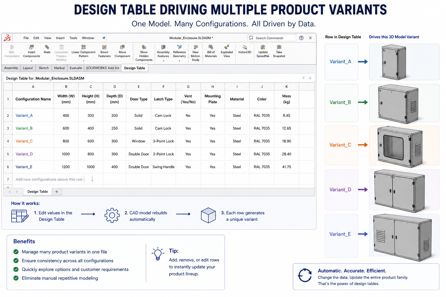
This article covers all of it. What design tables are and how they work across the major CAD platforms, where they deliver the most dramatic time savings in the development process, how to structure them for long-term maintainability, where they fail and why, and how leading engineering teams use them not just as a modeling efficiency tool but as a strategic product architecture decision.
What Design Tables Are and How They Actually Work
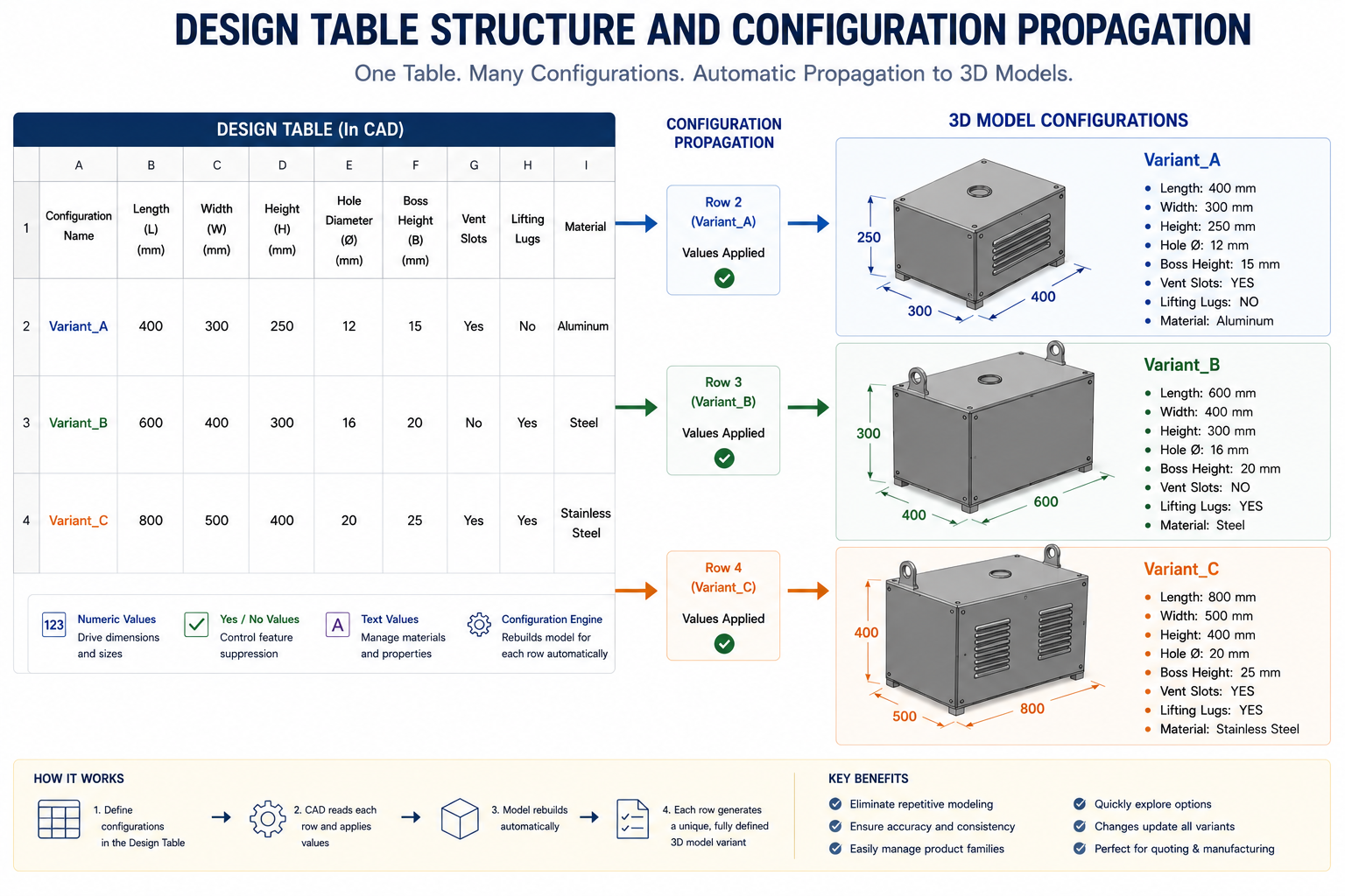
A design table is a spreadsheet-driven mechanism that controls multiple configurations of a CAD model from a single organized table. Each row in the table defines one configuration. Each column represents a dimension, parameter, feature state (suppressed or unsuppressed), or property value. Change a cell in the table, and the corresponding configuration updates automatically. Add a new row, and a new configuration is created instantly without touching the CAD model directly.
The core power of the design table is that it decouples the act of defining variants from the act of building geometry. You build the geometry once, structure it parametrically with named dimensions and configurable features, and then manage all variation through the table. The CAD model becomes a template. The design table becomes the product specification.
The Relationship Between Configurations and Design Tables
In most parametric CAD platforms, configurations are the native mechanism for storing multiple states of a model within a single file. A configuration is a saved snapshot of specific parameter values, feature suppression states, and appearance settings. Without a design table, configurations are created and managed individually through the CAD interface: right-click, add configuration, manually set each dimension, save.
A design table is a configuration manager. It does not replace configurations but drives them from a structured external or embedded spreadsheet. Every row in the design table creates, populates, and updates a configuration automatically. The result is that all your variant logic lives in a single, readable, shareable spreadsheet rather than being distributed across dozens of individual configuration dialogs inside the CAD model.
What a Design Table Actually Controls
The range of model properties that a design table can control is broader than most engineers realize. A well-structured design table can drive:
- Linear and angular dimensions: length, width, height, diameter, radius, angle, thread pitch, depth
- Feature suppression states: a boss that exists in some configurations but is absent in others, a hole pattern that appears only in certain variants
- Sketch dimension values: the spacing between holes in a bolt pattern, the offset of a groove from a reference face
- Custom properties: part number, description, material specification, finish, revision level, mass (calculated or overridden)
- Appearance and display states: color, transparency, and visual representation for each configuration
- Assembly-level component states: in assembly design tables, which components are included, suppressed, or replaced in each variant
The breadth of this control means that a single design table can fully define an entire product family, with every variant’s geometry, documentation properties, BOM line items, and visual presentation managed from one source.
| Key Concept The design table is not a shortcut for generating quick variants. It is a product architecture decision. When you commit to a design table-driven approach, you are deciding that your product variants share a common parametric structure and that the table is the authoritative source for all variation. This decision has significant downstream benefits for BOM accuracy, drawing automation, and product configurability that extend well beyond the initial time savings in modeling. |
Design Tables Across Major CAD Platforms
The design table concept exists in every major parametric CAD platform, but implementation details, capabilities, and best practices differ significantly. Understanding these differences helps you apply the approach correctly in your specific tool and helps teams that use multiple platforms understand how the concept translates across environments.
| CAD Platform | Feature Name | Driver File | Scope | Key Strength |
| SolidWorks | Design Table | Microsoft Excel (.xlsx) | Parts and assemblies | Deep Excel integration, widely used, SOLIDWORKS 2026 family tables in drawings |
| PTC Creo | Family Table | Internal Creo table editor | Parts and assemblies | Verification instances, interchange groups, no Excel dependency |
| Autodesk Inventor | iPart / iAssembly | Internal spreadsheet editor | Parts and assemblies separately | Strong BOM automation, iMate support for auto-mating variants |
| CATIA V5/V6 | Design Table | Microsoft Excel (.xls/.xlsx) | Parts, products, drawings | Supports formulas and relations driven from Excel, used in aerospace |
| Siemens NX | Spreadsheet-Driven Part | Microsoft Excel | Parts and assemblies | Integrated with Teamcenter PLM for variant BOM automation |
| Onshape | Configurations | Native table editor (cloud) | Parts and assemblies | No Excel dependency, live collaboration on configurations |
SolidWorks Design Tables: Excel Integration in Depth
SolidWorks Design Tables are embedded Microsoft Excel worksheets stored directly inside the SolidWorks part or assembly file. This integration is both the feature’s greatest strength and its primary source of problems. The Excel integration means that anyone with Excel can read, understand, and in some cases edit the table without opening SolidWorks, which is genuinely useful for collaboration between engineering and commercial teams. It also means that Excel-specific issues, formula errors, linked external file problems, and version compatibility between Excel releases, can surface inside the CAD model in ways that are difficult to diagnose.
The auto-create function in SolidWorks Design Tables will automatically populate the table with all current model dimensions when first inserted, which is convenient for getting started but produces bloated tables when the model has many non-variant dimensions. Best practice is to use the blank option and manually add only the dimensions and parameters that genuinely vary between configurations, keeping the table lean and readable.
SolidWorks 2026 introduced Family Tables for drawings, which allows all configuration details and custom properties to be displayed directly on a drawing sheet in a formatted table. This is a significant advancement that directly reduces the time cost of documentation for multi-configuration parts, one of the historically weak points of configuration-driven workflows.
PTC Creo Family Tables: The Enterprise Approach
Creo Family Tables differ from SolidWorks Design Tables in an important way: they do not depend on Microsoft Excel. The table is managed entirely within the Creo environment using an internal editor. This eliminates the Excel-related failure modes that affect SolidWorks users and makes Creo Family Tables more robust in enterprise environments where Excel version management and file linking can be problematic.
Creo Family Tables also include a verification feature that checks each instance (the Creo term for a configuration) against the model to confirm it regenerates successfully before the table is committed. This automated verification is something SolidWorks users have to perform manually, and it prevents the common problem of silently broken configurations that only reveal their failure when the engineer actually needs to use them.
Interchange groups in Creo Family Tables allow interchangeable components to be defined at the table level, which has direct applications in design-to-order manufacturing where different supplier components can be substituted within the same assembly without creating separate assembly structures.
Autodesk Inventor iParts and iAssemblies
Inventor iParts handle part-level configurations while iAssemblies handle assembly-level configurations. The separation of concern is logical but means that cross-level variant management requires careful coordination between the part and assembly tables. Inventor’s approach includes strong BOM integration, where iPart configurations automatically generate distinct BOM line items with correct part numbers and descriptions, which is a significant time saver in the documentation phase.
iMates in Inventor allow connection points to be defined on iPart variants so that when a specific configuration is placed in an assembly, the correct mating relationships are applied automatically. This feature dramatically speeds up assembly modeling when working with families of standard components like bearings, fasteners, or connectors.
Where Design Tables Deliver the Most Dramatic Time Savings
The efficiency gains from design tables are not evenly distributed across the development process. They are concentrated at specific workflow moments where the manual alternative is most time-consuming. Understanding where these moments occur helps you prioritize where to invest in design table adoption and helps you make the business case for the upfront setup time.
| Task | Without Design Table | With Design Table | Time Saved |
| Create 10 size variants of a bracket | 10 to 15 hours (rebuild each) | 1 to 2 hours (table rows) | 80 to 90% |
| Update a shared dimension across all variants | 1 to 3 hours (open each, edit, save) | Under 5 minutes (edit one cell) | 95%+ |
| Generate drawings for all configurations | 8 to 12 hours (manual per config) | 1 to 2 hours (auto-propagates) | 80 to 85% |
| Respond to customer request for new size | 1 to 3 days (new model, drawing) | Under 1 hour (add table row) | 90%+ |
| Validate all configurations rebuild correctly | Half day (open and check each) | Minutes (batch rebuild check) | 90%+ |
| Hand off to new engineer unfamiliar with variants | Days of explanation and errors | Table is self-documenting | Significant |
The Product Family Creation Scenario
The most straightforward application of design tables is building a family of related parts that differ in defined, scalable dimensions. Consider a team designing a line of aluminum extrusion brackets in lengths of 50, 75, 100, 125, and 150 millimeters, with corresponding hole pattern adjustments. Without a design table, this is five separate modeling tasks. With a design table, it is one modeling task followed by five rows in a spreadsheet.
The time savings are obvious at first glance. Less obvious is the compounding benefit: every subsequent change to the bracket design, a revised hole diameter, a different chamfer angle, a material property update, applies to all five configurations simultaneously through the shared parametric structure. The engineer makes one change in one location and every variant updates. Without the design table, the same change requires five separate file operations, each with its own risk of inconsistency or error.
The Engineering Change Scenario
Design tables deliver perhaps their clearest ROI during engineering change management. When a specification change affects a shared dimension across an entire product family, the design table reduces what would otherwise be a multi-hour manual update across many files to a single cell edit and a model rebuild.
A precision instrumentation company managing a family of forty sensor housings in different bore diameters received a material specification change that altered the minimum wall thickness for all sizes. Without design tables, updating forty individual models would have consumed most of a working day and introduced significant risk of missing a size or introducing an inconsistency. With their design table, the engineer updated a single formula in the wall thickness column, rebuilt the master model, and had all forty configurations updated and verified within an hour.
The Quotation and Custom Order Scenario
One of the least-discussed applications of design tables, and one of the most commercially valuable, is in supporting engineer-to-order and configure-to-order manufacturing. When a customer requests a custom size that sits outside the standard range, a design table makes it possible to evaluate the request, generate a model and drawing, and provide an accurate quote within hours rather than days.
The engineer adds one row to the table with the customer’s requested dimensions, rebuilds the model, generates a drawing, and checks whether any features fall outside manufacturing limits. The custom size is assessed and documented in a fraction of the time that a from-scratch model would require. If the order is placed, the configuration already exists and is ready to release. If it is not placed, removing the row from the table is the only cleanup needed.
| Commercial Impact Design tables bridge the gap between engineering and commercial functions in configure-to-order businesses. When sales can request a custom configuration and receive a validated model and drawing within the same day, rather than waiting three days for engineering to build a new model, the company’s responsiveness to customer requests becomes a genuine competitive advantage. This is a business outcome that starts with a spreadsheet in a CAD file. |
Design Tables and Drawing Automation: The Documentation Payoff
One of the biggest time costs in engineering documentation is keeping drawings current across a product family. Each configuration that requires its own drawing represents hours of dimensioning, annotation, and formatting work. Each change to the underlying model requires revisiting every affected drawing to ensure annotations still reference the correct geometry and dimensions still reflect the current values.
Design tables, when properly connected to a drawing workflow, dramatically reduce this burden.
Configuration-Driven Drawings
In SolidWorks, each drawing view can be associated with a specific model configuration. A single drawing file can contain multiple sheets, each showing a different configuration of the same part. Because each view references the configuration directly, when the design table updates a configuration, the corresponding drawing view updates automatically. The engineer does not need to manually update dimensions, because they are driven by the model parameters that the design table controls.
For a product family with ten size variants, this means a single drawing file can document all ten sizes, with views and dimension annotations updating automatically whenever the design table is revised. What previously required ten separate drawing files, each maintained individually, becomes one drawing file managed through the design table.
Property-Driven Title Blocks and BOMs
Design tables can drive custom properties in addition to geometry: part number, description, material, revision level, surface finish, and any other property that varies between configurations. When these properties are mapped to the drawing title block and linked to the BOM, the documentation chain becomes fully automated.
The engineer adds a new configuration row to the design table, including the part number and description for that variant. The model rebuilds. The drawing views update. The title block pulls the correct part number and description from the configuration’s custom properties. The BOM automatically generates the correct line items for each configuration. The entire documentation chain updates from a single spreadsheet edit, with no manual intervention required at the drawing or BOM level.
Limitations of Drawing Automation
Design table-driven drawing automation has real limits that engineers should understand before relying on it completely. Drawing annotations that are not linked to model dimensions, such as notes, callouts, and revision history, do not update automatically and require manual review after any design table change. Complex multi-sheet drawings where configurations have significantly different geometry may produce layouts where automatic view generation creates cluttered or incorrectly scaled results that require manual adjustment.
For highly regulated products where drawing release requires formal approval of every change, automated dimension updates may actually slow the review process if reviewers cannot easily identify what changed between releases. In these environments, a semi-automated approach, where design tables drive the geometry and properties but drawings are formally re-released with manual sign-off, is more appropriate than full automation.
Table-Driven Assembly Design: Beyond Individual Parts
Most tutorials on design tables focus exclusively on part-level configurations. The more powerful and more rarely documented application is assembly-level design tables, where the table controls not just dimensions but component inclusion, sub-assembly variants, and spatial relationships across an entire product structure.
Assembly Design Tables in Practice
An assembly design table follows the same principle as a part design table but operates at a higher level of the product structure. Each row defines a configuration of the assembly, which may include different component versions, suppressed or unsuppressed sub-assemblies, different positional parameters between components, and different custom properties for the assembly-level BOM.
Consider an industrial pump assembly that comes in three sizes, each of which uses a different impeller, a different casing, and different flange dimensions, but shares the same shaft, motor interface, and base mounting pattern. An assembly design table can manage all three sizes within a single assembly file: each row selects the correct configuration of the casing iPart, references the appropriate impeller component, and drives the shared interface dimensions. The entire product family lives in one assembly file with one design table, rather than in three separate assembly files that must be maintained in parallel.
The Component Suppression Power
One of the most useful capabilities in assembly design tables is the ability to suppress or unsuppress components based on configuration. A product that offers optional features, an optional cable management bracket, an optional dust shield, a handle that appears only on certain sizes, can encode those options as suppressed components in the base configuration and unsuppressed in the configurations that include them.
This approach keeps the assembly clean and the BOM accurate: suppressed components do not appear in the BOM for configurations that exclude them, so the parts list for each product variant is automatically correct without any manual editing. The engineering team can model every option once and manage their presence across all configurations entirely through the design table.
Connecting Assembly Tables to a Product Configurator
For companies that sell configurable products, a well-structured assembly design table can serve as the engineering foundation for a product configurator: a sales or customer-facing tool that allows customers to select specifications and immediately see a valid, manufacturable product configuration. The logic that determines which components are compatible, which dimensions are valid for which size ranges, and which combinations are available is embedded in the design table structure.
This connection between the engineering CAD structure and the commercial product offering is one of the highest-value applications of design tables, and it is almost entirely absent from the tutorial-level content that most engineers encounter when they first learn about design tables.
Setting Up a Design Table for Long-Term Maintainability
The upfront work of creating a design table is straightforward. Maintaining it correctly as the product evolves, as the team grows, and as the configuration count increases is where discipline and structure become critical. A poorly structured design table that works fine at ten configurations becomes a maintenance nightmare at fifty.
Structure the Table Before You Populate It
The most common mistake in design table setup is starting with an auto-generated table and then editing it reactively as configurations accumulate. This produces a table where columns are in the order they were added rather than a logical order, where column headers use internal dimension identifiers rather than readable names, and where the overall layout is understandable only to the engineer who created it.
Start with a blank table and build the column structure deliberately. Group related dimensions together: overall envelope dimensions first, then hole and feature dimensions, then material and finish properties, then custom documentation properties. Name each column with a meaningful description, not the internal dimension name that the CAD tool generates. Add a column for notes that explains what each configuration represents and any non-obvious constraints that apply to it.
Design Table Column Structure Best Practice |
Managing the Configuration Explosion Problem
Configuration explosion is the point at which the number of configurations in a design table grows beyond the team’s ability to manage them with confidence. It happens gradually: a few configurations become a dozen, a dozen become thirty, thirty become a hundred. At each stage, the engineer adding the next configuration believes the table is still manageable. The engineer who inherits it at configuration eighty-seven does not.
Prevent configuration explosion with two disciplines. First, establish a clear policy for what constitutes a valid configuration: not every theoretical combination of dimensions warrants a configuration, only those that represent actual products that will be or have been manufactured. Second, conduct periodic configuration audits to identify and remove configurations that are no longer active, that represent canceled products, or that duplicate existing configurations with trivial differences.
Design Table Ownership and Documentation
Every design table should have a designated owner who is responsible for its structural integrity, its documentation, and its governance. The owner is not necessarily the engineer who created the table, but they are the person who approves changes to the table structure, who ensures that new configurations follow the established naming convention, and who periodically audits the table for stale or incorrect entries.
Document the table outside the model as well as within it. Maintain a design table register that lists every table-driven model in the product library, the name of the owner, the number of active configurations, the date of the last audit, and any notes about special constraints or dependencies. This register is the configuration management equivalent of the CAD file register covered in file management best practices.
Design Table Failure Modes: What Goes Wrong and How to Prevent It
Design tables, like any structured system, have specific failure modes. Most of them are predictable, and most of them are preventable with the right setup discipline. Knowing them in advance is far less painful than discovering them when a configuration that a customer just ordered will not rebuild correctly.
The Excel Link Corruption Problem
SolidWorks Design Tables store the Excel worksheet inside the SolidWorks file. But many engineers configure their design tables to link to an external Excel file, thinking that this makes the table easier to edit outside the CAD environment. External Excel links are one of the most common sources of design table failures because the link breaks whenever the Excel file is moved, renamed, or opened on a machine where the path structure differs from the machine that created the link.
The symptom is a design table that opens with missing data or displays the last saved state of the table without reflecting recent Excel edits. The cure is always to embed the table rather than link externally, and to edit it through the CAD software’s design table interface rather than by opening the Excel file separately. If external access to the table is required for collaboration, export the table to Excel for review, make approved edits in the embedded version, and never rely on an external link as the primary editing mechanism.
Circular References Between Dimensions
If a design table dimension drives another dimension through an equation in the CAD model, and that second dimension is also listed as a column in the design table, a circular reference can result: the table drives a value that the equation also drives, creating a conflict about which value should win. The CAD tool handles this differently depending on the platform: some override the equation with the table value, some raise an error, and some produce inconsistent results that are difficult to diagnose.
Prevent this by maintaining a clear separation between table-driven values and equation-driven values. A dimension should be either controlled by the table or controlled by an equation, never both. Document this distinction in the table column notes and enforce it during design reviews.
Silent Configuration Failures
A configuration that was created by the design table may fail to regenerate correctly for one of several reasons: a dimension value that causes a feature to fail (a hole diameter larger than the boss it is in), a feature suppression state that is geometrically incompatible with a related feature, or a dimension value at the boundary of what the model’s constraints can accommodate. In SolidWorks, these failures are often silent: the configuration shows as available but regenerates with errors that are only visible when the configuration is activated.
Prevent silent failures by activating and inspecting every configuration after any table change, not just the one you intended to modify. In Creo, the verification feature does this automatically. In SolidWorks, you can write a macro that activates each configuration in sequence and logs any regeneration errors to a report. For a table with many configurations, this automated verification step is worth the setup time.
| Critical Practice After any design table edit, rebuild all configurations and inspect for errors before saving and checking in the file. A design table with even one silently broken configuration is a liability: it will fail at exactly the worst moment, when an engineer activates that configuration to generate a drawing or respond to a customer request. Verification takes minutes. Diagnosing a production error caused by an unverified configuration takes much longer. |
Integrating Design Tables Into the Broader Engineering Workflow
Design tables do not exist in isolation. They sit at the intersection of the CAD model, the drawing, the BOM, the PDM system, and in some organizations, the ERP system. Understanding how they connect to these adjacent systems determines how much of their potential value your team actually captures.
Design Tables and PDM: Version Control of Configurations
When a design table-driven model is managed in a PDM system, the revision control applies to the entire model file including all its configurations. A revision to the model captures the state of every configuration at that revision level, which is exactly what is needed for a coherent product history: you can retrieve the revision A model and see the exact state of all configurations as they were at revision A.
The PDM system should be configured to recognize that checking out a design table-driven model may require checking out its associated drawings as well, since the drawings reference the model configurations. Failing to check out the drawings simultaneously risks a situation where the model is revised but the drawings remain at the previous state, creating a mismatch that is especially dangerous when the drawings are what gets released to manufacturing.
Design Tables and BOM Management
Bills of materials derived from design table-driven assemblies can be either top-level BOMs that list the assembly itself with a configuration identifier, or flattened BOMs that list all components from a specific configuration. How the BOM is structured depends on how the product is sold and manufactured: a single-configuration product needs a flat BOM for that configuration, while a product that ships in multiple configurations may need a variant BOM structure that shows all configurations alongside their component differences.
PLM systems with variant management capability can consume the configuration structure from a design table-driven model and generate the appropriate BOM structure automatically, which is a significant time saver in organizations that manage large product families with many distinct configurations per assembly level.
When to Use Design Tables vs. Separate Files
Design tables are not always the right solution. There are situations where separate model files for each variant are preferable: when variants differ so fundamentally that they share almost no common geometry, when regulatory or compliance requirements mandate separate, independently controlled files for each product configuration, or when different variants will be maintained by different engineering teams with no shared update cadence.
The decision rule is: use design tables when variants share a common parametric structure and the differences between them are expressible as parameter or feature state changes. Use separate files when variants are more different than they are alike, when the maintenance and governance benefits of a shared table are outweighed by the coordination overhead it creates, or when compliance requirements mandate independent file control.
Frequently Asked Questions
Q: What is a design table in CAD and what does it do?
A design table is a spreadsheet-driven tool within a parametric CAD model that controls multiple configurations of the same part or assembly from a single organized table. Each row in the table defines one configuration by specifying the values of key dimensions, feature suppression states, and custom properties. Adding a row creates a new configuration automatically. Editing a cell updates the corresponding configuration without manually opening it. Design tables are the primary tool for managing product families and variants within a single CAD file.
Q: How much time can design tables save in product development?
The time savings depend on the number of configurations and the frequency of shared-dimension changes. For a product family with ten or more configurations, design tables typically reduce initial variant creation time by 80 to 90 percent compared to building each configuration manually. For engineering change orders that affect a shared dimension across all configurations, the savings can exceed 95 percent. The savings compound over the product lifecycle: every revision cycle is faster because the table eliminates repetitive manual work.
Q: What is the difference between a design table and configurations in SolidWorks?
Configurations are the native SolidWorks mechanism for storing multiple states of a model. A design table is a tool that creates and manages configurations through a spreadsheet interface. Without a design table, configurations are created one at a time through the configuration manager and managed individually. With a design table, all configurations are created, populated, and updated through a single spreadsheet, making it far more efficient to manage large numbers of configurations and ensuring consistency across all variants.
Q: Can design tables be used for assemblies, not just parts?
Yes, assembly design tables work the same way as part design tables but at the assembly level. They can control component inclusion and suppression states, positional parameters between components, configurations of sub-assemblies, and assembly-level custom properties. Assembly design tables are particularly powerful for products that come in multiple configurations with different component sets, because they allow the entire product family to be managed within a single assembly file rather than as separate files for each variant.
Q: What are the most common design table mistakes to avoid?
The most damaging mistakes are: linking to an external Excel file instead of embedding the table, which creates broken links when files move; creating circular references between table-driven dimensions and equation-driven dimensions; failing to verify that all configurations rebuild correctly after table edits; allowing the configuration count to grow without governance, leading to stale and broken configurations; and using internal dimension identifiers as column headers instead of readable names, making the table illegible to anyone but its creator.
Q: How do design tables work in PTC Creo compared to SolidWorks?
Creo calls the equivalent feature Family Tables, and the key difference is that Creo does not use Microsoft Excel as the table driver. The table is managed entirely within the Creo environment, which eliminates Excel-related link corruption and version compatibility issues. Creo Family Tables also include a built-in verification step that checks every instance (the Creo equivalent of a configuration) for successful regeneration before the table is committed. This automated verification prevents the silent configuration failures that can occur in SolidWorks without manual checking.
Q: How should design tables be managed in a PDM system?
Design table-driven model files should be checked into the PDM vault like any other CAD file, with version control applying to the entire file including all configurations. When checking out a design table-driven model for editing, also check out any associated drawings that reference its configurations to prevent revision mismatches. The PDM revision history should capture the complete configuration state at each revision, providing a full historical record of every variant at every design revision. Avoid editing the design table through an externally linked Excel file when using PDM, as this can create unsynchronized states between the Excel file version and the model file version.
Conclusion:
Design tables represent one of the clearest examples of the principle that the best way to save time in engineering is to invest it in structure upfront. Building a parametric model with a well-governed design table takes longer than building a single standalone part. It takes far less time than building, maintaining, and updating ten separate models individually over the life of a product.
The engineers and teams that use design tables most effectively are not just using them as a modeling shortcut. They are using them as a product architecture decision: a deliberate choice to encode the logic of their product family in a structured, maintainable, auditable form that pays dividends throughout the entire development cycle, from initial configuration creation through engineering changes, drawing generation, BOM management, customer quotation, and product lifecycle maintenance.
If your team currently builds and maintains product variants as separate files with manual updates, the path to design tables starts with a single model. Pick the product family with the most variants. Build one parametric master model with named dimensions. Add a design table. Create two configurations. Check that both rebuild correctly. Then scale.
The first design table you build will take longer than your current approach. The second will be faster. The tenth will feel effortless, and your product family will be more consistent, more maintainable, and more responsive to change than it has ever been.
Ready to build a complete, efficient CAD workflow? Explore our guides on parametric modeling best practices, design intent in CAD, CAD file management, and reducing rework through better model structure.
Leave a Reply