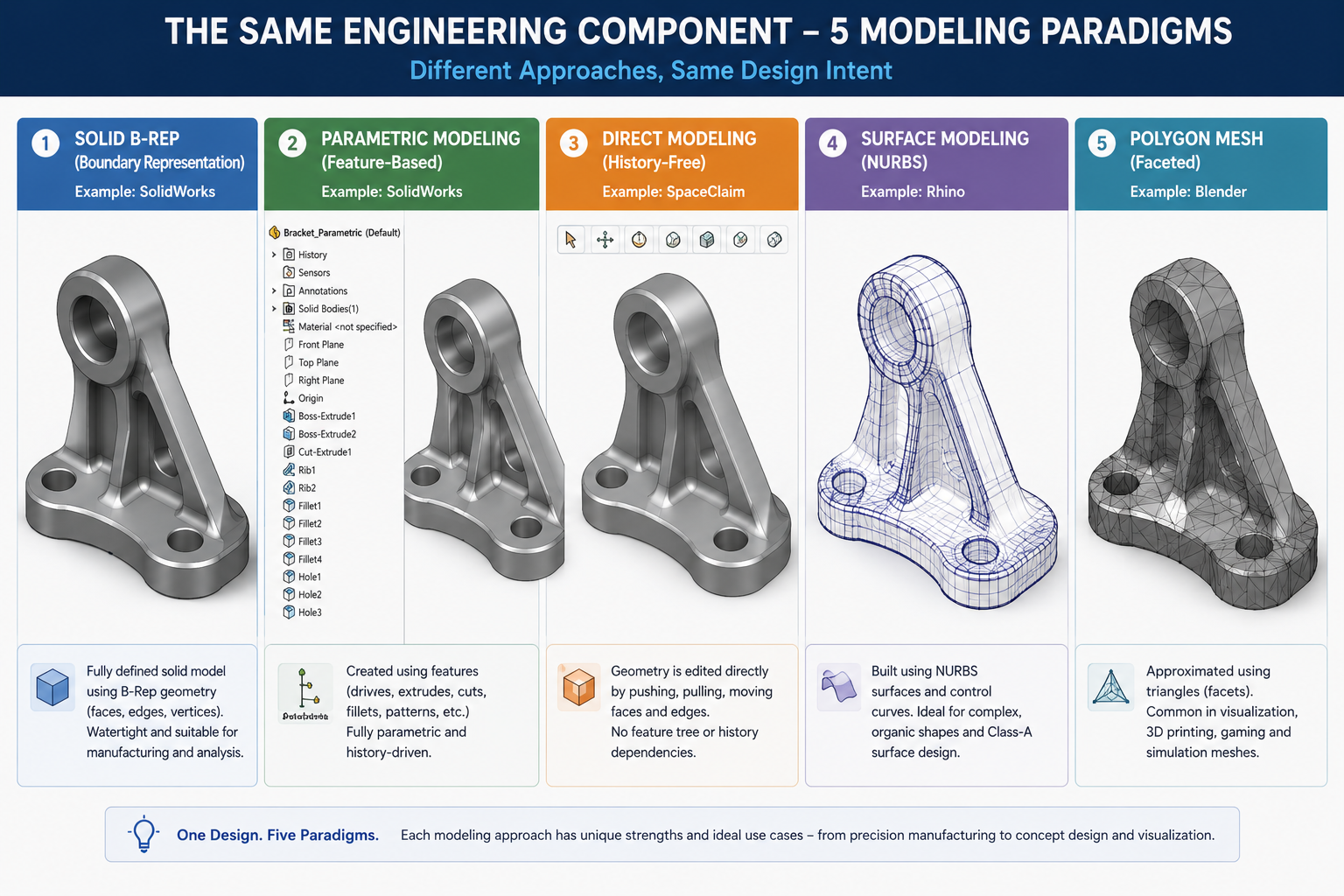
3D modeling in CAD is the technical discipline at the heart of modern engineering and design. Every car that drives, every aircraft that flies, every medical device that saves a life, and every building that stands was first created as a precise 3D digital model before a single physical component was manufactured or a foundation was dug. The 3D CAD model is where engineering creativity becomes engineering reality.
Yet despite its central importance, 3D modelling in CAD is one of the least well-explained topics in engineering education. Most tutorials cover how to use a specific tool’s commands. Very few explain what is actually happening mathematically when you extrude a profile, why parametric modelling works the way it does, when surface modelling is the right approach versus solid modelling, how to plan a model structure so it remains editable under future design changes, or how to validate a 3D model before releasing it for manufacture.
This pillar guide closes all of those gaps. It covers 3D modelling in CAD from first principles through to advanced professional practice: the five modelling paradigms and their underlying mathematics, the complete 3D modelling workflow from concept to verified model, assembly modelling and large assembly management, advanced techniques including topology optimisation and generative design, industry-specific workflows across six engineering disciplines, model quality and validation, the best tools for each type of 3D modelling work, the integration of 3D models with simulation and manufacturing, and the AI-driven changes reshaping the discipline in 2026.
| Quick Definition: 3D modeling in CAD is the process of creating a complete three-dimensional digital representation of a physical object or system using computer-aided design software. The resulting 3D model defines the object’s geometry with engineering precision, it can be measured, analysed, modified, used to generate manufacturing instructions, and used as the basis for structural or fluid dynamic simulation. It is the primary method by which engineering designs are created, communicated, and verified in the modern engineering profession. |
What Is 3D Modeling in CAD? Foundations and Purpose
3D modeling in CAD is the creation of a mathematically defined three-dimensional digital object within a computer-aided design software environment. Unlike a 2D drawing, which represents an object through multiple flat views and relies on the reader to reconstruct the 3D form mentally, a 3D CAD model is a complete, unambiguous representation of the object that exists in three-dimensional coordinate space with exact geometric definition.
The fundamental difference between a 3D CAD model and a 3D model created in general-purpose software (such as Blender or 3D Studio Max for visual effects) is engineering precision. A 3D CAD model is defined in real-world measurement units (millimetres, inches, metres) with exact dimensional values. Every face, edge, and vertex has a precise mathematical location in the coordinate system. The model can be interrogated to return mass, volume, centre of gravity, moments of inertia, and surface area, properties that are essential for engineering analysis.
Why 3D Modeling Changed Engineering Practice
Before 3D CAD modeling became mainstream in the 1990s, engineers designed products entirely in 2D: producing multiple orthographic views of each component and mentally synthesising them into an understanding of the 3D form. This process was slow, error-prone (particularly for complex geometry), and made it extremely difficult to detect interference between components in an assembly before physical prototypes were built.
The introduction of parametric 3D solid modelling, pioneered by Pro/ENGINEER in 1987 and brought to the mass market by SolidWorks in 1995, transformed this workflow. Engineers could now design in 3D directly, visualise the product from any angle, detect clashes automatically, generate all 2D views simultaneously from the single 3D master model, and hand the model directly to simulation software for analysis and to CAM software for manufacturing programming.
According to Aberdeen Group research, companies that use 3D CAD modeling reduce time-to-market by an average of 50 percent compared to 2D design workflows, reduce manufacturing errors by 65 percent, and reduce the cost of design changes by up to 90 percent when changes are made in the 3D model rather than after physical production.
| Benefit of 3D CAD Modeling | Specific Advantage | Industry Impact |
| Spatial visualisation | Design can be viewed from any angle, rotated, sectioned, and animated | Dramatically reduces interpretation errors between designers and manufacturers |
| Automatic 2D drawing generation | Orthographic views, sections, and details generated automatically from the 3D model | Eliminates the manual drawing board workflow; drawing updates automatically when model changes |
| Interference and clash detection | Software automatically identifies where two components physically overlap in an assembly | Prevents manufacturing of components that cannot be assembled, historically discovered only at first physical build |
| Mass properties calculation | Weight, centre of gravity, moments of inertia calculated directly from the solid model geometry | Enables structural analysis, balance calculations, and manufacturing cost estimation without physical prototypes |
| Simulation input | 3D geometry used directly as input for FEA stress analysis, CFD, and thermal simulation | Reduces physical prototype testing cycles; finds structural or thermal issues before manufacture |
| Manufacturing programming | CNC toolpaths generated directly from the 3D model surface geometry | Eliminates manual programming for complex 3D machined surfaces; reduces errors in manufacturing instructions |
| Product visualisation and rendering | Photorealistic images and animations produced before physical product exists | Enables client approval and marketing before tooling investment |
The Five 3D Modeling Paradigms Explained
3D modeling in CAD is not a single methodology. It encompasses five distinct paradigms, each based on different mathematical representations of geometry and each suited to different design tasks. Understanding all five, and knowing when to apply each, is what separates a proficient 3D modeller from an expert one.
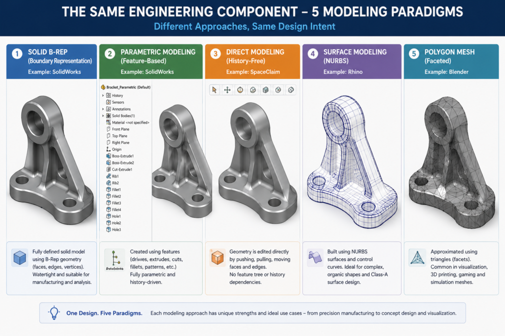
| Paradigm | Mathematical Foundation | Primary Strength | Primary Limitation | Best Application |
| Solid Modeling (B-rep) | Boundary Representation: solid defined by closed set of faces, edges, vertices | Physically complete, mass properties calculable, FEA-ready, Boolean operations | Less suited to organic free-form shapes | Mechanical engineering, product design, any manufactured component |
| Parametric Feature-Based | Feature history tree + constraint solving on top of B-rep geometry | Design intent preserved, intelligent model updates, family-of-parts design | Requires careful model structure planning; edit order matters | Production mechanical design, repeated design families, any design requiring multiple iterations |
| Direct (Explicit) Modeling | Direct geometry manipulation of B-rep without stored history | Fast, flexible, works on imported geometry with no feature tree | No design intent stored; changes do not propagate intelligently | Concept modelling, imported geometry repair, simulation model preparation |
| Surface Modeling (NURBS) | Non-Uniform Rational B-Splines: surfaces defined by control points and weights | Perfect curvature control, Class A surfaces, complex organic shapes | Surfaces must be manually stitched; steeper learning curve | Automotive styling, aerospace aerodynamics, premium consumer products |
| Mesh / Polygon Modeling | Triangulated or quadrilateral polygon mesh approximating surface | Handles complex organic shapes, fast for visualisation, 3D printing compatible | Not dimensionally precise; not manufacturing-ready without conversion | 3D printing, visual rendering, scan-to-CAD, game assets, organic forms |
Paradigm 1: Solid Modeling (B-rep)
Solid modeling using Boundary Representation (B-rep) is the foundational paradigm of engineering CAD. A B-rep solid is a complete, closed, watertight volumetric object defined by the mathematical surfaces that bound it, faces, edges (where faces meet), and vertices (where edges meet). The geometric kernel (Parasolid or ACIS in most commercial tools) maintains the topological relationships between all these elements to ensure the model is always a valid, manifold solid.
What B-rep Solid Modeling Enables
The completeness of the B-rep representation, the fact that the solid is fully enclosed with no gaps or self-intersections, is what enables mass properties calculation (the kernel can integrate over the enclosed volume to compute mass, centre of gravity, and inertia tensor), Boolean operations (precisely cutting one solid from another using the mathematical intersection of their boundary surfaces), and automatic generation of 2D section views (cutting the solid with a plane to produce a precise cross-sectional profile).
Boolean Operations in Solid Modeling
The three fundamental Boolean operations in solid modeling are mathematically equivalent to set operations applied to the volumetric regions bounded by the solids:
- Union (A U B): Creates a new solid that encloses all points inside either solid A or solid B. Used to combine separate solid features into one body.
- Intersection (A n B): Creates a new solid that encloses only points inside both solid A and solid B simultaneously. Used to find the overlapping volume of two solids.
- Difference (A – B): Creates a new solid that encloses points inside solid A but not inside solid B. This is the mathematical foundation of the SUBTRACT command, cutting a hole, pocket, or channel.
| Engineering Context: When an engineer subtracts a cylinder from a box to create a hole, the CAD software is computing the set difference A – B between the B-rep solid of the box and the B-rep solid of the cylinder, then rebuilding the resulting boundary surface topology. This is why the hole has perfectly cylindrical interior walls that are tangent to the box faces, the result is geometrically exact, not an approximation. |
Paradigm 2: Parametric Feature-Based Modeling
Parametric feature-based modeling extends B-rep solid modeling by adding two critical layers: a feature history that records the sequence of operations used to build the model, and a constraint system that maintains the geometric relationships between elements. Together, these layers encode the engineer’s design intent, the rules that govern how the model should change when parameters are modified.
The Feature History Tree
The feature tree (model tree or design tree) is a chronological record of every operation applied to the model. It might read: Base Extrusion > Fillet > Through Hole > Hole Pattern > Chamfer > Thread. Each entry in the feature tree is a parametric feature, an operation defined not just by the geometry it produces but by the parameters that govern it (extrusion depth, fillet radius, hole diameter, pattern count and spacing).
When a parameter is changed, for example, the extrusion depth is increased from 50mm to 75mm, the CAD system rebuilds the model from that feature downward in the feature tree. The fillet, hole, pattern, chamfer, and thread all update automatically, because they are defined relative to the base extrusion geometry that has just changed. This automatic propagation is design intent in action: the engineer specified that the fillet is on the top edge of the base extrusion, so wherever the top edge goes, the fillet follows.
Sketches and 2D Profiles as Parametric Foundations
Most parametric features begin with a 2D sketch, a constrained 2D profile drawn on a reference plane or an existing face. Sketches contain geometric constraints (horizontal, vertical, coincident, tangent, perpendicular) and dimensional constraints (length = 100mm, angle = 45 degrees). When the sketch is fully constrained, it has no remaining degrees of freedom: every point is exactly located.
The rule for healthy parametric models is: always work from fully constrained sketches. An under-constrained sketch has degrees of freedom, elements can move in unintended ways when other parameters change. An over-constrained sketch has conflicting constraints and will fail to rebuild. Fully constrained sketches rebuild predictably and make the model robust to design changes.
Model Planning: The Forgotten Skill in Parametric Modeling
The most important and least taught skill in parametric 3D modeling is model planning, deciding the structure of the feature tree before building a single feature. The sequence in which features are created determines how the model can be edited later. A poorly planned feature tree can become rigid and fragile: changing a fundamental parameter causes dozens of downstream feature failures. A well-planned feature tree is resilient: any reasonable design change updates predictably with zero failures.
| Model Planning Principle | What It Means | Why It Matters |
| Start with the dominant form | Create the primary shape that defines most of the component’s volume first | All subsequent features reference the base, if the base is wrong, everything is wrong |
| Use symmetry features | Mirror geometry about symmetry planes rather than modelling each half separately | Symmetric changes (fillet radius, pocket depth) update on both sides automatically |
| Parametrise key dimensions | Link related dimensions through equations or global variables | Changing one dimension updates all related dimensions consistently, eliminates inconsistency errors |
| Group related features | Place functionally related features (all holes in a bolt circle, all cosmetic chamfers) close together in the tree | Makes the tree readable and makes design changes easier to locate and apply |
| Avoid circular references | Never reference a feature’s own output as its input | Circular references cause rebuild failures and are extremely difficult to diagnose |
| Use design tables for families | Define multiple configurations of a part using a spreadsheet-driven design table | Allows one model to represent all sizes in a component family without separate files |
Paradigm 3: Direct (Explicit) Modeling
Direct modeling (also called explicit modeling or history-free modeling) manipulates 3D geometry directly, pushing faces, pulling edges, adjusting surfaces, without a parametric feature history constraining those manipulations. The CAD system operates on the current state of the B-rep geometry rather than on a recorded history of how it was built.
When Direct Modeling Is the Right Approach
Direct modeling is not a simpler or less capable alternative to parametric modeling, it is a different paradigm suited to different tasks. The two situations where direct modeling is clearly superior:
- Working with imported geometry: Files from other CAD systems arrive as ‘dumb’ B-rep solids with no feature history. Direct modeling tools (Ansys SpaceClaim, Fusion 360 direct mode) allow efficient modification of this imported geometry, removing fillets for FEA simulation, simplifying holes, adjusting features, without needing to rebuild the model parametrically.
- Early-stage concept exploration: When the design is still in flux and the engineer needs to explore forms quickly without being constrained by a parametric feature structure, direct modeling allows rapid shape exploration without the overhead of maintaining feature tree integrity.
| Task | Parametric Modeling | Direct Modeling |
| Rapid early concept exploration | Slower, feature tree requires upfront planning | Faster, push/pull any face immediately |
| Repeated design iterations on production parts | Superior, parameters update entire model intelligently | Limited, each change is independent, no propagation |
| Working with imported STEP files | Fails, no feature history to reference | Ideal, operates directly on B-rep without needing history |
| Preparing simulation geometry | Inefficient, parametric changes to simplify model require feature understanding | Ideal, SpaceClaim and similar tools optimised for this task |
| Family of parts (multiple sizes) | Superior, design tables, configurations | Not suitable, each variant requires manual recreation |
| Concept modelling / form exploration | Acceptable but constrained | Superior, maximum geometric freedom |
Paradigm 4: Surface Modeling (NURBS)
Surface modeling represents 3D geometry as a collection of smooth mathematical surfaces rather than as a closed volumetric solid. Where solid modeling is the CAD equivalent of sculpting a clay block, surface modeling is the CAD equivalent of working with sheets of flexible material, bending, stretching, and joining them to create the desired exterior form.
NURBS Mathematics Explained Accessibly
NURBS (Non-Uniform Rational B-Splines) are the mathematical foundation of professional surface modeling. A NURBS curve is defined by a set of control points and weights, the curve is attracted toward each control point with a strength proportional to its weight. Moving a control point changes the curve shape smoothly across a region, not just at a single point.
NURBS surfaces extend this to two dimensions: a grid of control points in (u, v) parameter space defines a smooth surface in 3D coordinate space. The mathematical properties of NURBS ensure that the resulting surface is smooth to any required degree of continuity, can represent exact conic sections (circles, ellipses) as well as complex free-form shapes, and can be evaluated at any parameter value to return the exact 3D point, tangent vector, and normal vector at that location.
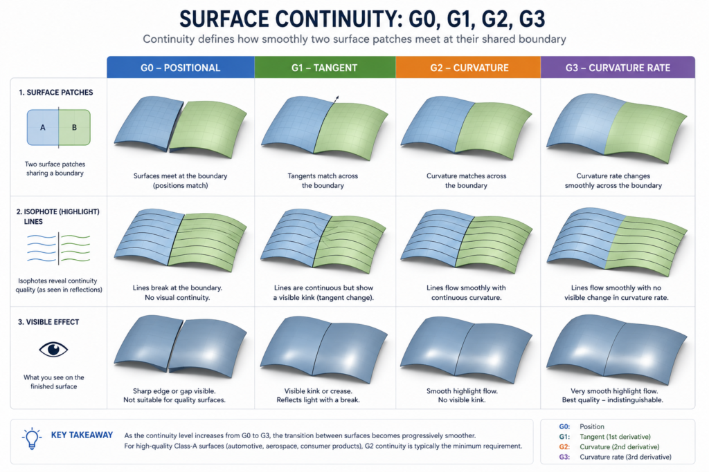
Surface Continuity: G0, G1, G2, G3
The most important concept in professional surface modeling is surface continuity, the smoothness with which two adjacent surface patches meet at their shared boundary. Continuity is classified by degree:
| Continuity Grade | What It Means | Visual Test | Where Required |
| G0 (Position continuity) | The surfaces meet with no gap, they share the same boundary curve | No visible gap | Minimum requirement for any watertight model, gaps are structural failures |
| G1 (Tangent continuity) | The surfaces share the same tangent direction at the boundary, they meet without a visible angle kink | No sharp edge at boundary | Most manufacturing surfaces; visible joins without sharp creases |
| G2 (Curvature continuity) | The surfaces share the same curvature at the boundary, rate of direction change is identical on both sides of the join | Reflection lines flow smoothly across boundary | Required for automotive body panels and any surface judged by reflection quality |
| G3 (Curvature rate of change) | The rate of change of curvature is also matched, the smoothest mathematically achievable join | No visible disturbance in highlight lines even under point light sources | Premium consumer products, aerospace intake geometries, highest-quality automotive |
| Why Continuity Matters in Manufacturing: On an automotive body panel, a G1 boundary (tangent but not curvature-continuous) creates a highlight line distortion, a subtle but visible kink in the reflection of light across the surface. Under direct sunlight or in a showroom, this defect is immediately visible to the eye and is unacceptable on a premium vehicle. Class A surfacing requires G2 continuity at all joins as an absolute minimum standard. The environmental reflection test, viewing the model under a simulated lined environment (isophotes), is the standard method for detecting continuity violations. |
Paradigm 5: Mesh and Polygon Modeling
Mesh modeling represents 3D surfaces as a network of flat polygonal faces, typically triangles or quadrilaterals, that approximate the desired surface. Unlike NURBS (which defines surfaces mathematically exactly) or B-rep (which defines solids precisely), a mesh model is an approximation: the more polygons (higher polygon count), the smoother and more accurate the approximation, at the cost of larger file size and slower processing.
When Mesh Modeling Is Used in Engineering
- 3D printing and additive manufacturing: STL format (the universal 3D printing format) is a triangulated mesh. All 3D printing workflows convert solid or surface models to mesh for slicing and printing.
- Reverse engineering (scan-to-CAD): Structured light or laser scanners produce point clouds that are converted to polygon meshes. Engineers work with these scan meshes to create reference geometry for redesign.
- FEA mesh generation: FEA solvers internally convert B-rep solid geometry to finite element meshes for the solver. The mesh quality (element size, aspect ratio) directly affects simulation accuracy.
- Organic and sculptural design: Forms that are difficult to define parametrically (shoe soles, ergonomic grip surfaces, character models, terrain) are efficiently modelled as subdivision surface meshes.
- Visualisation and rendering: All real-time 3D rendering (game engines, VR, interactive visualisation) uses polygon meshes, the GPU renders triangles, not mathematical surfaces.
| Mesh vs Solid for Manufacturing: Mesh models are not dimensionally accurate, they are approximations of the true geometry. For manufacturing inspection purposes, a solid B-rep model defines tolerances exactly. A mesh model printed on a 3D printer will reproduce the faceted approximation, not the mathematically exact surface. For high-precision manufactured components, always start from B-rep solid or NURBS surface geometry and convert to mesh only as the final output step for the specific application (printing, rendering, FEA) that requires it. |
The Mathematics Behind 3D CAD Modeling
Understanding the mathematical foundations of 3D CAD modeling is not required to use CAD software productively, but it is what separates engineers who use CAD intuitively from those who understand it fundamentally. The following concepts underpin everything that happens when a 3D model is created, modified, and analysed.
Coordinate Systems and Vectors
Every point in a 3D CAD model is defined by three coordinates (x, y, z) in a Cartesian coordinate system. Directions and orientations are represented as unit vectors, vectors of magnitude 1 pointing in the direction of interest. The surface normal vector at any point on a face, the axis of a cylindrical feature, and the direction of gravity for mass properties calculations are all unit vectors.
Coordinate transformations (rotations, translations, scales) are represented as 4×4 transformation matrices in homogeneous coordinates. When you move an assembly component, rotate a sketch plane, or define a User Coordinate System, the CAD kernel applies a transformation matrix to convert between coordinate frames. Understanding this explains why the order of transformations matters (rotation then translation produces a different result from translation then rotation) and why the UCS must be set correctly before drawing.
Geometric Tolerancing in 3D Models: GD&T
Geometric Dimensioning and Tolerancing (GD&T) is the engineering language for defining the permitted variation in manufactured geometry. In modern 3D modeling practice, GD&T is increasingly applied directly to the 3D model as 3D annotations (also called Product Manufacturing Information, PMI) rather than only to 2D drawings. The ASME Y14.5 and ISO 1101 standards define the complete GD&T symbol set, including:
- Form tolerances: Flatness, straightness, circularity, cylindricity, controlling the shape of individual features
- Orientation tolerances: Angularity, perpendicularity, parallelism, controlling the angle of features relative to datum references
- Location tolerances: True position, concentricity, symmetry, controlling where a feature is relative to datum references
- Profile tolerances: Profile of a line, profile of a surface, controlling the form, orientation, and location of complex surfaces simultaneously
- Runout tolerances: Circular runout, total runout, controlling the variation of rotating surfaces relative to a datum axis
The Complete 3D Modeling Workflow: From Concept to Verified Model
Professional 3D CAD modeling follows a structured workflow that ensures the model is correct, complete, and usable for its intended purpose. Skipping stages in this workflow is the most common cause of models that look right visually but fail in manufacturing, assembly, or simulation.
| Stage | Activity | Key Questions to Answer | Outputs | Common Mistakes |
| 1. Requirements capture | Understand what the model must achieve: function, manufacturing process, assembly context, tolerances | What is this part for? How is it made? What does it connect to? What are the critical dimensions? | Requirements list, envelope drawing, reference geometry | Starting to model without understanding manufacturing process or assembly context |
| 2. Concept sketching | Rough 2D sketches or direct-mode 3D exploration to establish overall form | What is the simplest shape that meets requirements? Where are the key features? | Concept sketches, rough 3D forms | Over-detailing at concept stage, spend time on concept, not detail |
| 3. Model planning | Decide the feature tree structure before building anything | What is the base feature? What references what? Where is the symmetry? What parameters will change? | Feature tree plan, parameter list, sketch plane decisions | Skipping this stage, leads to fragile models that fail under design changes |
| 4. Base feature creation | Build the dominant 3D form using EXTRUDE or REVOLVE from a fully constrained sketch | Is the sketch fully constrained? Does the extrusion depth come from a reference dimension? | Base solid or surface body | Under-constrained sketches that drift when other features change |
| 5. Secondary features | Add form-defining features: additional extrusions, cuts, revolves, lofts, sweeps | Does each new feature reference the correct geometry? Are all sketches fully constrained? | Complex solid form | Referencing geometry that might be removed or modified, fragile parent-child relationships |
| 6. Detail features | Add manufacturing details: fillets, chamfers, threads, knurls, text | Are fillet radii from the drawing? Are threads the correct standard size? | Fully detailed solid | Adding fillets too early, they complicate subsequent features and can cause rebuild failures |
| 7. Model verification | Check geometry quality, mass properties, feature rebuild success | Does the model rebuild cleanly? Are mass properties reasonable? Are there any geometric errors? | Verified model with mass properties report | Releasing a model without verification, geometry errors discovered in manufacturing are very expensive |
| 8. Documentation | Generate 2D drawings, 3D PMI annotations, BOM entries | Are all critical dimensions shown? Is GD&T complete? Is the BOM linked to the correct part numbers? | Engineering drawings, 3D annotated model, BOM | Drawing dimensions that disagree with model, always dimension from the model, not manually |
Assembly Modeling and Large Assembly Management
Assembly modeling in CAD places multiple individual part models into a common coordinate space, defines the geometric relationships between them (mates or constraints), and allows the assembled system to be visualised, analysed for interference, and used to generate assembly documentation.
Assembly Mates and Constraints
The geometric relationships between parts in an assembly are defined by mates (SolidWorks) or assembly constraints (CATIA/NX/Inventor). Common mate types include:
- Coincident: Two planar faces share the same infinite plane. The most commonly used mate.
- Concentric: Two cylindrical or conical faces share the same axis. Used for aligning holes with bolts, shafts with bores.
- Distance: Two planar faces maintain a specified distance between them, a gap between parts.
- Angle: Two planar faces maintain a specified angle relative to each other, for hinged or angled joints.
- Tangent: A curved surface is tangent to a plane or another curved surface.
- Gear / Rack-and-Pinion / Screw: Kinematic mates that define the mechanical relationship between moving components.
Large Assembly Management
Large assemblies, those containing hundreds or thousands of components, place significant demands on CAD system performance. Most CAD tools provide specific large assembly management strategies:
| Strategy | What It Does | When to Use | Available In |
| Lightweight components | Loads only the visual representation (shell geometry) of components rather than full parametric data | When reviewing or documenting an assembly without needing to edit individual parts | SolidWorks, CATIA, NX, Inventor |
| SpeedPak (SolidWorks) | Creates a simplified configuration of an assembly with only the outer faces visible, dramatically reduces memory | When referencing a supplier assembly in your design and only need its external envelope | SolidWorks |
| Level of Detail (LOD) representations | Stores multiple assembly configurations at different detail levels (full, simplified, bounding box) | Large assemblies viewed at different zoom levels or in different design contexts | CATIA, NX |
| Envelope components | Replaces a sub-assembly with a simplified box or shape representing its space claim | Early design stages when exact sub-assembly geometry is not needed | All major parametric CAD tools |
| Out-of-context editing | Opens and edits individual components within the assembly context without loading the full assembly | Editing a part while being able to reference neighbouring components for fit | SolidWorks, Inventor |
| Assembly sectioning | Cuts through the assembly with a section plane to inspect internal fit without disassembling | Checking bore-shaft fits, seal groove geometry, internal component clearances | All major CAD tools |
Advanced 3D Modeling Techniques
Topology Optimisation
Topology optimisation is a numerical optimisation technique that determines the optimal material distribution within a defined design space for a given set of loading conditions, boundary conditions, and performance objectives. Starting from a solid block filling the maximum allowable volume, the algorithm iteratively removes material from regions where stress is low (material that is not contributing significantly to carrying the applied loads) until a target mass reduction or stiffness target is achieved.
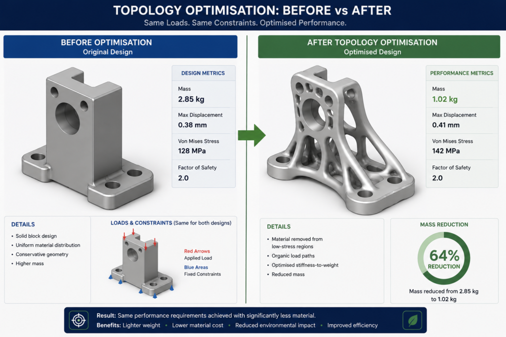
The results of topology optimisation are characteristically organic and lattice-like, the algorithm produces structures that look biologically inspired because they follow the same efficiency principles that evolution applies to natural load-bearing structures. Modern CAD tools including SolidWorks Topology Study, Fusion 360 Generative Design, ANSYS Topology, and nTop provide integrated topology optimisation. The resulting geometries are typically manufacturable only by additive manufacturing (3D printing) or casting, as they have internal voids and organic surfaces that cannot be machined.
Lattice Structures and Infill Design
Lattice structures are internal geometric architectures that provide structural support with significantly lower mass than solid material. They are particularly relevant to additive manufacturing, where internal lattice infill can be printed within a solid outer shell to reduce part weight while maintaining structural integrity.
Tools including nTop (nTopology), Materialise Magics, and Autodesk Netfabb provide dedicated lattice design capabilities. Lattice parameters including cell size, strut diameter, and topology (body-centred cubic, face-centred cubic, octet truss) can be varied across the part volume based on the local stress distribution from an FEA result, placing denser lattice where stresses are high and lighter lattice where they are low.
Multi-Body Solid Modeling
Multi-body solid modeling allows a single part file to contain multiple separate solid bodies that can be designed together in context before being split into individual part files. This is particularly useful for designing parts that are machined from a common blank, parts that are cast together and then separated, and parts that must be designed together for fit but are separate manufactured components.
Freeform Surface Sculpting (T-Splines)
T-Splines are a hybrid surface technology that combines the smooth continuity of NURBS surfaces with the flexibility of polygon subdivision surfaces. They allow organic, sculptural forms to be created by pushing and pulling control points (like mesh modeling) while maintaining smooth NURBS-quality surfaces. Fusion 360’s Form workspace uses T-Splines for organic design, allowing engineers and designers to create ergonomic product shapes that are then converted to B-rep solids for analysis and manufacturing.
Industry-Specific 3D Modeling Workflows
| Industry | Primary Modeling Paradigm | Key Workflow Characteristics | Critical Modeling Requirements | Primary Tools |
| Mechanical Engineering (product design) | Parametric feature-based solid modeling | Part file -> Assembly -> Drawing. Design tables for variants. Sheet metal and weldment specialists. | Fully constrained sketches, correct feature order, design intent encoded, GD&T annotations | SolidWorks, CATIA, NX, Creo, Inventor |
| Aerospace Structures | Parametric solid + surface modeling, FEA-driven | Aerostructure geometry from external aerodynamic surfaces. Composite layup definition. Weight-criticality drives topology optimisation. | Class A surfaces for aerodynamic surfaces. Accurate material properties for FEA. Manufacturing process (RTM, AFP) constraints. | CATIA, NX, SolidWorks, ANSYS |
| Automotive Body Design | Class A surface modeling, then solid modeling | Exterior styled surfaces (Class A) created first by stylists, then structured into engineering solid geometry by CAE engineers. | G2 or G3 continuity at all surface joins. Manufacturing feasibility (stamp formability). Panel split line definition. | CATIA (surface styling), Alias (surfacing), NX (engineering) |
| Architecture and Construction (BIM) | Parametric object-based BIM | Building objects (walls, slabs, beams) rather than pure geometry. Multi-discipline coordination in federated model. | Object data completeness (material, fire rating, structural properties). IFC export compliance. Coordination with MEP, structure. | Revit, ArchiCAD, Allplan, Vectorworks |
| Consumer Product Design | Direct modeling + parametric + surface + rendering | Form-driven design. Ergonomics. Brand language. Manufacturability (injection moulding, thermoforming). | Parting lines for moulding. Draft angles. Wall thickness uniformity. CMF (colour, material, finish) definition. | Fusion 360, SolidWorks, Rhino (form exploration), KeyShot (rendering) |
| Medical Device Engineering | Parametric solid + FEA + biocompatibility verification | Extreme dimensional precision. Regulatory (FDA, MDR) traceability. Sterile packaging consideration. Human anatomy interface. | Tolerances matched to manufacturing capability. Material biocompatibility data in model metadata. Verification and validation documentation. | SolidWorks, CATIA, NX, ANSYS |
3D Model Quality, Validation, and Release
A 3D model is only as valuable as it is accurate. Releasing a model with geometry errors, non-manifold topology, or incorrect mass properties can cause manufacturing failures, assembly problems, or simulation inaccuracies that cost orders of magnitude more to fix than the original modeling error. Systematic model quality checks before release are not optional, they are a professional obligation.
Geometric Quality Checks
- Check for zero-thickness geometry: Faces with zero area or edges with zero length indicate degenerate geometry that will cause problems in downstream processes.
- Check for non-manifold geometry: A manifold solid has exactly two faces meeting at every edge. Non-manifold geometry (more than two faces at an edge, or T-intersections) indicates a topologically invalid solid.
- Check for self-intersecting faces: Faces that cross each other within the model create regions of ambiguous inside/outside, the solid is undefined in those regions.
- Check watertightness: The model should have no gaps between faces. Any gap means the solid is not enclosed, mass properties will be wrong and manufacturing outputs will be unreliable.
- Verify rebuild success: Force a complete rebuild (Edit > Rebuild All in most parametric tools) and confirm zero errors in the feature tree.
Mass Properties Verification
After building any new model, always calculate mass properties (mass, volume, centre of gravity, moments of inertia) and perform a sanity check. Estimate the expected mass based on the material density and approximate volume before running the calculation. If the calculated mass differs by more than a few percent from the estimate, investigate why, common causes include incorrect material assignment, double-counting of solid bodies, or a geometry error that has inflated or deflated the enclosed volume.
Design Review Checklist Before Model Release
| Check | Method | Pass Criterion |
| Feature tree rebuilds cleanly | Force Rebuild All (Ctrl + Q in SolidWorks) | Zero errors and zero warnings in feature tree |
| Model is fully constrained | Check sketch status, all sketches show as fully defined | No under-defined or over-defined sketches |
| Mass properties verified | Evaluate > Mass Properties | Mass within 5% of hand-calculated estimate using material density x volume |
| Interference check passed | Evaluate > Interference Detection (for assemblies) | Zero interferences between components in assembly |
| Critical dimensions verified | Smart Dimension check on key features | All critical dimensions match the engineering requirement exactly |
| GD&T annotations complete | Review 3D annotation tree or drawing annotation | All toleranced features have GD&T callouts; all datums defined |
| File saved in correct format | File > Save As (check format and version) | Saved in company standard format (native + STEP for neutral exchange) |
| Model checked in to PDM | PDM/PLM check-in workflow | Model stored under version control, not in local working copy only |
3D CAD Model Integration with Simulation and Manufacturing
From 3D Model to FEA Simulation
The path from a 3D CAD model to a Finite Element Analysis (FEA) simulation involves several preparation steps that directly affect simulation accuracy and reliability. Many engineers skip these steps and wonder why their simulation results are unreliable or why the mesher fails on their geometry.
- Geometry simplification: Remove cosmetic features (logos, decorative chamfers, very small fillets) that do not affect structural behaviour but create problematic small elements in the FEA mesh. SpaceClaim, Fusion 360’s simplify tools, and the ANSYS SpaceClaim integration are designed for this.
- Defeaturing: Remove irrelevant features (thread geometry, knurling, fine surface texture) that add mesh complexity without contributing to the structural result. A bolt hole of diameter 8mm does not need the thread helix modelled for a linear static analysis.
- Assign materials: Assign correct material properties (Young’s modulus, Poisson’s ratio, density, yield strength) from validated material databases. Material assignment errors are one of the most common sources of incorrect FEA results.
- Define boundary conditions: Apply loads (forces, pressures, thermal loads) and constraints (fixed faces, symmetry planes) that represent the real-world operating condition being analysed.
- Mesh and solve: The FEA solver meshes the geometry and solves the governing equations. Review mesh quality metrics (aspect ratio, Jacobian) before accepting results.
From 3D Model to CNC Manufacturing
The path from a 3D CAD model to CNC machined part involves the CAM (Computer-Aided Manufacturing) workflow. The 3D solid model defines the finished part geometry; the CAM system generates the toolpaths that cut away material from a blank workpiece to leave the desired form.
- Import model: Load the 3D solid model into the CAM environment. Fusion 360 integrates CAD and CAM; Mastercam and NX CAM import from external CAD tools via STEP.
- Define stock: Define the starting blank (billet size and material) from which the part will be machined.
- Set up WCS: Define the Work Coordinate System, the reference origin for the CNC machine. Typically at a corner or face of the part that is easy to locate on the machine.
- Select cutting strategy: Choose appropriate toolpaths for each feature: adaptive clearing for roughing, contour for finishing walls, surface finishing for complex 3D surfaces.
- Select tools: Choose cutting tool geometry (diameter, flute count, corner radius), material (carbide, HSS), and cutting parameters (speed, feed, depth of cut) for each operation.
- Simulate and verify: Run the machining simulation to detect collisions between the tool/holder and the workpiece/fixture, and verify the final machined form matches the design.
- Post-process: Generate machine-specific G-code using a post-processor configured for the specific CNC controller.
Best CAD Tools for 3D Modeling by Use Case
| Use Case | Top Tool Recommendation | Why | Alternative |
| Parametric mechanical part design (mid-market) | SolidWorks | Industry-dominant, largest ecosystem, most employer-required, excellent sheet metal and weldment tools | Autodesk Inventor, PTC Creo |
| Enterprise aerospace / automotive design | CATIA or Siemens NX | Mandated by major OEMs, Class A surface capability, large assembly management at scale | CATIA for Airbus/Dassault; NX for Boeing/GM/BMW |
| Integrated CAD + CAM (machining) | Autodesk Fusion 360 | Best integrated CAD+CAM at accessible price point; generative design; cloud collaboration | Mastercam (standalone CAM), NX (enterprise) |
| Class A automotive surface design | Autodesk Alias | Industry standard for automotive exterior styling; NURBS surface quality; Class A analysis tools | CATIA FreeStyle, Rhino (for early concept) |
| Organic and sculptural forms | Rhinoceros 3D (Rhino) | Best NURBS surface tool for complex free-form design; Grasshopper parametric add-on; wide industry use | Fusion 360 Form workspace (T-Splines) |
| Architecture and BIM | Autodesk Revit | Market-leading BIM platform; multi-discipline coordination; IFC export; largest AEC user base | Graphisoft ArchiCAD (strong in Europe) |
| Budget-conscious 3D modeling | Autodesk Fusion 360 (free tier) | Free for personal/startup use below $100k revenue; capable parametric solid + surface + mesh + CAM | FreeCAD (fully free, open source) |
| FEA simulation geometry prep | Ansys SpaceClaim / Discovery | Purpose-built for rapid geometry defeaturing and simplification for simulation; direct modeling optimised | Fusion 360 simplify tools, NX Synchronous Technology |
| 3D printing design | Fusion 360 or nTop (nTopology) | Fusion 360 for general designs; nTop for lattice structures, topology-optimised AM designs | FreeCAD, PrusaSlicer (for direct STL manipulation) |
| Product design / consumer goods | Fusion 360 or SolidWorks | Fusion 360 for integrated design-to-manufacture; SolidWorks for production environments with supplier ecosystem | Rhino + SolidWorks for hybrid form/engineering |
AI and Generative Design in 3D Modeling
Artificial intelligence is actively reshaping 3D modeling in CAD in 2026, with changes ranging from incremental productivity tools to potentially fundamental shifts in how 3D geometry is created.
Generative Design: AI-Optimised 3D Geometry
Generative design uses AI optimisation algorithms to explore thousands of potential design configurations based on engineering constraints defined by the engineer. Rather than the engineer creating each geometric feature manually, the algorithm generates the geometry that optimally satisfies the specified constraints: load cases, support conditions, manufacturing method, material, and mass or stiffness targets.
The resulting generative design geometries are characteristically organic, lattice-like, or branching, forms that look inspired by bone structure, tree root systems, or coral because they follow the same structural efficiency principles as these biological systems. Autodesk Fusion 360’s generative design workspace, nTop’s field-driven design tools, and SolidWorks Topology Study all provide generative capabilities with increasing maturity.
Published case studies demonstrate generative design outcomes of 30 to 60 percent mass reduction for aerospace bracket designs, 40 to 70 percent manufacturing cost reduction for consolidated assemblies, and 20 to 40 percent stiffness improvements for automotive structural components, all without sacrificing structural performance requirements.
AI Co-Pilots and Natural Language CAD
The 2024-2026 generation of AI-assisted CAD tools has introduced co-pilot interfaces that allow engineers to interact with CAD software using natural language:
- SolidWorks Aura (2026): AI assistant embedded in SolidWorks that answers design questions, suggests features, explains error messages, and assists with model creation through conversational interaction in natural language.
- Autodesk AI in Fusion 360: Command autocomplete, AI-suggested design alternatives, and automated drawing creation features being progressively rolled out.
- Siemens NX AI: AI-powered design guidance, automated feature recognition for imported models, and intelligent process automation in the NX environment.
Physics-Informed Neural Networks (PINNs) in Simulation
Physics-Informed Neural Networks are AI models trained to solve the governing partial differential equations of physics (Navier-Stokes for fluid flow, Cauchy equations for solid mechanics) at computational speeds orders of magnitude faster than traditional FEA and CFD solvers. Research publications from 2023-2026 demonstrate PINNs solving structural problems in milliseconds that traditional FEA would take hours to compute.
The commercial implication is real-time simulation during 3D model creation, the designer moves a feature and sees the stress distribution update immediately, rather than setting up a simulation run that takes minutes or hours. Ansys is actively developing PINN-based real-time simulation tools. This capability, when it reaches production readiness, will be as transformative to the design workflow as parametric modeling was in 1987.
3D Modeling File Formats and Data Exchange
| Format | Type | Preserves | Loses | Best Use |
| STEP (.stp) | Open 3D neutral (ISO 10303) | B-rep solid geometry, assembly structure, some metadata and GD&T (STEP AP242) | Parametric feature history, feature tree | Universal 3D solid model exchange, the best neutral 3D format for engineering |
| IGES (.igs) | Open 3D neutral (older) | B-rep surfaces and solids, some assembly data | Parametric history, some topology reliability issues in older implementations | Legacy 3D exchange, particularly for surface-heavy data; STEP preferred for new work |
| Parasolid (.x_t / .x_b) | Geometric kernel neutral | Full B-rep solid geometry, assembly | Feature history | High-fidelity solid exchange between tools using Parasolid kernel (SolidWorks, NX, Solid Edge) |
| STL (.stl) | 3D printing mesh | Triangle mesh approximation of surface | Exact geometry, parametric data, units (must be set on export) | 3D printing only, not suitable for engineering inspection or manufacturing drawings |
| OBJ (.obj) | Mesh / visualisation | Polygon mesh, materials, texture coordinates | Dimensional accuracy, solid topology, parametric data | Visualisation, rendering, game engines, not for engineering |
| SLDPRT / SLDASM | Native SolidWorks | Full parametric feature history, mates, configurations, design tables | Only readable in SolidWorks | Working within SolidWorks; sharing between SolidWorks users |
| CATPART / CATProduct | Native CATIA | Full CATIA parametric data, surfaces, assemblies, 3D annotations | Only readable in CATIA environments | Working within CATIA / 3DEXPERIENCE ecosystem |
| JT (.jt) | Lightweight visualisation (Siemens) | Lightweight visual representation of geometry and some metadata | Full parametric data (though can embed STEP) | Large assembly visualisation, downstream review without full CAD access |
| 3MF (.3mf) | 3D printing (modern) | Mesh, materials, print settings, part orientation, supports | Parametric data | Modern 3D printing, superior to STL for containing complete print job information |
| GLTF / GLB | Web 3D / AR/VR | Mesh, materials, textures, animations | Parametric data, engineering precision | Web-based 3D visualisation, AR/VR product experiences, digital twins for display |
3D Modeling Career Paths and Certifications
Proficiency in 3D CAD modeling is one of the most valuable and transferable technical skills in engineering and design. The career paths built on 3D modeling expertise span from technical specialist roles to engineering management, and the skill premium for certified 3D CAD proficiency is consistently documented across all major engineering job markets globally.
| Career Role | Primary 3D Modeling Skills | Key Certifications | Industries | Salary Range (US Mid-Career) |
| Mechanical Design Engineer | Parametric solid modeling, assembly modeling, GD&T, drawing generation | CSWP (SolidWorks Certified Professional) | Product design, manufacturing, consumer goods, medical devices | $85,000 – $115,000 |
| Aerospace Structural Designer | Parametric solid + surface modeling, composite design, FEA-driven modeling | CATIA Certified Associate/Professional, NX certification | Aerospace OEMs, defence, space | $95,000 – $135,000 |
| Automotive Styling Engineer | Class A surface modeling (NURBS), curvature analysis, digital clay | Alias Automotive certification, CATIA surface credentials | Automotive OEMs, Tier 1 styling studios | $90,000 – $125,000 |
| CAE / Simulation Engineer | Simulation-ready geometry preparation, defeaturing, mesh quality | ANSYS certification, SolidWorks Simulation Professional | All engineering industries | $90,000 – $130,000 |
| Product Designer (Industrial) | Freeform/T-spline modeling, rendering, manufacturing feasibility | Fusion 360 certification, Rhino certification | Consumer products, furniture, electronics, footwear | $75,000 – $110,000 |
| Manufacturing / CNC Engineer | CAD model interpretation, CAM programming from 3D models, DFM review | Autodesk CAM certification, Mastercam certification | Manufacturing, aerospace machining, medical devices | $75,000 – $105,000 |
| BIM Modeller / Coordinator | Object-based parametric BIM modeling, multi-discipline coordination | Autodesk Certified Professional (Revit) | Architecture, construction, infrastructure | $70,000 – $100,000 |
| Additive Manufacturing Engineer | Topology optimisation, lattice design, print-ready model preparation | nTop certification, Autodesk Fusion 360 AM | Aerospace, medical, motorsport, defence | $80,000 – $115,000 |
| Certification ROI: The highest-return certification investment for most mechanical engineers in 2026 is the SOLIDWORKS Certified Professional (CSWP), it is independently validated, employer-recognised, and consistently associated with salary premiums of 15 to 25 percent. For engineers in aerospace or automotive targeting CATIA or NX roles, employer-provided training is usually available once hired. Pursue the CSWP while job-seeking; pursue CATIA or NX certification once in an employer environment that uses those tools. |
Frequently Asked Questions (FAQ)
What is 3D modeling in CAD?
3D modeling in CAD is the process of creating a mathematically precise three-dimensional digital representation of a physical object or structure using computer-aided design software. The resulting 3D model defines all faces, edges, and vertices of the object in a 3D coordinate space with real-world units. It can be measured, interrogated for mass properties, used as input for structural simulation, used to generate CNC machining instructions, and used to automatically create 2D engineering drawings. It is the central activity in modern mechanical, aerospace, automotive, and product design engineering.
What are the different types of 3D modeling in CAD?
The five main types of 3D modeling in CAD are: (1) Solid modeling (B-rep), representing objects as closed volumetric solids using boundary representation; (2) Parametric feature-based modeling, solid modeling with stored design intent and parametric update capability; (3) Direct (explicit) modeling, geometry manipulation without feature history, for flexibility and working with imported geometry; (4) Surface modeling (NURBS), creating complex smooth curved surfaces for aerodynamics and styling; (5) Mesh/polygon modeling, triangulated approximations of surfaces for 3D printing, rendering, and scanning.
What is the difference between solid modeling and surface modeling in CAD?
Solid modeling represents an object as a complete, closed volumetric solid, it has defined inside and outside, calculable mass and volume, and is directly usable for structural simulation and manufacturing. Surface modeling represents an object as a collection of smooth mathematical surfaces (NURBS) without enclosing a volume. Surface modeling excels at creating complex organic and aerodynamic shapes with precise curvature continuity (Class A surfaces) that solid modeling struggles to produce. In most workflows, surface modeling is used to create the exterior form, which is then stitched and converted to a solid for manufacturing documentation and analysis.
What is parametric 3D modeling?
Parametric 3D modeling is a 3D modeling approach where the model stores not just geometry but design intent, the relationships, constraints, and governing dimensions that define how features relate to each other. When a parameter changes (such as a hole diameter or an extrusion depth), the entire model rebuilds automatically: all features that reference the changed feature update accordingly. The feature history tree records every modeling operation and allows engineers to go back and edit any feature, with all subsequent features updating to reflect the change. Parametric tools include SolidWorks, CATIA, NX, Creo, and Inventor.
What is direct modeling in CAD?
Direct modeling in CAD (also called explicit or history-free modeling) manipulates 3D geometry directly, pushing faces, pulling edges, blending surfaces, without a parametric feature history constraining those operations. Each edit applies to the current geometry state; changes do not propagate automatically to related features. Direct modeling is superior to parametric modeling for: working with imported geometry (STEP files) that has no feature history, rapid concept exploration where freedom is more important than update propagation, and preparing simulation geometry by removing irrelevant details from a model. Ansys SpaceClaim and Fusion 360’s direct mode are the leading direct modeling tools.
What is NURBS in 3D CAD modeling?
NURBS (Non-Uniform Rational B-Splines) is the mathematical representation used by professional CAD surface modeling tools to define smooth curves and surfaces. NURBS surfaces are controlled by a grid of control points, moving a control point smoothly changes the surface shape across a region. NURBS can represent both simple analytic shapes (exact circles, cylinders, planes) and complex free-form aerodynamic or organic shapes with the same mathematical formulation, and they can be evaluated at any point to give exact position, tangent direction, and surface normal. CATIA, Rhino, Autodesk Alias, and SolidWorks all use NURBS for surface modeling.
What is the best software for 3D modeling in CAD?
The best 3D CAD modeling software depends on the application: SolidWorks is the best parametric solid modeler for mid-market mechanical engineering; CATIA or Siemens NX for aerospace and automotive OEM-level design; Autodesk Fusion 360 for integrated design+CAM at accessible cost; Rhino 3D for complex NURBS surface modeling; Autodesk Revit for BIM-based building design; and FreeCAD as the best free parametric alternative. For beginners, Fusion 360 (free personal tier) provides the most complete introduction to professional 3D CAD workflows at no cost.
What is topology optimisation in 3D modeling?
Topology optimisation is a numerical optimisation technique that automatically determines the most efficient material distribution within a defined design space for a given set of loads and boundary conditions. Starting from a solid block of material, the algorithm iteratively removes material from low-stress regions until a target mass or stiffness criterion is met. The results are characteristically organic and lattice-like, resembling bone structure or tree root systems, because they follow the same structural efficiency principles found in nature. Available in SolidWorks Topology Study, Fusion 360 Generative Design, ANSYS, and nTop. The resulting geometries are typically manufactured by additive manufacturing (3D printing) because their internal structure cannot be machined.
How does a 3D CAD model connect to manufacturing?
A 3D CAD model connects to manufacturing through two primary pathways. (1) 2D engineering drawings: the 3D model generates orthographic views, sections, and details automatically, which are annotated with dimensions and tolerances to produce the manufacturing specification document. (2) CAM programming: the 3D solid geometry is used directly as the reference geometry for CNC toolpath generation (in Fusion 360, Mastercam, NX CAM, or similar tools), generating the G-code that controls the CNC machine. For additive manufacturing, the 3D model is converted to STL or 3MF format and sliced into layers for printing. Modern model-based definition (MBD) practice embeds GD&T tolerances and specifications directly in the 3D model as 3D annotations (PMI), reducing dependency on separate 2D drawings.
What is 3D model quality validation in CAD?
3D model quality validation is the process of verifying that a 3D CAD model is geometrically correct, physically meaningful, and suitable for its intended downstream use before it is released for manufacturing, simulation, or construction. Key checks include: verifying the feature tree rebuilds with zero errors, checking for non-manifold or degenerate geometry, verifying mass properties match expected values, confirming fully constrained sketches throughout, checking assembly interference detection passes with zero clashes, and verifying all GD&T annotations are complete and correctly applied. Many engineering organisations implement formal model review checklists and require independent verification before a model is released to production.
Conclusion and Supporting Resources
3D modeling in CAD is the technical discipline that bridges engineering creativity and manufacturing reality. Understanding it at the level of this guide, not just how to use commands, but why different modeling paradigms exist, what they do mathematically, how to plan a model structure for robustness, how to validate quality before release, and how AI is beginning to reshape the entire workflow, is what distinguishes a proficient CAD user from an expert engineering practitioner.
The five modeling paradigms (solid B-rep, parametric feature-based, direct, NURBS surface, and mesh) are not competing approaches. They are complementary tools, each optimal for specific design tasks, and the most capable engineers know when to apply each. A complex automotive body panel begins as NURBS Class A surfaces in Alias, is converted to a solid in CATIA for structural analysis, is simplified using direct modeling tools for FEA preparation, and is finally represented as a mesh for rendering and visualisation. All five paradigms serve the same ultimate goal: bringing an engineering design from concept to verified physical reality with the least time, cost, and risk.
The coming integration of AI and real-time simulation with 3D CAD modeling will not replace the engineer’s judgment, it will amplify it. The engineer who understands the underlying geometry, physics, and manufacturing constraints well enough to specify good design intent, recognise good generative solutions, and validate AI-generated results will be the most valuable engineering professional of the next decade.
Leave a Reply