| Civil 3D 2027 released April 2026 with integrated InfoDrainage analysis, AI-assisted grading, and Autodesk Assistant conversational design guidance $2,945/year US price for Civil 3D standalone in 2026; AEC Collection (Civil 3D + Revit + Navisworks + InfraWorks) at approx $3,115/year 75+ new nodes added to Dynamo in Civil 3D 2026.2 specifically for stormwater control objects: ponds, underground storage, and channels Top US mandate Civil 3D required by most state Departments of Transportation for highway contract deliverables, making it the de facto standard |
Introduction: What Civil Engineering CAD Actually Involves
Ask someone outside the profession what a civil engineer does with CAD and the likely answer is something vague about drawing roads. The reality is considerably more specific and more interesting. Civil engineering CAD is the process of taking a piece of land, understanding it through survey data and geospatial information, and producing a coordinated set of drawings that shows exactly how that land will be reshaped, drained, serviced, and built upon.
A site plan in civil engineering is not just a layout drawing. It is the product of multiple layers of analysis: topographic data, flood risk information, utility locations, boundary constraints, drainage catchments, slope requirements, and earthwork volumes. Each of those layers influences the others. Change the building pad elevation and the grading changes, which changes the drainage, which changes the pipe sizes, which changes the outlet structure.
This guide explains how civil engineers work in CAD through each phase of a land development project, from the survey model through to a permitted drawing set. It covers grading design, drainage design, the drawing types that make up a civil drawing package, the software tools used in 2026, the slope standards and drainage criteria that govern most design decisions, and the mistakes that show up most consistently in peer reviews of civil CAD deliverables.
| Quick answer for featured snippet: Civil engineers use CAD, primarily Autodesk Civil 3D, to produce site plans showing proposed development layouts, grading plans showing how ground levels change across a site, and drainage plans showing stormwater pipe networks and detention systems. Civil 3D models these elements dynamically, meaning a change to the grading surface automatically updates drainage catchments, pipe network inverts, and associated drawings. |
The Civil Engineering CAD Workflow: From Survey to Permitted Drawing Set
Civil engineering CAD projects follow a logical sequence from data collection through to a permitted and construction-ready drawing package. Understanding this sequence clarifies why certain tools are used at each stage and what information flows between the stages.
Stage 1: Survey Data and Existing Conditions
Every civil CAD project starts with survey data. A licensed land surveyor provides either a traditional total station survey or, increasingly, a drone-based photogrammetric survey or LiDAR scan. The output is a point cloud or a set of surveyed points with three-dimensional coordinates that the civil engineer imports into the CAD environment to build the existing ground surface model.
In Civil 3D, the existing surface is built as a Triangulated Irregular Network, or TIN surface. This is a mathematical surface built from the survey points by connecting them into triangles. From the TIN, Civil 3D generates contour lines at any specified interval, slope analysis maps, and elevation data at any point on the site. This existing surface is the baseline that all subsequent grading and drainage calculations reference.
The existing conditions drawing also incorporates boundary information (cadastral data from a registered survey), utility locations (from asset owner records or potholing surveys), and environmental constraints (flood plain mapping, waterway setbacks, easements). Getting this layer complete and accurate before design begins is critical because every design decision depends on it.
Stage 2: Concept Layout and Planning Coordination
Once the existing conditions model is established, the civil engineer works with the architect and planner to develop a concept site layout. This is where building footprints, road alignments, car park configurations, and landscaped areas are positioned on the site for the first time.
At concept stage, InfraWorks is increasingly used alongside Civil 3D for feasibility work. InfraWorks connects to GIS data sources and aerial imagery, allowing the design team to position the proposed development in its real geographic context, check sight lines from roads, assess flood risk from integrated mapping, and generate early massing studies that inform both the architectural brief and the civil engineering parameters.
The civil engineer’s role at this stage is to test whether the site layout is feasible from a grading, drainage, and access perspective. A building pad positioned at the wrong elevation relative to the flood plain or the adjacent road is discovered and resolved here, not after detailed design has been completed.
Stage 3: Detailed Grading Design
With a concept layout agreed, the civil engineer develops the detailed grading design in Civil 3D. This involves creating a proposed surface model that defines the finished ground levels across the entire site: building platforms, road and car park surfaces, landscaped areas, and drainage features.
The proposed surface is built using a combination of Civil 3D grading objects, feature lines (3D polylines with elevation data that drive the surface), and corridor models for roads. The software calculates cut and fill volumes by comparing the proposed surface against the existing TIN surface. The volume dashboard shows whether the earthwork is broadly balanced or whether the design is generating a significant net cut or net fill.
Grading design is iterative. The first proposed surface rarely achieves the combination of acceptable slopes, reasonable earthwork volumes, positive drainage, and compliance with finished floor level requirements simultaneously. The engineer adjusts feature line elevations, modifies road alignments, and refines platform levels, with Civil 3D recalculating the surface and volumes after each change.
Stage 4: Drainage Design and Analysis
With grading established, the drainage design proceeds. In Civil 3D, the engineer uses the graded surface to delineate drainage catchment boundaries: the areas of land that drain to each inlet or collection point. These boundaries are determined by the slope direction on the proposed surface, which is a product of the grading decisions made in the previous stage.
Peak flows for each catchment are calculated using the rational method (Q = CiA, where C is the runoff coefficient, i is the rainfall intensity for the design return period, and A is the catchment area). The pipe network is then designed to carry these flows from the inlets to the outlet without surcharging, using pipe sizing calculations that check both capacity and self-cleansing velocity.
Civil 3D 2026 and 2027 integrate InfoDrainage analysis directly within the design environment. <Engineers can now define catchments, configure rainfall events using the Rainfall Manager, and run cloud-based storm simulations that return Hydraulic Grade Line and Energy Grade Line results directly in the profile views without leaving the Civil 3D workspace. This is a significant workflow improvement over the previous process of exporting data to a separate analysis tool and reimporting results.
Stage 5: Drawing Production and Coordination
Once the design is technically complete, Civil 3D generates the drawing package from the model. Plan views, profiles, cross-sections, and schedules are all derived from the design model rather than drafted independently. The pipe network generates pipe schedules automatically. Road alignments generate profile drawings showing the relationship between existing and proposed levels along each road centreline.
The civil drawing set is coordinated with the architectural drawings (for building footprints and finished floor levels), the structural drawings (for foundation depths that interact with drainage invert levels), and the MEP drawings (for service crossings that must be accommodated in the grading and drainage design). Clashes between civil drainage pipes and other buried services are identified at this stage and resolved before the drawing set is permitted.
Grading Design in Civil Engineering: Key Concepts Every Engineer Should Know
Grading is where the majority of engineering judgment on a land development project is applied. The table below defines the core concepts used in grading design and why each matters for the overall project outcome.
| Grading Concept | What It Means in Practice | Why It Matters for Design |
| Existing surface | The terrain as surveyed before any earthwork begins | The baseline all cut and fill calculations reference |
| Proposed surface | The finished ground level after grading is complete | Drives drainage patterns, building pads, road alignments |
| Contour lines | Lines connecting points of equal elevation, 0.5m or 1m intervals | Show slope direction and steepness across the site |
| Spot elevation | A specific elevation at a defined point on the drawing | Key at building corners, drainage high points, road centrelines |
| Cut | Where proposed surface is lower than existing: material removed | Generates spoil that must be exported or reused elsewhere |
| Fill | Where proposed surface is higher than existing: material added | Requires compaction specification and material source identification |
| Daylight line | The line where cut or fill slope meets existing ground | Defines the extent of earthwork and required easement or setback |
| Finished floor level | The elevation at the base of the floor slab or first floor | Must be set above the flood plain and local drainage high points |
| Swale | A shallow vegetated channel that conveys surface runoff | Common low-cost drainage feature between lots or along roads |
| Free board | The height above the design flood level to a structure or bank | Safety margin against wave action, blockage, or model error |
Cut and Fill: The Economics of Earthwork
Every cubic metre of material that leaves a site as excess cut costs money to transport and dispose of. Every cubic metre of imported fill costs money to buy, transport, and compact. The most cost-efficient grading design is one where the volume of cut approximately equals the volume of fill, with cut material reused on site as fill where it meets the compaction specification.
Civil 3D calculates cut and fill volumes using a grid volume method or a TIN-to-TIN comparison between the existing surface and the proposed surface. The volume dashboard shows running totals in real time as grading changes are made. On larger sites, this feedback loop between design decisions and earthwork economics is one of the most valuable aspects of using a dynamic surface model rather than a traditional 2D drawing approach.
Not all cut material is suitable for reuse as fill. Material with high organic content, expansive clay minerals, or contamination from previous land use may need to be classified as waste and disposed of to a licensed facility. The geotechnical investigation report, which identifies soil types and their suitability for compaction, should inform the grading design before large earthwork volumes are committed to.
Slope Standards in Site Grading
Slope decisions affect drainage performance, accessibility, erosion risk, and construction cost simultaneously. The table below gives the practical slope standards used across the most common site grading situations.
| Surface / Feature | Min slope (drainage) | Max slope (practical) | Notes |
| Paved road carriageway | 0.5% (1 in 200) | 8% (1 in 12.5) | Max varies by design speed; steeper for private roads |
| Unpaved road | 1% (1 in 100) | 12% (1 in 8) | Limit for vehicle traction without all-weather surface |
| Car park surface | 1% (1 in 100) | 5% (1 in 20) | Max for level parking without vehicle rolling risk |
| Pedestrian footpath | 1% (1 in 100) | 5% (1 in 20) | DDA/ADA compliance drives max; 2% preferred |
| Grassed swale | 0.5% (1 in 200) | 5% (1 in 20) | Steeper requires liner; max depends on velocity check |
| Cut or fill slope (soil) | N/A | 2H:1V (1 in 2) | Geotechnical assessment required above 3m height |
| Cut slope (rock) | N/A | 0.25H:1V (1 in 4) | Rock face angle site-specific; geotech required |
| Finished building platform | 0.5% away from building | 2% away from building | Positive drainage away from all structures mandatory |
| Landscape / grassed area | 2% (1 in 50) | 20% (1 in 5) | Steeper requires erosion protection |
The minimum slope rule that prevents the most common grading errors: Every paved surface, every landscaped area, every drainage channel, and every building platform must have a positive slope gradient directing water away from structures and toward an inlet or outfall. In Civil 3D, use the slope analysis display on the proposed surface before finalising grading to identify any areas where the surface is flat or counter-sloped. Flat areas on paved surfaces always produce ponding complaints after construction.
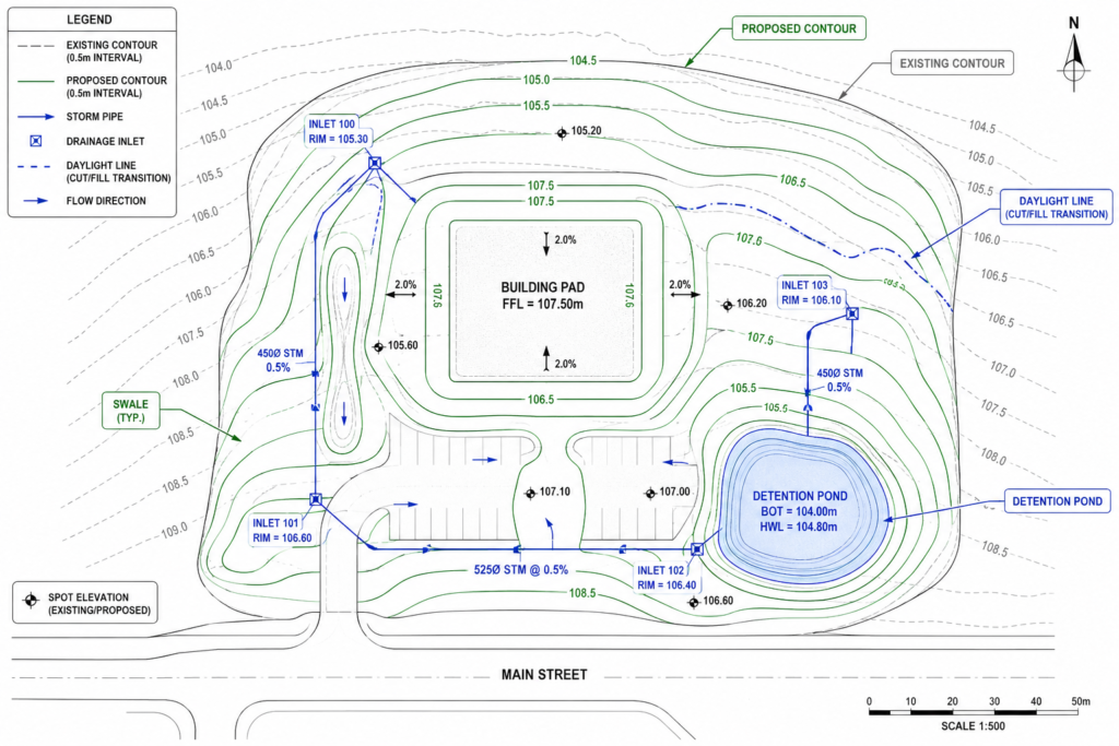
Drainage Design in Civil Engineering CAD: From Catchment to Outfall
Stormwater drainage design is the engineering discipline that prevents what was built on a site from flooding and from causing flooding to others downstream. Every impermeable surface created by development, every roof, road, and car park, increases the volume and rate of runoff from a site compared to the natural state. The drainage system is designed to manage that increase.
| Drainage Component | What It Does | Civil 3D / CAD Workflow |
| Catchment area | The land area that contributes runoff to a single point | Defined from surface analysis using watershed delineation tools |
| Time of concentration | The time for runoff to travel from the furthest point to the outlet | Calculated from slope and flow path length; FAA or Kirpich methods |
| Rational method (Q=CiA) | Calculates peak flow from rainfall intensity, area, runoff coefficient | Embedded in drainage design tools; catchment properties drive inputs |
| Inlet | Structure that collects surface runoff from roads or paving | Placed at low points and sumps; capacity calculated against flow |
| Pipe network | Buried pipes conveying collected runoff to outfall or storage | Designed in plan and profile; gradient and velocity checked in software |
| Detention pond | Basin that stores runoff and releases at a controlled rate | Sized by routing the design storm; stage-storage relationships defined |
| Underground storage | Subsurface crates or tanks replacing above-ground ponds | Civil 3D 2026+ models as native objects with inflow/outflow connections |
| HGL/EGL | Hydraulic and Energy Grade Lines showing pipe pressure state | Displayed in profile view in Civil 3D; confirms pipes not under pressure |
| Outfall | Where the drainage system discharges to a watercourse or sewer | Designed to prevent erosion; energy dissipation often required |
| Swale | Open channel with vegetated or lined base for surface drainage | Graded using TIN surface tools; sized for design flow without overtopping |
The Rational Method: How Peak Flows Are Calculated
The rational method is the most widely used approach to calculate peak stormwater flows from small catchments. The formula is Q = CiA, where Q is the peak flow in cubic metres per second, C is the dimensionless runoff coefficient representing how much of the rainfall becomes runoff (0.9 for impermeable paving, 0.2 for well-drained grass), i is the rainfall intensity in mm per hour for the design storm, and A is the catchment area in hectares.
The design storm is defined by its return period: a 1 in 10 year storm, a 1 in 100 year storm, or whatever the local stormwater authority requires for the development type. Rainfall intensity data comes from intensity-duration-frequency (IDF) curves specific to the project location. Civil 3D’s Rainfall Manager in the 2026 release allows these IDF data sets to be imported and managed as project libraries, eliminating the manual data entry that previously introduced errors into drainage calculations.
The time of concentration is the time it takes runoff to travel from the furthest point of the catchment to the outlet. It drives the rainfall intensity used in the rational method: longer concentration times correspond to lower intensities for the same return period. Civil 3D calculates flow path lengths and slopes from the surface model, providing the inputs to concentration time calculations automatically from the graded surface geometry.
Hydraulic Grade Line and Energy Grade Line in Pipe Network Design
The Hydraulic Grade Line (HGL) and Energy Grade Line (EGL) are the most important hydraulic outputs from a pipe network analysis. The HGL shows the water pressure level at each point in the pipe network. If the HGL rises above the pipe soffit (the top of the inside of the pipe), the pipe is operating under pressure and may surcharge, potentially causing flooding at inlets and access chambers.
Civil 3D 2026 displays HGL and EGL directly in the profile view after running a drainage analysis through the InfoDrainage-powered engine. This means engineers can see, within the same drawing view where they set pipe gradients and invert levels, whether the hydraulic performance of the system is acceptable for the design storm. Previously this required exporting to a separate hydraulic model and manually comparing results against the pipe profile drawing.
Detention and Water Sensitive Design
On most development sites above a minimum area, stormwater authorities require that post-development runoff rates do not exceed pre-development rates. This is achieved through detention: temporarily storing stormwater on site and releasing it slowly through a controlled outlet.
In Civil 3D 2026 and 2027, detention ponds and underground storage systems are modelled as native design objects with defined stage-storage relationships and outlet structures. The integrated analysis engine routes the design storm through the detention system and checks that the controlled release rate meets the authority’s pre-development flow target. Underground storage using modular crate systems is growing as a preference on urban sites where surface area is constrained, and Civil 3D’s expanded underground storage objects in 2026 reflect this shift.
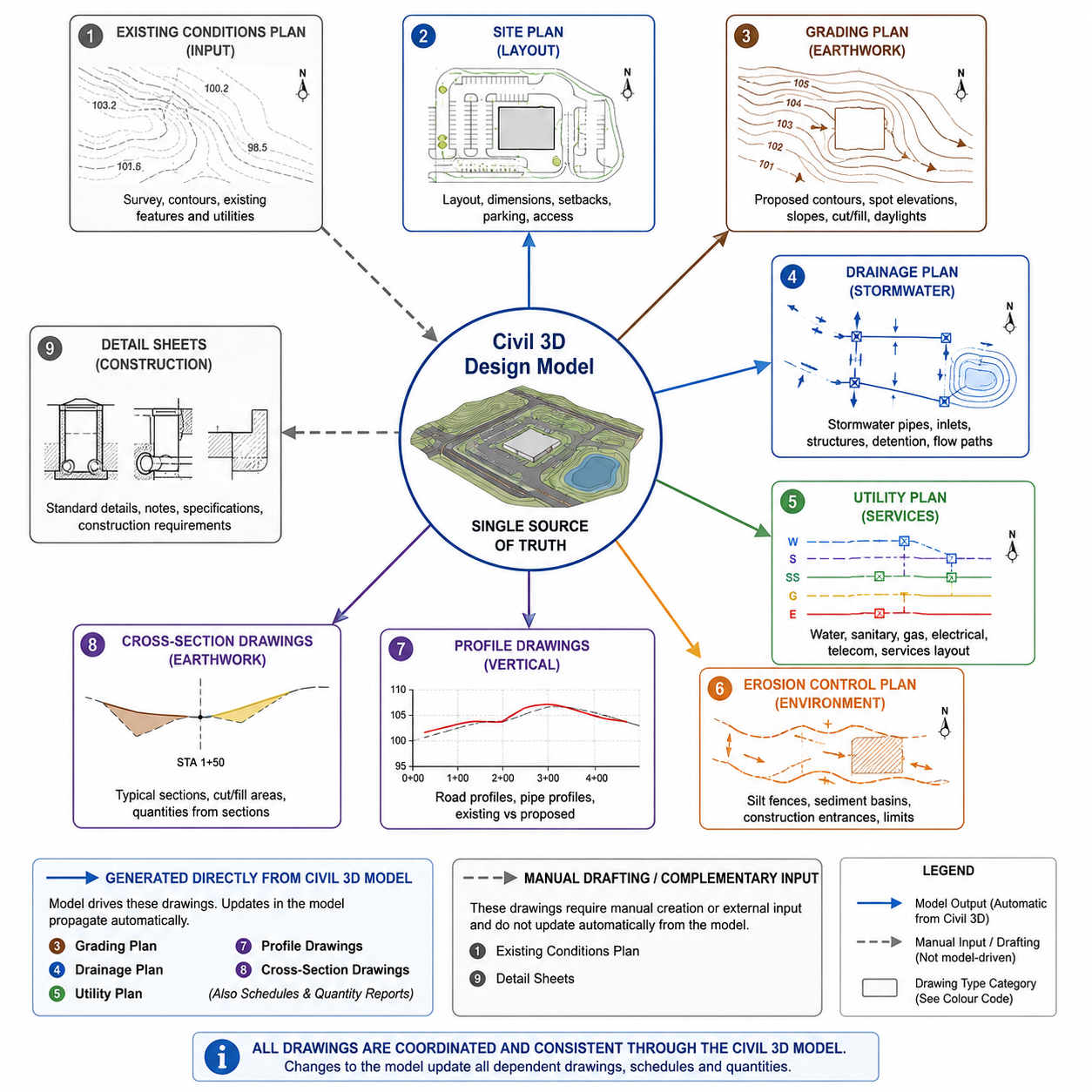
Civil Engineering Drawing Types: What Each Drawing Communicates
A civil drawing package for a land development project contains multiple drawing types. Understanding what each one communicates and who uses it prevents the common problem of contractors or permit authorities being given the wrong drawing for the wrong purpose.
| Drawing Type | What It Shows | Who Uses It |
| Existing conditions plan | Current topography, utilities, structures, easements, boundaries | Engineer, planner, permitting authority |
| Site plan | Proposed layout: buildings, roads, parking, utilities, landscaping | Architect, contractor, planning department |
| Grading plan | Proposed contours, spot elevations, cut and fill zones, slopes | Civil engineer, earthwork contractor, inspector |
| Drainage plan | Stormwater network: pipes, inlets, channels, detention, outfall | Civil engineer, stormwater authority, contractor |
| Utility plan | Water, sewer, gas, electrical routes and connection points | Utility engineer, contractor, local authority |
| Erosion control plan | Sediment barriers, check dams, hydroseeding, stabilisation zones | Inspector, contractor, environmental regulator |
| Horizontal control plan | Survey control points, bearings, distances, boundary data | Surveyor, contractor for layout |
| Profile drawing | Vertical view along a road or pipe alignment showing grades | Civil engineer, contractor, inspector |
| Cross-section drawing | Cut through terrain at stations showing existing and proposed | Earthwork estimator, contractor |
| Detail sheets | Standard details for kerbs, inlets, headwalls, pavement sections | Contractor, inspector |
The Importance of the Grading Plan as a Construction Document
The grading plan is the earthwork contractor’s primary reference during site preparation. It defines, in absolute terms, every finished level across the site. Contour intervals of 0.25m or 0.5m are standard on most grading plans. Spot elevations at building corners, drainage high points, road centrelines, and inlet covers provide the dimensional control points for setting-out the earthwork.
A grading plan that is ambiguous, internally inconsistent (where contours do not close at site boundaries), or missing spot elevations at critical control points forces the contractor to make assumptions. Those assumptions are rarely conservative. The resulting finished levels may not drain correctly, may conflict with adjacent finished levels, or may require costly regrading after initial construction.
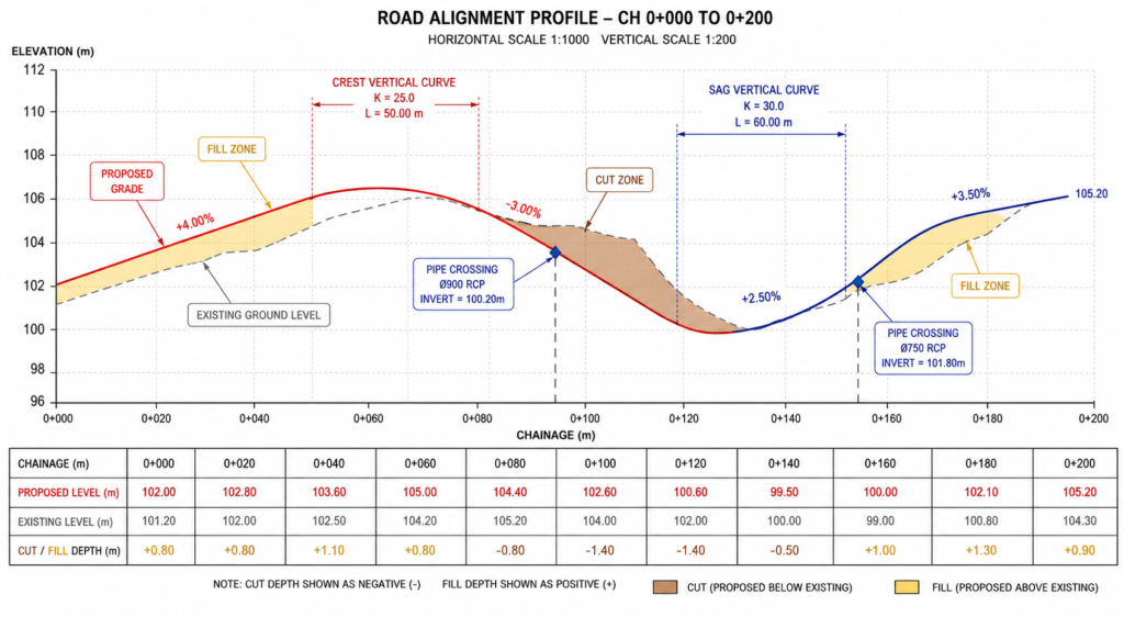
Profile Drawings: The Vertical Story
Every road alignment and every significant pipe run in a civil project has an associated profile drawing. The profile shows the vertical alignment, the relationship between existing ground level and proposed level along the centreline, the location of vertical curves, and the gradient of each tangent section.
For drainage pipe networks, the profile view is where pipe gradients are set and where the hydraulic grade line is checked. Conflicts between pipes and other buried services, between pipe obvert levels and road subgrade, and between pipe invert levels and downstream connection points are all identified and resolved in the profile drawing. A pipe network that looks acceptable in plan view frequently reveals conflicts in profile that must be resolved before construction.

Civil Engineering CAD Software in 2026: Honest Comparison
The civil engineering CAD software landscape in 2026 is dominated by the Autodesk Civil 3D ecosystem in North America and Australia, and the Bentley suite in UK DOT and infrastructure contexts. Understanding the role of each tool prevents the common mistake of using the wrong tool for a stage of work it was not designed for.
| Software | Developer | Primary Civil Use | Key Strength | 2026 Status |
| Civil 3D | Autodesk | Site, roads, drainage, corridors | Dynamic model, US standard | Civil 3D 2027 released April 2026 |
| AutoCAD | Autodesk | 2D drafting, details, annotations | Universal DWG standard | Still essential alongside Civil 3D |
| Bentley OpenRoads | Bentley | Roads, rail, DOT projects | ISO/DOT integration, MX data | Strong in DOT/rail sectors |
| MicroStation | Bentley | Infrastructure design, 3D modelling | DOT legacy, international | Common in UK, Australia, transport |
| InfraWorks | Autodesk | Conceptual and planning studies | GIS integration, 3D context | Cloud-connected, early-stage design |
| InfoDrainage | Autodesk | Stormwater design and analysis | Full hydrological modelling | Integrated in Civil 3D 2026+ |
| QGIS | Open source | GIS analysis, catchment mapping | Free, GIS-native, open format | Widely used for spatial analysis |
| EPASWMM | US EPA | Stormwater network simulation | Free, hydraulic routing | Benchmark for drainage analysis |
| Revit (civil) | Autodesk | Infrastructure BIM, MEP coordination | BIM Level 2+ coordination | Growing use for civil-structural |
Civil 3D vs AutoCAD: They Are Not the Same Tool
This distinction matters and is frequently misunderstood outside the profession. AutoCAD is a general-purpose drafting platform. Civil 3D is AutoCAD with a complete set of civil engineering-specific objects and workflows built on top of it. You can produce a civil site plan in AutoCAD using 2D lines and manual text. The moment you need grading surfaces, dynamic pipe networks, corridor models, or volume calculations, AutoCAD cannot do it without Civil 3D.
In practice, most civil engineers use both. Civil 3D for all design work where the civil model drives the output. AutoCAD for standard detail sheets, as-built documentation, and markup work where the civil objects are not needed. The two environments are fully compatible because Civil 3D is AutoCAD, with a significant additional layer of civil engineering capability.
What Civil 3D 2027 Adds to the Civil Workflow
Civil 3D 2027, released in April 2026, introduces the Autodesk Assistant, which brings an AI-powered conversational interface into the Civil 3D design environment. Engineers can ask the Autodesk Assistant questions about Civil 3D workflows, get guidance on specific commands, and access a curated prompt library and searchable chat history for project documentation.
The 2027 release also introduces a tech preview for automated daylight line generation, where the software generates the daylight line (the boundary between cut or fill slope and existing ground) automatically from grading criteria without the engineer having to manually construct complex grading objects. This automates one of the most time-consuming and error-prone steps in conventional grading design.
The drainage analysis capabilities continue to expand: FAA and Kirpich time of concentration methods are added, arch and elliptical pipe types are supported in analysis, and pond porosity can now be defined for underground storage systems. These are not cosmetic updates. They address real limitations in previous releases that caused engineers to maintain separate analysis tools for these scenarios.
Erosion Control and Sediment Management: The Drawing That Gets Projects Permitted
No grading plan gets approved without an accompanying erosion and sediment control plan (ESCP) in most jurisdictions. This requirement reflects the environmental reality that disturbed soil erodes rapidly under rainfall, generating sediment that enters waterways and causes significant ecological and flood risk impacts.
The ESCP shows the temporary measures installed during construction to prevent sediment leaving the site: silt fences at the site boundary, straw wattles at drainage lines, sediment basins capturing runoff from active earthwork areas, stabilised construction access points preventing mud tracking onto public roads, and staged revegetation or surface stabilisation as works progress.
In CAD terms, the ESCP is often one of the more labour-intensive drawings to produce because its content changes as the construction sequence progresses. Civil 3D’s dynamic model helps because the terrain information needed to position sediment basins and flow paths is already in the model. But the detail of the control measures themselves is typically drafted using standard civil detail symbols and requires the engineer’s judgment about construction phasing and likely flow patterns during each phase.
Civil BIM: How Civil Engineering CAD Is Connecting to the Wider Project Model
Civil engineering has been slower than building services and structural engineering to adopt full BIM workflows, partly because the relevant objects in civil design, terrain surfaces, alignments, pipe networks, have not historically been as well-integrated into the BIM coordination platforms used for building projects.
Civil 3D 2026 and 2027 address this through closer integration with Autodesk Construction Cloud. Civil models can be shared in real time to ACC for coordination with architectural and structural models. Civil Tools in the ACC Model Coordination Viewer allow structural and MEP teams to see civil alignments and pipe networks alongside their own models, identifying service crossing conflicts before construction without requiring the civil engineer to attend every coordination meeting.
The practical impact is most significant on projects where civil infrastructure, basement structures, and building foundations interact closely. A drainage pipe that must cross under a deep raft foundation, or a service that must pass through a retaining wall, used to be coordinated by the engineers trading DWG files and checking manually. In a shared ACC environment, the coordination is visible to all parties in real time.
10 Civil CAD Mistakes That Send Projects Back to the Drawing Board
The civil CAD errors that cost the most time and money on projects are predictable. Most of them reflect a disconnect between what the drawing shows and what the physical site, the local authority requirements, or the laws of hydraulics actually demand.
| Mistake | What Goes Wrong | How to Prevent It |
| Grading without checking flood plain data | Building pad set below 100-year flood level | Check FEMA FIRM maps and local flood study data before setting finished floor levels. |
| Slope too flat on paved surfaces | Ponding on roads and car parks | Minimum 0.5% slope on all paved surfaces; 1% preferred on car parks to account for construction tolerance. |
| No freeboard allowance on detention | Pond overflows in larger-than-design event | Provide minimum 300mm freeboard above the design water surface level in detention structures. |
| Pipe gradient too flat | Sediment builds up, blockage, flooding | Minimum 0.5% gradient for stormwater pipes; 1% for gravity sewer. Check self-cleansing velocity. |
| Cut and fill not balanced on site | Large export or import of material = extra cost | Use Civil 3D volume dashboard to check cut/fill balance before finalising grading. Aim for earthworks neutrality. |
| Drainage outfall unprotected | Scour and erosion at pipe exit | All outfalls need energy dissipation: riprap apron, concrete headwall, or energy basin. |
| Daylight lines inside property boundary | Cut or fill slope extends onto neighbouring land | Check daylight line positions against cadastral boundaries early. Adjust slopes or add retaining walls. |
| Contours not closing at boundary | Drawing errors confuse contractor, poor grading | All proposed contours must terminate at existing contours or at site boundary correctly. |
| Ignoring utility conflicts in grading | Grading covers utility access lids or reduces cover | Overlay utility plans before finalising grading. Minimum cover to buried services varies by asset type. |
| No erosion control plan with grading | Permit refusal or site shutdown from regulator | Always accompany a grading plan with a construction phase erosion and sediment control plan. |
| The mistake that carries the highest single-project cost: Setting finished floor levels and building platform elevations without checking FEMA FIRM maps (US), local flood study data (Australia and UK), or the relevant national flood authority mapping. A building platform set below the 1 in 100 year flood level will fail the permit check, requiring redesign of the entire grading model. On tight urban sites, there may be no solution without raising the entire development and renegotiating road access profiles. Always check flood data before committing to any finished floor elevation. |
AI in Civil Engineering CAD: What Is Actually Changing in 2026
Artificial intelligence is arriving in civil engineering CAD through the same channels it is arriving everywhere else: embedded in software tools rather than as a separate AI overlay on top of existing workflows. The practical changes happening now are worth understanding separately from the longer-term potential.
AI-Assisted Grading in Civil 3D 2027
The automated daylight line generation preview in Civil 3D 2027 is the most direct AI-adjacent feature in the current release cycle. Daylight lines, the boundaries between cut or fill slopes and the existing ground surface, have historically required the engineer to manually construct grading objects that can be complex and fragile when the design changes. The new tech preview generates these lines automatically from grading criteria, reducing one of the most time-consuming manual steps in surface grading design.
The Autodesk Assistant in Civil 3D 2027 provides conversational access to Civil 3D knowledge within the design environment. Engineers can ask workflow questions, retrieve command guidance, and access documentation without leaving the software. For less experienced Civil 3D users, this reduces the time spent switching between the software and online help resources, which on complex grading workflows can represent a meaningful efficiency gain.
AI for Drainage Analysis and Design Optimisation
The Dynamo automation platform in Civil 3D 2026.2 added over 75 new nodes specifically for stormwater control objects, with AI-powered node autocomplete to help engineers build automation scripts for drainage configuration without writing code manually. This brings parametric automation to pond sizing, underground storage configuration, and drainage network setup in a way that previously required scripting expertise.
Cloud-based drainage analysis through InfoDrainage integration allows engineers to run multiple storm scenarios rapidly and compare results within the Civil 3D environment. The speed of cloud computation means what was previously a half-day process of iterating drainage system design, running the analysis, reviewing results, and making changes is compressed into a workflow where iteration cycles take minutes rather than hours.
Using AI for Civil Engineering Documentation
Beyond the CAD environment itself, AI tools including Claude are being used in civil engineering practices to accelerate the documentation layer of projects. Civil engineering reports, stormwater management plans, drainage calculations reports, and permit application supporting documentation all require significant structured writing that draws on the numerical outputs from the CAD model.
Structured outputs from Civil 3D, pipe schedules, volume reports, catchment area tables, can be processed by AI tools to generate formatted stormwater management reports, earthwork summaries, and permit application supporting documentation in a fraction of the time required for manual preparation. The engineering content, the calculations and the technical decisions, remains the engineer’s responsibility. The communication layer, presenting those decisions clearly in a regulatory submission, is where AI tools reduce time without compromising the technical integrity of the deliverable.
Conclusion:
The shift from 2D drafting to dynamic civil engineering modeling in Civil 3D represents something more fundamental than a software upgrade. A 2D site plan drawn in AutoCAD is a static record of decisions already made. A Civil 3D model is a live, interconnected representation of engineering decisions where changing any element causes the affected elements to update.
That interconnectedness is what makes civil engineering CAD in 2026 so different from the discipline of even ten years ago. Change the road alignment and the grading changes. Change the grading and the drainage catchments change. Change the catchments and the pipe sizes change. Every design iteration is a full update of the entire civil model, not a manual chase through dozens of drawings to find and update every affected detail.
The civil engineers who understand the system, who know how to build a surface model from survey data, how to grade it for drainage, how to size a pipe network against a design storm, and how to produce a coordinated drawing package that can be permitted and built without ambiguity, are the ones delivering projects that go from design to construction without the expensive rework loops that define poorly coordinated civil design.
In 2026, that system is becoming more intelligent, with AI-assisted daylight lines, integrated cloud drainage analysis, and connected BIM environments linking civil models to building coordination. The fundamentals, accurate survey data, disciplined grading, properly sized drainage, and complete coordinated drawings, have not changed and will not change.
Get the terrain right. Grade it correctly. Drain it completely. Document it precisely.
Frequently Asked Questions
What CAD software do civil engineers use for site plans and grading?
Civil engineers most commonly use Autodesk Civil 3D for site plans, grading design, and drainage. It is built on AutoCAD and adds civil-specific tools: dynamic surface modeling, corridor design, grading objects, and pipe networks that all update when the design changes. AutoCAD is used alongside Civil 3D for 2D drafting, standard details, and as-built documentation. Bentley OpenRoads and MicroStation are the main alternatives, particularly on US Department of Transportation projects and UK infrastructure work. InfraWorks handles early-stage planning and GIS-connected feasibility studies.
What is a grading plan in civil engineering?
A grading plan is a civil engineering drawing that shows how existing ground levels will be changed across a development site. It uses proposed contour lines and spot elevations to show where material is cut (removed) and where fill is placed to create the finished levels for buildings, roads, car parks, and drainage features. The grading plan is the document that earthwork contractors follow during site preparation. It also shows the boundaries of cut and fill zones, slope gradients, daylight lines, and drainage directions across the finished surface.
What is the difference between a site plan and a grading plan?
A site plan shows the layout of a proposed development in plan view: where buildings, roads, car parks, and landscape areas are located. A grading plan shows how the ground surface will be reshaped to accommodate that layout, at what elevation each feature sits, and how stormwater drains away from buildings and paved areas. The site plan answers where things are. The grading plan answers how high they are and how water moves across them. Both are required for planning permission and building permits on most development projects.
How does Civil 3D work for drainage design in 2026?
Civil 3D 2026 and 2027 integrate stormwater drainage design directly into the civil model through InfoDrainage-powered analysis tools. Engineers design catchment areas, pipe networks, ponds, channels, and underground storage within the Civil 3D environment. Cloud-based analysis runs storm event simulations and returns Hydraulic Grade Line and Energy Grade Line results directly in the design profiles, without leaving the model. This allows engineers to validate drainage system performance and iterate the design in the same workflow where grading and site geometry is produced.
What are the key slope standards civil engineers use in site grading?
Standard slope requirements in site grading include: minimum 0.5 percent on paved roads and surfaces to prevent ponding (1 percent preferred on car parks), minimum 2 percent slope away from building platforms on landscaped areas, maximum 2H:1V (50 percent) for cut and fill slopes in soil without geotechnical assessment, and minimum 0.5 percent gradient on stormwater pipes. DDA and ADA pedestrian path requirements limit cross-falls to 2 percent and running grades to 5 percent without a formal ramp design.
What is cut and fill in civil engineering site grading?
Cut is where the proposed finished ground level is lower than the existing ground, meaning material is excavated and removed. Fill is where the proposed level is higher than existing ground, meaning material is imported and compacted. Civil 3D calculates cut and fill volumes by comparing the existing surface model against the proposed grading surface. Balancing cut and fill volumes across a site reduces material haulage costs significantly. Material excavated in cut zones is used as fill elsewhere on the site when it meets compaction specifications.
‘Autodesk Civil 3D 2026 official documentation and learning resources‘
Leave a Reply