Tag: cad

  • How Much Does CAD Drafting Cost? 2026 Pricing Guide

    How Much Does CAD Drafting Cost? 2026 Pricing Guide

    One of the most common questions engineering managers, architects, and small business owners ask when a new project lands on their desk is deceptively simple: what is this going to cost in drafting?

    The honest answer is that CAD drafting costs span a wide range, from under $50 for a basic conversion task to well over $50,000 for a complex commercial construction drawing package. The range is not arbitrary. It reflects real differences in drawing complexity, drafter experience, project discipline, delivery speed, and where in the world the work is being done.

    Most pricing articles on this topic give you a number and move on. This guide goes deeper. We break down costs by drawing type, discipline, pricing model, and provider category. We explain every factor that moves the price up or down. We include a practical budget-planning section and a red flag list for quotes that do not pass the smell test. By the end, you will know not just what CAD drafting costs, but why it costs what it does, and how to get better value from every dollar you spend.

    Quick Answer: CAD Drafting Cost at a Glance
    If you need a number right now, here is where most CAD drafting projects land based on current market data compiled from vendor pricing pages, industry surveys, and published rate data for 2026-2026:
    CAD drafting cost comparison chart showing price ranges for 2D drafting, 3D modeling, BIM services, and shop drawings in 2026
    Pricing MetricTypical RangeNotes
    Hourly rate (domestic freelancer)$45 – $95/hrVaries by discipline and experience
    Hourly rate (domestic firm)$75 – $150/hrIncludes overhead, QA, account management
    Hourly rate (offshore firm)$8 – $35/hrVaries significantly by region and quality tier
    Per-sheet rate (2D CAD conversion)$45 – $250/sheetRush turnaround doubles or triples cost
    Simple 2D drawing package$150 – $800Single-page layouts, basic floor plans
    Standard residential drawing set$800 – $3,500Full permit-ready plans for a home
    Commercial drafting package$5,000 – $30,000+Multi-discipline, multi-sheet sets
    3D CAD model (single component)$300 – $2,500Complexity and tolerance precision drive cost
    BIM model (full building)$8,000 – $50,000+Depends on LOD and number of disciplines
    Monthly retainer (outsourced)$1,200 – $6,000/moDedicated or shared resource block
     Important framing:  These ranges reflect real market data, not optimistic estimates. The bottom of each range represents straightforward work from lower-cost providers. The top reflects complex, high-stakes deliverables from experienced domestic firms. Most real projects land somewhere in the middle.

    2. What Determines CAD Drafting Pricing? The 7 Core Variables

    CAD drafting is not a commodity where one price fits all. Every quote you receive reflects a specific combination of the following factors. Understanding each one helps you assess whether a quote is fair, and gives you tools to control your costs.

    Infographic showing seven variables that determine CAD drafting cost complexity, drafter experience, software, turnaround time, provider location, revisions, and project volume

    Variable 1: Drawing Complexity

    Complexity is the single biggest cost driver in CAD drafting. A simple 2D floor plan redraw with clean linework and basic dimensions might take a skilled drafter three to five hours. The same space drawn with structural details, MEP coordination, material specifications, and permit-ready annotation can take fifteen to thirty hours. That difference directly multiplies your cost.

    Complexity factors include the number of distinct components or rooms, the level of annotation and dimensioning required, whether the drawing needs to meet code compliance or permit submission standards, how many layers and disciplines must be coordinated, and whether 3D modeling or BIM data is involved alongside 2D output.

    Variable 2: Drafter Experience and Specialization

    An entry-level drafter working in AutoCAD LT will produce basic 2D layouts accurately and affordably. A senior mechanical engineer who also drafts will charge three to four times more per hour, but may deliver a complete SolidWorks assembly package with GD&T annotations, BOM, and manufacturing notes in a fraction of the time. Specialization commands a premium. Structural steel detailing, medical device drafting, aerospace documentation, and MEP coordination drawings all require expertise that general drafters do not have, and the market rates for specialists reflect that.

    Variable 3: Software and Deliverable Format

    The software platform matters both for capability and cost. An AutoCAD 2D drawing is the most common and typically the least expensive output. SolidWorks or CATIA 3D models involve more complex workflows and higher-cost software licenses, which factor into quoted rates. Revit BIM deliverables require BIM-trained professionals and carry a premium over standard CAD. If you require deliverables in a specific format (native DWG, STEP, IFC, PDF, DXF), or need files structured to a specific standard like ISO or AIA layering, mention this upfront, as non-standard requirements affect time and cost.

    Variable 4: Turnaround Time

    Rush work costs more, often significantly more. Most CAD drafting providers have tiered pricing based on delivery speed. Standard turnaround (5 to 10 business days) is typically the baseline rate. Three-day delivery often carries a 25 to 50 percent premium. Same-day or next-day delivery, when available, can double the base price. If your timeline is flexible, communicate that clearly. Some providers discount work with relaxed deadlines, using it to fill gaps between priority projects.

    Variable 5: Provider Location

    Where the drafting is done dramatically affects what you pay. A domestic US firm in a major metropolitan area will charge two to five times what an equivalent-quality offshore firm in India or the Philippines charges for the same drawing. The cost difference is real, but so are the tradeoffs in communication, time zone overlap, and IP handling. The pricing section on domestic versus offshore providers covers this in detail.

    Variable 6: Number of Revisions

    Revisions are a significant and often underestimated cost driver. Most drawing packages include a defined number of revision rounds in the base quote (commonly one or two rounds of minor changes). Changes beyond that scope are billed at the hourly rate, which can substantially increase total project cost. Poor upfront briefing is the main cause of excessive revision cycles. The clearer and more complete your design intent and specifications are at the start, the fewer revision rounds you will need.

    Variable 7: Project Scale and Volume

    Volume pricing is real. A single drawing sheet costs proportionally more than a batch of fifty similar sheets. If you have an ongoing, high-volume drafting need, most firms will offer a reduced per-sheet or per-hour rate in exchange for a committed volume or retainer arrangement. Conversely, minimum project charges (typically $150 to $250 for most firms) mean that very small one-off requests are often not worth outsourcing individually.

    3. CAD Drafting Hourly Rates: A Realistic Breakdown

    Hourly billing is the most transparent and flexible pricing model for CAD drafting, and it is the dominant model for iterative or undefined-scope work. Here is what the market looks like in 2026-2026 across provider types and experience levels.

    Bar chart comparing CAD drafting hourly rates by provider type from entry-level freelancers to domestic firms in 2026
    Provider TypeEntry LevelMid LevelSenior / SpecialistNotes
    US Domestic Freelancer$30 – $45/hr$45 – $75/hr$75 – $120/hrRates vary by discipline; structural and MEP specialists at the top
    US Domestic Firm$60 – $80/hr$80 – $120/hr$100 – $175/hrIncludes project management, QA, software overhead
    UK / Western Europe Firm£45 – £65/hr£65 – £100/hr£95 – £150/hrComparable to US in GBP; EU regulations familiarity a plus
    Eastern Europe (Poland, Romania)$20 – $35/hr$35 – $55/hr$50 – $80/hrStrong technical quality; growing for BIM and complex drafting
    India-Based Firm$8 – $15/hr$15 – $25/hr$22 – $40/hrLargest offshore talent pool; quality varies significantly
    Philippines-Based Firm$10 – $18/hr$18 – $30/hr$25 – $45/hrStrong English proficiency; good AEC and MEP drafting capability

    What Is Included in an Hourly Rate?

    When you hire a domestic firm at $100 per hour, you are not just paying for the drafter’s hands on a mouse. That rate typically covers:

    • The drafter’s time and expertise
    • Software license costs (AutoCAD at $1,975/year, Revit at $2,310/year, SolidWorks at $4,000+ per year)
    • Internal quality review before delivery
    • File management and delivery infrastructure
    • Project management and communication overhead
    • The firm’s business overhead including insurance, office, and administrative staff

    When you hire a solo freelancer at $55 per hour, most of those costs are lower or absent, which explains the rate difference. Neither is inherently better — the right choice depends on your project’s complexity and what level of process and oversight you need.

    4. Per-Sheet and Per-Project Pricing: When Each Makes Sense

    Per-Sheet Pricing

    Per-sheet pricing is common for CAD conversion work, PDF-to-DWG conversion, permit drawing sets, and other tasks where each sheet is a discrete, standardized deliverable. It is popular with clients because it is predictable: you know how many sheets you need, you multiply by the rate, and you have your budget.

    Drawing Sheet TypeTypical Per-Sheet RateRush MultiplierNotes
    PDF to CAD conversion (basic)$45 – $90/sheet2 – 3xSimple linework, minimal annotation
    PDF to CAD conversion (detailed)$90 – $180/sheet2 – 4xFull annotation, dimensions, notation
    Architectural floor plan (new draw)$150 – $350/sheet1.5 – 2xOriginal drafting from sketches or notes
    Structural detail sheet$200 – $450/sheet1.5 – 2.5xIncludes member sizing, connection details
    MEP (mechanical/electrical/plumbing)$175 – $400/sheet1.5 – 3xCoordination complexity adds cost
    Shop drawing (fabrication)$150 – $350/sheet1.5 – 2xWeld symbols, tolerances, BOM
    Civil site plan$250 – $600/sheet1.5 – 2xSurvey data integration, grading, utilities
    On rush pricing:  One published provider (CAD/CAM Services) lists a flat rate of $185 per D or E size AutoCAD 2D sheet at standard turnaround. The same work at rush turnaround (24 hours) typically runs $370 to $550. Plan your deadlines accordingly.

    Per-Project (Fixed Fee) Pricing

    Fixed-fee pricing works well when the scope is clearly defined and the deliverables are well-understood. The drafter agrees to produce a specific set of outputs for a set price. You get budget certainty; the drafter accepts the risk if the job takes longer than estimated.

    Fixed-fee pricing is common for residential drawing packages, permit submission sets, and defined industrial or manufacturing drawing packages. It is less common for complex commercial or industrial projects where scope evolves during the engagement.

    Project TypeTypical Fixed-Fee RangeWhat Is Usually Included
    Simple 2D drawing (single sheet)$150 – $400Line conversion or basic redraw, one revision round
    Small residential renovation drawings$800 – $2,700Floor plans, elevations, basic sections for permit
    Full custom home drawing set$3,500 – $10,000+Full architectural set: plans, sections, elevations, details
    Small commercial building (permit set)$5,000 – $15,000Multi-discipline permit package, ADA compliance
    Medium commercial / industrial$15,000 – $35,000Full structural, MEP, architectural coordination
    Large commercial or industrial project$35,000 – $100,000+Multiple disciplines, extensive coordination, BIM deliverables
    Product design (simple mechanical part)$300 – $1,5003D model, 2D drawing package, BOM
    Product design (complex assembly)$2,000 – $15,000+Multi-component assembly, GD&T, manufacturing drawings

    5. Cost by Drawing Type and Discipline

    CAD drafting costs vary significantly across disciplines. The differences are not arbitrary: they reflect the level of specialized knowledge required, the complexity of applicable standards and codes, and the typical time investment per drawing.

    Architectural CAD Drafting Costs

    Architectural drafting is one of the most common CAD services and covers a wide range of work from basic floor plans to complex construction document sets. Costs are driven by the number of sheets, the level of detail, and whether permit submission formatting is required.

    • Basic floor plan (single level): $300 – $800
    • Full residential permit set (plans, elevations, sections, details): $1,500 – $5,000
    • Commercial permit-ready drawing package: $8,000 – $30,000+
    • As-built drawings (measured and drawn): $500 – $3,000 depending on size and complexity
    • PDF to AutoCAD conversion (per sheet): $45 – $180

    Architectural drafting rates for domestic freelancers average $75 to $125 per hour. This is substantially less than hiring a licensed architect, whose hourly rates run $200 to $400 per hour. For pure drafting work (translating a design into accurate CAD output), a skilled architectural drafter is the appropriate choice, not an architect.

    Mechanical Engineering CAD Drafting Costs

    Mechanical CAD drafting is where precision is paramount. Drawings must convey exact dimensions, tolerances, material specifications, and surface finish requirements in a format that machinists and fabricators can execute without ambiguity. This level of precision requires experienced drafters and commands higher rates than basic architectural work.

    • Simple machined part (2D drawing): $150 – $600
    • Complex machined part with GD&T: $400 – $1,500
    • 3D solid model (single component): $300 – $2,000
    • Sub-assembly drawing package: $800 – $4,000
    • Full product assembly with BOM and exploded views: $2,000 – $15,000+

    Mechanical CAD specialists in AutoCAD Mechanical, SolidWorks, or CATIA typically bill $65 to $120 per hour domestically. The premium over general drafting rates reflects the knowledge of manufacturing processes, GD&T standards (ASME Y14.5), and the criticality of getting tolerances right.

    Structural Engineering CAD Drafting Costs

    Structural drafting covers foundation plans, framing plans, structural steel details, rebar layouts, and connection details. It sits at the intersection of engineering judgment and drafting skill, meaning the best structural drafters have a solid understanding of structural behavior, not just drafting technique.

    • Foundation plan: $400 – $1,200
    • Structural steel shop drawings (per sheet): $200 – $450
    • Rebar detailing drawings (per sheet): $150 – $350
    • Full structural drawing package for a residential project: $1,500 – $4,000
    • Commercial structural documentation package: $8,000 – $40,000+

    Structural shop drawings are a category where outsourcing to specialized overseas firms is extremely common. Firms in India and the Philippines have built strong capabilities specifically in steel detailing and rebar drawings for US and UK markets, typically charging $15 to $30 per hour for what domestic firms bill at $90 to $150 per hour.

    Civil Engineering CAD Drafting Costs

    Civil CAD drafting covers site plans, grading plans, utility layouts, road designs, and land development drawings. Civil work often involves integration with survey data, GIS systems, and regulatory formatting requirements that vary by municipality.

    • Basic site plan: $500 – $1,500
    • Full land development drawing package: $3,000 – $15,000
    • Road design drawings (per sheet): $300 – $700
    • Utility layout drawings (per sheet): $200 – $500
    • Civil 3D model (grading and drainage): $1,500 – $8,000

    MEP (Mechanical, Electrical, Plumbing) Drafting Costs

    MEP drafting is among the most complex and expensive CAD work because it requires coordination between three distinct systems, all of which must occupy the same physical building space without conflict. MEP drawings are increasingly produced in BIM to enable clash detection.

    • HVAC layout drawing (per floor): $600 – $2,000
    • Electrical layout drawing (per floor): $400 – $1,500
    • Plumbing riser diagram: $300 – $900
    • Full MEP coordination package for a commercial building: $15,000 – $60,000+
    • BIM model with MEP coordination and clash detection: $20,000 – $80,000+

    BIM Modeling Costs

    Building Information Modeling (BIM) represents the highest tier of CAD-related drafting cost. BIM is not just drawing: it is a data-rich 3D model that carries information about every component in a building, including material properties, manufacturer data, maintenance requirements, and spatial relationships. The Level of Development (LOD) spec required significantly determines cost.

    BIM Level of DevelopmentWhat It IncludesTypical Cost Impact
    LOD 100 (Conceptual)Massing and overall form onlyLowest cost; schematic only
    LOD 200 (Approximate Geometry)Generic elements, approximate sizesModerate cost; early design phase
    LOD 300 (Specific Geometry)Accurate dimensions, coordination-readyStandard for permit/construction use
    LOD 350 (Construction)Interfaces with adjacent elements includedHigh cost; needed for fabrication coordination
    LOD 400 (Fabrication)Full fabrication and installation detailVery high cost; used for prefab and shop drawing production
    LOD 500 (As-Built)Verified field conditions, actual installed stateHighest cost; full as-built documentation

    6. Domestic vs Offshore CAD Drafting: The Real Cost Comparison

    The cost gap between domestic and offshore CAD drafting is large, and it is worth examining honestly rather than in generalities.

    Cost FactorDomestic (US/UK)Offshore (India/Philippines)Notes
    Hourly rate$65 – $150/hr$8 – $30/hr4 – 10x difference in base rate
    Time zone overlapFull overlapMinimal (8 – 12 hrs difference)Offshore requires asynchronous workflow
    Communication frictionLowModerate to HighDepends on provider’s English proficiency and process maturity
    Revision cycle timeHours1 – 2 daysTime zone gap extends correction loops
    IP risk levelLowModerateManageable with proper contracts; not eliminated
    Drawing quality ceilingVery highHigh for standardized work, variable for complexBest offshore firms deliver excellent output
    Total effective cost (with mgmt overhead)$75 – $160/hr est.$20 – $55/hr est.Offshore savings real but not as large as rate gap suggests

     The real saving:  If a domestic firm charges $100/hr and an offshore firm charges $18/hr, your raw cost savings are 82%. But management overhead, revision cycles, and QA review typically consume 30 to 50% of those savings. Real net savings for well-managed offshore arrangements typically run 40 to 60% compared to equivalent domestic work. Still significant, but calibrate expectations honestly.

    7. Freelancer vs Firm vs Outsourcing Agency: Pricing Differences

    Beyond geography, the type of provider you hire shapes both cost and experience significantly.

    Provider ModelHourly Range (Domestic)Best ForRisk Factors
    Solo freelancer$30 – $95/hrWell-defined projects, cost-conscious budgetsSingle point of failure; limited capacity; inconsistent availability
    Small specialist firm (2-10 people)$65 – $130/hrMid-complexity projects needing some team depthLimited surge capacity; still owner-dependent
    Established CAD firm$85 – $175/hrComplex, multi-sheet, regulated-industry workHighest cost; best process and accountability
    Offshore outsourcing firm$8 – $35/hrVolume drafting, standardized work, cost reductionCommunication overhead; QA management required
    Freelance platform (Upwork, Freelancer)$15 – $80/hrQuick tasks, price testing, low-stakes projectsHighly variable quality; no accountability structure
    Retainer / dedicated resourceNegotiated monthly rateOngoing high-volume needsRequires volume commitment; not flexible for sporadic work

    8. The Hidden Costs No One Talks About

    The quoted price for a CAD drafting project is often not the final price. These additional costs catch clients off guard repeatedly, and they deserve direct attention.

    Revision Costs Beyond Scope

    Most quotes include one or two rounds of minor revisions. Changes beyond that, whether driven by a design change on your end or a misunderstanding in the brief, are billed at the hourly rate. On a complex drawing package, multiple out-of-scope revision cycles can easily add 20 to 40 percent to the original quote. The solution is a comprehensive brief at the start, not a fight with your provider at the end.

    Format Conversion and File Compatibility

    If your provider works in one software platform and you need files in another, expect conversion fees. DWG to DXF is simple. AutoCAD to CATIA native format is not. File format requirements should be specified clearly in the brief and confirmed as included in the quote. Discovering at delivery that your machine shop needs a STEP file when you were expecting DWG files is a costly surprise.

    Minimum Project Fees

    Most professional CAD drafting providers have minimum fees, typically between $150 and $250. A five-minute correction that takes 30 minutes of a drafter’s time, including file handling and delivery, may still cost you the minimum. For very small, frequent requests, a retainer arrangement or in-house capability is usually more economical than individual project billing.

    Rush Premiums

    Rush fees are real and significant. A drawing that costs $500 at standard turnaround may cost $800 to $1,200 at two-day delivery. For same-day or next-day delivery (when available), premiums of 100 percent or more are not unusual. If you find yourself frequently paying rush rates, the root problem is usually project planning and timeline management, not drafting capacity.

    Back-and-Forth Communication Time

    This cost is invisible but real. Every email thread chasing clarification, every video call to explain a markup, every iteration of a brief that was not clear the first time represents time you are paying for indirectly (in management overhead) or paying for directly (in revision billing). Investing 30 to 60 minutes in a thorough project brief almost always saves more time and money than it costs.

    Software License Fees (When Applicable)

    Some specialized deliverables require proprietary software licenses. If you need a Revit model and your preferred firm works in AutoCAD, either the firm will need to bring in a Revit resource (which costs more) or you will need to engage a different firm. Similarly, if you require CATIA or Creo deliverables, expect a reduced pool of providers and higher rates. Always specify required software in your brief.

     Cost trap:  The single most expensive mistake in CAD drafting procurement is providing an incomplete brief and assuming the drafter will figure out the rest. Ambiguity in scope almost always resolves at your expense.

    9. How to Budget for a CAD Drafting Project

    Accurate budget planning for CAD drafting requires more than looking up a price range. Here is a practical process that experienced project managers use.

    Step 1: Define Your Deliverables Before You Ask for a Quote

    Write down exactly what you need: how many drawing sheets, what views (plan, section, elevation, detail, isometric, 3D model), what software format, what layering standard, what annotation level, and what the final use will be (permit submission, fabrication, client presentation, internal reference). The more specific your scope, the more accurate your quote will be.

    Step 2: Identify Your Drawing Type and Discipline

    Use the cost ranges in Section 5 as your starting benchmark. Are you buying architectural, mechanical, structural, civil, or MEP drawings? Simple 2D or 3D? BIM or CAD? Each discipline and output type has a different cost baseline.

    Step 3: Add a Revision Buffer

    Whatever your base quote is, budget an additional 15 to 25 percent as a revision contingency. This is not pessimism; it is realistic planning. Design changes, client feedback, and engineering review comments are normal, and they generate revision work. If you use the full contingency, you accounted for it. If you do not, it is a pleasant surprise.

    Step 4: Get Multiple Quotes and Compare Apples to Apples

    Price alone does not tell you which quote is the best value. When comparing quotes, confirm that each includes the same deliverables (number of sheets, revision rounds, file formats), the same software, the same turnaround window, and the same QA process. A quote that looks 30 percent cheaper may include fewer revision rounds or exclude file format delivery in your required standard.

    Step 5: Consider the Total Engagement Cost, Not Just the Hourly Rate

    If you are evaluating an offshore option, account for your management time. If a $20/hr offshore provider requires three hours of your team’s coordination time per week that would not be needed with a domestic provider at $90/hr, the real cost difference is smaller than the rates suggest. Factor in communication overhead, QA review time, and revision cycle duration when comparing total engagement costs.

    Budget example:  A small manufacturing firm needs a product redesign: 3D model of a new bracket assembly plus 2D manufacturing drawings for five components. Based on current market data, a domestic mid-level freelancer at $65/hr would likely complete this in 15 to 22 hours, putting total cost at $975 to $1,430. An offshore firm at $18/hr for similar complexity would quote $270 to $396, but factor in 4 to 6 hours of your team’s coordination and review time at your internal cost rate. The real offshore cost is likely $450 to $650, still a significant saving, but not the 80% discount the headline rate implies.

    10. Red Flags in CAD Drafting Quotes

    Not every low quote is a bargain, and not every high quote is unjustified. These warning signs in a quote or provider relationship deserve attention before you commit.

    • Vague scope acceptance: A provider who accepts your project brief without asking any clarifying questions does not fully understand the scope. Good providers ask about software requirements, layering standards, revision expectations, and deliverable formats upfront.
    • Unusually low rates without explanation: If a quote is 50 percent below the market rate, ask why. It may reflect genuinely lower overhead (offshore team, minimal QA), or it may reflect inexperience, substandard software, or a plan to bill extensively for revisions.
    • No portfolio in your discipline: A general CAD firm that has never done structural shop drawings is probably not the right choice for your structural shop drawing project. Ask for samples of work similar to yours before committing.
    • No defined revision terms: If the quote does not specify how many revision rounds are included and what constitutes a billable change, you have no budget protection once the project starts.
    • Resistance to NDA: Any provider that hesitates to sign a non-disclosure agreement for a project involving proprietary designs is a serious IP risk. A reputable firm will have a standard NDA ready.
    • No QC process described: Ask directly: who reviews the drawings before they are delivered to you? If the answer is unclear or does not involve a second set of eyes, your QA burden just landed entirely on you.
    • No example of their actual layering standards: A firm that cannot show you a sample drawing in their preferred layering convention before you commit may not have consistent standards, which means more rework aligning their output to your workflow.

    11. How to Reduce Your CAD Drafting Costs Without Cutting Quality

    There are legitimate ways to get better value from your CAD drafting budget. None of them involve choosing the cheapest provider regardless of capability.

    • A thorough brief reduces revision cycles, which is the most controllable cost lever you have. Specify drawing types, view counts, standards, format, software, and final use. Drawings produced to a clear brief require fewer corrections.Write a complete project brief before requesting quotes
    • Disorganized sketches, conflicting markup sets, and unclear source files slow the drafter down, and you pay for that time. Organize your inputs, resolve conflicts internally, and present a clear package.Provide organized input files
    • Rush premiums are avoidable if you plan ahead. Build drafting time into your project schedule rather than treating it as a last-minute activity.Be flexible on turnaround when you can
    • If you have a regular, predictable drafting volume, negotiate a monthly retainer rate. Most providers offer 10 to 20 percent below standard hourly rates for committed volume.Use retainer pricing for ongoing needs
    • Keep complex, IP-sensitive, or fast-turnaround work with a domestic provider. Send standardized, well-defined, lower-risk work offshore. This captures most of the cost savings from offshore pricing while protecting your most sensitive projects.Consider a hybrid sourcing model
    • Volume discounts are real. Instead of requesting five individual drawings one at a time, batch them into a single package. Per-unit cost drops, and provider efficiency increases.Batch similar work together
    • A well-organized title block, layer standard, and annotation template that you provide to your provider eliminates the time they spend inferring or guessing your preferences. This speeds production and reduces errors.Invest in a good drawing standards template

    Frequently Asked Questions

    How much does a CAD drafter charge per hour?

    In the United States, domestic freelance CAD drafters typically charge between $45 and $95 per hour depending on their experience and specialization. Established domestic firms charge $75 to $175 per hour inclusive of overhead, QA, and project management. Offshore firms in India and the Philippines charge $8 to $35 per hour for equivalent skill levels. Hourly rates for specialized disciplines (structural detailing, medical device documentation, aerospace drawings) fall at the upper end of each range.

    How much does a single CAD drawing cost?

    A single CAD drawing can cost anywhere from $45 for a simple PDF-to-DWG conversion to $600 or more for a complex mechanical drawing with full GD&T annotation and 3D model. A standard architectural floor plan sheet typically costs $150 to $350. Structural and MEP sheets generally run $175 to $450 each. The cost per sheet drops meaningfully when you order a full set rather than individual sheets.

    How long does it take to produce a CAD drawing?

    Time varies dramatically with complexity. A simple 2D layout redraw takes 3 to 6 hours. A standard architectural floor plan with annotation and dimensions takes 8 to 15 hours. A complex mechanical assembly model with associated 2D drawings can take 20 to 60 hours. A full construction document set for a residential project typically takes 40 to 120 hours of drafting time. Turnaround time in calendar days depends on how many hours the drafter can dedicate per day and their current workload.

    Is it cheaper to hire a freelancer or a CAD firm?

    A freelancer will almost always be cheaper on an hourly basis. But cheaper per hour does not always mean lower total project cost. Firms bring process discipline, QA review, project management, and the ability to replace a resource if your dedicated drafter is unavailable. For high-stakes, complex, or ongoing work, the overhead of a firm is often worth the premium. For well-defined, contained projects without regulatory requirements, a skilled freelancer can deliver excellent value.

    Why do CAD drafting prices vary so much?

    Because the work itself varies enormously. A simple 2D redraw of a clean sketch and a BIM coordination package for a 10-story commercial building are both called ‘CAD drafting,’ but they involve completely different skill levels, software platforms, time investments, and risk profiles. The price range reflects the reality of the work, not inconsistency in the market. When you understand which of the seven variables in Section 2 apply to your project, the price range for your specific situation narrows considerably.

    What is the cheapest way to get CAD drafting done?

    The cheapest option is typically an offshore firm in India or the Philippines with published hourly rates of $8 to $15 per hour. However, the cheapest option is not always the most cost-effective. Poor quality or misunderstood drawings that require extensive rework can cost more than a higher-priced provider who got it right the first time. The most cost-effective approach combines a well-written project brief (which you control), a provider who has experience with your drawing type, clear revision terms in the contract, and a defined QA review step before the drawings enter production.

    Do CAD drafting services include revision rounds?

    Most professional providers include one or two rounds of minor revisions in their base quote. ‘Minor revisions’ typically means corrections to the existing scope (fixing a dimension that was marked incorrectly, adjusting an annotation). Scope changes (adding a view that was not in the original brief, redesigning a component) are almost always billed additionally at the hourly rate. Clarify exactly what revision terms are included before you sign off on a quote.

    Conclusion:

    CAD drafting costs are not mysterious, but they are not one-size-fits-all either. The wide price range you encounter when researching this topic is real, and it reflects real differences in scope, discipline, complexity, provider type, and geography.

    The most important insight in this guide is this: the cost of your CAD drafting project is more controllable than most clients realize. The biggest cost variable is not the provider’s rate. It is the clarity of your brief. An ambiguous or incomplete brief generates revision cycles, and revision cycles are the primary mechanism by which a well-priced project becomes an expensive one.

    Invest time in defining your scope clearly. Match your provider choice to your project’s actual requirements rather than just choosing the cheapest rate. Build a revision buffer into your budget. And review the drawings before they enter your production workflow, not after they have already been used.

    Do those things consistently, and you will get better results from every CAD drafting dollar you spend.

    Ready to plan your next CAD drafting project?

    Explore our related guides on in-house versus outsourced CAD drafting, version control for engineering drawings, and how to select the right CAD software platform for your team.

  • In-House vs Outsourced CAD Drafting: How to Decide

    In-House vs Outsourced CAD Drafting: How to Decide

    A mid-size mechanical engineering firm in Ohio recently found itself in a familiar bind. Their one full-time CAD drafter was maxed out, a large product redesign project had just landed, and the choice was either hire someone new or send overflow work to an outside firm. The owner asked what most business leaders eventually ask: which model actually makes more sense for us?

    It is a question that sounds simple but gets complicated fast. The answer changes depending on how much drafting work you have, how sensitive your designs are, whether your projects are continuous or cyclical, and what your long-term business strategy looks like. Most articles on this topic give you a pros and cons list and leave the decision entirely to you. This guide does something different.

    We have researched real salary benchmarks, actual outsourcing cost structures, and the practical operational realities that both models create. By the end, you will have a concrete framework for making the right call for your specific business, including a decision scorecard you can apply immediately.

    Side-by-side comparison of in-house CAD drafting workstation versus outsourced remote CAD team on video call

    1. What Is CAD Drafting and Why the Sourcing Decision Matters

    CAD drafting is the process of creating precise technical drawings and 2D or 3D models using computer-aided design software such as AutoCAD, SolidWorks, Revit, CATIA, or MicroStation. These drawings serve as the authoritative technical language between designers, engineers, fabricators, contractors, and clients. A floor plan, a mechanical assembly drawing, an HVAC layout, a structural detail sheet: all of these are products of CAD drafting.

    For most businesses in engineering, architecture, construction, and manufacturing, CAD drafting is not an optional activity. It underpins every project. The question is not whether to do it, but how to staff it.

    Getting this decision wrong is expensive. Hire a full-time drafter when your workload does not justify it, and you are paying for idle capacity. Outsource when you should not, and you risk IP exposure, communication failure, and quality inconsistency. The right answer depends on a careful analysis of your workload pattern, budget, project complexity, and strategic direction.

    2. What the Top-Ranking Articles on This Topic Miss

    Before building this guide, we reviewed the articles currently ranking at the top of search results for this topic. They share a consistent set of weaknesses that leave business owners without the information they actually need to make this decision.

    • No real cost data: Most articles say outsourcing ‘saves money’ without citing any salary figures, hourly rates, or total cost calculations. We have included current 2025-2026 market data from salary.com, Glassdoor, and Indeed.
    • No hybrid model: Every top-ranking article treats this as a binary either/or choice. The reality is that most growing engineering businesses use a hybrid approach, and we cover exactly how that works.
    • No decision framework: Readers get a list of advantages and disadvantages but no structured way to weigh them against their specific situation. This guide includes a scored decision matrix you can actually use.
    • No vetting guidance: Articles that recommend outsourcing give no practical advice on how to find, evaluate, and manage an outsourcing partner responsibly.
    • No IP protection strategies: Intellectual property risk is mentioned as a concern but never addressed with actionable solutions like NDAs, data handling standards, or contractual protections.
    • No transition guidance: None of the top-ranking articles address what happens when your business needs to change models, either adding in-house capacity or transitioning to outsourcing.

    This guide fills those gaps directly.

    3. The Real Cost of In-House CAD Drafting

    The most common mistake businesses make when evaluating in-house CAD staffing is looking only at salary. Salary is the largest line item, but the true cost of an in-house employee runs significantly higher when you account for the full cost stack.

    Current CAD Drafter Salary Benchmarks (United States, 2025-2026)

    Based on data from Salary.com, Glassdoor, and Indeed as of early 2026:

    Experience LevelAnnual Salary RangeMedianHourly Rate
    Entry Level (0-2 years)$51,675 – $75,848$66,200~$32/hr
    Mid-Level (3-6 years)$65,000 – $90,000$75,335~$36/hr
    Senior / Experienced$75,433 – $105,809$91,290~$44/hr
    Specialist / Expert$100,000 – $138,000+$117,900~$57/hr

    Source: Salary.com, Glassdoor (May 2026). Rates vary by geography. California and Massachusetts average 10-15% above national median.

    The Full Cost of an In-House Employee: Beyond Salary

    When businesses calculate ‘what it costs to hire a drafter,’ they almost always undercount. A commonly accepted rule of thumb in HR is that the fully loaded cost of an employee runs 1.25 to 1.4 times their base salary, accounting for:

    • Benefits (health, dental, vision): Typically 15-30% of base salary for employer contributions.
    • Payroll taxes (FICA, FUTA, SUTA): Approximately 7.65% federal, plus state unemployment taxes.
    • Paid time off: 10-15 days PTO plus holidays represents roughly 5-7% of total work capacity that is paid but non-productive.
    • Software licenses: AutoCAD seats run $2,500 to $4,500 per year. SolidWorks with PDM ranges from $4,000 to $10,000+ per year. CATIA and similar enterprise platforms cost considerably more.
    • Hardware: A capable CAD workstation costs $2,000 to $5,000 upfront with a typical 3-4 year refresh cycle.
    • Training and onboarding: Industry estimates place onboarding costs at one to three months of salary. Ongoing training for software updates, new standards, or skill development adds further cost.
    • Recruitment: Recruiting fees (if using an agency) run 15-20% of first-year salary. Internal recruiting time has an opportunity cost even without an agency.
    Real-world example : A business that hires a mid-level CAD drafter at $75,000/year salary is likely incurring a true annual cost of $94,000 to $105,000 when all the above factors are included. A senior drafter at $91,000 salary likely costs $113,000 to $127,000 fully loaded.

    Overhead and Utilization: The Hidden Efficiency Problem

    In-house drafters have a fixed cost whether they are fully occupied or not. For businesses with cyclical project loads, this means paying for underutilized capacity during slow periods. If your drafting demand fluctuates significantly across quarters, the periods of low utilization are essentially a cost with no corresponding revenue-generating output.

    At the same time, if a key drafter leaves the company, you face recruiting, onboarding, and knowledge transfer costs all over again. Industry data suggests the cost of replacing a technical employee runs between 50% and 200% of annual salary when you factor in lost productivity, recruiting fees, and training time.

    4. The Real Cost of Outsourced CAD Drafting

    The appeal of outsourcing is straightforward: you pay only for the work you actually need, with no payroll overhead, benefits, or idle capacity. The reality is nuanced. Outsourcing costs vary enormously depending on the provider’s location, specialization level, and engagement model.

    Outsourced CAD Drafting Rate Ranges

    Provider Type / RegionTypical Hourly RateStrengthsConsiderations
    Domestic US freelancer$45 – $95/hrTime zone alignment, no language barrierHigher cost, limited scale
    Domestic US firm$65 – $150/hrAccountability, quality standardsMost expensive outsource option
    India-based firm$8 – $25/hrLarge talent pool, established industryTime zone gap, quality varies
    Philippines-based firm$10 – $30/hrEnglish proficiency, cultural alignmentStill requires vetting
    Eastern Europe (Poland, Romania)$25 – $55/hrHigh technical quality, EU complianceHigher than Asian rates
    Latin America (Mexico, Colombia)$20 – $45/hrNear-shore, time zone proximity to USGrowing but smaller talent pool
    Note: Rates as of 2025-2026. Actual pricing depends on project complexity, drawing type, software required, and contract structure (hourly vs. per-sheet vs. dedicated resource).

    Hidden Costs in Outsourcing That Are Rarely Discussed

    The advertised hourly rate is only part of the total outsourcing cost. Businesses that do not plan for these additional factors often find that their outsourcing savings are smaller than expected:

    • Management overhead: Someone on your internal team must coordinate with the outsourcing partner, review deliverables, and manage revisions. This is real labor time with a real cost.
    • Rework and revision cycles: If the outsourcing partner misunderstands your standards or specifications, correction cycles add time and cost. Proper brief writing and QC processes are essential.
    • Onboarding new partners: Every time you switch providers or onboard a new firm, there is a learning curve. They need to understand your drawing standards, title block formats, layer conventions, and project context.
    • Legal and compliance setup: NDAs, data handling agreements, and IP transfer clauses require legal review upfront.
    • Data transfer and file management: Secure file sharing platforms, version control, and format compatibility all have costs in time and sometimes in software.
    • Quality assurance: Building or buying a QA process for outsourced drawings adds cost that in-house work often absorbs implicitly. 
    Key insight : A project-based outsourced drawing that appears to cost $500 may actually cost $700 or more once management time, revision cycles, and QA are accounted for. This does not make outsourcing a bad choice – it simply means the comparison to in-house cost needs to be honest and complete on both sides.

    5. In-House CAD Drafting: Advantages and Honest Disadvantages

    'In-house CAD drafting team working at dual-monitor workstations with technical drawings displayed

    Genuine Advantages of an In-House Team

    • Contextual knowledge: An in-house drafter who has worked with your team for two years understands your design standards, preferred tolerances, drawing conventions, and client preferences without being told. This institutional knowledge has real value and is genuinely difficult to replicate with an outside provider.
    • Speed on urgent requests: When a last-minute client change comes in at 4 PM, an in-house drafter can respond immediately. Outsourcing introduces a communication and handoff step that adds time, even with the best partners.
    • Collaboration and iteration: When engineering design and CAD drafting happen in the same room (or on the same Slack channel), iteration cycles are faster. Engineers can sketch something on a whiteboard and a drafter can model it in real time.
    • Quality consistency: In-house teams develop consistent habits and standards over time. Drawing quality tends to be predictable once onboarding is complete.
    • IP security: Proprietary designs and sensitive technical data stay within your organization’s own infrastructure, under your own security policies.
    • Career investment: Building an in-house team allows you to develop people who grow with the business, take on more responsibility, and become genuine technical assets.

    Honest Disadvantages (That Articles Rarely Acknowledge)

    • Skills ceiling: A small in-house team’s expertise is bounded by who you hired. If a project requires specialized skills in, say, pressure vessel detailing or complex assembly animation, your team may simply not have that capability.
    • Single point of failure: One-person CAD teams are surprisingly common in small and mid-size firms. When that person is sick, on vacation, or resigns, the entire drafting workflow stops. This is a serious operational vulnerability.
    • Technology lag: Keeping an in-house team current on the latest CAD software versions, new BIM standards, and emerging tools requires dedicated investment in training. Busy teams often fall behind because there is never a ‘good time’ to upskill.
    • Recruiting difficulty: Skilled CAD drafters, particularly those with mechanical or structural specializations, are not always easy to hire. In markets with strong engineering employment, competition for qualified drafters is real.
    • Scalability limit: If a large project suddenly doubles your drafting workload for six months, an in-house team has limited ability to absorb the surge without significant overtime or delays.

    6. Outsourced CAD Drafting: Advantages and Honest Disadvantages

    Genuine Advantages of Outsourcing CAD Drafting

    • Cost flexibility: You pay only for the work performed, with no fixed overhead during slow periods. For businesses with irregular drafting workloads, this is a genuine and significant financial benefit.
    • Immediate access to specialization: Need BIM coordination drawings for a complex MEP project? Structural steel shop drawings for a one-off job? Outsourcing firms often have specialists in these areas ready to go, without the cost of maintaining those skills in-house year-round.
    • Scalability on demand: A reputable outsourcing firm can deploy multiple drafters to a large project simultaneously, compressing timelines in ways that a small in-house team simply cannot.
    • Around-the-clock production: Offshore partners in India or Southeast Asia can work while your team sleeps, creating a true follow-the-sun workflow that can significantly reduce project cycle times on deadline-driven engagements.
    • Access to current software: Established CAD outsourcing firms maintain current licenses across multiple platforms. You get access to those tools without carrying the license cost yourself.
    • Reduced management complexity: With a fixed-scope outsourcing arrangement, the provider manages their own team, quality control, and delivery. You own the brief and the outcome.

    Honest Disadvantages (That Deserve Direct Acknowledgment)

    • Communication overhead: Every instruction must be clearly documented. Ambiguities that would be resolved in 30 seconds face-to-face can become multi-day email chains with an offshore team. This is a manageable problem with good process, but it is a real one.
    • Time zone challenges: A 12-hour time zone difference means that a question asked at the end of your day may not be answered until the next morning. For fast-moving projects, this rhythm can create friction.
    • Knowledge transfer loss: Every time you use a new outsourcing partner, you start from scratch on standards and context. Switching partners frequently is inefficient and error-prone.
    • Quality control responsibility: With in-house work, quality problems surface naturally through daily interaction. With outsourcing, you need a deliberate QC process for every deliverable, or problems may not be caught until late in the project.
    • IP exposure: Proprietary designs are transmitted to external systems and sometimes to individuals in jurisdictions with different IP law frameworks. This is manageable but requires contractual and technical safeguards.
    • Dependency risk: If a key outsourcing partner loses staff, changes ownership, or closes, you may face a sudden gap in your drafting capability with no internal fallback.

    7. The Hybrid Model: Why the Best Answer Is Often ‘Both’

    One of the most significant gaps in the existing literature on this topic is the failure to address the hybrid model seriously. The framing of ‘in-house versus outsourced’ suggests these are mutually exclusive choices. They are not, and treating them as such leads many businesses to a suboptimal decision.

    The hybrid model involves maintaining a core in-house CAD capability while using outsourcing partners for specific, well-defined needs. This approach is increasingly common among mid-size engineering and architecture firms, and it often delivers better results than either pure model.

    What the Hybrid Model Looks Like in Practice

    • Core team for context-sensitive work: The in-house drafter or drafting team handles complex or confidential drawings, works directly with engineers and clients, manages document control, and builds institutional knowledge.
    • Outsourcing for volume overflow: During peak periods or large project surges, the outsourcing partner handles defined, standardized drafting tasks with a clear brief. This avoids overtime burn and hiring cycles.
    • Outsourcing for specialty disciplines: When a project requires a skill set not maintained in-house (BIM clash detection, 3D rendering, structural steel detailing), the outsourcing partner fills that gap without requiring permanent headcount.
    • In-house oversight of outsourced work: The in-house team serves as QC reviewers and project coordinators for the outsourced output, ensuring it meets your standards before it enters your workflow.
    Real-world example : A UK-based architectural firm maintains two in-house CAD technicians who handle all permit drawings and client-facing documentation. During planning submission seasons, they engage an outsourcing partner in the Philippines for as-built drawing production and drawing set formatting, reducing turnaround time by approximately one week without hiring additional permanent staff.

    When the Hybrid Model Makes the Most Sense

    • Workload pattern: If your drafting workload peaks predictably (end of quarter, permitting seasons, product launch cycles), hybrid is usually more cost-effective than pure in-house.
    • Confidentiality stratification: If some of your work is highly sensitive and some is routine, keeping the sensitive work in-house while outsourcing routine production is a natural and efficient division.
    • Growth stage: If your business is growing but not yet large enough to justify a full drafting department, a hybrid approach bridges the gap while you scale.

    8. Industry-Specific Guidance

    The right model varies by industry. The following guidelines reflect the practical norms and specific pressures of different sectors.

    IndustryTypical Best FitKey ReasonCommon Outsource Use Case
    Architecture / AECHybridHigh project volume with cyclical peaksAs-builts, permit sets, BIM modeling
    Mechanical / Product MfgIn-house or HybridIP sensitivity, tolerance precision, iteration speedOverflow drafting, 3D rendering
    Structural EngineeringHybridSpecialty detailing needs + standard productionSteel shop drawings, rebar detailing
    Civil EngineeringHybrid or OutsourceHigh drawing volume, standardized deliverablesSite plans, survey drawings, grading plans
    Defense / AerospaceIn-house onlyITAR and security restrictions (see below)N/A – regulatory prohibition
    MEP ContractingOutsource or HybridHigh drawing volume, tight marginsFabrication drawings, coordination drawings
    Medical DeviceIn-houseFDA design control, quality system requirementsTypically not outsourced for IP and regulatory reasons
    Construction ManagementOutsource or HybridProject-based, no sustained in-house needShop drawing review, record drawings

    A Note on ITAR and Export Control

    For US companies in defense, aerospace, or any program involving export-controlled technical data under ITAR (International Traffic in Arms Regulations), outsourcing CAD drafting to foreign nationals or overseas firms can constitute a violation of federal law without proper export licenses. ITAR restrictions apply to the sharing of technical drawings, not just physical items. If your projects involve defense hardware, munitions, or space systems, consult your legal counsel before considering any form of offshore outsourcing. The penalties for ITAR violations are severe.

    9. The Decision Framework: A Practical Scorecard

    Rather than leaving you with a list of considerations, this section gives you a structured scoring approach. Rate your business against each factor below using the scale provided, then total your score to see which model best fits your current situation.

    CAD drafting decision scorecard flowchart showing in-house, hybrid, and outsourced zones based on business scoring'

    Scoring Guide: Rate Each Factor 1-3

    FactorScore 1 (Points to Outsource)Score 2 (Neutral / Hybrid)Score 3 (Points to In-House)
    Monthly drafting volumeLow (less than 40 hrs/month)Medium (40-120 hrs/month)High (120+ hrs/month)
    Workload consistencyHighly variable / project-basedSeasonal peaks and valleysConsistent year-round
    IP sensitivityLow sensitivity, generic drawingsMixed sensitivity levelsHigh sensitivity, proprietary designs
    Drawing complexityStandardized, repeatable tasksMixed complexityComplex, iterative, specialized
    Response time needsDays or weeks acceptableSame-day to 48 hoursHours – face-to-face access needed
    Budget constraintMinimize fixed overheadBalance cost and qualityCan justify fixed headcount cost
    Industry regulationNo special restrictionsSome compliance needsITAR / FDA / AS9100 restricted
    Internal oversight capacityLimited (no one to manage outsourcing)Some management bandwidthSufficient to manage internal team
    Interpretation: Total scores of 8-13 suggest outsourcing is likely the better fit. Scores of 14-19 suggest a hybrid model. Scores of 20-24 suggest in-house staffing makes the most business sense. Use this as a starting framework, not an absolute answer.

    The One Question That Clarifies Most Decisions

    If you find the scorecard ambiguous, ask yourself this: Is CAD drafting a core competency of our business, or is it a support function?

    If drafting is core to your value proposition (a custom fabrication shop that differentiates on drawing quality, a design-build firm that competes on speed-to-drawing), in-house capability is a strategic asset worth the investment. If drafting is a support function that enables your core work but is not the reason clients choose you, it is a strong candidate for outsourcing or hybrid treatment.

    10. How to Vet and Manage an Outsourcing Partner

    If your decision scorecard points toward outsourcing or a hybrid model, the quality of your outsourcing partner will determine whether the arrangement succeeds or fails. These are the criteria that experienced firms use when evaluating CAD outsourcing providers.

    Vetting Criteria

    1. Portfolio and samplesReview actual deliverables from previous clients in your industry. Look for drawing quality, layering conventions, title block formatting, and annotation standards. Generic portfolio samples that do not reflect your type of work are a warning sign.
    2. Industry specializationA firm that does mechanical engineering shop drawings every day will outperform a general drafting service on mechanical work. Ask specifically about their experience with your drawing type and industry.
    3. Software capabilitiesConfirm the firm uses current, licensed versions of the CAD software your workflow requires. Ask about file format delivery (DWG, DXF, STEP, native CAD, PDF). Mismatched file formats create unnecessary friction.
    4. Communication practicesAsk how they handle questions during a project. What is their typical response time? Do they assign a dedicated project manager or coordinator? Good communication infrastructure is predictive of successful engagements.
    5. Quality control processAsk specifically: what does your internal QC process look like before drawings are delivered? A firm that cannot describe its QC process does not have one.
    6. Data security practicesAsk about their data handling protocols. Do they use encrypted file transfer? Do they have NDAs with their own staff? Are drawings stored on isolated servers or on shared infrastructure?
    7. ReferencesAsk for references from clients with similar project types and follow up with at least one call. A simple 10-minute reference conversation reveals more than any portfolio.

    Managing an Outsourcing Partner Effectively

    • Create a drawing standards brief: Document your layer conventions, title block requirements, dimension and annotation standards, and file naming rules. Share this at the start of every new engagement and update it when your standards change.
    • Start with a paid pilot project: Do not commit to a large engagement without first running a smaller, lower-stakes project to evaluate the partner’s actual output quality. This is worth the extra time investment.
    • Establish clear communication rhythms: Agree on communication channels (email, Slack, a project management tool), response time expectations, and who the point of contact is on both sides.
    • Build a review and approval step: No outsourced drawing should enter your production workflow without a QC review by someone on your team. Build this step into your project schedule explicitly.
    • Define escalation paths: If a drawing is wrong, who gets contacted? What is the correction turnaround commitment? Agree on this upfront, before problems occur.

    11. Protecting Your Intellectual Property When You Outsource

    IP risk is the most frequently cited concern about CAD outsourcing, and the least frequently addressed in practical terms. Here is what actually needs to happen to protect your designs.

    Contractual Protections

    • Non-Disclosure Agreement (NDA): Require a signed NDA before sharing any project files. The NDA should explicitly cover technical drawings, design concepts, specifications, and client information. Verify that the NDA is enforceable in the jurisdiction of both parties.
    • IP ownership clause: Your contract should explicitly state that all drawings produced by the outsourcing partner are work-for-hire and that IP ownership transfers to your organization upon delivery and payment. Do not assume this by default.
    • Data handling and deletion clause: Specify that the outsourcing partner must delete all project files from their systems within a defined period after project completion (typically 30-60 days). Request confirmation of deletion.
    • Subcontracting restriction: Some outsourcing firms subcontract work to additional third parties without disclosure. Require written approval for any subcontracting, and ensure that subcontractors are bound by the same IP and confidentiality terms.

    Technical Protections

    • Use secure file transfer: Avoid emailing design files as attachments. Use encrypted file sharing platforms (ShareFile, Box with enterprise encryption, or a dedicated engineering file exchange portal).
    • Watermark preliminary files: For early-stage drawings shared for review or briefing, consider using visible or embedded watermarks that identify the recipient. This does not prevent copying, but it creates a paper trail.
    • Limit access to what is needed: Share only the files required for the specific task at hand. Do not provide access to your full project file library, BOM data, or client information unless directly necessary.
    • Consider physical data security requirements: For highly sensitive projects, some firms require outsourced drafters to work in isolated virtual desktop environments where files cannot be downloaded locally. This is common among defense-adjacent commercial work.

    12. Transition Tips: Changing Models Without Disruption

    Businesses change. An outsourcing arrangement that made sense when you were a 12-person firm may need to evolve when you grow to 50 people. An in-house team built during a period of strong growth may become difficult to justify during a contraction. Here is how to manage transitions well.

    Transitioning from Outsourcing to In-House

    • Capture standards documentation before you hire: Use your outsourcing period to develop and document your drawing standards, approval workflows, and file management processes. This documentation becomes the onboarding foundation for your first in-house hire.
    • Overlap the transition: Keep your outsourcing relationship active for 90-120 days after your in-house drafter starts. This provides overflow coverage while your new hire comes up to speed and ensures no projects are disrupted.
    • Transfer institutional knowledge: Request that your outsourcing partner provide organized project file archives in a format your new hire can navigate. A clean handover file structure is worth negotiating as part of the contract wind-down.

    Transitioning from In-House to Outsourcing

    • Document before departure: If an in-house drafter is leaving and you are transitioning to outsourcing, ensure that all drawing standards, template files, project archives, and process documentation are organized and preserved before they leave.
    • Run a parallel period: Engage your outsourcing partner while your in-house drafter is still available, even if only for a few weeks. This allows the outgoing drafter to review and provide feedback on the outsourced output quality before you are fully dependent on the new arrangement.
    • Rebuild standards documentation for external use: Standards that live in a drafter’s head need to be externalized. Invest time in creating a clear drawing standards package that can be shared with any outsourcing partner.

    FAQ: In-House vs Outsourced CAD Drafting

    Is outsourced CAD drafting cheaper than hiring in-house?

    In most cases, outsourcing is cheaper on a per-drawing or per-hour basis, particularly when comparing offshore rates to fully-loaded domestic employee costs. However, the total cost comparison is more complex than the hourly rate gap suggests. You need to account for management overhead, revision cycles, onboarding, and QA processes on the outsourcing side, and set this against the true all-in cost (not just salary) of an in-house hire. For businesses with consistent, high-volume drafting needs, in-house may reach cost parity with a well-managed outsourcing arrangement, with the added benefit of institutional knowledge and faster turnaround.

    What types of CAD work should never be outsourced?

    Defense and aerospace work covered by ITAR, medical device design subject to FDA design control requirements, and drawings containing highly sensitive proprietary technology (novel processes, pending patent designs, core product innovations) are strong candidates for in-house-only handling. Beyond regulatory requirements, any work where the feedback iteration cycle is so rapid and context-dependent that external handoffs would be genuinely disruptive is also better suited for in-house treatment.

    How do I maintain drawing quality standards with an outsourcing partner?

    Quality management with an outsourcing partner requires three things: a clear, documented drawing standards brief that is shared at the start of every engagement; an internal QC review step built into your project schedule before outsourced drawings enter production; and a consistent, respectful feedback loop that helps the partner improve their understanding of your expectations over time. The firms that struggle with outsourcing quality are usually those that provide inadequate briefing, skip the review step, or change partners too frequently to build institutional knowledge.

    Can a small business benefit from outsourcing CAD drafting?

    Yes, and small businesses are often the best-suited candidates for CAD outsourcing. A 10-person engineering consultancy rarely has enough consistent drafting work to justify a full-time drafter, but needs high-quality drawings regularly. Outsourcing allows small firms to access professional drafting on a project basis, with no fixed overhead, while keeping their limited capital focused on revenue-generating work. The key is finding a reliable partner and investing in the brief and QC process, which takes effort upfront but pays off repeatedly.

    What is the typical turnaround time for outsourced CAD drawings?

    Turnaround varies significantly by complexity, drawing type, and provider. For straightforward 2D AutoCAD drawings (floor plans, layouts, simple mechanical details), turnaround from a good offshore provider is typically 24 to 72 hours after briefing. Complex assembly drawings, 3D models, or BIM deliverables may take several days. Offshore time zones can work in your favor for turnaround: a brief sent at 5 PM US Eastern Time may be answered with draft drawings by 8 AM the next morning.

    How do I handle a situation where my outsourcing partner’s work is consistently below standard?

    First, review whether the quality problem is caused by inadequate briefing on your side or poor execution on theirs. Many quality disputes are actually briefing failures. If the brief is clear and comprehensive and the work is still falling short, have a direct conversation with the firm’s project manager citing specific examples. A good outsourcing firm will take quality feedback seriously and make corrections. If the problem persists across multiple projects and conversations, it is time to find a different partner. Do not continue to invest in a relationship that is not delivering consistent results.

    Conclusion: The Right Answer for Your Business

    There is no universal correct answer to the in-house versus outsourced CAD drafting question. What there is, is a correct answer for your specific business, your workload pattern, your budget structure, your IP sensitivity, and your growth stage.

    If your drafting work is consistent, confidential, fast-turnaround, and central to your competitive value, invest in building a strong in-house team. If your workload is variable, your sensitivity levels are mixed, and your need for specialized skills exceeds what a small team can maintain, a hybrid model will likely serve you better than either pure approach.

    The businesses that consistently succeed with outsourcing are not those who went looking for the cheapest option. They are those who treated their outsourcing partner as a professional relationship, invested in clear communication and standards, and built a QC process that caught problems early. The businesses that succeed with in-house teams are those who planned for the full cost of employment, built redundancy against the single-point-of-failure risk, and invested in keeping their team’s skills current.

    Use the scorecard in Section 9 as your starting point. Re-evaluate your model every one to two years as your business evolves. And if you are considering a change, the transition guidance in Section 12 will help you make the switch without disrupting the projects that depend on you.

    Ready to make the right call for your business?

    Explore our related guides on CAD document management, version control for engineering drawings, and PLM system selection to build a complete engineering operations framework for your organization.

  • Common CAD Drafting Mistakes That Cause Manufacturing Delays (and How to Avoid Them)

    Common CAD Drafting Mistakes That Cause Manufacturing Delays (and How to Avoid Them)

    29%  of project reworks in design teams come from simple drafting errors, not complex design failures (CAD Drafter industry report, 2025)
    Top cause  simple drafting errors are among the top causes of rework on-site, per multiple 2026 construction and manufacturing industry sources
    10x  cost multiplier of fixing a design error at production vs at the drawing stage; the same drafting mistake that takes minutes to fix in CAD costs days or weeks to correct in fabricated metal
    Feb 2026  Printform published list of top 10 CAD design mistakes identifies DFM ignorance, incomplete GD&T, and revision control failures as the three most programme-impacting error categories

    Introduction: Why Drawings That Look Right Still Delay Manufacturing

    There is a specific kind of engineering problem that does not get caught by technical design review, does not show up in simulation, and does not appear in a structural calculation. It shows up when a drawing lands on a machinist’s desk and they cannot proceed because a dimension is missing, or when a fabricated batch arrives and the features are on the wrong face because the projection method was never stated.

    These are CAD drafting mistakes. They are not design errors. The design intent is usually correct. The problem is that the drawing, the document that translates that intent into manufactured reality, fails to communicate it accurately, completely, or unambiguously enough for the manufacturer to proceed without stopping, querying, or guessing.

    Industry data published in 2025 and 2026 consistently identifies simple engineering drawing errors as responsible for approximately 29 percent of project reworks. They are not caused by inadequate engineering knowledge. They are caused by habits, by shortcuts taken under time pressure, by the absence of a pre-release checklist, and by the assumption that if the drawing looks complete, it probably is.

    This guide covers fifteen of the most common CAD drawing errors that cause manufacturing delays, what each one costs in time and money, and the specific prevention that eliminates each one before the drawing leaves the engineer’s desk.

    Quick definition:  A CAD drafting mistake is a documentation error in an engineering drawing that prevents or misleads the manufacturer, even when the underlying design intent is correct. It is distinct from a design error. It is fixable at the drawing stage for the cost of engineering time. The same mistake discovered after fabrication costs orders of magnitude more.
    The Manufacturing Delay Chain From CAD Error to Production Impact which cause CAD Drafting Mistakes
    The same mistake. The cost is entirely determined by when it is caught.

    15 Common CAD Drafting Mistakes That Delay Manufacturing

    The table below covers fifteen of the most consistently occurring CAD drafting mistakes in mechanical, structural, and civil engineering drawing practice. Each is identified by type, manufacturing consequence, and the specific prevention that addresses it. Use this table as a reference during drawing review.

    CAD Drafting MistakeCategoryManufacturing ConsequenceHow to Avoid It
    Missing or incomplete dimensionsDrawing completenessManufacturer stops work to query; delay while engineer respondsEvery feature required for manufacture must be fully dimensioned. Run a dimension audit before release.
    Incorrect or undefined unitsSetup errorSteel plate designed in mm cut in inches; complete scrapping of material and orderSet units in template before modeling. Confirm units on every drawing import with INSUNITS.
    Outdated drawing revision issuedRevision controlTeam builds from superseded design; structural or functional error discovered after fabricationUse a revision control block on every sheet. Archive old versions. Single-source distribution only.
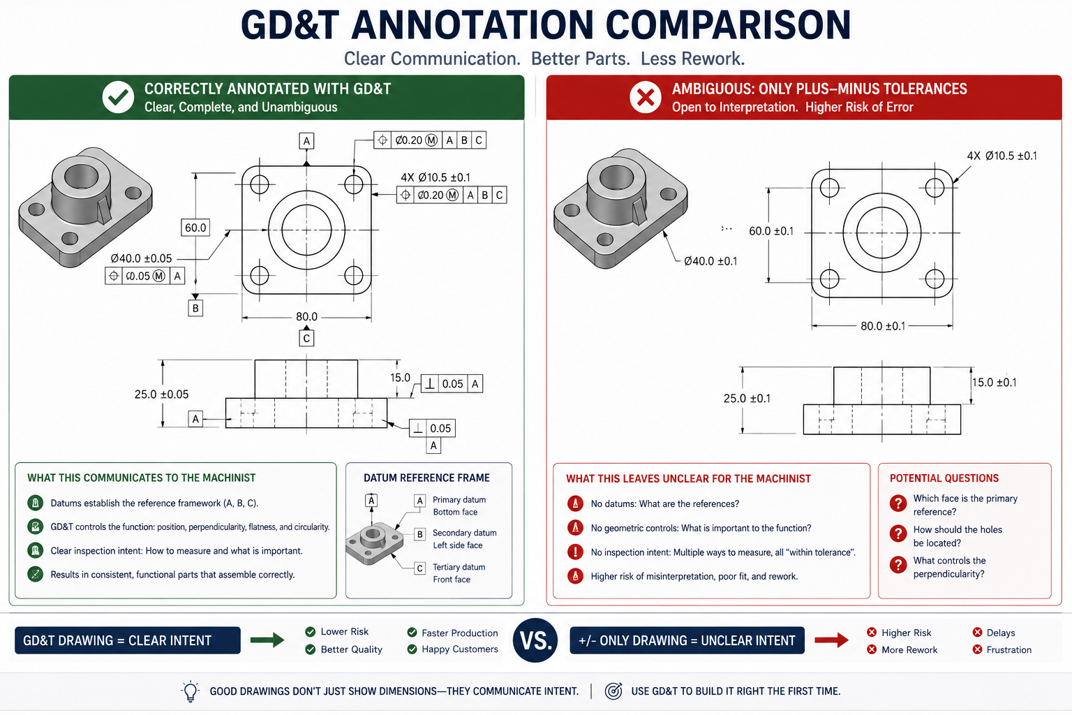
    Ambiguous or missing tolerancesGD&T and tolerancingManufacturer applies own judgment; parts fail assembly or inspectionApply ISO 2768-m as drawing default. Add explicit tolerances only where function requires them.
    Wrong or missing projection symbolDrawing standardViews read as mirrored; features on wrong faceAlways include the first-angle or third-angle projection symbol in the title block. Never omit it.
    Mismatched layer structureDrawing managementReviewer cannot separate structure from annotation; critical notes hidden on wrong layerUse a named layer standard file. Never draft on Layer 0. Assign line weights per layer.
    No general tolerance block in title blockDrawing completenessEvery undimensioned feature is ambiguous; manufacturer queries whole drawingAdd general tolerance reference (ISO 2768-mK or ASME equivalent) to title block on every drawing.
    Scale error in model spaceCAD setupBlocks and XREFs imported at wrong scale; printed dimensions do not match modelAlways draw at 1:1 in model space. Set viewport scale in layout. Mark NTS where applicable.
    Incorrect line weights and typesDrawing clarityHidden lines indistinguishable from visible; centre lines read as object linesAssign line weights through layers not individual entities. Follow ISO 128 or ASME Y14.2 line standards.
    No surface finish callout where requiredDrawing completenessManufacturer applies default finish; sealing or mating surfaces fail in serviceSpecify Ra value by zone: mating faces, sealing surfaces, general. Reference ISO 1302 or ASME B46.1.
    GD&T datum structure missing or inconsistentGD&T errorsInspection built on wrong reference; all positional measurements meaninglessDefine a three-plane datum reference frame. Apply datums consistently throughout all views.
    Single layer draftingDrawing managementImpossible to isolate discipline layers; collaboration, printing, and review all failMinimum layer set: Object, Hidden, Centre, Dimension, Annotation, Titleblock, Viewport. Never merge.
    No weld specification on welded assembliesFabrication documentationWeld size, type, and process left to fabricator judgment; structural integrity at riskApply AWS or ISO welding symbols to every weld joint. Specify process where it affects quality.
    File format incompatible with downstream toolFile managementFabricator cannot open DWG version; CNC controller cannot read STEP; programme delayedConfirm required format and version before release. Specify format in drawing notes or transmittal.
    No revision cloud on changed areasRevision managementReviewer cannot identify what changed; entire drawing re-checked; review time tripledAdd a revision cloud around every changed region. Log the change description in the revision table.

    What Each Type of Error Actually Costs: Discovery Stage vs Financial Impact

    The cost of a CAD drawing error is not fixed. It is determined almost entirely by the stage at which the error is discovered. The same missing dimension costs minutes to fix at the drawing stage and days of programme delay if it reaches the fabricator. This table puts real numbers on the cost spectrum for the most common error types.

    Error TypeDiscovery StageTypical Direct CostDelay Impact
    Missing dimensionQuoting stageEngineer time only: 0 to $200Hours: query and response turnaround
    Wrong units (mm vs inches)FabricationMaterial scrap plus rework: $500-$10,000Days to weeks: reorder and remake
    Outdated revision issuedPost-fabricationFull part batch scrapped: $5,000-$100,000+Weeks to months: tooling and remanufacture
    Wrong projection (1st vs 3rd angle)FabricationFeatures on wrong face: complete rejectionWeeks: remake of entire batch
    Missing tolerance on critical fitAssemblyReassembly or selective fitting: $1,000-$50,000Days to weeks: 100% inspection and rework
    File format incompatibleBefore fabricationConversion time: $0-$500Hours to days: format conversion or resupply
    Weld not specifiedPost-inspectionWeld rework or full re-fab: $2,000-$30,000Days to weeks: weld repair programme
    Surface finish missing on seal faceIn-service failureWarranty claim or field rework: $10,000+Weeks: field intervention plus investigation

    These ranges are conservative estimates based on published industry case studies and fabrication cost benchmarks. On larger programmes with multiple trades, the cascade effects of a single drawing error can multiply these figures significantly when downstream trades are waiting on the affected component.

    Error Cost vs Discovery Stage Before and After Bar Chart Common CAD Drafting Mistakes
    The engineering principle is the same at both stages. The economics are not.

    Missing and Incomplete Dimensions: The Most Frequent Delay Trigger

    Missing or incomplete dimensions are the single most reported engineering drawing error category across manufacturing, construction, and infrastructure sectors. They are also the most preventable because their absence is, in principle, detectable by anyone who checks the drawing systematically.

    The practical reason they persist is that engineers check drawings for correctness of what is there, not for completeness of what should be there. A drawing review that confirms every stated dimension is correct can still miss three dimensions that should have been stated but were not. The prevention requires a different type of check: a systematic audit of every feature against what is required for manufacture.

    Dimension Error TypeWhat a Manufacturer Cannot Do Without ItPractical Fix
    Missing linear dimension on a featureCannot set up machine to correct depth, width, or heightDimension audit: every feature must have at least one dimension defining each axis of extent
    Missing hole depth calloutDrills blind hole to default or to judgment; may break throughUse depth symbol with every blind hole callout. Specify depth from which face.
    Missing thread specificationTaps wrong thread standard or pitch; fastener will not engageCallout must include standard, nominal diameter, and pitch (M12x1.75 or 1/2-13 UNC)
    Conflicting dimensions on same featureMust choose one; chooses incorrectly; both can be wrongRemove driven dimensions or reference them explicitly. Check all views show consistent values.
    Reference dimension unmarkedTreated as production dimension; inspected; fails unnecessarilyMark all reference dimensions as REF or in parentheses (50) so manufacturer knows intent.
    Tolerance on non-critical feature too tightManufacturer applies premium process; cost uplift with no benefitAudit every tolerance. Ask: does function change if this is at the wrong end of its tolerance range?
    No GD&T on a feature that requires itSize tolerance controls nothing about form or positionApply GD&T where form, orientation, or position matters for assembly or function.

    The Dimension Audit Method

    A dimension audit is a feature-by-feature check of the drawing against the question: if a machinist builds this feature from this drawing alone, without reference to the 3D model, do they have everything they need? For each feature, identify: what defines its location in X, Y, and Z, what defines its size in every relevant direction, what defines its angular orientation where it is not parallel to a reference plane, and what defines its depth or extent.

    Any feature for which any of these questions cannot be answered from the drawing has a missing dimension. The audit takes five to fifteen minutes on a typical mechanical part drawing. The rework it prevents can save days of programme delay.

    The ‘machinist test’ for dimension completeness:  Before releasing any drawing, ask yourself: if I handed this drawing to a skilled machinist with no access to the 3D model, no access to me, and no ability to ask questions, could they build this part exactly as intended? Every gap in that scenario is a missing dimension or specification that needs to be added before the drawing is released.

    Unit and Scale Errors: Small Oversight, Catastrophic Consequence

    Unit errors are among the most expensive single drafting mistakes in manufacturing. A part designed in millimetres that is cut in inches is 25.4 times larger than intended. A part designed in inches that is cut in millimetres is 25.4 times too small. The material is scrapped entirely. The order is repriced. The lead time restarts from zero.

    The reason these errors happen is structural, not careless. CAD software assumes a unit system and does not always enforce it visibly. When drawing files are shared between teams using different unit conventions, the units embedded in the file may not match the units the recipient expects. An engineer who opens a file, checks the geometry looks right on screen, and proceeds without checking the unit setting is working from an assumption that may be wrong.

    How to Eliminate Unit Errors Permanently

    1. Use a company-standard drawing template (DWT file) with units set correctly for your primary manufacturing context. Every new drawing created from this template inherits the correct units automatically.
    2. Check INSUNITS before inserting any external block or XREF. The INSUNITS variable controls how the CAD software scales inserted content. Mismatched INSUNITS between the source file and the destination file cause scale errors on insertion.
    3. State the unit system explicitly in the title block. Millimetres or inches. Never leave it implicit. The title block statement is the authoritative reference for anyone who reviews or uses the drawing.
    4. Add a dimension of a known element to a new import as a first check. If an imported block shows 25mm where you know it should show 1 inch (25.4mm), the units have mismatch. Catch it immediately, not after the drawing is built around the wrong scale.
    The unit error that keeps happening:  A steel plate designed in AutoCAD in metric units is exported to DWG and opened by a contractor working in an imperial-unit environment. The plate appears at the correct proportional size on screen because AutoCAD scales intelligently, but the file’s internal units are now ambiguous. The fabricator cuts to the dimensions on screen. The plate is 25.4 times too small. This exact sequence is one of the most consistently reported manufacturing disasters from cross-border drawing sharing. The fix is one line in the title block and one INSUNITS check.

    Outdated Revisions on the Shop Floor: The Error That Cannot Be Unseen

    Of all the common drafting errors covered in this guide, issuing an outdated drawing revision to the manufacturing floor is the one with the most consistently catastrophic consequences. When a fabricator builds from a superseded design, the error is invisible until the part either fails to fit, fails inspection, or fails in service. By that point, the material is consumed, the machining time is spent, and the programme impact is measured in weeks, not days.

    Why Outdated Revisions Keep Reaching Manufacturing

    The root cause is almost always a distribution problem rather than a revision control problem. The revision table on the drawing is correctly maintained. The drawing number is correct. But the drawing that reaches the fabricator is a copy from a previous issue, saved to a personal drive, an unmanaged shared folder, or an email attachment that predates the current revision.

    The fabricator has no way of knowing the drawing is outdated because it looks identical to the current drawing in every visible respect. The only difference is the revision letter in the title block, which is easy to overlook if the process for checking revision currency before fabrication is not enforced.

    The Three-Part Revision Control System

    • Revision control block on every sheet: Current revision letter, change description, date, and approver name visible in the title block on every sheet of a multi-sheet drawing set. If sheet 3 carries a different revision from sheet 1, the set is not coherent and must not be issued.
    • Single-source distribution: One controlled location where fabricators and site teams access drawings. Any copy of a drawing outside this controlled source is a liability. Archive superseded revisions with a clear SUPERSEDED watermark or move them to a separated archive folder.
    • Transmittal acknowledgement: When a revised drawing is issued, the transmittal record documents who received it, which revision, and on what date. This creates an auditable chain of custody and eliminates the ‘I did not receive the updated drawing’ dispute at the root cause.

    Tolerance Errors: The Silent Cause of Failed Assemblies

    Tolerance errors in CAD drawings fall into two categories that cost in opposite directions. Over-specified tolerances add cost and lead time without improving function because they require premium machining processes and 100 percent inspection of features that do not need precision control. Under-specified tolerances, or no tolerances at all, allow parts to be made within a range that prevents correct assembly or function, leading to selective fitting, rework, or rejection.

    Both types of tolerance error are extremely common. A 2026 industry analysis by Printform identified incomplete GD&T and inconsistent tolerance application as one of the three most programme-impacting error categories in mechanical CAD design. The consistent pattern is engineers applying tight tolerances by default to all dimensions, or applying no GD&T at all and relying on plus/minus values that do not control form or position.

    The Tolerance Strategy That Prevents Both Problems

    The correct approach is selective tolerancing: apply tight tolerances only to features that genuinely require them for assembly or function, and let all other features default to a general tolerance standard. In practice, this means two steps before any drawing is released.

    First, add a general tolerance block to the title block referencing ISO 2768-m (for ISO drawings) or the equivalent ASME general tolerance note. This covers all undimensioned and unlabelled features with a documented default. Second, go through every dimension that carries an individual tolerance and ask: does the function of this assembly change measurably if this dimension is at the opposite end of its tolerance range? If yes, the tolerance is justified. If no, replace the individual tolerance with a general tolerance reference.

    This approach removes the cost of precision machining from features that do not require it, concentrates quality control effort on the features that genuinely matter, and communicates to the manufacturer which features are critical and which are not.

    The Pre-Release Drawing Checklist: 13 Checks Before Every Issue

    The majority of engineering drawing mistakes that cause manufacturing delays are detectable by a structured pre-release check. The following checklist addresses the most common error categories systematically. Build it into your drawing release workflow as a mandatory gate before any drawing is issued to manufacturing, procurement, or a client.

    General tolerance stated | All features dimensioned | Tolerances selective and correct | Projection symbol present | Surface finish specified | Weld symbols on all joints | GD&T datum structure defined | Revision cloud on all changes | Layer structure correct | File format confirmed compatible | Drawing standard stated | Peer review completed.
    This checklist takes three minutes to complete. It prevents rework that takes three weeks to fix.’
    Pre-Release CheckWhat to Verify
    Title block completeDrawing number, revision, date, scale, units, projection symbol, approval signature all populated
    General tolerance statedISO 2768-m or ASME equivalent in title block; no drawing issued without a general tolerance reference
    All features dimensionedEvery feature a manufacturer needs to produce is dimensioned; no feature defined by scale alone
    Tolerances selective and correctTight tolerances on mating and functional interfaces only; general tolerance everywhere else
    Projection symbol presentFirst-angle or third-angle symbol visible in title block; never omitted
    Surface finish specified by zoneRa value on all sealing, mating, and cosmetic surfaces; general finish in notes for remaining surfaces
    Weld symbols on all jointsEvery joint that will be welded carries the correct AWS or ISO symbol with process note where relevant
    GD&T datum structure definedPrimary, secondary, tertiary datums established and consistently referenced throughout all views
    Revision cloud on all changesEvery area changed from the previous revision is circled; revision table updated with description and date
    Layer structure correctAll content on named layers per convention; nothing on Layer 0; line weights assigned through layers
    File format confirmed compatibleFormat and version match the downstream requirement; INSUNITS set correctly before any XREFs inserted
    Drawing standard statedGeneral note referencing ASME Y14.5-2018, ISO 1101, or equivalent; standard clear to any reader
    Peer review completedA second engineer has checked the drawing; checker name and date in title block or review record
    The two-minute check that prevents two-week delays:  Print this checklist or keep it on your second monitor. Before issuing any drawing, run through every item. Cross off each one as you confirm it is present and correct. If any item cannot be crossed off, the drawing is not ready to issue. The checklist takes two minutes. The rework it prevents takes days or weeks.

    GD&T Errors: When Geometry Looks Right but Cannot Be Inspected

    Geometric Dimensioning and Tolerancing errors occupy a specific category of CAD drafting mistake because their consequences are not always visible at fabrication. A part made to a drawing with incorrect GD&T may be dimensionally correct by the manufacturer’s interpretation but fail inspection under the correct interpretation, or pass inspection and then fail to assemble correctly because the GD&T should have controlled a form error that the manufacturer did not realise was significant.

    The Most Common GD&T Drafting Errors

    • No datum reference frame: GD&T callouts for position, orientation, and runout are all meaningless without a defined datum structure. A positional tolerance of 0.2mm means nothing unless it is stated relative to a specific datum. Define primary, secondary, and tertiary datums that correspond to how the part will be fixtured and inspected.
    • Datum letters not consistent across views: Datum A references one face in the front view and appears to reference a different face in the right side view due to unclear label placement. Inspection builds on the wrong surface. All positional measurements are invalid.
    • Mixing ASME and ISO GD&T symbols: Concentricity is deprecated in ASME Y14.5-2018 but valid in ISO 1101. Using it on an ASME drawing creates an undefined callout. The drawing standard must be stated and symbols must be sourced from that standard alone.
    • GD&T applied where plus/minus is sufficient: Adding unnecessary feature control frames to every dimension adds complexity without adding information. GD&T should be applied where form, orientation, or position genuinely needs controlling beyond what a size tolerance provides.
    • Feature control frame referencing non-existent datum: The positional callout references datum D, but datum D is not labelled anywhere on the drawing. The manufacturer cannot inspect the feature to the stated control. The drawing must be re-issued before inspection can proceed.

    Layer Structure and File Management Errors: The Hidden Source of Review Time

    Layer management errors and file management mistakes do not always cause physical manufacturing problems, but they consistently cause review delays, collaboration failures, and the kind of confusion that makes a drawing set difficult to use efficiently. In an outsourcing or multi-discipline environment, a drawing with disorganised layers adds rework time at every stage of review, coordination, and update.

    Single-Layer Drafting: The Most Persistent Bad Habit

    Drawing all content on a single layer (or on Layer 0 in AutoCAD) is one of the most widespread CAD drafting mistakes in practice and one of the most difficult to correct retroactively. When all content is on a single layer, it is impossible to isolate object lines from annotations, to hide dimension layers for presentation, to control line weights by layer, or to extract specific content for coordination or fabrication.

    The minimum layer set for a mechanical drawing is: Object (visible geometry), Hidden (hidden lines), Centre (centre lines and axes), Dimension (dimension lines and text), Annotation (notes, leaders, hatching), Titleblock (title block content), Viewport (viewport borders in layout space). Every element on the drawing belongs to exactly one of these layers. No element should ever be on Layer 0 in a drawing issued for production.

    File Format and Version Incompatibility

    Specifying or delivering the wrong file format or wrong software version is a drafting workflow mistake that is entirely preventable and entirely common. The three most frequent situations: a DWG file saved in a newer format than the recipient’s software can open, a STEP file exported with the wrong geometry kernel for the recipient’s CAD system, and a PDF that is a rasterised image rather than a vector file, making text and dimensions unsearchable and non-scaleable.

    The prevention is a one-line confirmation: ask the recipient what format and version they require before the first file is delivered. State the required format in the drawing transmittal. For recurring partners, include format requirements in your CAD drawing specification document.

    How AI and DFM Tools Are Catching CAD Drafting Errors in 2026

    The category of CAD drawing errors that AI and automated DFM tools are most effective at catching in 2026 is geometric manufacturability violations: internal corners too tight for available tooling, pocket depths exceeding standard tool reach, walls lacking required draft angles, holes too close to bends. These are systematic, rule-based errors that human reviewers consistently miss because they are focused on technical content rather than process compliance.

    ToolWhat it checksCAD integration2026 status
    DFMXpress (SolidWorks)DFM violations: corner radii, draft, hole ratiosNative in SolidWorksBuilt-in, available to all SW users
    Fusion 360 DFM workspaceMachining, 3D printing, and sheet metal rulesNative in Fusion 360Active development, cloud-connected
    CoLab AutoReviewDrawing best practices, standard complianceBrowser-based, no CAD requiredComment on 3D models; emerging tool
    Xometry Instant DFMCNC, moulding, printing manufacturabilitySTEP file upload, cloudReturns feedback with quote instantly
    Autodesk Forma / ACCClash detection, coordination checkingCloud BIM environmentFor architecture and civil, not mechanical
    InfinitFormActive geometry optimisation for DFMFusion 360 and SolidWorksAutomated fix, not just flag
    GD&T AdvisorGD&T completeness and consistencyEmbedded in PTC CreoSpecialist GD&T checking tool

    What AI Tools Cannot Catch

    AI DFM tools in 2026 are strong on geometric rules and process compliance. They are weak on intent. A drawing that is geometrically manufacturable but functionally wrong, where the correct dimension was entered but the feature is in the wrong location relative to the datum, will pass most automated checks and fail only when the part is assembled. This category of error still requires human peer review.

    The most effective quality system in 2026 combines automated first-pass checking for geometric and format compliance (using DFMXpress, Xometry, or similar tools) with mandatory human peer review for technical content, and a structured pre-release checklist as the final gate before issue. Each layer catches what the others miss.

    Building Habits That Prevent CAD Drafting Mistakes

    The majority of common drafting errors are not caused by a lack of knowledge about what is correct. They are caused by habits, by defaults that were set up incorrectly long ago, by time pressure that shortcuts review, and by the absence of a system that makes the correct practice the path of least resistance.

    Use a Drawing Template, Not a Blank File

    Every engineering drawing should be started from a company-standard template that pre-configures units, projection method, title block, layer structure, text styles, dimension styles, and general tolerance reference. A blank file requires the engineer to set all of these correctly each time. A template makes the correct configuration automatic.

    A well-built DWT template file in AutoCAD, or a drawing template in SolidWorks, Revit, or Civil 3D, eliminates the unit setup error, the missing title block, the wrong projection symbol, and the default layer problem in one action. It is the single highest-leverage investment against systematic CAD drafting mistakes.

    Make Peer Review Non-Negotiable

    Industry data is unambiguous on this point: drawings reviewed by a second engineer before issue have significantly fewer drafting errors reaching manufacturing than drawings reviewed only by the drafter. The peer reviewer does not need to check every dimension for technical correctness. They need to run through the pre-release checklist and verify that the drawing is complete and internally consistent.

    In organisations where peer review is consistently applied, the rate of engineering drawing errors reaching manufacturing falls significantly. In organisations where it is treated as an optional step to be skipped under schedule pressure, the same errors recur in every batch of rework.

    Treat the Drawing as a Manufacturing Instruction, Not a Visual Record

    The most powerful mental shift for eliminating CAD drafting mistakes is to change how you think about what a drawing is. It is not a visual record of a 3D model. It is a manufacturing instruction set. Every element on the drawing is there to tell the manufacturer something they need to know. Every element that is missing prevents the manufacturer from knowing something they need to know.

    If an element on the drawing would not help a skilled machinist build the part correctly, it probably does not need to be there. If an element that would help the machinist is not there, it needs to be added. That single question, ‘what does this manufacturer need to know and have I told them?’, is the foundation of every effective drawing review.

    Conclusion:

    The CAD drafting mistakes covered in this guide are not the result of inadequate engineering skill. They are the result of process gaps: no template, no pre-release checklist, no peer review, no revision distribution system. Every one of them is preventable with a structured approach that takes less time to apply than the rework it prevents.

    The statistics are consistent: approximately 29 percent of project reworks start with simple drafting errors. The cost multiplier between fixing a drawing error at the CAD stage versus fixing it after fabrication is measured in orders of magnitude. The prevention investment, a proper template, a 13-item checklist, a peer review gate, and a revision distribution protocol, is measured in engineering hours per project.

    Start with the checklist. Apply it to the next drawing you release. Identify which items you are currently not checking. Those gaps are where your manufacturing delays are coming from.

    The drawing is the instruction. Write it so clearly that the manufacturer can follow it without stopping to ask a single question.

    Frequently Asked Questions

    What are the most common CAD drafting mistakes that cause manufacturing delays?

    The most common CAD drafting mistakes that cause manufacturing delays are: missing or incomplete dimensions that force the manufacturer to stop and query, incorrect or undefined units causing scale errors in fabrication, outdated drawing revisions issued to the shop floor, ambiguous or missing tolerances, missing projection symbols that cause views to be read as mirrored, and file formats incompatible with the downstream tool. Industry data shows approximately 29 percent of project reworks in design teams come from simple drafting errors.

    How do missing dimensions on a CAD drawing cause manufacturing delays?

    Missing dimensions cause manufacturing delays because the fabricator cannot proceed without knowing the exact size of a feature. When a dimension is missing, the standard workflow is to raise a query to the engineer, wait for the response, receive a revised drawing, and then begin fabrication. This cycle typically costs one to five days. On time-critical projects, a single missing dimension can push a part off a machine schedule entirely, adding weeks to the programme if the machinist’s capacity is allocated and cannot be immediately recovered.

    Why do wrong units in a CAD drawing cause such expensive problems?

    Wrong units in a CAD drawing cause expensive problems because the scale error is invisible until the fabricated part is measured or assembled. A part designed in millimetres and cut in inches is 25.4 times the intended size. A part designed in inches and cut in millimetres is 25.4 times too small. The material is scrapped, the order must be repriced, the lead time restarts, and the programme delay can range from days to weeks depending on material availability. Industry case studies consistently cite unit errors as one of the most expensive single-drawing mistakes.

    What is the difference between a drafting error and a design error in CAD?

    A design error is a technical decision that is wrong: the part will not function, the assembly will not fit, or the structure will not carry the load. A drafting error is a documentation error: the design intent is correct but the drawing fails to communicate it accurately to the manufacturer. A missing dimension is a drafting error. A hole in the wrong position is a design error. Both cause manufacturing delays, but drafting errors are generally cheaper to fix at the drawing stage and more expensive to catch after fabrication because they are easy to overlook during design review.

    How do I prevent outdated CAD drawings from reaching the manufacturing floor?

    Preventing outdated drawings from reaching the manufacturing floor requires three practices. First, a drawing distribution system where only the current approved revision is accessible to the manufacturing team, with older revisions archived and clearly marked as superseded. Second, a revision control block on every drawing sheet showing the current revision letter, change description, date, and approver. Third, a document transmittal process where every drawing issue is logged, dated, and acknowledged by the recipient, so there is an auditable record of who received which revision and when.

    Can AI tools catch CAD drafting mistakes before drawings are released?

    Yes. AI and automated DFM tools in 2026 can catch many common CAD drafting mistakes before drawings are released to manufacturing. DFMXpress in SolidWorks checks for geometric manufacturability violations. Xometry’s Instant DFM returns manufacturability feedback at the same time as a quote. CoLab AutoReview checks drawings against best practice standards. InfinitForm actively corrects geometry rather than just flagging it. These tools do not replace peer review, but they catch the systematic and geometric errors that human reviewers tend to miss because they are focused on technical content rather than drawing compliance.


    Printform 2026: the top 10 CAD design mistakes that delay manufacturing’

  • How to Write a Proper CAD Drawing Specification for Your Outsourcing Partner

    How to Write a Proper CAD Drawing Specification for Your Outsourcing Partner

    60%  cost saving reported by engineering firms outsourcing CAD drafting to specialist providers vs maintaining equivalent in-house capacity (C-Design, 2026)
    3-4x  higher cost of an in-house CAD and BIM team in the US or UK compared to specialist outsourcing, per published 2026 industry benchmarks
    Go-by set  the single most effective tool for reducing rework on outsourced drawings, per leading providers who make it a mandatory first step
    Free pilot  the most credible outsourcing partners offer a no-charge pilot on a representative sample before any volume commitment is made

    Introduction:

    Outsourcing CAD drawing work is a legitimate and increasingly common strategy for engineering teams in 2026. The cost advantage is real. Access to specialist skills is real. The ability to scale without permanent headcount is real. What is also real is the pattern of what happens when the briefing is done informally.

    An engineer sends a sketch, a PDF of an old drawing, and a brief email. The outsourcing partner, skilled and capable, produces drawings based on what they understood from those inputs. The drawings arrive. They are technically competent but in the wrong style, wrong file format, wrong drawing standard, with a title block the client has never seen, and layer names that make no sense in the client’s drawing management system.

    None of that is the partner’s fault. They were not told what was required. They applied their defaults. The rework is expensive and entirely avoidable, caused by the absence of a proper CAD drawing specification at the start of the engagement.

    This guide explains what a drawing specification must contain, how to use go-by drawings to communicate what a written document cannot, how to structure a pilot project that genuinely tests a partner before you commit production volume, and the mistakes that cause rework even when everyone involved is competent.

    Quick answer:  A CAD drawing specification for outsourcing is a written document defining the drawing standard, CAD software and version, file delivery formats, layer naming, title block requirements, revision protocol, and quality acceptance criteria. Without it, every assumption your partner makes is a potential source of rework. Provide go-by drawings alongside it to communicate style and quality that words alone cannot capture.
    How to Write a Proper CAD Drawing Specification for Your Outsourcing Partner
    A verbal briefing produces verbal results. A complete specification package produces drawings that match your standards from day one.

    Why a Written Specification Is Not Optional

    Every gap in the briefing becomes an assumption. Every assumption your partner makes that differs from your expectation becomes rework. The disciplines that benefit most from documented specifications are also the ones where rework is most expensive: mechanical drawing packages for manufacturing, structural drawing sets for construction, and MEP coordination drawings where errors propagate across multiple trades.

    What Happens Without a Specification

    • The partner applies their default drawing standard. If they work to ISO and your manufacturing base works to ASME, the GD&T interpretation is immediately wrong.
    • The partner uses their own title block template. Your drawing register uses a specific format. Every drawing must be recreated, not just corrected.
    • The partner uses their preferred layer naming convention. New drawings cannot be integrated with your existing archive without a conversion exercise.
    • The partner selects the file format they use most. If they deliver DWG 2024 and your CNC software requires DWG 2018, every file must be individually converted.
    • The revision protocol is improvised. Mark-ups go by email. Three revisions in, neither party has a reliable audit trail.

    Each problem is entirely preventable with a written drawing specification document provided before any work begins.

    What Your CAD Drawing Specification Must Contain

    A complete CAD drawing specification covers three categories: technical standards governing what the drawing contains, format requirements governing how files are delivered, and process requirements governing how work is managed. Missing any category produces avoidable rework.

    Specification ItemWhat to State PreciselyWhy It Matters If Missing
    Drawing standardASME Y14.5-2018, ISO 1101:2017, or DIN EN ISO equivalentPartner applies wrong GD&T defaults; form controls misinterpreted
    CAD software and versionSolidWorks 2025, AutoCAD 2026, Revit 2026, NX 2312Incompatible file format or missing features if version differs
    Deliverable file formatsDWG, STEP, PDF/A, IFC, native format, or combinationsWrong format blocks downstream workflow with manufacturer or client
    Sheet size and orientationASME A-E or ISO A4-A0, landscape or portrait per sheetPrinted sets misaligned; PDF pagination incorrect for review
    Title block templateProvide your template file; specify required fieldsPartner creates own title block; branding and fields are wrong
    Layer naming conventionProvide layer standard file or reference documentLayer chaos makes file management and overlay work impossible
    Line weights and typesSpecify or provide a line weight tableDrawings look inconsistent; printed output does not match standard
    General tolerance standardISO 2768-mK or ASME title block tolerance noteAmbiguous tolerances lead to over- or under-constrained parts
    Projection methodThird-angle (ASME) or first-angle (ISO)Views misread as mirrored; wrong features on wrong faces
    UnitsMillimetres, inches, or mixed (state clearly)Dimensional errors from unit conversion if mixed unwittingly
    Scale convention1:1 default; NTS where stated; scale bar requiredPrinted drawings used for measurement; wrong parts made
    Revision control systemRevision letter sequence, revision table format, ECN refRevision history lost; old revisions used in production
    Numbering and drawing registerPart number format, drawing number format, BOM numberingMismatched part numbers between drawing and procurement
    BOM format and contentRequired columns, hierarchy, link to drawing numbersBOM does not match drawing; procurement builds wrong assembly
    Confidentiality levelProprietary, controlled distribution, or openIntellectual property risk if unmarked drawings are shared

    The Drawing Standard Declaration

    This is the single most technically consequential element. State the standard by name and year: ASME Y14.5-2018, ISO 1101:2017, or DIN EN ISO 2768-mK. If your drawings use multiple standards, state each separately with a clear note about which governs which element.

    The Scope Document: Structure That Prevents Disputes

    Alongside the technical specification, provide a scope document defining the commercial and process boundaries of the engagement.

    Document SectionWhat It Must ContainCommon Gap If Missing
    Project overviewWhat is being designed, industry context, end usePartner draws without understanding function; misses safety-critical features
    Deliverable listEvery drawing type, quantity, and format requiredDrawing types or formats missed; argument about scope at invoice
    Input documentsGo-by drawings, sketches, models, specifications providedPartner works from memory or assumptions; wrong style or standard
    Drawing standard referenceStandard name, year, and which elements it governsPartner applies default standard; GD&T and projections conflict
    Software requirementsSoftware name, version, required plugins or templatesFile compatibility issues at delivery; cannot open without conversion
    Timeline and milestonesSubmission date per batch, review period, revision deadlineNo accountability; delivery slips without contractual reference
    Revision protocolHow mark-ups are sent, turnaround time, back-redline reqRevision cycles become unstructured; changes get lost or duplicated
    Quality check requirementWhat QA the partner must perform before submissionUnchecked errors submitted; review burden falls entirely on client
    Communication protocolPrimary contact, escalation path, response time SLACommunication gaps; decisions made without documentation
    IP and confidentialityNDA status, marking requirements, data security standardIntellectual property risk; no contractual protection if breach occurs
    Acceptance criteriaWhat constitutes a complete and acceptable deliverableDisputes about quality at completion; rework without clear definition

    Go-by Drawings: The Most Effective Tool in Your Specification Package

    A specification document tells a partner what you require. Go-by drawings show them. Leading CAD outsourcing providers ask for go-by drawings before beginning any work because a written description of dimension text height 3.5mm with closed filled arrowheads is not as unambiguous as a drawing where the engineer can see exactly what those requirements produce visually.

    Go-by drawing elementWhat it communicates to your outsourcing partner
    Title block layout and field positionsExactly which field goes where, how your company name and logo appear, what the revision table looks like
    Layer naming and colour assignmentsThe visual hierarchy of the drawing; what is visible in which colour on screen and in print
    Line weight hierarchyWhich features print heavy (object lines), medium (hidden), or fine (centre lines, dimension lines)
    Text height and fontAnnotation style throughout: dimension text, note text, title text, table text
    Dimension style and arrow typeClosed filled arrows vs open arrows; leader line style; tolerance annotation format
    View layout and spacingHow views are arranged on the sheet; spacing between views; section label placement
    General notes format and contentStandard notes your drawings carry: projection symbol note, general tolerance note, surface finish default
    BOM table formatColumn headers, row spacing, part number format, quantity and unit format
    Revision table formatColumn headers, revision letter format, description field length, approval field
    Section and detail view labellingHow section cuts are labelled (A-A, B-B), how detail enlargements are referenced
    Weld symbol and GD&T callout styleHow feature control frames are placed; leader line and flag note conventions

    How to Select Good Go-by Drawings

    The best go-by drawings are: technically complete with no missing information, representative of the complexity of work the partner will produce, free of known errors that crept in under schedule pressure, and recently produced to reflect your current standards. Provide at least two to three go-by drawings covering different drawing types and complexity levels.

    Go-by drawing rule:  Redact proprietary dimensional information from go-by drawings before sending if they show commercially sensitive products. Replace specific dimensions with representative values while keeping all stylistic and format information intact. The partner needs to see how the drawing is built, not the exact dimensions of the product.

    The Pilot Project: Testing a Partner Before Committing Volume

    A pilot project is the most reliable way to discover whether a partner can genuinely meet your specification before you commit significant volume. Every credible outsourcing provider offers pilot work, and many offer it at no charge because they understand it is the normal due diligence step before a production relationship begins.

    Pilot phaseWhat to includeWhat you are testing
    Scope selectionOne to three drawings of moderate complexityReal capability, not a showcase best effort on an easy drawing
    Full spec provisionProvide your complete specification, templates, and go-by drawings as if for full productionWhether partner can absorb and apply your standards correctly
    Defined timelineSet the same turnaround expectation as production; do not give extra timeReal delivery performance, not a padded demonstration
    Structured reviewReview against your specification point by point; document every findingWhether partner quality matches your requirement, not just your impression
    Revision roundIssue one complete set of mark-ups; request back-redlined copy with changes highlightedRevision discipline: how thoroughly and accurately changes are applied
    Communication logNote response times, question quality, escalation handling across the pilot periodWhether working relationship will be productive at scale
    Go/no-go decisionSet explicit criteria before the pilot; do not grade on a curve at the endWhether this partner can safely receive production work

    Evaluating the Pilot

    The pilot review should answer four questions. Did the partner apply your specification correctly without constant reminders? Are the drawings technically complete and accurate, not just visually correct? How did they handle gaps in the specification that required judgment? And was the revision round productive, with changes applied completely and a back-redlined copy returned? The go/no-go decision should be based on objective criteria defined before the pilot begins, not on a general impression.

    Defining Your Revision Protocol

    The revision protocol governs how changes are communicated between your team and the outsourcing partner. Without a documented protocol, mark-up cycles become an email chain where changes get applied partially and both parties lose track of the current revision state.

    • Mark-up format: Annotated PDF, redlined DWG, numbered comment list, or cloud review tool. State the format and provide a template.
    • Turnaround time: 24 hours, 48 hours, or by a named date. State it explicitly.
    • Back-redline requirement: After implementing changes, the partner should return a back-redlined copy showing exactly what changed. This confirms the mark-up was understood and applied completely.
    • Revision letter protocol: What triggers a revision letter increment? State it in advance.
    • Scope of change vs new drawing: When is a change large enough to become a new drawing? Define the threshold.
    The back-redline rule:  Always require a back-redlined copy after every revision round. A partner who returns a clean updated drawing without a back-redline cannot prove every mark-up was addressed. This single practice eliminates the majority of revision disputes.

    Quality Assurance: What to Require Before Submission

    Every drawing your outsourcing partner submits should have passed their own internal quality check before it reaches you. Specifying what that check must cover transfers the first-pass review burden to the partner.

    QA check itemWhat the partner should verify before submission
    Drawing standard complianceGD&T symbols, datum notation, and projection method match the stated standard
    Title block completenessAll mandatory fields populated: drawing number, revision, date, scale, units, approval
    Layer complianceAll content on correct layers per naming convention; no content on Layer 0 or default layers
    Revision table accuracyRevision letter, description, date, and approver fields match the current revision and change log
    BOM accuracy vs drawingEvery part called out on the drawing appears in the BOM with correct quantity and description
    Dimension completenessEvery feature required for manufacture is dimensioned; no features defined only by scale
    Tolerance consistencyNo dimension lacks a tolerance where one is required; general tolerance reference in title block
    View completenessAll referenced views exist on the sheet or a named sheet; all section cuts reference their views
    File format deliveryAll required formats delivered (DWG, PDF, STEP etc.); file naming matches drawing register convention
    Scale accuracy (model space)Model drawn at 1:1 in model space; viewports set to specified scales; NTS noted where applicable
    Spell check and nomenclatureNotes, labels, and BOM descriptions spell-checked; terminology consistent with client standards
     Revision Cycle Workflow in CAD Drawing Specification
    A documented revision cycle with back-redline requirement eliminates the most common revision disputes.

    Intellectual Property and Data Security

    When you outsource CAD drawings, you share information about your products, designs, and clients with a third party. That information needs legal and procedural protection before it is shared, not after a breach has occurred.

    The NDA: Sign Before You Brief

    A Non-Disclosure Agreement should be signed before any project information is shared, including during scope discussions and before providing go-by drawings. Make it a standing rule: NDA first, then specification, then go-by drawings, then project briefing.

    Drawing Confidentiality Markings

    Every drawing sheet should carry a confidentiality marking: PROPRIETARY, CONFIDENTIAL, or CONTROLLED DISTRIBUTION. Specify the required markings in your drawing specification and provide a template that includes them in the correct title block position.

    Data Security Requirements

    • File storage: State where project files must be stored. Prohibit storage on personal devices or consumer file-sharing services.
    • Access control: Who within the partner organisation may access the files?
    • Subcontracting: Is the partner permitted to pass work to subcontractors? Under what conditions?
    • File deletion: When and how are your files deleted at project end? Request written confirmation.
    • Software licensing: Confirm the partner uses fully licensed CAD software.
    The most common IP mistake in CAD outsourcing:  Providing go-by drawings and project sketches before the NDA is signed because the partner needs to see the scope to quote it. A responsible partner will sign the NDA before receiving any design information. If a prospective partner resists signing before the briefing, that is itself a red flag about their approach to client data.

    Managing the Outsourcing Relationship After It Starts

    Single Point of Contact

    Nominate one internal contact for all communication with the outsourcing partner. When multiple team members brief the partner independently, the partner receives conflicting instructions. The resulting drawings satisfy one internal stakeholder and disappoint another.

    Regular Output Review

    Do not wait for a large batch to be complete before reviewing quality. Schedule periodic light reviews of recent submissions against your specification. Drift happens gradually: a partner fully compliant at pilot end may begin taking shortcuts on elements rarely checked.

    Specification Version Control

    Treat the drawing specification exactly as you would treat an engineering drawing: version-control it, note what changed in each revision, and confirm the partner has received and understood the updated version before they produce work to it.

    10 CAD Outsourcing Briefing Failures That Produce Rework

    These are the patterns that appear most consistently when outsourced drawing quality falls short. Almost all trace back to something not specified at the start rather than any failure of partner capability.

    FailureWhat happensHow to prevent it
    Spec given verbally or by email threadPartner interprets differently; no audit trailAlways deliver a written specification document, not a call summary. Version control it.
    No go-by drawings providedPartner creates own style; training rework neededProvide go-by drawings before work starts. Allow no assumptions about style.
    Drawing standard not statedPartner applies their default; GD&T misinterpretedState the standard explicitly. ASME Y14.5-2018 or ISO 1101:2017.
    Software version not specifiedFile delivered in incompatible format or versionName the exact software and version. Include required plugins or template files.
    No pilot project runMisalignment discovered after full batch submittedAlways run a scoped pilot before committing full production volume to a new partner.
    Revision protocol undefinedMark-ups lost; changes applied inconsistentlyDefine revision turnaround, back-redline requirement, and mark-up format before work begins.
    NDA not signed before briefingIP disclosed before legal protection is in placeExecute NDA before any project information is shared, including during scope discussion.
    No acceptance criteria definedDisputes about what correct means at deliveryDefine acceptance criteria in the specification before work starts, not during review.
    Single point of contact not definedMultiple people brief partner inconsistentlyNominate one internal contact for all communication. Document this in the spec.
    No versioning on specification itselfSpec updated informally; partner works to old versionVersion-control your specification document. Treat it like an engineering drawing.
    The outsourcing briefing checklist:  Before assigning any work: (1) NDA signed. (2) Written specification provided and version-controlled. (3) Go-by drawings provided for all drawing types. (4) CAD template and layer standard files provided. (5) Pilot project scoped, run, and evaluated against objective criteria. (6) Revision protocol agreed. (7) QA checklist provided. (8) Single point of contact confirmed on both sides. (9) File format and software version confirmed compatible. (10) IP and data security requirements stated in writing. Ten items. All preventable rework if addressed before work begins.

    AI and Digital Collaboration Tools in CAD Outsourcing in 2026

    Cloud-based review platforms like Bluebeam Revu and Autodesk Construction Cloud allow mark-ups in a shared environment with every comment timestamped and tracked. AI-assisted review tools like CoLab AutoReview automate first-pass checks of submitted drawings against company standards. AI tools like Claude can draft a complete CAD drawing specification from a conversational description of requirements, reducing the time from ‘we need a spec’ to ‘the partner has it’ from days to hours.

    Conclusion:

    The quality of your CAD outsourcing relationship is determined before the first drawing is produced. It is determined by the completeness of the specification you provide, the relevance of the go-by drawings you include, the rigour of the pilot project you run, and the clarity of the protocols you define for revision, QA, and communication.

    Outsourcing partners in 2026 are generally capable. What they cannot invest in is your specific drawing standard, your specific title block, your specific revision convention, and your specific layer naming. That knowledge lives in your organisation and must travel to them in writing.

    A good specification is the contract between what you need and what you receive. Write it that way.

    Frequently Asked Questions

    What is a CAD drawing specification for outsourcing?

    A CAD drawing specification for outsourcing is a written document defining every technical, format, and process requirement your external CAD partner must meet. It covers the drawing standard, CAD software and version, file delivery formats, layer naming, title block requirements, general tolerance reference, revision control protocol, and quality acceptance criteria. Without it, every assumption your partner makes is a potential source of rework.

    What are go-by drawings in CAD outsourcing?

    Go-by drawings are representative examples from your existing drawing set provided to a partner as a visual reference for style, standard, and quality expected. They communicate what a written specification cannot: layer structure, line weights, text heights, dimension style, title block layout, and BOM format. A good go-by set covers a range of drawing types representative of the work the partner will produce.

    How do you run a pilot project with a new CAD outsourcing partner?

    A pilot project involves issuing one to three representative drawings to a new partner before committing full volume. Provide the complete specification, templates, and go-by drawings. Set the same timeline as production. Review output against your specification point by point. Issue one revision round and check whether all changes are applied correctly with a back-redlined copy returned. Define go/no-go criteria before the pilot begins.

    What file formats should I specify for CAD drawing outsourcing?

    File format for CAD drawing requirements depend on your downstream workflow. For manufacturing: DWG and PDF/A. For BIM coordination: Revit native plus IFC. For machining: STEP alongside 2D DWG. For sheet metal: DXF for flat patterns. Always specify the software version alongside the format because DWG from AutoCAD 2026 may not open correctly in AutoCAD 2019 without conversion.

    How do I protect my IP when outsourcing CAD drawings?

    IP protection requires three measures. First, a signed NDA before any project information is shared. Second, confidentiality markings on every drawing sheet. Third, data security requirements in the specification covering file storage location, access control, subcontracting restrictions, and file deletion procedures at project end.

    What should a CAD drawing outsourcing scope document contain?

    A scope document should contain: a project overview, a complete deliverable list, a list of input documents provided, the applicable drawing standard, software and version requirements, a timeline with milestones, the revision protocol, QA requirements the partner must perform before submission, communication protocols, IP and confidentiality requirements, and acceptance criteria defining what constitutes a complete and acceptable deliverable.


    ASME Y14.100: the engineering drawing practices standard governing drawing completeness and approval’

  • Engineering Drawing Standards: ASME, ISO, and DIN — What Is the Difference?

    Engineering Drawing Standards: ASME, ISO, and DIN — What Is the Difference?

    86%  of US engineering companies use ASME Y14.5 as their GD&T standard (Krulikowski survey, 133 respondents across 27 countries)
    56%  of non-US international companies also use ASME Y14.5, making it the most-used GD&T standard globally despite ISO GPS being the international standard
    100+  individual modular standards in the ISO GPS family, compared to approximately 17 documents in the ASME Y14 series
    R2024  ASME Y14.5-2018 reaffirmed in 2024, confirming it remains the current ASME GD&T standard. No new revision is in force as of 2026.

    Introduction:

    A machined shaft is designed in the United States under ASME Y14.5. The purchase order goes to a precision machinist in Germany who works exclusively to DIN EN ISO standards. The drawing arrives. The machinist reads the cylindricity tolerance as independently controlled, as ISO 8015 requires, and machines the shaft to those standards. The shaft arrives in the US. Inspection rejects it because under ASME’s envelope principle, the size tolerance was supposed to control the cylindricity automatically, and the part’s form errors fall outside what the ASME-reading inspector considers acceptable.

    Nobody did anything wrong. The drawing was correct. The machinist was correct. The inspector was correct. The problem was that the drawing did not state which engineering drawing standard governed its GD&T, and the two parties operated under different default assumptions about what the same symbols and tolerance values meant.

    This guide explains what ASME, ISO, and DIN drawing standards are, how they differ technically and philosophically, which industries and geographies use which, and what the specific conflicts are between standards that cause parts to be made or inspected incorrectly when engineers do not know which standard applies.

    Quick answer:  ASME Y14.5 is the US standard for GD&T and engineering drawings, using third-angle projection and the envelope principle by default. ISO GPS (ISO 1101 and related standards) is the international standard, using first-angle projection and the independency principle. DIN standards are German national standards that have largely been harmonised with ISO since the 1990s and are now cited as DIN EN ISO in most cases. All three must be explicitly stated in the drawing title block because mixing them without notation causes misinterpretation of tolerances and views.
    Engineering Drawing Standards ASME, ISO, and DIN
    Always check the projection symbol in the title block before reading any view on a drawing from an unfamiliar source.

    ASME, ISO, and DIN: What Each Standard System Actually Is

    ASME: The American Engineering Drawing Language

    ASME stands for the American Society of Mechanical Engineers, a non-profit professional organisation founded in 1880. Its Y14 series of standards defines how engineering drawings are produced and interpreted in the United States. The most important of these is ASME Y14.5, which defines GD&T: the symbolic language for communicating dimensional requirements and tolerances.

    ASME Y14.5 can trace its roots to MIL-STD-8, a US military standard from 1949. It was the wartime need for interchangeable parts produced at multiple facilities that drove the early development of formalised geometric tolerancing. The standard has been revised approximately every decade since the 1960s. The current version is ASME Y14.5-2018, reaffirmed in 2024 (designated R2024), confirming it remains in force. No newer revision is in effect as of 2026.

    The 2018 edition made two changes that every engineer working to ASME standards should know: it deprecated the concentricity and symmetry symbols, replacing them with positional or profile controls, and it explicitly incorporated Model-Based Definition (MBD), recognising that tolerances are increasingly embedded in 3D models rather than printed on 2D drawings.

    ISO GPS: The International Drawing Language

    ISO is the International Organization for Standardization, founded in 1947. Its ISO GPS system (Geometrical Product Specifications) is the international framework for engineering drawing standards, covering everything from line types (ISO 128) to surface texture (ISO 1302) to the full GD&T system (ISO 1101, ISO 8015, and over 100 related standards).

    Unlike ASME’s relatively consolidated Y14 series of around 17 documents, the ISO GPS system is modular and composed of more than 100 interrelated standards, each covering a narrow, specific aspect of geometric specification. ISO 1101 covers tolerancing symbols. ISO 8015 defines the fundamental rules. ISO 5459 covers datum references. ISO 14638 defines the masterplan for the GPS system. This modularity is both a strength, each standard can be updated independently, and a challenge, because understanding the full system requires familiarity with multiple documents.

    ISO GPS is the default standard in Europe, increasingly adopted in Asia, and the required standard for international supply chains that cross multiple regulatory jurisdictions. Its first-angle projection convention and independency principle for tolerancing represent fundamentally different default assumptions from ASME.

    DIN: The German National Standard

    DIN stands for Deutsches Institut fur Normung, the German Institute for Standardization, founded in 1917. DIN standards for engineering drawings have been through significant harmonisation with ISO since the 1990s as part of European standardisation efforts. The consequence is that most current DIN engineering drawing standards are designated DIN EN ISO, meaning they are the German national adoption of a European (EN) adoption of an International (ISO) standard.

    The practical meaning: DIN EN ISO 1101 is the same standard as ISO 1101 in technical content. DIN EN ISO 2768 is the same as ISO 2768. When a German supplier cites DIN EN ISO standards, they are working to the same technical requirements as any other ISO GPS user. The DIN-specific designation indicates the standard has been formally adopted as a German national standard, which carries regulatory significance in some procurement contexts.

    Where DIN remains genuinely distinct is in standards that have not been harmonised, such as DIN 7168 (German general tolerances, which differs from ISO 2768 in some tolerance classes), older DIN standards that remain in use in specific industries, and VDA (Verband der Automobilindustrie) supplementary standards for German automotive supply chains that have no direct ISO equivalent.

    AttributeASME (Y14 series)ISO (GPS system)DIN (German standard)
    Governing bodyAmerican Society of Mechanical EngineersInternational Organization for StandardizationDeutsches Institut fur Normung (German Institute for Standardization)
    Primary geographyUSA, Canada, parts of AsiaEurope, Asia, global baselineGermany, Austria, German-speaking markets
    GD&T standardASME Y14.5-2018 (R2024)ISO 1101, ISO 8015, 100+ GPS standardsDIN ISO 1101 (mirrors ISO GPS)
    Projection methodThird-angle projection (ANSI)First-angle projection (ISO)First-angle projection (ISO-aligned)
    Line standardsASME Y14.2ISO 128DIN ISO 128
    Title block standardASME Y14.1ISO 7200DIN 6771
    Tolerance philosophyEnvelope principle (Taylor principle)Independency principle (ISO 8015)Independency principle (ISO-aligned)
    Default for dimensionsAll dims controlled by size limitsForm error independent of sizeForm error independent of size
    Standards structure~17 documents in Y14 series100+ modular GPS standardsAligned to ISO, with German national supplements
    Industry dominanceAerospace, defence, US automotiveEuropean mfg, pharma, global supplyGerman automotive (VDA), machinery, industrial

    Third-Angle vs First-Angle Projection: The Most Visible Difference

    This is the difference that causes the most obvious manufacturing errors when it is not checked. The projection method determines where each view sits on the drawing sheet relative to the front view, and getting it wrong means reading a right side view where a left side view should be, and vice versa.

    AspectThird-angle projection (ASME / ANSI)First-angle projection (ISO / DIN)
    Where views sitView placed on the side you look from. Right side view sits to the right of front view.View placed on the opposite side. Right side view sits to the LEFT of front view.
    Top view positionTop view sits ABOVE the front viewTop view sits BELOW the front view
    Identification symbolCircle on left, cone pointing rightCircle on right, cone pointing left
    Dominant standardUSA, Canada, Australia (some use)Europe, Asia, rest of world
    Risk of confusionReading first-angle as third-angle produces mirrored or inverted partsSame risk applies in reverse for non-European readers
    Where statedAlways in the title blockAlways in the title block
    Critical checkConfirm before reading any drawing from an unfamiliar sourceNever assume. Always check the projection symbol in the title block first.

    The projection symbol in the title block is small and easy to overlook. It is also the single most important piece of information on the drawing for anyone who has not worked with both systems. An engineer trained exclusively in ASME drawings, reading a European supplier’s first-angle drawing without checking the symbol, will consistently misidentify which side of the part each view shows.

    The manufacturing consequence of projection confusion:  A bracket designed with a mounting boss on the right side, read from a first-angle drawing by an engineer expecting third-angle, will be interpreted as having the boss on the left side. The machinist machines what the drawing appears to show. The part is wrong. By the time it is discovered, the setup, material, and machining time are wasted. The root cause is not the drawing. It is failing to check the projection symbol before reading the views.

    Envelope vs Independency: The Most Important Technical Difference

    This is the difference that causes the most subtle and expensive manufacturing problems when standards are mixed, because the same tolerance value means something different depending on which principle applies. A 25mm shaft toleranced at plus or minus 0.1mm under ASME and the same shaft under ISO are not the same specification, even though the numbers are identical.

    AspectEnvelope Principle (ASME Y14.5)Independency Principle (ISO 8015 / DIN)
    What it meansThe size tolerance automatically controls form. A 25mm +/-0.1mm cylinder may not exceed a perfect 25.1mm envelope at any cross-section.Size and form are independent. A 25mm +/-0.1mm cylinder may be anywhere between 24.9mm and 25.1mm at any cross-section, but form errors must be separately controlled.
    Who controls form errorsThe size limits do this automatically for ASME drawings without extra symbolsForm errors (straightness, cylindricity, flatness) must be explicitly called out with GD&T symbols
    Effect on designFewer symbols needed for simple prismatic featuresMore symbols required to fully constrain form, but intent is more explicit
    Effect on inspectionEnvelope gauge checks form and size simultaneouslyForm and size inspected separately unless combined control is explicitly stated
    Which standard appliesASME Y14.5 (default, unless E modifier reverses it)ISO 8015 (default for ISO drawings). ASME can invoke ISO 8015 using the E modifier.
    Risk of misinterpretationAn ISO-trained inspector may not apply the envelope check on an ASME drawingAn ASME-trained inspector may assume form is controlled when it is not on an ISO drawing

    A Practical Example of the Difference

    An ASME drawing specifies a shaft diameter of 25.00mm plus or minus 0.10mm. Under the envelope principle, this means the shaft must pass through a perfect 25.10mm ring gauge (the maximum material boundary) and must be no smaller than 24.90mm anywhere. The ring gauge check automatically verifies that the shaft is straight and circular within the size tolerance. No separate cylindricity callout is needed.

    The same shaft on an ISO GPS drawing with the same diameter tolerance of 25.00mm plus or minus 0.10mm operates under the independency principle. The shaft may be anywhere between 24.90mm and 25.10mm at any cross-section, but the form errors (how straight and circular it is) are not controlled by the size tolerance. If the shaft must also be straight within a certain tolerance, a separate straightness callout is required. If cylindricity must be controlled, a cylindricity callout is required.

    GD&T principles comparison Envelope Principle vs Independency Principle
    The envelope vs independency difference is invisible on the drawing unless you know which standard applies.
    The practical result: a shaft manufactured to the ASME specification may have better form control than required by ISO, or an ISO shaft may have worse form than an ASME-trained inspector expects. Both are correct for their respective standards. Neither is wrong. But if an inspector trained in ASME applies the envelope principle to an ISO-drawn part, they may accept or reject parts incorrectly.

    GD&T Symbol Differences Between ASME and ISO: Where Conflicts Actually Live

    Most are identical between ASME Y14.5 and ISO 1101. The flatness symbol, the straightness symbol, the angularity symbol, the position symbol: all use the same geometric shapes with the same meaning. This convergence has been deliberate and sustained over decades of parallel standard development. The conflicts that exist are important precisely because they are not obvious from a visual scan of the symbols.

    Feature / SymbolASME Y14.5ISO GPS (ISO 1101)Practical consequence of mixing
    FlatnessFlatness symbol (parallelogram)Same symbol, different default scopeBoth use same symbol but ISO requires explicit callout where ASME uses envelope rule
    CylindricityExplicit callout requiredExplicit callout requiredNo difference in symbol, significant difference in when it is needed
    Position (Location)True position symbol, bidirectionalSame symbol, ISO may use differentlyAlways verify datum scheme matches between supplier and buyer
    Datum feature symbolFilled triangle on leaderSame but triangle placement differsDatum A may point to different surface if convention not stated
    AngularityAngularity symbolSame symbolNo symbol conflict, same interpretation
    ConcentricityIn ASME Y14.5-2018: deprecatedStill used in ISOCritical conflict: ASME has removed this symbol. ISO still uses it.
    SymmetryIn ASME Y14.5-2018: deprecatedStill used in ISOCritical conflict: same as concentricity situation above.
    RunoutCircular and total runoutCircular and total runoutSame meaning, same symbols, no conflict
    Projected tolerance zonePTZ modifier in ASMEISO uses P modifier differentlyPTZ application differs between standards. State standard on drawing.
    Surface texture (Ra)ASME B46.1ISO 1302 / ISO 4287Both use Ra value but measurement method and filtering can differ

    The Concentricity and Symmetry Deprecation: A Live Conflict

    The most significant current conflict between ASME and ISO GD&T symbol sets is the deprecation of concentricity and symmetry in ASME Y14.5-2018. These symbols remain in active use in ISO GPS drawings and are taught in ISO-based GD&T training globally.

    In ASME Y14.5-2018, both were removed and replaced by position or profile of a surface controls, which Subcommittee 5 argued were more precisely defined and more readily inspectable. The argument has merit: concentricity as defined required deriving a median point from every diametrically opposed pair of points on the surface, which is mathematically rigorous but metrologically challenging.

    The practical consequence for engineers: if you receive a drawing with a concentricity symbol and you are working to ASME Y14.5-2018, the symbol is formally undefined in your standard. If the drawing states ISO 1101 as its reference, the symbol is valid and means what it says. If the drawing states nothing, you have no way of knowing which interpretation to apply without asking. This is exactly the situation the title block note requirement is intended to prevent.

    Key Engineering Drawing Standards: Complete Reference Table

    The table below provides a quick reference to the most important engineering drawing standards across all three systems, covering what each standard covers and its current status.

    StandardBodyYear / StatusWhat it covers
    ASME Y14.5ASME2018 (R2024)Geometric dimensioning and tolerancing: all GD&T symbols, datum references, tolerance zones
    ASME Y14.1ASMECurrentDrawing sheet sizes, title block format, and drawing format requirements
    ASME Y14.2ASMECurrentLine conventions and lettering for engineering drawings
    ASME Y14.41ASMECurrentDigital product definition data practices (MBD, 3D annotation)
    ASME Y14.100ASMECurrentEngineering drawing practices: completeness, approval, revision control
    ISO 128ISOISO 128-1:2020General principles for technical drawings: line types, projections, views
    ISO 1101ISOISO 1101:2017Geometrical tolerancing: symbols, definitions, tolerance zones (ISO GPS core standard)
    ISO 8015ISOISO 8015:2011Fundamentals of tolerancing: independency principle, ISO default rules
    ISO 2768ISOISO 2768-1/2General tolerances for linear and angular dimensions (medium m, fine f classes)
    ISO 7200ISOISO 7200:2004Title block format and data fields for technical drawings
    ISO 1302ISOISO 1302:2002Surface texture indication on technical drawings (Ra, Rz symbols)
    ISO 10628ISOISO 10628-2:2012Symbols for process plant diagrams (P&IDs and flow diagrams)
    DIN 6771DINCurrentGerman title block standard, supplementary to ISO 7200
    DIN ISO 1101DINMirrors ISO 1101German national adoption of ISO geometrical tolerancing standard
    DIN 7168DINCurrentGerman general tolerances for linear and angular dimensions (precedes ISO 2768)
    DIN EN ISO 2768DINCurrentGerman adoption of ISO 2768 general tolerances, often still cited as DIN 2768
    Practical rule for cross-border drawings:  When creating a drawing that will be manufactured outside your home country, look up whether the standards you are referencing are recognised by your supplier’s standards system. Most ASME standards are not formally adopted in Europe. Most ISO standards are available in the USA but not universally taught or enforced. When in doubt, state all relevant standards explicitly in the general notes and confirm with the supplier’s quality team that they hold the referenced documents.

    General Tolerances: ISO 2768, DIN 7168, and the ASME Approach

    General tolerances are the tolerances that apply to all undimensioned or untoleranced features on a drawing, defined by a single title block reference rather than individual callouts. They are one of the most frequently misunderstood elements of cross-standard drawing practice.

    ISO 2768: The International General Tolerance Standard

    ISO 2768 defines general tolerances for linear and angular dimensions in two parts. ISO 2768-1 covers linear dimensions and angles in four classes: fine (f), medium (m), coarse (c), and very coarse (v). ISO 2768-2 covers geometrical tolerances in three classes: H, K, and L. A drawing referencing ISO 2768-mK in its general notes is specifying medium-class linear tolerances and K-class geometrical tolerances for all features not individually dimensioned.

    ISO 2768 medium (m) is the most commonly specified class for general machined parts and represents what most competent machine shops can hold in production without special process controls. Fine (f) requires tighter process discipline and is appropriate for precision assemblies. The class should be chosen to match the actual manufacturing process capability of the supplier, not to the tightest possible requirement.

    DIN 7168 and DIN 2768: The German Predecessors

    DIN 7168 is the German general tolerance standard that predates ISO 2768 and covers similar ground with some different tolerance class definitions. Many older German engineering drawings reference DIN 7168 rather than ISO 2768. The two are not identical in all tolerance class values, which means a drawing referencing DIN 7168 fine and a drawing referencing ISO 2768-f are not necessarily specifying the same tolerances on every feature.

    DIN 2768 is frequently cited in engineering contexts but refers to the German national adoption of ISO 2768, technically designated DIN EN ISO 2768 in its current form. For practical purposes, DIN EN ISO 2768 and ISO 2768 are technically equivalent. DIN 7168 is the historically distinct German standard that should not be assumed equivalent to ISO 2768 without checking the specific tolerance values.

    ASME and General Tolerances

    ASME does not use ISO 2768. The ASME approach to general tolerances is different: ASME Y14.5 provides for general tolerance notes in the title block that define plus/minus values for specific dimension ranges, and ASME Y14.100 covers drawing practices including default tolerances. An ASME drawing with a title block note reading ‘3-place decimals: plus/minus 0.005 inch’ is applying a general tolerance, but under a completely different framework from ISO 2768.

    An engineer moving from an ISO GPS environment to an ASME environment cannot assume that referencing ISO 2768 is meaningful on an ASME drawing. It is not part of the ASME drawing practice system. The general tolerances must be expressed using ASME-compatible notation.

    Which Industries Use Which Standards: The Real-World Map

    Standard selection in most organisations is driven by customer requirements, regulatory obligations, and the geographic location of the primary manufacturing base, not by any abstract technical preference. Understanding which standards dominate which industries tells you immediately which standard to use for a given project.

    IndustryDominant standardReasonTypical supplementary standards
    US Aerospace and DefenceASME Y14.5-2018MIL-STD heritage, US OEM requirementAS9100, ASME Y14.100, ASME Y14.41 for MBD
    European AerospaceISO GPS (EN 9100 aligned)EU OEM and EASA regulatory chainISO 10135, ISO 1302, NADCAP quality reqs
    German Automotive (VDA)DIN / ISO GPS + VDA normsVDA 2 quality and DIN tool standardsVDA 2, VDA 6.1, DIN 7168, DIN ISO 2768
    US Automotive (AIAG)ASME Y14.5 + AIAGBig-Three OEM supply chain standardAIAG PPAP, MSA, FMEA documentation
    Medical devices (FDA)ASME or ISO by choiceFDA 21 CFR Part 820 references bothISO 13485, FDA guidance on drawings
    Pharmaceutical (EU GMP)ISO GPS preferredEU GMP and EMA regulatory alignmentEU GMP Annex 15, ISO 9001
    Industrial machineryISO / DIN (Europe)EN machinery directive complianceISO 4156, DIN 7168 general tolerances
    Consumer electronicsISO or ASME by regionDepends on where manufactured / soldIPC standards for PCB, ISO 2768 general
    Oil and gas (ASME PCC)ASME B31, API standardsASME pressure vessel and piping codesAPI 6A, ASME B16.5, ASME VIII Div 1

    The US Dominance of ASME in a Global Market

    The survey data from GD&T educator Alex Krulikowski, with 133 respondents from 27 countries, found that 86 percent of US participants use ASME Y14.5 and 56 percent of international participants also use ASME Y14.5. These numbers reflect the historical dominance of US manufacturing, defence, and aerospace programs in setting supply chain documentation standards globally. A German tier-two supplier working for a US aerospace prime must produce ASME-compliant drawings for that program regardless of what their domestic German customers require.

    The result is that many engineering teams outside the US maintain dual capability: ISO GPS for domestic and European customers, ASME Y14.5 for US and US-primed programs. This is manageable but requires explicit drawing management discipline, because the same part designed to two different standards requires two different drawings, and mixing elements from each into a single drawing creates the type of ambiguity that the shaft example at the beginning of this guide illustrates.

    World Map of Engineering Drawing Standard Dominance by Region

    The Title Block: Where the Standard Is Declared and Why It Must Be

    Every engineering drawing has a title block in the bottom-right corner. That title block is the drawing’s identity document, and it is also where the applicable drawing standard must be stated. Without an explicit standard reference in the title block or general notes, any GD&T on the drawing is ambiguous.

    What the Title Block Must State for Standard Compliance

    • Applicable GD&T standard: ‘Geometric tolerancing per ASME Y14.5-2018’ or ‘Geometric tolerancing per ISO 1101:2017’ — state the standard and the year of issue
    • General tolerance reference: ‘Unless otherwise specified, general tolerances to ISO 2768-mK’ or the equivalent ASME general tolerance note
    • Projection method: The first-angle or third-angle projection symbol — this should be graphic, not text, so it is recognisable internationally
    • Surface texture standard: If Ra values are used: ‘Surface texture per ISO 1302’ or ‘Surface texture per ASME B46.1’
    • Units: Millimetres or inches — never ambiguous, always stated
    • Material standard: The full material specification including the relevant standard (ASTM, DIN, EN, JIS) not just the alloy name

    ASME Y14.1 and ISO 7200: Title Block Format Standards

    ASME Y14.1 defines the drawing sheet sizes and title block requirements for ASME drawings. ISO 7200 defines the data field structure for title blocks on ISO drawings. DIN 6771 is the German supplementary title block standard.

    The field names in a DIN title block are often in German: ‘Werkstoff’ means Material, ‘Massstab’ means Scale, ‘Datum’ means Date, ‘Zeichen’ means Signature. An engineer unfamiliar with German who receives a DIN-format drawing from a German supplier will be able to read all the technical geometry but may misidentify which field contains the material specification versus the scale versus the date. Knowing the key field names in the languages of your main supplier countries is a practical working skill.

    Model-Based Definition: How Standards Apply in 3D Environments

    The engineering drawing is no longer always a 2D sheet. Model-Based Definition (MBD) embeds the tolerances, GD&T callouts, surface finish specifications, and material notes directly into the 3D CAD model as annotations, eliminating the 2D drawing entirely for some workflows.

    Both ASME and ISO have standards for MBD. ASME Y14.41 defines digital product definition data practices, including how 3D annotations are structured, what must be captured in the model, and how the model functions as a design authority without a 2D drawing. ISO 16792 covers the equivalent requirements under the ISO GPS framework.

    The standard selection question does not go away in MBD: it becomes more important, because the software that manages the 3D PMI (Product and Manufacturing Information) must be configured to apply the correct standard’s rules and defaults. CATIA, SolidWorks, NX, and Creo all support both ASME and ISO annotation modes, but the engineer must select the correct mode before applying tolerances to the model. A model annotated in ASME mode and interpreted by a supplier’s software in ISO mode will produce the same misinterpretation as a misread 2D drawing.

    Which Drawing Standard Should You Use? A Decision Framework

    This is the practical question that engineers and engineering managers actually need answered. The decision is not primarily technical. It is driven by the manufacturing context.

    Use ASME Y14.5-2018 when:

    • Your customer is a US aerospace or defence prime contractor
    • Your parts are inspected in the USA under ASME training and tooling
    • Your CAD system is configured with ASME defaults and your team is ASME-trained
    • The supply chain is primarily North American with US-standard inspection infrastructure

    Use ISO GPS (ISO 1101 and GPS family) when:

    • Your customer is European, particularly in Germany, France, Scandinavia, or other ISO-dominant markets
    • Your parts will be manufactured in Asia, where ISO standards are increasingly the baseline
    • The project involves international supply chains across multiple countries
    • Your team has ISO training and your CAD system is configured for ISO annotation

    Use DIN EN ISO when:

    • Your customer or program requires DIN references explicitly (common in German automotive and industrial machinery)
    • You are supplying into German automotive programs requiring VDA supplementary standards
    • The drawing must be formally compliant with German national adoption standards for procurement or regulatory reasons

    When your supply chain crosses standards:

    • State the governing standard explicitly in the title block. Do not leave it implicit.
    • If the drawing will be used by both ASME and ISO-trained engineers, produce two drawing sets or add a clear cross-reference note explaining which standard governs each section.
    • Train your suppliers in the standard you are issuing. Do not assume they know both.
    • Audit supplier inspection equipment and training against the standard you require. Gauges calibrated for ASME inspection may not be valid for ISO GPS inspection requirements.
    The one rule that prevents most cross-standard problems:  State the drawing standard in the title block on every drawing, every time. Not as a company logo or a footer note that gets overlooked. As a mandatory general note: ‘All geometric tolerances to ASME Y14.5-2018 unless otherwise stated.’ A two-second addition to the title block setup prevents the type of shaft rejection scenario described at the start of this guide.

    10 Engineering Drawing Standard Mistakes That Cause Real Manufacturing Problems

    These are the errors that show up most consistently in cross-border drawing reviews, supplier qualification audits, and failure investigations where the root cause traces back to a standards mismatch rather than a design error.

    MistakeConsequencePrevention
    Not stating the drawing standard in title blockManufacturer interprets GD&T under wrong standard. Form controls and datum behaviour differ.Always include a general note: ‘Unless otherwise specified, this drawing is to ASME Y14.5-2018’ or equivalent ISO/DIN reference.
    Reading a first-angle drawing as third-angleParts built with holes and features mirrored or on the wrong faceCheck the projection symbol in the title block before reading any view. Never assume.
    Mixing ASME and ISO symbols on one drawingAmbiguous or conflicting tolerance interpretationCommit to one standard per drawing. If global supply chain requires both, produce two drawing sets.
    Assuming ISO 2768 applies on an ASME drawingISO 2768 is not referenced in ASME. ASME uses its own general tolerance block.State the applicable general tolerance standard explicitly in the title block or general notes.
    Using concentricity from ISO on an ASME drawingConcentricity was deprecated in ASME Y14.5-2018. Coaxiality is now defined via position or profile.Use ASME-compliant controls for coaxiality: true position relative to datum axis, or profile of a surface.
    Assuming DIN 2768 and ISO 2768 are identicalThey are not. DIN 7168 and DIN 2768 have different tolerance classes and some different values.Check the exact DIN standard referenced on the drawing. Do not assume ISO equivalence without verification.
    Applying the independency principle to an ASME drawingForm errors are not separately controlled on ASME drawings by default. The envelope rule applies.For ASME drawings, if you need form independent of size, add the circle-E modifier explicitly to invoke independency.
    Ignoring the title block language on international drawingsDIN drawings from German suppliers will use German abbreviations (Werkstoffe, Massstab, Datum, Zeichen)Learn the key title block field names in the languages of your main supplier countries.
    Specifying Ra surface finish without stating the standardRa values are measured differently under ASME B46.1 and ISO 4287. The number is not directly comparable.State the applicable surface texture standard alongside the Ra value. Ra 1.6 per ISO 4287 is different from Ra 1.6 per ASME B46.1.
    Using old DIN standards superseded by ISO adoptionsOld DIN-only standards may reference values not in use at the supplierCheck whether the DIN standard cited has been replaced by a DIN EN ISO version. Many have since the 1990s harmonisation.

    Conclusion:

    The purpose of engineering drawing standards is to create a shared language between the person who designs a part and the person who makes or inspects it. ASME Y14.5, ISO GPS, and DIN standards all achieve this goal within their respective domains. The problems arise at the boundaries: when a drawing produced in one standard travels to a reader trained in another.

    The technical differences between ASME and ISO GPS are real and significant: the envelope vs independency principle changes what a size tolerance means. The deprecation of concentricity and symmetry in ASME Y14.5-2018 creates a live conflict with ISO GPS. The projection method difference produces mirrored or inverted parts if not checked. None of these differences are obscure. All of them are well-documented in the respective standards. The problem is that they only become visible at the moment the wrong assumption is applied to the wrong drawing.

    The prevention is straightforward: state the applicable standard in the title block. Check the projection symbol before reading views on an unfamiliar drawing. Never assume that the same symbol means the same thing under a different standard without verifying. And when working across standards in a global supply chain, treat the standards gap as a project risk to be managed explicitly, not a detail to be resolved by whoever is holding the drawing when the question arises.

    State the standard. Check the projection. Verify the defaults. Every time.

    Frequently Asked Questions

    What is the difference between ASME and ISO engineering drawing standards?

    ASME standards, primarily ASME Y14.5, govern engineering drawings in the USA and North America and use third-angle projection. ISO standards, the GPS (Geometrical Product Specifications) system centred on ISO 1101, are the international standard used in Europe, Asia, and globally, and use first-angle projection. The most significant technical difference is tolerancing philosophy: ASME uses the envelope principle where size controls form by default, while ISO GPS uses the independency principle where form must be explicitly controlled with separate symbols. Some GD&T symbols also differ: concentricity and symmetry were deprecated in ASME Y14.5-2018 but remain in use under ISO.

    What does DIN stand for in engineering drawings?

    DIN stands for Deutsches Institut fur Normung, which is the German Institute for Standardization. DIN standards for engineering drawings have been largely harmonised with ISO since the 1990s, and most current DIN drawing standards are cited as DIN EN ISO, meaning the German national adoption of an international ISO standard. DIN standards remain particularly influential in German automotive supply chains (VDA requirements), precision machinery, and industrial equipment sectors where German-originated specifications are common.

    What is third-angle vs first-angle projection on an engineering drawing?

    Third-angle projection is used on ASME and ANSI drawings, primarily in the USA. In third-angle, each view is placed on the same side as the direction you are looking from: the top view sits above the front view, and the right side view sits to the right. First-angle projection is used on ISO and DIN drawings, primarily in Europe and Asia. In first-angle, each view is placed on the opposite side: the top view sits below the front view, and the right side view sits to the left. A small symbol in the drawing title block identifies which projection is used. Misreading one as the other produces parts with features on the wrong faces.

    What is the envelope principle in ASME Y14.5?

    The envelope principle, also called the Taylor principle, is ASME Y14.5’s default rule for size tolerances. It states that the size tolerance limits of a feature also control the maximum variation in form. A shaft with a diameter tolerance of 25mm plus or minus 0.1mm cannot exceed a perfect cylinder of 25.1mm diameter at any cross-section. This means size tolerances implicitly control straightness and circularity without requiring additional GD&T symbols. ISO GPS uses the opposite default: the independency principle, where size and form errors are controlled independently. ISO requires explicit GD&T callouts to control form even on simple sized features.

    Which drawing standard is used in aerospace?

    US aerospace programs follow ASME Y14.5-2018 as the primary GD&T standard, supplemented by ASME Y14.100 for drawing practices and ASME Y14.41 for Model-Based Definition. European aerospace programs follow ISO GPS standards aligned with EN 9100 quality requirements. Multinational programs, such as those where US OEMs work with European suppliers, sometimes require drawings to comply with both, which is one of the most challenging aspects of global aerospace supply chain management. The drawing must explicitly state which standard applies to avoid ambiguity.

    Can ASME and ISO GD&T symbols be used on the same drawing?

    Mixing ASME and ISO GD&T symbols on the same drawing without explicit notation creates serious risk of misinterpretation because the same symbol can mean different things under different standards, and default assumptions differ significantly. Concentricity is a direct example: the symbol exists in ISO but has been deprecated in ASME Y14.5-2018. If a drawing must be used in both ASME and ISO manufacturing contexts, the safest approach is to produce two separate drawing sets, one referencing each standard, or to add a prominent general note specifying which standard governs all GD&T callouts.


    asme.org/codes-standards/find-codes-standards/y14-5-dimensioning-tolerancing

  • What Is Design for Manufacturability (DFM) and How Does It Affect Your CAD Drawings?

    What Is Design for Manufacturability (DFM) and How Does It Affect Your CAD Drawings?

    10x  cost multiplier at each development stage for fixing the same manufacturing issue. A sketch-stage fix costs hours. A post-tooling fix costs months and six figures.
    1981  year the first DFM software was released on an Apple II Plus, offering real-time feedback to engineers. DFM as a discipline predates the modern CAD era.
    30-50%  typical quote price reduction achievable by applying DFM to sheet metal and machined parts before issue to suppliers (published fabrication industry data, 2026)
    Weeks to days  DFM review cycle time compression reported by CoLab AutoReview users by sharing designs with manufacturing and quality engineers simultaneously, without requiring CAD access

    Introduction:

    There is a particular type of engineering problem that happens quietly, costs a lot, and is almost entirely avoidable. An engineer spends three weeks building a detailed CAD model. The drawing is clean, well-dimensioned, and geometrically precise. It goes to the fabricator. A week later, the quote comes back with a price that is 40 percent higher than expected and a list of queries about features the machinist cannot make with standard tooling.

    Or worse: the drawing passes quoting, the parts are made, and the first batch comes back with features that are technically within drawing tolerance but functionally wrong because the drawing was not specific enough about what the manufacturing process needed to deliver.

    Both of these problems have the same root cause: the design was completed without Design for Manufacturability applied. The engineer knew what the part needed to do. They did not build the knowledge of how it would be made into the decisions that shaped the geometry, the tolerances, and the drawing notes.

    This guide explains what DFM is, how it changes the specific content of CAD drawings, what the most important rules are for each common manufacturing process, how tolerances should actually be allocated rather than how they usually are, what AI DFM tools are doing differently in 2026, and the ten mistakes that most consistently make parts expensive, slow, or wrong.

    Quick definition:  Design for Manufacturability (DFM) is the practice of designing parts and assemblies so they can be manufactured efficiently, at minimum cost, and without the defects that result from ignoring process constraints during design. Applied to CAD drawings, DFM changes how features are geometrically defined, how tolerances are allocated, and what notes and specifications the drawing must contain to produce a manufacturable part.
    What Is Design for Manufacturability (DFM) and How Does It Affect Your CAD Drawings
    DFM is not about making the drawing more complex. It is about making the geometry actually manufacturable.

    What Is Design for Manufacturability? The Clear Explanation

    The idea behind Design for Manufacturability is straightforward. Every manufacturing process has constraints. CNC milling cutters are round, so they cannot cut perfectly sharp internal corners. Injection moulds open and close in a single direction, so walls must have draft to release cleanly. Sheet metal presses bend material in a way that deforms nearby holes if they are too close to the bend line.

    DFM is the practice of knowing these constraints and designing around them from the start, rather than discovering them when the quote comes back with a problem list or when the first batch fails inspection. It is not a single review step at the end of the design process. It is a continuous mindset applied to every feature as the model is built.

    The core disciplines within the broader DFM umbrella include:

    • DFM (Design for Manufacturability): individual part geometry designed to be made efficiently by the target process
    • DFA (Design for Assembly): assemblies designed to be assembled with minimum parts, minimum operations, and mistake-proof orientations
    • DFMA (Design for Manufacture and Assembly): both combined, which is how most mature organisations approach the methodology
    • DFQ (Design for Quality): geometry and tolerances designed so that inspection and quality control are practical and reliable
    • DFS (Design for Sustainability): material selection and geometry designed for minimum material waste, energy use, and end-of-life disassembly

    This guide focuses on DFM in its most direct engineering application: how the manufacturing process a part will go through should determine the geometry, tolerances, and documentation of the CAD drawing that produces it.

    Why DFM Has Been Around Since 1981 and Still Gets Ignored

    The first DFM software was released in 1981 on an Apple II Plus. Boothroyd Dewhurst, Inc. was founded in 1983 to commercialise DFM and DFA methodology. The principles have been taught in mechanical engineering degrees for four decades. And yet, the most common feedback from manufacturing engineers reviewing designs from product engineers is still that basic DFM rules have not been applied.

    The reason is structural, not individual. In most product development workflows, the design engineer and the manufacturing engineer are separated by process, timeline, and sometimes by geography. The design engineer’s incentive is to get the design right functionally. The manufacturing engineer’s knowledge enters the process only at review gates that happen after significant design investment has been made. By the time a DFM problem is formally identified, it is expensive to fix.

    AI DFM tools in 2026 are beginning to solve this by giving the design engineer manufacturing feedback at the moment they are making the decisions that create the problem, not after those decisions are locked into a finished drawing.

    The Cost of Getting DFM Wrong: Why Early Matters So Much

    The relationship between when a manufacturing problem is discovered and what it costs to fix it is not linear. It is exponential. Published data from the manufacturing industry consistently shows a ten times cost multiplier at each stage of the development process.

    StageWho catches the issueTypical correction costTime impact
    Concept / sketchDesign engineerNear zero: edit the sketchHours
    CAD model completeDFM review or tool$1,000 – $5,000Days to 1 week
    Drawing issuedManufacturer or DFM check$5,000 – $20,0001-3 weeks
    Prototype builtTesting team$20,000 – $100,000Weeks to months
    Tooling cut or orderedProduction engineer$50,000 – $500,000+Months
    Volume productionQuality / customer return$500,000 – millionsProgramme delay

    These are not theoretical figures. They reflect the actual economics of product development: engineering time to redesign, management overhead to approve the change, supplier communication to revise the order, scrapped tooling or scrapped parts, extended lead times, and in volume production, the cost of customer returns and warranty claims.

    The table makes the business case for DFM review at the concept stage self-evident. The cost of an engineering hour at concept is the same as at prototype. But an engineering hour at concept prevents a problem that would cost a hundred times more to fix at the same stage one step later in the process.

    The most common DFM timing mistake:  Treating DFM as a drawing release gate rather than a design activity. When DFM review only happens after the CAD model is complete and the drawing is drafted, every finding requires changes to finished work. The model must be reopened and edited. The drawing must be revised and re-checked. If DFM is instead applied feature by feature as the model is being built, the cost of each correction is essentially zero because the geometry does not yet exist in final form.
    Cost of Design Change by Development Stage Bar Chart
    DFM is not about adding cost to the design process. It is about avoiding the far larger costs that come when manufacturing problems are discovered late

    How DFM Directly Affects Your CAD Drawings: Element by Element

    The clearest way to understand how DFM in CAD works in practice is to look at specific drawing elements and compare how they appear with and without DFM applied. The differences are not cosmetic. They are the difference between a drawing that a manufacturer can confidently execute and one that generates a query list before production starts.

    Drawing ElementWithout DFM thinkingWith DFM applied
    Internal corner radiusSharp 90-degree corners on pocketed featuresMinimum radius callout matching available tool size
    Draft anglesVertical walls on moulded or cast parts1-3 degree draft on every wall with draw direction arrow
    TolerancesUniform tight tolerance on all featuresSelective: tight on functional interfaces, ISO 2768 elsewhere
    Wall thicknessVariable wall, thicker for stiffness, thinner for weightUniform wall, stiffness achieved through ribs and form
    Hole placementHoles positioned by assembly need aloneHoles checked against DFM rules for process before finalising
    Surface finishSingle Ra value across all surfacesSurface finish specified by zone: mating, sealing, general
    Material calloutNominal material grade, no processing specFull material spec with temper, condition, and standard reference
    Weld symbolsGeneric weld calloutProcess-specific: groove type, joint prep, inspection class
    GD&TAll dimensions in plus/minusGD&T applied at functional interfaces, datum structure defined
    NotesGeneric manufacturing notesProcess-specific notes: tool access, assembly sequence, inspection

    The Tolerance Conversation: What Most Engineers Get Wrong

    Tolerance over-specification is one of the most consistently expensive DFM failures, and one of the most consistently overlooked. When a drawing applies the same tight tolerance to every dimension regardless of whether that dimension affects function, the fabricator must either meet every tolerance at premium cost or query the drawing. Most of the time, tight tolerances are applied by default because the engineer did not consciously decide what each feature’s tolerance should be.

    The correct approach is selective tolerancing: apply tight tolerances only to features that genuinely require them for assembly or function, and let everything else default to a general tolerance standard like ISO 2768 medium (m). This approach communicates clearly to the fabricator what is critical and what is not, allowing them to prioritise process control where it matters and use their judgment elsewhere.

    Feature typeStandard tolerancePrecision toleranceWhen to specify precision
    Non-functional dimensionsISO 2768-mNot neededNever. Leave to process default.
    Mating clearance fitsISO 2768-mH7/g6 or similarWhen assembly requires controlled clearance
    Press fits / interferenceISO 2768-fH7/p6 or tighterWhen retention force is load-bearing
    Bearing seatsIT6-IT7 typicalIT5 for precisionAll rotating or oscillating bearing interfaces
    Sealing surfacesRa 1.6 surface finishRa 0.8 or 0.4All elastomeric or metal-to-metal seals
    Bolt clearance holesH12 or H13Not neededOnly for precise pin/dowel location
    General machined facesISO 2768-mAvoidGeneral form only, not functional mating
    Welded joint gapsPlus/minus 1.0mmPlus/minus 0.5mmOnly for precision structural weld joints
    The tolerance audit habit:  Before releasing any drawing, go through every toleranced dimension and ask one question: does the function of this part or assembly change measurably if this dimension is at the opposite end of its tolerance? If the answer is no, the tolerance is over-specified. Remove it or replace it with a general note reference. This single habit reduces manufacturing cost on most parts by 10 to 30 percent without changing function.

    DFM Rules by Manufacturing Process: What the Drawing Must Communicate

    The most important DFM knowledge for a design engineer is process-specific. The rules for CNC machining DFM are different from the rules for injection moulding, which are different from sheet metal, which are different from casting. The manufacturing process determines what the drawing must say, and a drawing that does not communicate the right things for its intended process is not a complete engineering document.

    Manufacturing ProcessKey DFM Rules for CADCommon CAD drawing violations
    CNC MachiningMin internal corner radius = tool radius + 10%. Max depth-to-width = 4:1 for slots. Uniform wall thickness. Limit setups to one or two sides.Sharp internal corners, pockets deeper than tool reach, features requiring 5-axis where 3-axis is spec
    Injection MouldingDraft angle 1-2 degrees on all walls. Min wall 1.2mm, uniform thickness. Rib height max 3x wall thickness. Gate location away from mating faces.No draft on tall walls, variable wall thickness causing sink marks, undercuts needing side actions
    Sheet MetalMin hole diameter = material thickness. Hole-to-bend distance = 2.5x thickness. Flange height = 4x thickness. Bend relief at intersecting bends.Holes too close to bends, flanges too short for press brake, no bend relief at corners
    Die CastingDraft 1-3 degrees. Wall uniformity critical. Parting line position chosen to minimise surface marks. Draft on cores and inserts.Non-uniform walls causing porosity, draft violations, undercuts on parting plane
    3D Printing (FDM)Orient to minimise supports. Min feature 2x nozzle diameter. Avoid horizontal overhangs beyond 45 degrees. Bridge length under 50mm without support.Features requiring excessive support, thin horizontal bridges, tolerance expectations beyond FDM capability
    Casting (sand/invest.)Min wall 3-5mm depending on alloy. Generous draft 2-5 degrees. Avoid sharp transitions, use fillets everywhere. Core placement feasibility.Thin sections that cannot fill, missing draft, sharp corners causing stress concentration in casting
    Welded fabricationAccess for welding torch and visual inspection. Joint gap specification. Weld sequence to minimise distortion. Avoid welds in high-stress zones.No access for torch, joints requiring simultaneous multi-position welding, tolerance on welded geometry too tight
    Turning / lathe workConsistent diameters to minimise tool changes. Undercuts need relief groove. Chamfers on all transitions. Length-to-diameter max 4:1 without steady.Long slender parts with no steady provision, multiple non-standard diameters, undercuts without relief

    CNC Machining DFM: The Internal Corner Is Where It Always Breaks

    The single most common CNC machining DFM violation is the sharp internal corner in a pocketed feature. A milling cutter is round. It cannot cut a 90-degree internal corner. It leaves a radius equal to its own radius. If the design requires a sharp corner, either a different operation is needed (EDM wire cutting, broaching, or grinding), or the part cannot be made as drawn.

    The solution is not complicated: specify a minimum internal corner radius in every pocketed feature, equal to the cutter radius plus ten percent clearance. For a 10mm end mill, specify R6mm internal corners. For a 6mm end mill, R4mm. If the mating part that fits into the pocket has a sharp corner, chamfer or relieve that part’s corner rather than requiring the pocket to be square.

    The second most common issue is feature depth relative to available tooling. Standard end mills have a flute length to diameter ratio of around 3:1 to 4:1. A pocket 60mm deep requiring a 10mm end mill cannot be machined with standard tooling because the flute length is only 30 to 40mm. The feature requires special extended-reach tooling, which adds cost, delivery time, and vibration risk to the operation. If the pocket depth is driven by function, acknowledge in the notes that extended tooling is required and confirm with the machinist before releasing.

    Injection Moulding DFM: Draft and Wall Thickness Are Not Optional

    Draft angle is the first and most critical injection moulding DFM rule. When a part is injected into a mould, it must be ejected cleanly as the mould opens. Without draft on the walls, the part grips the mould and either damages the surface, requires excessive ejection force that marks the part, or sticks entirely. The minimum draft angle depends on the surface finish: polished surfaces require at least 0.5 degrees, textured surfaces require 3 to 5 degrees in addition to the texture depth.

    Wall thickness uniformity is the second critical rule. Injection-moulded parts cool from the outside in. Thick walls cool slowly, thin walls cool quickly. Where thick and thin sections meet, the differential cooling creates internal stress, sink marks on the surface opposite the thick section, and warping as the part cools unevenly. The DFM-compliant approach is to design uniform wall thickness throughout and use ribs and gussets to add stiffness, not increased wall thickness.

    Rib design follows specific proportions from the wall: rib height maximum 3 times the wall thickness, rib thickness 50 to 60 percent of the wall thickness, and a draft of 0.5 to 1 degree on each rib face. These proportions prevent the rib from causing sink marks on the visible face while providing the stiffness that the design requires.

    Sheet Metal DFM: The Rules That Are Invisible Until You Break Them

    Sheet metal DFM rules are covered in depth in our guide on sheet metal design for manufacturing. The most consequential rules that affect CAD drawings specifically are the hole-to-bend distance (minimum 2.5 times material thickness from the hole edge to the nearest bend tangent line), the flange height minimum (4 times material thickness for press brake grip), and the requirement for bend relief cuts at all intersecting bends.

    These rules are invisible on the finished drawing to anyone who does not know them. A hole positioned 3mm from a bend in 2mm steel looks like a standard hole. The drawing does not announce that it will deform oval during bending. The experienced fabricator will query it. The inexperienced one will cut it and discover the problem at forming.

    AI DFM Tools in 2026: From Rule Checkers to Active Design Optimisers

    The AI DFM tool landscape in 2026 has split into two distinct categories: tools that check designs against rules and flag problems, and tools that actively optimise designs against manufacturing constraints without requiring the engineer to make every correction manually. Understanding the difference helps set realistic expectations about what each tool can deliver.

    AI DFM Analysis Interface Real-Time Feedback on CAD Model
    I DFM tools in 2026 flag issues as you model, not after the drawing is released. The fix takes seconds. The same fix after tooling takes months.
    ToolTypeWhat it checksCAD integration
    Xometry DFMCloud / uploadCNC, 3D printing, injection mouldingSTEP upload, instant feedback online
    CoLab AutoReviewCollaboration AIBest practices, company-specific standardsComment on 3D models in browser, no CAD needed
    InfinitFormIn-CAD AIActively optimises geometry, not just flagsDirect Fusion 360 and SolidWorks integration
    Autodesk DFM (Fusion)In-CAD integratedMachining, additive, sheet metalNative in Fusion 360 Manufacture workspace
    DFMXpressIn-CAD integratedMachining and injection moulding rulesNative in SolidWorks, runs on active model
    Dashnode AI DFMCloud / uploadCNC, turning, sheet metal, additiveSTEP/IGES upload, detailed feature-level report
    Protolabs DFMCloud / uploadInjection moulding, machining, 3D printingPart upload on quoting platform
    Fictiv DFM feedbackCloud / uploadAll common processes with manufacturabilityIntegrated in quoting and ordering workflow

    Static Rule Checkers vs AI-Driven Optimisers

    Traditional DFM tools, including the built-in DFMXpress in SolidWorks and early versions of cloud upload tools, apply static geometric rule sets. The rules are hard-coded: minimum corner radius, minimum draft, minimum hole diameter. When a feature violates a rule, the tool flags it. The engineer decides what to do.

    The limitation identified in a March 2026 CoLab analysis is that static rule checkers often generate high volumes of false positive alerts on designs that are technically acceptable for the specific tooling and process setup being used, even if they violate a generic rule. Engineers begin ignoring the alerts because too many are irrelevant. The signal-to-noise ratio degrades the value of the tool.

    AI-trained tools like InfinitForm and the newer generation of analysis engines trained on real manufacturing outcomes are beginning to address this. Rather than applying static geometric rules, they are trained on historical manufacturing data: which designs were quoted at a premium, which resulted in scrap, which required tool changes or process deviations. The feedback is contextual rather than generic, which reduces false positives and increases engineer trust in the outputs.

    InfinitForm: The Active Optimiser Approach

    InfinitForm represents a conceptually different approach from flagging tools. Rather than producing a list of problems for the engineer to solve, it applies automated geometry corrections directly to the CAD model: rounding corners, adding draft, adjusting wall thickness, all within the CAD environment without requiring the engineer to identify and manually fix each issue.

    For engineering teams processing high volumes of similar part geometries, this approach delivers significant throughput gains. For complex or novel designs where the engineering judgment behind each feature is important, the active optimiser approach needs careful supervision: automated corrections can change the design intent if the optimiser does not understand why a specific geometry exists. The engineer remains responsible for reviewing what the tool has changed.

    Cloud Upload Tools: Xometry, Protolabs, and Fictiv

    The cloud quoting platforms operated by Xometry, Protolabs, and Fictiv have built DFM analysis directly into their quoting workflow. When an engineer uploads a STEP file for a quote, the platform analyses the geometry against the selected process rules and returns both a price and a DFM report in the same response.

    This is probably the most consequentially positioned DFM feedback in any workflow: the engineer receives manufacturing feedback at the exact moment they are deciding whether to proceed with the design. A DFM issue flagged at the quoting stage costs an email and a model revision. The same issue discovered during production at that same supplier costs a production hold and an emergency re-design.

    Design for Assembly: The DFM Dimension That Affects the Whole Product

    If DFM focuses on how individual parts are made, Design for Assembly (DFA) focuses on how those parts come together. The principles are related but distinct, and both have direct effects on what appears on CAD drawings and assembly documentation.

    The Boothroyd-Dewhurst Principles That Still Apply in 2026

    Geoffrey Boothroyd and Peter Dewhurst codified the foundational DFA principles in the 1970s and 1980s. Four decades later, they remain the most consistently useful framework for assembly design decisions in CAD:

    1. Minimise the part count. Every part is a cost: material, manufacturing, inspection, inventory, and assembly time. Ask whether each part can be combined with an adjacent part without losing function. The part count is the single highest-lever driver of assembly cost.
    2. Design parts with unambiguous assembly orientation. If a part can be inserted in the wrong orientation, it will be, eventually, and the consequence will be a field failure or an assembly line stoppage. Use asymmetric geometry or assembly features to make the wrong orientation physically impossible.
    3. Design for top-down assembly. Where possible, design assemblies so each part is added from above and drops into place under gravity. This enables robotic assembly and reduces the number of repositioning steps required during manual assembly.
    4. Minimise fastener count and types. Each different fastener type requires a different tool, a different bin, and a different training requirement. Standardise on a minimum number of fastener types and sizes across a product family.

    How DFA Appears in CAD Drawings

    • Poka-yoke features (asymmetric tabs, locating pins, orientation notches) that make wrong assembly physically impossible
    • Assembly sequence notes specifying the order of sub-assembly and final assembly operations
    • Fastener callouts using the minimum number of standardised types across the assembly
    • Clearance specifications for assembly tool access (screwdriver, spanner, rivet gun)
    • Datum references that are accessible and measurable during assembly, not just during inspection

    Integrating DFM Into Your CAD Modeling Workflow

    DFM is most effective when it is not a separate activity from CAD modeling but a habit embedded in how the model is built. The following approach integrates DFM thinking at each stage of the modeling process without adding a separate review gate that is often compressed or skipped under schedule pressure.

    Before Opening the CAD Software

    The most important DFM decision is often the first one: selecting the manufacturing process. The process determines every subsequent DFM rule that applies. A design engineer who does not know whether a part will be machined, moulded, or fabricated cannot make any sensible geometry decisions because the constraints are completely different for each.

    If the process is not yet fixed, the concept design should use geometry that is agnostic enough to work for at least two candidate processes. Do not design sharp internal corners as a default if the part might be injection moulded, because adding draft later is more disruptive than designing with draft from the start. Use the concept stage to test which process is most appropriate before committing to the geometry that locks the choice.

    During Feature Creation

    Apply the most critical DFM rule for the chosen process to each feature as it is created. For machined parts: never create an internal pocket without specifying the corner radius in the feature. For moulded parts: apply draft before finalising any extruded wall. For sheet metal: check hole-to-bend clearance before placing any hole near a fold line.

    This is not additional work. It is the same modeling time applied with process awareness rather than pure geometry focus. The feature takes the same time to create. The only difference is whether the geometry that is created will need to be reopened and corrected when the DFM check is run after drawing completion.

    At Drawing Creation

    The drawing is where DFM is either confirmed or undermined by tolerances and notes. Three things matter most at the drawing stage.

    First, tolerance allocation: apply the tolerance table approach from earlier in this guide. Tight only where function requires it. General reference everywhere else. Add a general tolerance block in the title block referencing ISO 2768-m so the fabricator knows the default.

    Second, drawing notes: add process-specific notes that the drawing geometry alone cannot communicate. Tool access direction for inspection. Acceptable substitution materials if the primary specification is unavailable. Required testing before acceptance. Any feature that is critical to assembly or safety, marked as such.

    Third, run the AI DFM check before releasing. With tools like DFMXpress in SolidWorks or the Fusion 360 DFM workspace, this takes minutes and catches the geometric violations that might have slipped through modeling. Treat any critical finding as a mandatory fix, not an optional consideration.

    10 DFM Mistakes That Make Parts Expensive, Slow, or Wrong

    These are the DFM failures that come up most consistently across machined, moulded, and fabricated part reviews. Each one has a specific, measurable cost consequence and a straightforward prevention strategy.

    MistakeCost consequencePrevention
    Sharp internal corners in CNC pockets100% rejection or EDM rework: $500-$5,000/partSpecify minimum internal radius = tool radius + 10% in all pocketed features. Put it in the drawing notes.
    No draft on injection-moulded wallsMould tools reworked or part sticks on ejectionApply 1-2 degree draft to all walls in draw direction. Check mould flow simulation before tooling.
    Over-toleranced non-critical featuresQuote 30-50% higher than necessaryApply ISO 2768-m as default. Tighten only mating and functional interfaces. Mark critical dimensions clearly.
    Variable wall thickness in mouldingSink marks, warping, weld lines in productionDesign uniform wall thickness. Add ribs for stiffness. Transition thickness changes with tapered sections.
    Undercuts without side actions budgetedTooling cost overrun by 20-40%Identify all undercuts during DFM review and confirm whether side actions are in tooling budget and lead time.
    Material specified without temperWrong material properties, wrong machinabilityAlways specify full material standard: alloy, grade, temper, condition. Not ‘aluminium’ but ‘6061-T6 per AMS 2770’.
    Feature depth exceeding tool reachSpecial tooling ordered, programme delayedCheck all pocket depths against standard end mill reach ratios (max 4:1 depth:diameter for standard tooling).
    No tool access for inspectionIn-process inspection impossible, defects missedDesign inspection access for all critical features. Confirm measurement method with quality team before drawing release.
    Assembly sequence not consideredParts cannot be assembled in the designed orderBuild assembly sequence into notes. Check that every fastener has access and every sub-assembly can reach its position.
    Ignoring DFM until drawing is completeRework of finalised model is expensive and slowIntegrate DFM checks at the concept and mid-model stage, not as a gate after the drawing is finished.
    The DFM checklist for every drawing release:  Before releasing any CAD drawing: (1) Internal corner radii specified for all machined pockets. (2) Draft angles on all moulded or cast walls. (3) Wall thickness uniform or tapered for injection moulding. (4) Hole positions checked against bend distances for sheet metal. (5) Tolerance callouts reviewed, non-critical features set to ISO 2768-m. (6) Full material specification including temper and standard. (7) AI DFM check run and all critical findings resolved. (8) Assembly sequence and tool access confirmed where relevant. Two minutes of checking here prevents two weeks of rework later.

    DFM and Sustainability: The 2026 Dimension

    Sustainability-focused DFM is the fastest-growing component of the discipline in 2026. Regulatory pressure, customer expectations, and genuine cost savings from material efficiency are driving its adoption in sectors from consumer electronics to industrial equipment.

    Sustainability-focused design for manufacturability applies the same logic as cost-focused DFM: the design decision made at the CAD stage determines the material waste, energy consumption, and end-of-life recyclability of every part produced. Those outcomes cannot be improved significantly once the geometry is fixed and tooling is committed.

    • Material efficiency: topology-optimised geometry removes material from low-stress regions, reducing both part weight and the energy required to produce the raw material
    • Process selection for carbon footprint: machining from solid generates significant swarf waste; near-net-shape forming processes such as forging and casting use materially less input stock for the same output part
    • Fastener-free joining: snap-fit, press-fit, and adhesive-bonded joints reduce the number of dissimilar materials in an assembly, improving recyclability at end of life
    • Recycled material specification: calling out recycled aluminium alloys or post-consumer recycled polymer grades in the material specification is now a viable and often cost-neutral choice on many standard part types
    • Design for disassembly: ensuring that assembled parts can be separated at end of life without destroying either component, by avoiding permanent bonding of dissimilar materials and designing accessible fastener access

    Conclusion:

    The engineers who produce drawings that go directly to manufacture without a problem list are not the ones with the most experience. They are the ones who have internalised the constraints of the processes they are designing for, and who apply those constraints feature by feature as the model is built rather than as a checklist after it is finished.

    Design for Manufacturability is not complicated. The rules for each process are learnable in an afternoon. The tolerance strategy is a decision framework, not a table to memorise. The DFM habits, checking corner radii in machined pockets, adding draft to moulded walls, keeping holes away from bends, take no additional time once they are reflexive.

    What makes DFM expensive to ignore is the compounding cost of discovering problems late. What makes it worth prioritising is the compounding benefit of designs that work the first time: faster first article acceptance, fewer supplier queries, lower quoted prices, and manufacturing teams that trust the drawings they receive.

    In 2026, AI DFM tools from InfinitForm, Xometry, CoLab, and others are making it easier to catch the remaining violations that slip through even experienced design reviews. But the tools only work well on designs that were already being thought about correctly. The AI catches what the engineer missed. It does not replace the engineer thinking about manufacturability while the model is being built.

    Design the process into the part. The process cannot be designed in after the drawing is released.

    Frequently Asked Questions

    What is design for manufacturability (DFM)?

    Design for manufacturability (DFM) is an engineering methodology that ensures products are designed to be manufactured efficiently, reliably, and at minimum cost. It involves applying process-specific design rules during CAD modeling, reviewing geometry against manufacturing constraints before drawings are released, and selecting materials and tolerances that match what the production process can actually achieve. DFM reduces rework, scrap, and tooling corrections by catching problems at the design stage rather than on the shop floor.

    How does DFM affect CAD drawings specifically?

    DFM changes what a CAD drawing must communicate. A DFM-compliant drawing includes minimum internal corner radii that match available tooling, draft angles on moulded and cast walls, hole-to-bend distances for sheet metal, and selective tolerances that are tight only on functional interfaces while leaving the rest to ISO 2768 defaults. The manufacturing process determines what the drawing must say. Without DFM applied, drawings routinely specify features that are impossible for the intended process, tolerances that add cost without functional benefit, and geometry that a fabricator must query or reject.

    When in the design process should DFM be applied?

    DFM should be applied at the concept stage, before detailed CAD modeling begins. The cost of fixing a manufacturing issue increases by roughly a factor of 10 at each development stage. Fixing a DFM issue at concept costs engineering time only. The same problem found after tooling is cut costs tens of thousands to hundreds of thousands of dollars and delays the programme by months. The most effective DFM is not a gate review at drawing completion but a continuous habit of checking each feature against the target process as the model is built.

    What are the most important DFM rules for CNC machining?

    The most critical DFM rules for CNC machining in CAD are: minimum internal corner radius equal to the cutter radius plus ten percent, maximum pocket depth to width ratio of 4:1 for standard tooling, uniform wall thickness to avoid chatter and deflection, feature access from two setups maximum, chamfers rather than sharp edges on all transitions, and thread relief grooves on all threaded sections. Each of these rules is directly reflected in how the part is dimensioned and annotated on the drawing.

    What is the difference between DFM and DFA?

    DFM (Design for Manufacturability) focuses on how individual parts are made. DFA (Design for Assembly) focuses on how parts are assembled together. DFM asks whether a single part can be manufactured efficiently by the intended process. DFA asks whether the number of parts can be reduced, whether fasteners are accessible, whether parts can be assembled in only one orientation, and whether the assembly sequence is practical. Both disciplines are related and both affect CAD drawings, but they address different failure modes in product development.

    How does AI DFM analysis work in 2026?

    AI DFM tools in 2026 analyse CAD geometry automatically when a model is uploaded or as it is being built inside the CAD environment. They check features against process-specific rule libraries, flag violations with location, severity, and suggested fix, and in the most advanced tools such as InfinitForm, they automatically optimise the geometry rather than simply flagging the problem. Tools like Xometry and Protolabs integrate DFM feedback directly into the quoting workflow, so engineers receive manufacturability feedback at the same time as they receive a price. The shift from static geometric rules to AI trained on manufacturing outcomes is making DFM analysis faster, more accurate, and more accessible to engineering teams without dedicated DFM specialists.


    Boothroyd Dewhurst: the founding research organisation for DFMA methodology

  • Reverse Engineering Using 3D Scanning: How Physical Parts Become CAD Models

    Reverse Engineering Using 3D Scanning: How Physical Parts Become CAD Models

    $7.51 billion  projected global 3D scanning market size by 2030, growing at 10.1% CAGR from $4.28B in 2024 (Grand View Research)
    0.01mm  best-in-class accuracy achievable with structured light scanning for small precision components in a controlled lab environment
    1/10th the time  Geomagic Design X and Artec claim scan-to-CAD reverse engineering takes one-tenth the time of building the same model from physical measurement alone
    20 seconds  CT segmentation time per scan achieved by AnatomikModeling using VGTRAINER + VGSTUDIO MAX AI, down from 1 hour manually (Hexagon, 2026)

    Introduction:

    A manufacturing plant is called to replace a critical pump impeller. The original manufacturer no longer exists. The engineering drawings were lost in a flood thirty years ago. The only thing available is the worn impeller sitting on the workshop bench.

    Before 3D scanning reverse engineering was available, the options were: manual measurement with calipers and a coordinate measuring machine, which for a complex curved impeller profile could take weeks and still miss detail in the vane geometry; or fabrication by trial and error, which is expensive and slow. Today, an engineer with a structured light scanner and a laptop running Geomagic Design X can have a fully parametric CAD model of that impeller, accurate to 0.02mm, in under a day.

    This is the practical reality of reverse engineering with 3D scanning in 2026. The technology has matured to the point where it is no longer a specialist capability restricted to large aerospace and automotive programs. It is accessible to any engineering team dealing with legacy equipment, worn parts, no-drawing components, or geometry that is simply too complex to measure manually.

    This guide walks through the complete scan to CAD workflow from first capture to exported parametric model, covering what each stage involves, which tools are used, where the process commonly fails, and what AI is beginning to change about a workflow that has traditionally been dominated by skilled human judgment.

    Quick definition:  Reverse engineering using 3D scanning is the process of digitising a physical part into a point cloud with a scanner, converting that data into a clean mesh, and extracting a parametric or surface-based CAD model that can be used for manufacturing, analysis, or modification. The result is a digital model derived from the physical reality of the part, not from original design drawings.
    The Four Stages of Scan to CAD Reverse Engineering
    One physical part. Four processing stages. One parametric CAD model.

    What Is Reverse Engineering with 3D Scanning and Why It Matters

    Traditional engineering goes from design to manufacture: a drawing is created, then a part is made to match it. Reverse engineering inverts that sequence. You start with an existing physical object and work backward to create the design documentation that could have produced it.

    3D scanning makes this process practical for complex geometry. The alternative, manual measurement using calipers, micrometers, templates, and coordinate measuring machines, works adequately for simple prismatic parts with flat faces, cylindrical bores, and standard features. It breaks down for freeform surfaces, complex contours, organic shapes, and any geometry where the critical dimensions are difficult to access with a physical probe.

    When Reverse Engineering Is Actually Needed

    • No surviving drawings: Legacy plant equipment, inherited tooling, or parts from suppliers no longer in business. If the drawings never existed or have been lost, scanning is the only practical route to a CAD model.
    • As-built capture: Where the physical plant or structure has been built and modified over decades in ways that diverge from the original drawings. Oil and gas facilities, ships, and heritage buildings commonly require as-built scanning to support retrofit and maintenance engineering.
    • Worn or damaged part analysis: Understanding how a part has changed from its nominal condition through wear, deformation, or damage. The scan is compared against the nominal CAD model to map deviation.
    • Fitting design to existing geometry: When a new component must fit precisely around or into an existing physical assembly that has no accurate CAD model. Customised prosthetics, ergonomic product design, and retrofit equipment design all rely on this use case.
    • Competitive benchmarking: Understanding how a competitor’s product is constructed by digitising and analysing it. Common in automotive, consumer products, and industrial equipment.
    • Complex freeform geometry: Turbine blades, propeller profiles, automotive exterior panels, injection mould cavities. These surfaces cannot be described accurately by a few measurements. They require full-field 3D capture.

    How 3D Scanners Work: The Physics Behind the Data

    Different scanner technologies use different physics to capture geometry. Understanding the underlying method explains why each type has specific accuracy limits and specific material constraints.

    Structured Light Scanning

    A structured light scanner projects a series of striped or fringe patterns onto the surface of the part. Two cameras observe how those patterns deform as they follow the contours of the surface. The system uses the principle of triangulation: knowing the angle between the projector and each camera, and knowing the expected undistorted pattern, the software calculates the 3D position of every visible point where the pattern deforms.

    The result is a dense, accurate point cloud captured in a single shot or a rapid sequence of shots. High-end systems like the GOM ATOS series achieve accuracies of 0.01mm on small components. This makes structured light scanning the benchmark method for precision part digitisation in metrology and quality control workflows.

    The limitation is field of view: a single setup captures only what the cameras can see. Multiple setups are needed to cover the full part, and all setups must be registered into a single coordinate system. Reference targets, small adhesive dots applied to the part or the fixture, give the registration software fixed points to align the scans against.

    Laser Line Scanning

    A laser line scanner projects a single laser stripe across the surface and records how that line deforms using a camera sensor. The scanner moves relative to the part, sweeping the laser line across the surface to build up a full point cloud. Handheld versions like the Creaform HandySCAN and the Artec Leo use inertial measurement units and surface texture tracking to maintain position without external targets.

    Handheld laser scanning offers significantly more flexibility than structured light for large parts and parts with complex access requirements. Accuracy of 0.05 to 0.1mm is achievable for most mechanical parts with a skilled operator. The penalty relative to structured light is that real-time motion tracking introduces positional noise that the software must manage, and the accuracy degrades slightly as the scanned area grows.

    Photogrammetry

    Photogrammetry uses photographs from multiple positions around an object and computes the 3D positions of identifiable features in those images using the known geometry of the camera. Scale is introduced through coded reference targets of known dimensions. The method is scale-independent: the same technique works for scanning a small artefact on a turntable or a full aircraft fuselage in a hangar.

    Accuracy scales with measurement volume. For a one-metre part, photogrammetry achieves 0.02 to 0.05mm. For a ten-metre structure, accuracy is 0.2 to 0.5mm. The method is particularly strong for capturing overall shape and position with high accuracy across large volumes, and it is often combined with local structured light scanning for features requiring higher local detail.

    CT Scanning: The Internal Geometry Solution

    Industrial CT scanning (computed tomography) is the only widely available non-destructive method that captures internal geometry from a 3D scan. X-rays are passed through the part from multiple angles, and the attenuation of those X-rays through the material is measured by a detector. Software reconstructs the internal and external geometry of the part as a voxel model (a three-dimensional pixel grid) from which a surface mesh can be extracted.

    The method captures everything: external surfaces, internal bores and passages, wall thickness variations, inclusions, voids, and porosity. For cast or moulded parts with critical internal geometry, CT scanning is the only practical option. Published results demonstrate CT scanning reducing CT segmentation from one hour to 20 seconds per scan using AI-accelerated processing in 2026 workflows.

    The limitation is size and cost. CT scanning requires the entire part to fit within the X-ray beam envelope, limiting practical part size to roughly one metre for most industrial systems. Larger parts must be scanned in sections. Cost per scan is significantly higher than optical methods, making CT scanning appropriate for high-value or critical parts where internal geometry is essential, not for routine reverse engineering projects.

    Scanner TypeHow It WorksTypical AccuracyBest ForPrice Range (2026)
    Structured lightProjects fringe patterns, captures deformation0.01-0.05mmSmall-medium precision parts$5k – $80k
    Laser line scannerLaser stripe swept across surface0.02-0.1mmGeneral mechanical parts, panels$8k – $60k
    Handheld laserPortable, marker or markerless track0.05-0.1mmLarge parts, on-site scanning$15k – $80k
    PhotogrammetryMultiple camera angles, targets0.02-0.05mm / metreLarge structures, vehicles, aircraft$5k – $50k
    CT scanning (X-ray)X-ray slices through solid part0.005-0.05mmInternal geometry, complex castings$100k+
    Arm-mounted CMM probeContact probe on articulating arm0.005-0.025mmHigh-precision machined parts$20k – $150k
    LiDAR (long range)Pulsed laser time-of-flight1-5mm at rangeLarge facilities, ships, plant$30k – $200k+

    The Complete Scan to CAD Workflow: Every Stage Explained

    The scan to CAD process for reverse engineering is not a single step. It is a pipeline with nine distinct stages, each requiring specific tools and specific judgment. Understanding each stage prevents the most common failure: assuming a clean part scan automatically produces a usable CAD model.

    Structured Light vs Handheld Laser Scanner Accuracy Comparison
    Scanner selection is an engineering decision. Match the accuracy specification to the tolerance requirement of the part.
    StageWhat HappensKey Software / ToolsCommon Failures at This Stage
    1. PlanIdentify scan coverage, fixturing, targetsPart inspection, scanner spec sheetNot scanning all surfaces, missing undercuts
    2. ScanCapture point cloud from multiple positionsArtec Leo, FARO Arm, Creaform HandySCANNoise from reflective surfaces, gaps in coverage
    3. AlignRegister multiple scan positions to one modelArtec Studio, FARO Scene, VXelementsPoor alignment from insufficient overlap between scans
    4. MeshConvert aligned point cloud to polygon meshArtec Studio, Geomagic Wrap, MeshmixerMesh holes, inverted normals, duplicate faces
    5. CleanRemove noise, fill holes, smooth artefactsGeomagic Wrap, Artec Studio, MeshLabOver-smoothing removes real geometry detail
    6. SegmentIdentify surfaces, features, reference planesGeomagic Design X, PolyWorks, RapidformFeature boundaries misidentified, wrong primitives
    7. ModelFit primitives, extract features, build CADGeomagic Design X, Siemens NX, Creo RENominal model drift from best-fit alignment errors
    8. ValidateCompare model to scan, check deviationsGeomagic Control X, PolyWorks InspectorAccepting deviation above tolerance for critical features
    9. ExportOutput to native CAD formatLiveTransfer to SolidWorks, NX, CATIALosing parametric history during format conversion

    Stage 1 to 4: From Physical Part to Clean Mesh

    The first four stages are about capture and data quality. The planning stage defines the scanning strategy: how many positions are needed, where targets go if required, whether the surface needs preparation, and which scanner is appropriate for the part geometry and required accuracy.

    Surface preparation is frequently underestimated. Reflective metallic surfaces scatter laser and structured light, producing sparse data or complete gaps in the scan. Applying a temporary matte scanning spray, a chalk-based aerosol that wipes clean with a damp cloth, resolves this for almost all metallic surfaces. Dark or black surfaces absorb laser energy with the same result. The spray solution works equally well there. For parts where any surface contamination is unacceptable, switching to CT scanning avoids the problem entirely.

    Mesh cleaning fills the inevitable holes at occluded surfaces, removes noise spikes from scanner artefacts, and repairs duplicate or inverted faces that would cause downstream errors. The principle here is to repair, not to sculpt. The cleaned mesh should represent the real part geometry, not a smoothed approximation of it. Aggressive smoothing removes real geometric detail that the CAD model needs to capture accurately.

    Stage 5 to 7: From Mesh to CAD Model

    This is where the most engineering judgment is applied and where the most time is spent. The cleaned mesh contains the captured geometry but no structural understanding. The software does not know which regions are cylindrical, which are planar, which are filleted transitions. Segmentation divides the mesh into regions that correspond to individual geometric features.

    In Geomagic Design X, this segmentation is increasingly automated: the Feature Wizard identifies prismatic features such as cylinders, planes, cones, and spheres directly from the mesh. For a machined mechanical part, 70 to 80 percent of the features may be identified automatically. The remaining freeform or unusual surfaces require manual region definition.

    Feature extraction fits the best mathematical primitive to each segmented region. A cylindrical region becomes a parametric cylinder with a defined diameter and axis. A planar region becomes a plane with defined orientation. A filleted transition becomes a radius with a defined value. The result is a collection of parametric features that the CAD system can use to build a history-based model, equivalent to what a designer would have built from scratch.

    Stage 8 to 9: Deviation Analysis and Export

    Deviation analysis is the quality gate of the reverse engineering process. The completed CAD model is projected back onto the original scan data and a colour map is generated showing the deviation between the model surface and the scanned surface at every point. Areas of green indicate good agreement within tolerance. Areas of red or blue indicate regions where the model diverges from the scan.

    This analysis identifies whether the model is an accurate representation of the part. For a reverse engineering project, the target deviation depends on the application. A heritage part being reproduced for historical accuracy might accept 0.5mm. A precision aerospace component might require every critical surface to be within 0.02mm. The deviation analysis makes the agreement quantifiable rather than subjective.

    Export uses LiveTransfer technology in Geomagic Design X to send the parametric model directly to SolidWorks, Siemens NX, PTC Creo, Autodesk Inventor, or CATIA with the feature history intact. The receiving engineer can modify dimensions, suppress features, add new geometry, and use the model exactly as they would use a model built originally in that CAD system.

    The one step most engineers skip:  Running the deviation colour map before sign-off. A model that looks right visually may deviate by several tenths of a millimetre from the scan at compound curves and blended transitions. The colour map catches this. Always check the deviation analysis before releasing the model for manufacturing or analysis.
    3D CAD deviation analysis overlay
    The deviation map is the quality proof. Without it, you cannot verify the model matches the part.

    Reverse Engineering Software in 2026: What Is Used and Why

    The reverse engineering software landscape in 2026 is more varied than it has ever been, with traditional established platforms being joined by AI-native tools that automate steps previously requiring significant expert skill. Understanding which tool belongs where prevents expensive mismatches between software capability and project requirement.

    SoftwareDeveloperPrimary FunctionBest For2026 Status
    Geomagic Design XHexagon/3D Sys.Scan to parametric CADMech parts, all industriesIndustry benchmark, Go/Plus/Pro tiers
    Artec Studio 18Artec 3DScan processing and mesh outputArtec scanner ecosystemAI auto-align in Studio 18, 2025
    PolyWorks ModelerInnovMetricPoint cloud to surface and CADLarge industrial partsWidely used in automotive and aero
    Siemens NX RESiemensScan-integrated parametric designAerospace, automotive OEMsDeep NX CAD integration
    CATIA V5/3DE REDassaultScan to Class-A surfaceAutomotive exterior surfacesKey in automotive styling RE
    PTC Creo REPTCScan-aware parametric modelingAerospace, defenceDirect Model tech, no regen needed
    Agisoft MetashapeAgisoftPhotogrammetry to mesh/modelCultural heritage, large objectsLeading photogrammetry pipeline tool
    Recap ProAutodeskReality capture, point cloud mgmtArchitecture, plant as-builtAutodesk cloud-connected, BIM ready
    Backflip AIBackflipAI mesh to parametric CADLegacy part digitisation2025 launch, AI-native, cloud-based
    MeshLab / CloudComp.Open sourcePoint cloud and mesh processingResearch, budget workflowsFree, widely used in academia

    Geomagic Design X: The Benchmark Standard

    Geomagic Design X from Hexagon is the most widely referenced tool for professional scan-to-CAD reverse engineering. Its combination of history-based CAD modeling directly integrated with point cloud and mesh processing sets it apart from tools that either process scans or build CAD models but not both in the same environment.

    The three-tier model introduced in 2026, Go for beginners, Plus for intermediate users, and Pro for full-capability expert workflows, has made the tool more accessible to smaller engineering teams who previously could not justify the full Pro license cost. The LiveTransfer technology, which sends parametric model history directly to the target CAD system without conversion, is the feature that most directly reduces the gap between scan data and a model that can be used productively in the downstream engineering workflow.

    Hexagon also used Geomagic Design X with their HYPERSCAN and MARVELSCAN hardware to create the digital twins of the 2026 Mustang and Camaro, demonstrating that the platform operates at the scale of complete vehicle programs, not just isolated part reverse engineering.

    Backflip AI: The 2026 Disruptor

    Backflip AI, which emerged from stealth in early 2025, represents the most significant new entrant in the reverse engineering software market in years. It uses deep learning to convert raw mesh geometry directly into fully parametric CAD models without the manual feature extraction step that has historically been the most time-consuming part of complex reverse engineering projects.

    For legacy parts with conventional mechanical geometry, cylinders, flanges, bolt patterns, and fillets, Backflip AI can produce a parametric model from a clean mesh in a fraction of the time Geomagic Design X requires with manual guidance. The limitation is complex freeform surfaces where the neural network has less training data and the automatic parametrisation produces less reliable results. For those cases, Geomagic Design X and human expertise remain the stronger choice.

    Scan to CAD Challenges: The Surfaces and Geometries That Make It Hard

    The surfaces and geometries that make 3D scanning reverse engineering difficult are predictable. Knowing them in advance allows the right scanner and preparation strategy to be selected before the project starts, rather than discovering the problem mid-scan.

    ChallengeWhy It HappensPractical Solution
    Reflective surfacesLaser and structured light scatter off mirror finishesApply temporary matte scanning spray. Remove after scanning. Never permanent.
    Black/dark surfacesNear-zero reflectance means no data returnScanning spray again, or switch to CT scanning for fully black parts.
    Thin walls and edgesEdge artefacts and mesh dropout at thin sectionsUse higher-resolution scanner, scan from more angles, reduce scan speed.
    Undercuts and re-entrant geometryLine-of-sight limitation of optical scannersUse CT scanning, or combine multiple scanner positions with rotation fixture.
    Large part with tight local toleranceAccumulated error across full part volumeUse photogrammetry for overall shape, arm-mounted CMM for precise local features.
    Moving or vibrating partsScan data from different positions misalignsRigid fixturing required. Scan in a controlled environment away from vibration sources.
    Internal geometryNo optical access to internal featuresCT scanning is the only non-destructive solution for internal cavities and passages.
    Soft or deformable partsPart shape changes under scanner fixture or gravityUse contact-free scanning with part in service orientation. Minimal fixturing.

    The Reflective Surface Problem in Detail

    Laser and structured light scanners rely on diffuse reflection from the surface to capture point data. A polished or mirror-finish surface reflects the laser at a specular angle that the scanner camera cannot see, producing no data. The practical solution, temporarily applied scanning spray, is so effective and so reversible that it should be the first consideration for any metallic part. The spray dries in seconds, is applied by aerosol, and wipes off completely with a damp cloth.

    The only surfaces where spray cannot be used are those with functional surface properties that must not be contaminated: bearing surfaces, sealing faces, optical components, and parts in clean-room environments. For these, the choice is between CT scanning (which does not rely on surface reflectance) and contact probing with a CMM arm (which bypasses the reflectance problem entirely by touching the surface).

    Where Reverse Engineering 3D Scanning Is Used: Industry Applications

    The applications of reverse engineering with 3D scanning extend across virtually every manufacturing and engineering industry. The common thread is always the same: a physical object exists whose geometry is not fully documented, and that geometry needs to be captured digitally.

    IndustryWhy Reverse Engineering Is UsedTypical Scan Accuracy Required
    AerospaceLegacy part reproduction, maintenance of aged fleet, tooling verification, as-built documentation of complex assemblies0.02-0.05mm for structural, 0.1mm for large structure
    AutomotiveCompetitive benchmarking, clay model digitisation, Class-A surface reconstruction, tooling and die capture0.05mm for body panels, 0.01mm for drivetrain parts
    Oil and gasOffshore plant as-built capture, piping retrofit design, corrosion assessment on aged pipework1-5mm for layout, 0.1mm for flange interfaces
    Medical devicesImplant customisation to patient anatomy, surgical guide design, anatomical model creation0.05-0.1mm for orthopaedic, finer for dental
    Consumer productsCompetitive analysis, heritage product replication, mould and tooling digitisation0.1mm typical, tighter for mating surfaces
    Industrial machineryDiscontinued part reproduction, retro-fit design, OEM drawing recovery from worn parts0.05-0.1mm general, tighter for wear surfaces
    Cultural heritageMuseum artefact digitisation, restoration reference models, virtual exhibition assets0.1-1mm depending on artefact size and detail
    MarineVessel hull capture for as-built documentation, propeller and shaft RE, ballast water retrofit design1-5mm for hull, 0.1mm for mechanical components

    The Aerospace Legacy Parts Case

    The commercial aviation industry maintains fleets of aircraft that can be 30 to 50 years old. Many of the parts in these aircraft were designed in an era of paper drawings and manual manufacturing. When drawings are missing, damaged, or have never been converted to digital format, and a worn part needs replacement, reverse engineering is the path to reproduction.

    A documented case from the mining industry demonstrates the approach at scale: adopting SHINING 3D scanners, including EinScan HX and FreeScan UE Series, reduced measurement times by threefold, increased accuracy to 0.02mm, and enabled rapid design and manufacturing of complex mining parts previously unmanageable with manual methods. The same pattern applies in aviation MRO, where 3D scanning of aged components has compressed part reproduction timelines from months to weeks.

    Automotive Competitive Benchmarking

    Hyundai employs Artec Spider II and Leo scanners to deliver custom vehicle part scans that enable rapid prototyping, design refinement, and quality control. The same approach is used by virtually every automotive OEM for competitive analysis: purchasing a competitor vehicle, scanning components of interest, and comparing the resulting CAD data against internal design targets for dimensions, weight, and manufacturing approach.

    This is entirely legal and constitutes standard engineering intelligence gathering in the automotive industry. The P&IDs or design drawings of a competitor’s powertrain component are proprietary. The physical dimensions of a part available through normal market channels are not. Scanning establishes facts about what exists, not what was intended.

    Key Concepts: Point Cloud, Mesh, NURBS, and Parametric Model

    These four terms describe the successive states of the data as it transforms from raw scan output to a usable engineering model. Understanding what each one is, and what it can and cannot do, prevents unrealistic expectations about what can be delivered at each stage.

    Point Cloud

    A point cloud is the direct output of a 3D scanner: a set of XYZ coordinate points, sometimes with colour information, representing the scanned surface. A typical scan of a medium-sized mechanical part produces 10 to 100 million points. The point cloud has no connectivity: each point is an independent measurement. It cannot be used directly for manufacturing, simulation, or most CAD operations. It is the raw material that all subsequent processing uses as input.

    Mesh

    A mesh is created from the point cloud by triangulating adjacent points into a network of connected polygonal faces, typically triangles. The mesh is a surface representation: it has area, it has volume if closed, and it can be imported into most software environments. An STL file is a mesh. An OBJ file is a mesh. But a mesh is still not a CAD model. It carries no design intent, no feature history, no dimensional parameters. Editing a mesh means moving triangles, not changing dimensions. For reverse engineering, the mesh is an intermediate state, not a deliverable.

    NURBS Surface

    NURBS (Non-Uniform Rational B-Spline) surfaces are the mathematical representations used in professional CAD and Class-A surface modeling. A NURBS surface is smooth, mathematically precise, and scaleable: it can be displayed at any resolution without losing quality. Fitting NURBS patches to the mesh is how freeform organic surfaces, automotive body panels, turbine blade profiles, and ergonomic product forms are converted from scan data into CAD-usable geometry. NURBS models are editable through control point manipulation, but they do not have a parametric history in the same way a feature-based model does.

    Parametric Feature-Based Model

    A parametric feature-based model is the ideal output for most mechanical reverse engineering projects. It has the same structure as a model built from scratch in SolidWorks or NX: named dimensions, a feature tree, relationships between features, and the ability to change a value and have the geometry update throughout. Geomagic Design X produces this type of model through its feature extraction workflow, and LiveTransfer delivers it directly into the target CAD environment with the history intact.

    For parts with significant freeform geometry, a hybrid approach is common: parametric for the prismatic features, NURBS for the organic surfaces, assembled into a single model that gives the downstream engineer access to the editable dimensions where they exist and the surface definition where they do not.

    AI in Reverse Engineering 3D Scanning: What Is Genuinely Changing in 2026

    Artificial intelligence is having a measurable impact on the reverse engineering workflow in 2026, and it is important to be specific about where the impact is real versus where it remains a vendor aspiration.

    AI-Powered Scan Alignment

    Artec Studio 18, released in 2025, uses AI algorithms to automatically align multiple scan positions without requiring manual target placement or point-by-point reference selection. The AI analyses geometric features in overlapping scan regions and finds the best alignment automatically. For parts with sufficient surface variation to provide geometric anchors, this reduces post-scan alignment time from hours to minutes. For very uniform surfaces, manual alignment guidance is still needed.

    AI Feature Recognition in Geomagic Design X

    The Feature Wizard in Geomagic Design X uses pattern recognition to identify prismatic geometric features from mesh data automatically. For machined parts with conventional geometry, the wizard correctly identifies the majority of cylindrical, planar, and conical surfaces without user guidance. This reduces one of the most time-consuming manual steps in the parametric reconstruction workflow.

    The limitation is well-understood: the recognition works on geometry that matches known primitive types. Complex freeform surfaces, unusual compound shapes, and non-standard feature intersections still require expert manual segmentation. The AI reduces the time spent on standard geometry so the expert can focus on the non-standard parts.

    Mesh to Parametric CAD: The Backflip AI Approach

    Backflip AI represents the most aggressive application of AI to the scan-to-CAD conversion problem. Its deep learning approach attempts to infer parametric feature structure from mesh geometry without the intermediate step of manual or guided segmentation. Research from ETH Zurich (Point2CAD, 2024) demonstrated that hybrid analytic-neural reconstruction pipelines can set new performance benchmarks on the ABC dataset of CAD models, reconstructing complex CAD topology from point clouds with significantly better results than previous automated methods.

    The practical result in 2026 is that for a reasonably well-defined mechanical part with conventional geometry, AI-native tools can produce a parametric model from a clean mesh in a fraction of the time a skilled Geomagic Design X operator would take using guided feature extraction. The output quality on complex or freeform geometry is still inferior to expert manual work, but the gap is closing with each model training update.

    AI for Documentation and Reporting

    Beyond the scan data itself, AI tools are being used in reverse engineering projects to accelerate the documentation layer. Scan project reports, deviation analysis summaries, as-built documentation for plant engineering, and manufacturing specifications derived from reverse-engineered models all require significant structured writing that draws on the technical outputs of the scanning and modeling process.

    Tools like Claude can take the structured outputs from deviation analysis, feature extraction logs, and measurement data, and generate formatted reverse engineering reports, inspection records, and procurement specifications in a fraction of the time required for manual preparation. The technical content comes from the scanning workflow. The communication and documentation layer is where AI tools save measurable time without compromising technical accuracy.

    10 Reverse Engineering Mistakes That Produce Unusable Models

    These are the errors that consistently produce deliverables that cannot be used for their intended purpose, whether that is manufacturing, simulation, or documentation. Most of them reflect misaligned expectations about what each stage of the process delivers.

    MistakeConsequencePrevention
    Scanning only visible surfacesModel has holes where geometry is missingPlan coverage before scanning. Use a fixture to rotate part and scan all faces systematically.
    Accepting the raw scan as the CAD modelNoisy mesh cannot be machined or 3D printed cleanlyAlways process through cleaning, hole filling, and feature extraction before using for manufacturing.
    Using wrong alignment methodModel is misaligned to true datum, all dims wrongDefine datums and reference planes from nominal geometry. Align to part datums, not scan noise.
    Skipping deviation analysisYou cannot prove the model matches the partAlways run colour map deviation check between final CAD model and original scan before sign-off.
    Treating every surface as organicCylindrical holes modelled as freeform shapesUse feature recognition to identify prismatic geometry first. Apply organic surfacing only where necessary.
    Wrong K-factor in mesh to CAD conversionFlat patterns wrong if used for sheet metal REFor sheet metal parts, always verify material thickness and K-factor independently from scan data.
    Not accounting for wear in worn partsRE model captures worn condition, not nominalDocument part wear condition before scanning. Separate nominal RE from wear analysis in reporting.
    Exporting dumb geometry onlyDownstream CAD users cannot modify the modelUse LiveTransfer or equivalent to preserve parametric history in the target CAD system.
    Using photogrammetry for precision partsInsufficient accuracy for mechanical tolerancesUse structured light or CMM probe for parts requiring better than 0.1mm accuracy.
    Not documenting scan parametersScan cannot be reproduced or validated laterRecord scanner model, settings, target placement, ambient conditions, and operator name for every project.
    The mistake that invalidates entire reverse engineering projects:  Aligning the CAD model to the scan using a global best-fit with no reference to the part’s actual datum structure. A best-fit alignment minimises the overall deviation between model and scan, but it does not place the model in the correct coordinate system relative to the part’s functional datums. If the part has a reference flat face and two reference bores, the model must be aligned to those datums, not floated to the mathematical minimum deviation. A model aligned by best-fit will have every feature in the wrong position relative to the datum, which makes every derived dimension wrong.

    Conclusion:

    The combination of accessible, accurate scanning hardware and powerful scan-to-CAD software has moved reverse engineering with 3D scanning from a specialist capability to a standard engineering tool. The 3D scanning market growing at 10.1 percent annually to a projected $7.5 billion by 2030 reflects an industry that has found widespread, recurring utility in digitising physical geometry.

    The process is not magic. A scanner produces raw data. A mesh is an intermediate surface. A parametric CAD model requires either expert manual work or AI assistance to extract from that surface. And a deviation analysis is the only way to confirm that the model accurately represents the part rather than a plausible approximation of it.

    In 2026, AI is compressing the timeline of the feature extraction and parametrisation steps that have historically been the bottleneck. Backflip AI, Geomagic Design X’s Feature Wizard, and Artec Studio 18’s auto-alignment collectively reduce the expert-hours required for a complete scan-to-CAD project. The engineering judgment at each stage, choosing the right scanner, planning coverage correctly, validating against datums, and checking deviation, remains the engineer’s responsibility.

    For any engineering team dealing with legacy parts, as-built documentation gaps, or geometry too complex for manual measurement, the investment in scan-to-CAD capability, whether in-house or through a specialist service provider, pays back in engineering hours, manufacturing accuracy, and the ability to work confidently from digital geometry rather than worn physical reference.

    Scan it. Clean it. Extract it. Validate it. Then manufacture from it.

    Frequently Asked Questions

    What is reverse engineering using 3D scanning?

    Reverse engineering using 3D scanning is the process of capturing the geometry of an existing physical part with a scanner, processing the resulting point cloud data into a clean mesh, and converting that mesh into a usable CAD model. It is used to create digital records of parts with no surviving drawings, reproduce discontinued components, analyse competitor products, design parts that must fit existing physical geometry, and document as-built plant or equipment for retrofit and maintenance engineering.

    How accurate is 3D scanning for reverse engineering?

    Accuracy depends entirely on the scanner type chosen. Structured light scanners achieve 0.01 to 0.05mm for small to medium parts. Handheld laser scanners achieve 0.05 to 0.1mm. Photogrammetry achieves 0.02 to 0.05mm per metre of measurement scale. CT scanning achieves 0.005 to 0.05mm including full internal geometry. Arm-mounted CMM probes achieve 0.005 to 0.025mm for the highest-precision machined parts. The accuracy requirement should be established from the design tolerance of the part before selecting the scanner, not after.

    What is the difference between a point cloud and a mesh in 3D scanning?

    A point cloud is the raw output of a 3D scanner: millions of individual XYZ coordinate points representing the surface of the scanned object, with no connection between them. A mesh is a polygonal surface created from those points by triangulating adjacent points into a connected network of faces. The mesh is what most software can work with for surfacing, feature extraction, and CAD model creation. Converting a point cloud to a mesh is one of the first processing steps in any reverse engineering workflow.

    What software is used for scan to CAD reverse engineering in 2026?

    The most widely used scan-to-CAD software in 2026 is Geomagic Design X from Hexagon, which converts scan data into feature-based parametric CAD models with native export to SolidWorks, NX, CATIA, Creo, and Inventor. Artec Studio processes data from Artec scanners. PolyWorks Modeler is common in large industrial and automotive projects. Siemens NX and CATIA have integrated reverse engineering environments. Backflip AI is an emerging AI-native platform converting meshes to parametric models automatically. For large facility scanning, Autodesk Recap Pro handles point cloud management and BIM integration.

    Can you reverse engineer a part with internal geometry using 3D scanning?

    Optical 3D scanners, whether laser, structured light, or photogrammetry, cannot capture internal geometry because they rely on line-of-sight to the surface. CT scanning (X-ray computed tomography) is the only non-destructive method that captures internal features such as internal passages, blind holes, wall thickness variations, and embedded features. For parts where internal geometry is critical, CT scanning is required. For parts where only the external form is needed, optical scanning is faster and significantly less expensive.

    How does AI improve the reverse engineering scan to CAD process in 2026?

    AI is improving the scan to CAD workflow in 2026 in three practical ways. First, AI-powered scan alignment in tools like Artec Studio 18 automatically aligns multiple scan positions without manual target placement, reducing post-scan processing time significantly. Second, AI feature recognition in Geomagic Design X and competing tools automatically identifies prismatic features such as holes, cylinders, planes, and fillets in mesh data, reducing the manual feature extraction time that has historically been the most labour-intensive step. Third, tools like Backflip AI use deep learning to convert raw mesh geometry directly into fully parametric CAD models, a process that previously required expert manual modeling that could take days for a complex part.


    Artec 3D: an independent guide to the best reverse engineering software for 3D scanning

  • How CAD Drafting Is Used in Structural Steel Detailing | SimuTecra

    How CAD Drafting Is Used in Structural Steel Detailing | SimuTecra

    A structural engineer’s design drawings tell you what to build. A steel detailer’s shop drawings tell you exactly how to build it. Without that second set of documents, fabricators are left guessing, and guessing in structural steel is a problem that shows up on-site as misaligned connections, wrong-length members, and weeks of expensive rework.

    Structural steel detailing is the discipline that bridges the gap between engineering design and fabrication. It takes the structural engineer’s intent, member sizes, load paths, connection zones, and translates it into manufacturing-ready drawings that a steel fabricator can actually work from. This guide explains what steel detailing is, what a complete shop drawing package includes, how the process works, and what happens when any part of it is done poorly.

    Structural steel shop drawing showing beam and column layout with member marks, dimensions, and connection references
    A typical structural steel shop drawing package, the fabrication document that turns engineering design into build-ready instructions.

    What Is Structural Steel Detailing?

    Structural steel detailing is the process of producing detailed technical drawings for every component of a steel-framed structure, every column, beam, brace, connection plate, and anchor bolt, with enough precision that a fabricator can manufacture each piece in a workshop without ever visiting the construction site.

    The structural engineer defines the design: which member sizes carry which loads, where the columns go, what the connection zones look like. The steel detailer translates that design into fabrication instructions: exact cut lengths, hole patterns, weld specifications, bolt grades, member mark numbers, and surface treatment requirements. These are two fundamentally different documents serving two different audiences.

    Structural engineers define the ‘what’ and ‘why’ of a steel structure. Steel detailers define the ‘how’, in enough detail that fabrication can begin without further interpretation.

    In practice, structural engineers do not typically produce shop drawings, and fabricators cannot manufacture complex steelwork from structural design drawings alone. The detailer occupies the critical middle ground, and their work directly determines whether steel arrives on site fitting correctly or requiring costly modification.

    Who Uses Steel Shop Drawings?

    • Steel fabricators: Use shop drawings as the primary manufacturing document. Every cut, drill, bend, and weld is made to the shop drawing specification.
    • Site erectors: Use erection drawings (a subset of the shop drawing package) to locate, orient, and assemble steel members in the correct sequence.
    • Structural engineers: Review and approve shop drawings before fabrication begins, confirming they accurately represent the design intent.
    • Contractors and project managers: Use the drawing package for programme planning, procurement, and site coordination with other trades.
    • Inspectors and certifiers: Reference shop drawings during quality assurance inspections to verify that fabricated members match the approved specification.

    What a Complete Steel Shop Drawing Package Includes

    A shop drawing package is not a single sheet, it is a coordinated set of documents covering every aspect of the steel structure from overall layout down to individual component fabrication. Here are the five core drawing types that make up a complete package:

    Drawing TypeWhat It ShowsWho Uses It
    General Arrangement (GA) DrawingThe overall steel framework, column grid, beam layout, levels, key dimensions, and member mark references. The big-picture roadmap of the structure.All stakeholders: engineers, fabricators, erectors, contractors. Always the first document reviewed.
    Fabrication Shop DrawingIndividual member details, exact lengths, cross-section sizes, hole locations, end cuts, weld preparation, surface treatment, and member mark numbers.Steel fabricator in the workshop. This is the primary manufacturing document.
    Connection Detail DrawingHow members are joined, end plate dimensions, bolt specifications (grade, size, spacing), weld types (fillet, groove), stiffener plates, cleats, and gussets.Fabricator and structural engineer. Connection details are the most safety-critical drawings in the package.
    Erection DrawingSite assembly instructions, member marks matched to positions on the structure, erection sequence, temporary bracing requirements, and orientation notes.Site erectors and crane operators. Governs how and in what order steel goes up.
    Anchor Bolt / Baseplate DrawingThe interface between the steel structure and its foundations, anchor bolt patterns, projection heights, baseplate dimensions, grout details.Civil/structural engineer and site team. Must be issued before concrete is poured.

    What a Fabrication Shop Drawing Contains in Detail

    The fabrication drawing is the most detail-intensive document in the package. For every individual steel member, whether it is a 200 mm universal column or a 12 m long crane beam, the fabrication drawing includes:

    • Member mark number (a unique identifier used to track the piece from workshop to site)
    • Cross-section size and steel grade (e.g. 310UC97 Grade 350, or W12x96 A992)
    • Overall length and end-to-end dimensions
    • Hole pattern: diameter, spacing, edge distance, and bolt gauge lines for every connection
    • End preparation: square cut, coped, notched, or shaped to suit the connection
    • Weld callouts: weld type, size, length, and location using standard weld symbols
    • Stiffener plates, web plates, flange plates, and any additional fabricated elements
    • Surface finish: bare steel, primed, hot-dip galvanised, or intumescent coated
    • Weight of the finished member (for crane planning and logistics)
    A typical structural steel shop drawing package, the fabrication document that turns engineering design into build-ready instructions.
    Connection detail drawings specify every bolt, weld, and plate dimension, leaving no interpretation to the fabricator.
    Common problem: Connection details are the most frequently incomplete element of a structural engineer’s drawing package. When connection geometry is not specified by the engineer, the steel detailer is responsible for designing and calculating the connections, adding scope, time, and coordination requirements to the detailing process. Clarify this responsibility before starting any steel detailing engagement.

    The Steel Detailing Process: From Design Intent to Fabrication-Ready Drawings

    Steel detailing follows a structured sequence. Compressing or skipping any stage increases the risk of errors that compound through fabrication and into site installation. Here is how a properly managed steel detailing process works:

    Stage 1: Design Review and Input Gathering

    The detailer starts by reviewing the structural engineer’s drawings in full, checking member sizes, connection zones, load transfer paths, and any special requirements. Before any drawing is started, every piece of missing information is identified and resolved. Structural drawings that leave connection design to the detailer require additional coordination before work can begin.

    Best practice: Issue a formal Request for Information (RFI) log at the start of every steel detailing project. Capturing all ambiguities before detailing starts prevents revision cycles later, each revision to a fabrication drawing after approval costs far more than the time spent resolving the RFI upfront.

    Stage 2: 3D Modelling

    Most professional steel detailing today begins with a 3D model built in Tekla Structures, Advance Steel (AutoCAD), or Revit. The structural framework is modelled in full, every column, beam, brace, connection plate, and bolt, before any 2D drawings are produced. The 3D model serves as the single source of truth for all geometry.

    The 3D modelling stage is where clash detection happens: two members occupying the same space, a beam centreline that misses the column by 20 mm, a stiffener plate that conflicts with a bolt head. Catching these in the model costs minutes. Catching them during fabrication costs days.

    Stage 3: Drawing Generation and Annotation

    With the 3D model complete and clash-free, 2D fabrication drawings are generated directly from the model geometry. Each drawing is then annotated with member marks, dimensions, hole callouts, weld symbols, material grades, surface treatment, and any special notes. The drawings are checked against the structural engineer’s specifications and reviewed internally before submission.

    Stage 4: Engineer Review and Approval

    The complete drawing package is submitted to the structural engineer of record for review. The engineer checks that every drawing accurately reflects the design intent, member sizes, connection types, load paths, and any project-specific requirements. Comments are returned, revisions are made, and the cycle continues until the drawings receive an approved-for-fabrication stamp.

    Drawings issued for fabrication without engineer approval are a liability risk for every party in the supply chain. Approved-for-fabrication status is a non-negotiable gate before any steel is cut.

    Stage 5: Issue and Fabrication

    Approved drawings are issued to the fabricator, along with any associated NC (numerical control) data files for automated cutting and drilling equipment. The fabricator manufactures each member to the drawing specification, marks it with its member number, and stages it for delivery to site in erection sequence.

    Structural steel building frame being erected on a construction site, with columns and beams assembled from shop-fabricated and marked steel members
    Every member arriving on site has been cut, drilled, and marked in the fabrication shop to the approved shop drawing, making erection a process of assembly, not guesswork.

    What Happens When Steel Detailing Is Done Poorly

    The consequences of poor steel detailing are not abstract, they appear as concrete, measurable problems on the fabrication floor and construction site. Here are the most common failure modes and what they cost:

    ProblemHow It Manifests on SiteTypical Cost Impact
    Incorrect hole patternsBolts do not align when members are brought together on site. Holes must be reamed, slotted, or in severe cases the member returned for refabrication.High. Reaming is labour-intensive; refabrication requires remobilising the fabricator and delays the erection programme.
    Wrong member lengthsBeams arrive too long or too short for their connections. Short members may require extension plates; long members cannot be forced into position.High. Extension plating requires engineer approval and adds welding work on site, where quality control is harder than in the workshop.
    Missing connection detailsFabricator encounters a connection type not shown on the drawings and makes an assumption. The assumption is wrong. Connection is built incorrectly.Very high. Structural integrity is compromised. Engineer review, remediation work, and potential programme shutdown may follow.
    Outdated revision used for fabricationSteel is manufactured to a superseded revision of the drawing. Members arrive on site that do not match the current design intent.High to very high depending on scope. Worst case is a full batch of steel scrapped and refabricated.
    Clashes not resolved before fabricationTwo members designed to share the same space conflict during erection. Field modifications are made on site without engineering review.Medium to high. Field modifications are expensive, slow, and often structurally suboptimal. Liability exposure increases significantly.

    Standards That Govern Structural Steel Detailing

    Steel detailing does not operate in a standards vacuum. The drawings must comply with the applicable structural design code and the industry standards governing fabrication quality and drawing presentation. The most commonly referenced are:

    • AISC (American Institute of Steel Construction): Governs structural steel design and fabrication in the United States. The AISC Code of Standard Practice defines the division of responsibility between engineers, detailers, and fabricators, including who is responsible for connection design when not specified by the engineer.
    • AWS D1.1 (American Welding Society): The structural welding code referenced on US shop drawings for all weld specifications. Weld symbols, procedures, and inspection requirements are governed by this standard.
    • ASTM material standards: Define the steel grade (e.g. ASTM A992 for wide flange sections, ASTM A36 for plates). Material callouts on shop drawings reference these standards directly.
    • Eurocode 3 / BS EN 1993: The structural steel design standard used across Europe and increasingly in international projects. Detailing conventions differ from AISC in member designation, weld symbols, and bolt standards.

    For international projects: Always confirm which standard set applies before beginning detailing. A drawing package produced to AISC standards and submitted to a European fabricator may use member designation systems, weld symbols, and bolt standards that the fabricator interprets differently. Agreeing the applicable standards at the start of the project is a 30-minute conversation that prevents a multi-week misunderstanding.

    Frequently Asked Questions

    What is the difference between structural engineer’s drawings and shop drawings?

    Structural engineer’s drawings define the design, member sizes, load paths, connection zones, and overall layout. They communicate design intent but typically do not contain enough fabrication detail to manufacture from directly. Shop drawings, produced by the steel detailer, translate that design into exact manufacturing instructions: cut lengths, hole patterns, weld callouts, and surface treatments. Both sets of drawings are required on any significant steel project.

    What software is used for structural steel detailing?

    Tekla Structures (by Trimble) is the most widely used dedicated steel detailing platform, particularly for complex projects. Advance Steel (Autodesk, built on AutoCAD) is common in North America and Australia. Revit with structural extensions is used where BIM coordination is the primary requirement. Traditional 2D detailing is still done in AutoCAD for simpler projects or where the client requires 2D-only deliverables.

    Who is responsible for connection design, the engineer or the detailer?

    This depends on what the structural engineer’s drawings specify. Where connection geometry is fully specified by the engineer, the detailer documents it. Where connections are left unspecified or noted as ‘connection by detailer’, the steel detailer is responsible for designing and calculating the connection, a responsibility that requires structural knowledge, not just drafting skill. The AISC Code of Standard Practice governs this split of responsibility in the US.

    How long does a steel detailing package take to produce?

    It depends entirely on the scope and complexity of the structure. A simple single-storey industrial shed might be detailed in one to two weeks. A multi-storey commercial building with complex connections and BIM coordination requirements could take two to four months. The critical path items are always the completeness of the input drawings, the speed of engineer review and approval, and the management of RFIs. Incomplete inputs are the most common cause of detailing delays.

    What file formats are delivered as part of a steel detailing package?

    Typically: PDF (for drawing review and site use), DWG or DXF (for 2D CAD files), and IFC or native Tekla/Revit files (for 3D BIM model delivery). NC files (CNC cutting and drilling data) are often included for modern fabrication facilities with automated equipment. The required formats should be agreed with the fabricator and engineer before detailing begins.

    The Bottom Line

    Structural steel detailing is not a back-office function, it is the document control system that determines whether a steel structure gets built correctly, on time, and without costly surprises. Every bolt, weld, and cut on the fabrication floor is made to a shop drawing. When those drawings are complete, coordinated, and approved, fabrication runs smoothly and steel arrives on site fitting where it should.

    When they are incomplete, ambiguous, or produced from inadequate inputs, the problems that follow, misaligned connections, wrong-length members, clashing geometry, rejected inspections, are expensive, time-consuming, and entirely avoidable with a properly managed detailing process.

    Whether you are a fabricator needing a complete shop drawing package, a contractor managing a steel structure project, or an engineer looking for a detailing partner who will coordinate closely through the approval cycle, that is the work SimuTecra’s structural team does.


    You can download the full Steel building DWG file here

    Need Steel Detailing Drawings Done Right?
    SimuTecra produces complete structural steel detailing packages, GA drawings, fabrication shop drawings, connection details, and erection drawings, for fabricators, contractors, and engineering firms. Delivered to AISC, AWS, or client-specified standards.
    Send us your structural drawings and we will come back with a clear scope, timeline, and quote.
  • What is Parametric CAD Design? Benefits, Examples and Manufacturing Applications

    What is Parametric CAD Design? Benefits, Examples and Manufacturing Applications

    60%  faster design cycles reported by organisations adopting modern parametric CAD workflows (Shalin Designs, 2026)
    70%  of engineering firms with under 50 engineers excluded from enterprise CAD pricing, driving open-source parametric adoption
    2026  AI-assisted parametric generation now available in ANSYS, Fusion 360, CATIA, and Creo as a standard workflow feature

    Introduction:

    Picture this. A product engineer needs to increase a shaft diameter by 3mm across an entire product family. In a non-parametric CAD environment, that means opening each file, finding every feature that references that diameter, editing it manually, checking that nothing else broke in the process, regenerating the drawing views, and repeating the whole sequence for every variant in the family.

    In a well-built parametric CAD model, the engineer changes one value in a design table. The entire part family updates. Every drawing view regenerates. The BOM reflects the new dimensions. The process takes two minutes instead of two days.

    That gap, between a design environment that fights your changes and one that anticipates them, is the core reason parametric design in CAD has become the standard approach in manufacturing-focused product development. This guide explains what parametric design actually is, how it works technically, why it matters deeply for manufacturing, and how AI is beginning to extend its capabilities further in 2026.

    Quick answer:  Parametric design in CAD is a modeling method where geometry is controlled by parameters and relationships rather than fixed dimensions. Change a parameter and the entire model, its drawings, and its configurations update automatically. It matters for manufacturing because it encodes design intent and manufacturing constraints directly into the model, making design changes fast, controlled, and consistent.
    what is parametric design in cad?
    One master model. One design table. Five manufacturing configurations.

    What Is Parametric Design in CAD? The Clear Explanation

    The word parametric comes from parameter, meaning a variable that controls something else. In parametric CAD modeling, those variables are dimensions, angles, radii, counts, and relationships between features. They do not just define the size of the model. They control it.

    The Three Pillars of Parametric Design

    • Parameters: Named variables that drive dimensions. ShaftDiameter = 50mm. BoltPCD = 120mm. WallThickness = 3mm. These can reference each other: FlangeOD = ShaftDiameter x 2.4. Change ShaftDiameter and FlangeOD updates automatically.
    • Constraints: Rules that govern geometric relationships. A hole is always concentric with the boss around it. A fillet is always tangent to the two faces it connects. A pattern always maintains equal spacing. Constraints preserve design intent when dimensions change.
    • Feature history: The model is built from a sequence of features, each depending on what came before it. An extrude references a sketch. A fillet references the edge created by the extrude. A hole references the face created by the fillet. This parent-child chain is the feature tree, and it is what makes the model intelligent.

    When you change a parameter, the solver walks the feature tree from the point of change forward, recalculating every dependent feature in sequence. The result is a model that updates fully and correctly rather than one where you chase broken references through fifty features for the rest of the afternoon.

    Design Intent: The Concept That Separates Parametric from Everything Else

    Design intent is the engineering reasoning behind the geometry. A flange diameter that is always twice the shaft diameter because that ratio satisfies the stress requirement. A mounting hole pattern that is always symmetric about the part centreline because the assembly requires it. A wall thickness that is never less than 2.5mm because the injection moulding process demands it.

    In a traditional 2D drawing or a direct-modeled 3D file, design intent lives in the engineer’s head. When that engineer leaves, the intent goes with them. In a well-built parametric design, the intent is encoded in the model. The relationships and constraints are readable, auditable, and editable by the next engineer who works on the file.

    Why this matters:  A parametric design model is not just a shape. It is a specification. It contains not only what the part looks like but the engineering reasoning that produced it. That is what makes it a reliable manufacturing asset rather than a snapshot that becomes obsolete the moment the design changes.

    Parametric vs Direct Modeling: Which One and When

    One of the most common questions engineers ask when exploring CAD approaches is how parametric modeling compares to direct or explicit modeling. The honest answer is that they serve genuinely different purposes, and knowing when to use each is a judgment call that experienced CAD engineers develop over time.

    FactorParametric CAD ModelingDirect (Explicit) Modeling
    How geometry is definedDriven by parameters and relationshipsPushed and pulled directly by hand
    Design intent storageCaptured in feature tree and constraintsNot stored, only geometry exists
    Handling design changesEdit a parameter, model updates itselfManually redraw affected geometry
    Part familiesOne master model, many configurationsSeparate file for each variant
    Downstream drawing updatesViews regenerate automaticallyViews must be redrawn or manually fixed
    CollaborationParameters are readable and auditableNo history, hard to understand intent
    Best forProducts with design iterationsQuick concept models, scan data
    Learning curveSteeper, requires planning upfrontFaster to start, harder to manage later
    Manufacturing outputConsistent, revision-controlledCan drift without strict file management

    When Direct Modeling Makes More Sense

    Direct modeling is genuinely better in specific situations. When you receive a STEP file from a supplier with no feature history and need to modify geometry quickly, pushing and pulling faces directly is faster than trying to import a feature tree that does not exist. When you are working on a pure concept model that will be thrown away and rebuilt, the time investment in building a parametric model is wasted. When you are working with geometry generated by topology optimisation or a 3D scan, direct tools handle organic shapes better than a feature tree.

    Most professional manufacturing-focused CAD tools now offer both approaches in the same environment. Autodesk Fusion 360 and Siemens NX allow you to switch between parametric design history and direct editing depending on what the task requires. This hybrid approach is one of the CAD design trends gaining the most traction in 2026.

    Design Change in Parametric vs Non-Parametric CAD
    The same design change. The difference is in how the model was built.’

    Why Parametric Design Matters for Manufacturing: The Real Reasons

    Engineers who have only worked in parametric CAD sometimes underestimate how much the modeling approach matters downstream. Parametric modeling for manufacturing is not just about design convenience. It has direct, measurable consequences for what happens at the machine, at the inspection table, and during engineering change management.

    Manufacturing BenefitWhat Parametric Design DoesReal Impact
    Design for ManufacturabilityParameters encode manufacturing constraintsUndercuts, tool access, wall thickness enforced at the model level
    Part family managementOne master model drives all variantsA family of 20 bracket sizes from one parametric file, not 20 separate models
    Rapid design iterationChange a dimension, everything updatesEngineering teams at Autodesk report up to 60% faster design cycles
    Tolerance managementDriven dimensions propagate to drawingsTolerances remain consistent across all drawing views automatically
    CAM toolpath reliabilityGeometry is clean and feature-basedCAM software reads parametric geometry more reliably than direct-modeled meshes
    Supplier collaborationConfigurations exported as separate derived filesSupplier gets the correct variant without access to the full design intent
    Engineering change managementChange is traced through the feature treeAuditors can see exactly what changed and why between revisions
    Revision controlParameters log what drove each design versionFull traceability from concept through production release

    Design for Manufacturability Built Into the Model

    The most powerful manufacturing application of parametric design is encoding Design for Manufacturability rules directly as driven constraints. A minimum wall thickness of 2.5mm for injection moulding is not a note on a drawing that a designer might miss. It is a driven dimension that the model cannot violate. A minimum internal corner radius for a machined pocket is not a guideline in a manufacturing specification document. It is a constraint that prevents the feature from being created without it.

    This approach fundamentally changes when DFM violations are caught. Instead of discovering at tooling review that a pocket cannot be machined with available cutters, the parametric design constraint flags the issue the moment the engineer tries to create a feature that violates it. The cost of catching a DFM issue in the CAD model is essentially zero. The cost of catching it after tool steel has been cut is measured in thousands.

    Managing Part Families Without Chaos

    Most manufactured product lines are not single parts. They are families. A pump impeller in five sizes. A fastener in twelve diameter and length combinations. An enclosure in three form factors. Without parametric design, each variant is a separate file with its own maintenance burden. Change a shared feature and you have changed it in one file out of twelve.

    With a parametric design master model and a design table, all variants live in one file. The design table drives every variant from a single spreadsheet. When a change is needed, it is made once and propagates everywhere. This approach reduces file management overhead, eliminates version drift between variants, and makes engineering change management tractable at scale.

    Reliable CAM Integration

    Computer-Aided Manufacturing software reads geometry to generate toolpaths. The quality of that geometry directly affects toolpath reliability. Parametric design models built on clean feature history produce well-defined, mathematically precise geometry with clear face relationships. Direct-modeled or imported geometry often contains small gaps, overlapping surfaces, or undefined edge conditions that cause CAM software to fail or produce incorrect toolpaths.

    Manufacturers who have moved their design process to parametric CAD consistently report fewer toolpath errors and faster setup time in their CAM workflows. The geometry the machinist receives is trustworthy because it was built with manufacturing intent, not just visual appearance.

    How Parametric CAD Modeling Works: Step by Step

    Understanding the process of building a proper parametric model makes the difference between a model that is a joy to modify and one that explodes the moment someone changes a dimension. Here is the sequence that experienced CAD engineers follow.

    Step 1: Plan the Model Before Opening the Software

    The single highest-leverage habit in parametric CAD is spending time before modeling to understand the design intent. Which dimensions are independent drivers? Which are derived from others? What relationships must always hold true regardless of size? What manufacturing constraints need to be encoded?

    Sketch this out on paper. Define the parent-child relationships between features. Identify which sketch elements will be constrained and which will be driven. Engineers who skip this step build parametric design models that work for the first design configuration and break immediately when the second change request arrives.

    Step 2: Create Fully Constrained Sketches

    Every sketch in a parametric model should be fully defined before extruding. A sketch with open degrees of freedom is a model that can drift unpredictably when a parent feature changes. Fully constrain every sketch with dimensions, geometric constraints (vertical, horizontal, tangent, coincident, equal), and relationships to part geometry or reference planes.

    Named dimensions in sketches become accessible as design parameters. Name them meaningfully from the start: BoltHoleDiameter, FlangeRadius, WebThickness. A model where every dimension is called Dim1@Sketch3 is a model that no engineer other than the original author can work with efficiently.

    Step 3: Build Features in Logical Dependency Order

    The feature tree is a directed dependency graph. Every feature that references geometry from another feature is a child of that feature. If the parent changes, the child recalculates. If the parent is deleted, the child fails.

    Build features in the order that reflects their physical and logical dependency. Base geometry first. Material-adding features next. Material-removing features after that. Finishing features such as fillets and chamfers last. This order means that changes to early features cascade naturally through later ones rather than creating broken reference chains.

    Step 4: Use Global Variables and Equations

    Global variables are parameters that live above the feature tree and can be referenced by any sketch or feature in the model. FlangeOD = ShaftDiameter x 2.4. BoltPCD = FlangeOD – 20mm. WallThickness = MAX(2.5mm, HoleDepth / 10).

    Using equations and global variables rather than entering raw numbers into every dimension is what makes a parametric model genuinely intelligent. Change ShaftDiameter and every dimension that references it, directly or through a chain of equations, updates correctly. Enter 50mm into every dimension separately and you have a brittle model that requires manual attention every time any dimension changes.

    Step 5: Create Configurations and Design Tables

    Once the master model is built and fully parametric, configurations allow you to create named variants without duplicating files. A design table drives configurations from a spreadsheet, specifying the parameter values for each variant. SolidWorks, Creo, and NX all support design tables natively.

    A well-built design table is the manufacturing team’s best friend. It clearly documents every variant, the parameters that define it, and the relationships between them. It is also the input that AI tools are beginning to use for automated variant generation in 2026, where functional performance criteria drive parameter selection rather than the engineer specifying every value manually.

    Parametric Design in Manufacturing: Industry Applications

    The applications of parametric design in CAD vary significantly by industry, but the underlying principle is the same across all of them: encode the engineering intent that drives the geometry, and the model becomes a manufacturing asset rather than a frozen snapshot.

    IndustryHow Parametric Design Is UsedManufacturing Benefit
    AutomotiveBody panels, powertrain components, chassis variantsSingle parameter drives roof height across all trim levels
    AerospaceAirfoil profiles, structural ribs, fastener patternsTolerance chains managed parametrically across hundreds of parts
    Consumer productsEnclosure families, injection-moulded housings, ergonomicsOne master enclosure model generates XS, S, M, L, XL variants
    Medical devicesImplant sizing series, surgical instrument familiesRegulatory compliance parameters locked, size driven by design table
    Industrial machineryConveyor frames, pump housings, gearbox variantsCustomer specification drives model directly, reduces custom quoting time
    Architecture / AECStructural member sizing, parametric design facade panelsEngineering changes propagate to fabrication drawings automatically
    Additive manufacturingLattice structures, topology-optimised geometryAI-generated parametric design lattice adapts density to local stress field

    Real Example: A Pump Impeller Family

    A pump manufacturer designs a centrifugal impeller in one nominal size using fully constrained parametric CAD. The key design drivers are: impeller OD, number of vanes, vane angle, inlet diameter, and outlet width. All other dimensions are derived from these five through equations that capture the hydraulic design rules.

    From this single master model, a design table generates the full product range: eight impeller diameters from 200mm to 500mm, all hydraulically scaled, all with correct vane geometry, all with manufacturing-ready tolerances applied parametrically. The drawing package for all eight sizes is produced automatically from one drawing template referenced to the master model and design table.

    A customer specifies a non-standard impeller diameter for a specialist application. The engineer opens the design table, adds a new row, enters the target diameter, and derives the other parameters from the hydraulic equations. A new compliant geometry is generated in minutes. The same process without parametric CAD would take days of manual drafting and checking.

     AI-Assisted Parametric Generation Workflow Diagram
    I generates the options. Parametric CAD makes them editable and manufacturable.

    Parametric CAD Software for Manufacturing: Honest Comparison

    Choosing the right parametric CAD software for a manufacturing context depends on your industry, team size, budget, and the complexity of the design families you need to manage. Here is a clear breakdown of the main options in 2026.

    SoftwareDeveloperParametric ApproachBest Industry FitAI / Future Features
    SolidWorksDassaultFeature-based, history treeMfg, consumer, medicalAI design suggestions, topology opt
    Creo ParametricPTCFully parametric, relationsAerospace, defenceGenerative design, model-based def
    Fusion 360AutodeskParametric + direct hybridSME, product designAI mesh-to-parametric, cloud collab
    CATIADassaultKnowledge-based parametricsAutomotive, aerospaceAI-driven rules, 3DEXPERIENCE
    InventorAutodeskFeature-based, iLogic rulesIndustrial, machineryInterop with Fusion, cloud PDM
    NX (Siemens)SiemensSynchronous + history-basedAutomotive, heavy industryAI geometry healing, digital twin
    FreeCADOpen sourceConstraint-based parametricSME, indie engineersActive community, Python scripting

    The Open-Source Option: FreeCAD

    FreeCAD has matured significantly and is a genuine option for independent engineers and small manufacturers who cannot justify commercial licensing costs. Its constraint-based parametric design modeling is conceptually identical to commercial packages. The learning curve is real, the community documentation is extensive, and the Python scripting interface is powerful for automation.

    The honest limitation is stability on complex models and the absence of the integrated CAM, simulation, and PDM ecosystems that commercial tools provide. For standalone part design with export to a separate CAM or analysis tool, FreeCAD handles the job. For full integrated product development workflows, commercial options remain significantly more mature.

    How AI Is Changing Parametric Design in 2026

    Artificial intelligence is not replacing parametric CAD modeling in 2026. It is extending it. The parametric model is the structure that gives AI-generated geometry meaning, editability, and manufacturing relevance. Without parametric design architecture, AI-generated shapes are meshes: visually interesting but impossible to modify or manufacture reliably.

    AI-Assisted Parametric Generation

    Tools in ANSYS, CATIA, and Fusion 360 now offer assisted parametric generation where engineers define functional criteria: maximum load, target mass, material cost envelope, and manufacturing process. The AI generates multiple parametric design geometry variants, each meeting the constraints, each fully editable in the feature tree.

    Backflip AI, which emerged from stealth in early 2025, converts 3D scan data directly into fully parametric CAD models. A scanned legacy part, previously locked as a mesh with no design intent, becomes a feature-based parametric model that can be modified for manufacturing without rebuilding from scratch. This solves one of the most persistent pain points in reverse engineering workflows.

    Real-Time DFM Analysis Driven by Parametric Data

    Digital manufacturing platforms like Autodesk Fusion and Fictiv now analyse parametric CAD geometry in real time and return DFM feedback before the model is even released for review. Wall thickness violations, unmachineable features, insufficient draft angles for injection moulding, and tolerance combinations that cannot be achieved at the specified process are all flagged at the design stage rather than the production stage.

    This capability works significantly better with parametric models than with imported dumb geometry because the solver can read the design parameters, not just the resulting shape. A parametric wall thickness that reads 2.1mm triggers a DFM alert. A wall that appears 2.1mm thick in an imported mesh without parameter metadata may not.

    Digital Twins Built on Parametric Foundations

    The digital twin concept, where a live computational model mirrors a physical asset and updates as conditions change, relies on parametric architecture. A digital twin of a pump impeller that tracks wear requires a parametric model where wear-related dimensions are driven values that can be updated from sensor data.

    Without the parametric foundation, a digital twin is a static 3D representation that cannot be meaningfully updated as the physical asset changes. With it, the digital model reflects the real asset in real time and supports predictive maintenance, performance modelling, and end-of-life assessment.

    8 Parametric Design CAD Mistakes That Break Models at the Worst Moment

    A parametric model that is built without discipline creates a specific kind of problem: it appears to work perfectly until someone needs to change it, at which point it fails in ways that are difficult to debug and expensive to fix. These are the mistakes that experienced CAD engineers see most consistently in models passed to them from others.

    MistakeWhat Goes WrongHow to Fix It
    No sketch constraints appliedModel drifts when dimensions changeFully constrain every sketch before extruding. Use relations, not just dimensions.
    Feature tree built without order logicChanging an early feature breaks later onesThink through the build sequence before modeling. Parent-child dependencies matter.
    Hard-coded numbers everywhereChanging one value requires editing every featureUse global variables or design tables for all key dimensions from the start.
    No design table for part familiesTwenty variants become twenty separate filesBuild one master model. Drive all variants from a single spreadsheet design table.
    Over-constrained sketchesModel throws errors on minor editsCheck for redundant constraints. One fully defined sketch is better than two conflicting ones.
    Suppressed features not documentedNext engineer unsuppresses wrong featuresAdd descriptions to every suppressed feature explaining why it exists and when to activate.
    Parameters not named logicallyDim1@Sketch3 tells nobody anythingRename every parameter: ShaftDiameter, FlangeThickness, BoltPCD. The model becomes self-documenting.
    Manufacturing constraints not encodedTooling violations discovered at productionBuild minimum wall thickness, draft angle, and tool access as driven dimensions from the start.

    The Rebuild Test

    A reliable parametric model should survive the rebuild test. Make a significant change to a fundamental parameter, one that affects a large portion of the geometry, and verify that the model rebuilds cleanly without errors, that the drawing views regenerate correctly, and that all configurations update to valid geometry. If the model fails this test, the parametric architecture is fragile and will fail in production use when change requests arrive.

    The hidden cost of bad parametric design models:  A parametric model that breaks when modified often gets abandoned in favour of starting again from scratch or, worse, making changes directly in the drawing and bypassing the model entirely. When the model and the drawing diverge, manufacturing gets the wrong information. The cost of a poorly built parametric model is not paid when it is created. It is paid every time someone tries to change it.

    Parametric Design and Design for Manufacturability: The Natural Connection

    The relationship between parametric CAD and Design for Manufacturability is not just compatible. It is synergistic. DFM principles translate directly into parametric constraints, and parametric models are the natural environment for encoding and enforcing those principles automatically.

    Injection Moulding

    Draft angle is mandatory on injection-moulded parts. In a non-parametric environment, the designer applies draft as a finishing step and might miss features. In a parametric model, draft angle is a parameter: DraftAngle = 1.5 degrees. Every extruded feature that requires draft references this parameter. Change the moulding material to one requiring 2 degrees and the model updates every feature simultaneously.

    Minimum wall thickness, gate location constraints, parting line geometry, and undercut avoidance can all be parametric constraints. The result is a model that physically cannot be built in a way that violates the moulding process requirements. DFM compliance moves from a review step to a model property.

    CNC Machining

    Internal corner radii must accommodate the tool radius. Minimum pocket depth-to-width ratios limit tool deflection. Surface finish requirements drive feature sequence and toolpath strategy. These are all parametric constraints that can be encoded as equations: InternalRadius >= CutterRadius + 0.5mm. PocketDepth <= PocketWidth x 4.

    When a machinist receives a parametrically constrained model, the geometry has already been validated against machining feasibility. There are no internal sharp corners that require wire EDM when a milling cutter was specified. There are no pockets that are too deep for available tooling. The shop floor operates on geometry that was designed for how it will be made, not just for how it should look.

    Conclusion:

    Every major manufacturing industry, from aerospace to consumer products, from medical devices to industrial machinery, has converged on parametric CAD modeling as the standard approach for a reason that has nothing to do with software preference. It is the only modeling approach that encodes manufacturing intent in a form that survives design changes.

    A direct-modeled part looks exactly the same as a parametric part when both are sitting on a shelf. The difference appears the moment someone makes a change request. The parametric model handles it in minutes. The non-parametric model creates hours of rework, broken drawings, and the real risk that manufacturing gets inconsistent geometry.

    In 2026, that difference is being amplified by AI tools that use parametric architecture as the input to generative design, real-time DFM analysis, and digital twin applications. Parametric design in CAD is not becoming more important because of AI. It is becoming more important because every AI workflow that adds value to manufacturing requires a parametric model as its foundation.

    Build your models parametrically from the first sketch. Name your parameters clearly. Encode your manufacturing constraints as driven dimensions. Build your part families from design tables. And write your feature trees in an order that any engineer who comes after you can follow.

    The best parametric model is one that an engineer who has never seen it before can change confidently on the first day.

    Frequently Asked Questions

    What is parametric design in CAD?

    Parametric design in CAD is a modeling approach where geometry is controlled by parameters and relationships rather than fixed, hand-drawn dimensions. When you change a parameter, every feature, view, and drawing that depends on it updates automatically. The model stores design intent in a feature tree, making it an intelligent, editable record of how and why the part was built, not just what it looks like.

    Why does parametric CAD modeling matter for manufacturing?

    Parametric CAD modeling matters for manufacturing because it allows you to encode manufacturing constraints directly into the model. Minimum wall thickness, draft angles for injection moulding, tool access clearances, and tolerance relationships can all be driven parameters. When any dimension changes, those constraints still apply automatically. This means fewer DFM violations reaching the shop floor and fewer expensive tooling corrections.

    What is the difference between parametric design and direct modeling?

    Parametric modeling stores design intent in a history tree with driven dimensions and constraints. Changes propagate automatically. Direct modeling allows geometry to be pushed and pulled freely without a history, which is faster for one-off concepts and imported geometry. Parametric is better for products with multiple design iterations and manufacturing variants. Direct is better for quick concept work or modifying geometry from a scan or external source.

    Which CAD software is best for parametric design in manufacturing?

    SolidWorks and Creo Parametric are the most widely used for manufacturing-focused parametric design. SolidWorks leads in general manufacturing, consumer products, and medical devices. Creo leads in aerospace and defence where design intent management and model-based definition are critical. Fusion 360 is the strongest option for smaller teams and startups due to its cloud collaboration and accessible pricing.

    What is a design table in parametric CAD?

    A design table is a spreadsheet embedded in or linked to a parametric CAD model that drives multiple configurations from a single master model. Each row in the spreadsheet defines one configuration by specifying values for the key parameters. A single shaft model can generate 20 size variants from one design table without creating 20 separate files. Design tables are the most efficient tool for managing part families in parametric CAD.

    How does parametric design connect to AI and generative design in 2026?

    Parametric design is the foundation that makes generative design and AI-assisted CAD possible in 2026. AI tools use parametric relationships to explore thousands of geometry variants that all meet the functional constraints. Tools like Backflip AI convert scanned meshes into fully parametric models. Assisted parametric generation, where an AI creates multiple parametric variants based on functional criteria such as load, weight, and cost, is already available in ANSYS, Fusion 360, and CATIA. The parametric model is what gives AI-generated geometry meaning and editability.


    PTC on the principles of parametric modeling in professional CAD’

  • FEA Explained: How Finite Element Analysis Is Used in Structural Engineering Design

    $41.3 billion  FEA software market value in 2026, growing at 13.5% CAGR through 2031 (Mordor Intelligence)
    55.8%  of FEA software usage attributed to structural analysis as of 2025
    57%  of new FEA users now preferring cloud-based SaaS platforms for remote collaboration

    Introduction: Why Structural Engineers Cannot Afford to Ignore FEA

    In 2026, a structural engineer who relies entirely on hand calculations for complex geometry is working with one hand tied behind their back. Not because hand calculations are wrong, but because there are problems they simply cannot solve with the tools available to them without making assumptions that introduce unacceptable risk.

    Finite element analysis in structural engineering is the method that removes those restrictions. It handles irregular geometry, multiple simultaneous load types, material behaviour past yield, dynamic response, contact between surfaces, and hundreds of other conditions that closed-form equations cannot address without significant simplification.

    This guide explains what FEA is, how it actually works under the hood, what types of structural FEA analysis exist, how to approach meshing correctly, which software platforms are used in practice, and the specific mistakes that turn a technically impressive model into a result no engineer should trust.

    If you are a structural engineer who wants to understand FEA more deeply, a project engineer reviewing an FEA report, or a graduate trying to build a practical foundation in simulation, this guide is written directly for you.

    Quick answer:  Finite element analysis (FEA) is a numerical method that divides a structure into small elements, solves the governing equations for each element, and assembles the results to predict how the whole structure responds to loads. It gives engineers a detailed stress and deformation map of any geometry, under any loading, before physical construction begins.
    FEA Stress Result on a Steel Connection with Mesh Visible

    What Is Finite Element Analysis? The Clear Explanation

    Start with the name itself. Finite element analysis has three words that each carry meaning.

    • Finite: the structure is divided into a large but countable number of pieces, not an infinite continuum.
    • Element: each piece is a simple geometric shape, typically a tetrahedron, hexahedron, or triangular shell, with known mathematical behaviour.
    • Analysis: the solver applies physics equations to each element, assembles the global system, and solves for displacements, stresses, strains, temperatures, or other quantities.

    The genius of the method is that equations which are unsolvable analytically for a complex shape become tractable when that shape is broken into thousands of simple pieces. Each simple element has a known stiffness relationship between its nodes. Assemble all of those relationships and you have a global stiffness matrix that, once inverted or iteratively solved, gives you the displacement at every node in the model.

    From displacements, the solver calculates strains. From strains, using the material’s constitutive law, it calculates stresses. The result is a full-field picture of how the structure behaves, not just a worst-case value at a pre-selected point.

    The Glass Box Analogy

    Imagine filling a complex structural shape with a dense mesh of tiny Lego bricks. Each brick connects to its neighbours at the corners. Apply a load to the top and the bricks transmit force through the network down to the supports. The more bricks you use, the more accurately the network represents the smooth behaviour of the real material. FEA analysis works exactly like that, except the bricks are mathematical elements whose force-displacement behaviour is precisely defined.

    FEA vs Traditional Structural Analysis

    The decision about when to use FEA in structural engineering versus hand calculation is not about capability, it is about appropriateness.

    FactorHand CalculationFinite Element Analysis
    Geometry complexityBest for simple shapesHandles any geometry
    Time to resultHours to days for complex casesMinutes once model is built
    Stress concentrationEstimated with stress factorsDirectly visualised at node level
    Design iterationsSlow, recalculate from scratchFast, change geometry and rerun
    Dynamic loadingSimplified assumptionsFull modal and transient analysis
    Material nonlinearityManual approximationBuilt into solver directly
    Confidence for sign-offStrong for standard casesRequired for complex structures
    Audit trailCalculation sheetsModel file plus report
    Who checks itPeer review of calcsPeer review of model and results
    Stage 1: Solid Modeling for the Structural Casing
    Practical rule:  If your structure is regular geometry with standard loading and standard boundary conditions, a well-executed hand calculation is faster and just as reliable. Use FEA when the geometry is complex, the loading is non-standard, the failure mode is not covered by your code’s simplified rules, or when the consequences of being wrong are high.

    How Finite Element Analysis Works: Step by Step

    Understanding the process from problem definition to signed-off result is what separates engineers who use FEA confidently from those who run the software and hope for the best. Here is the full workflow.

    Step 1: Define the Problem and the Objective

    Before opening any software, answer three questions. What loading does this structure carry? What failure modes are you checking? And what result do you need to make a design decision?

    This step is where most poorly executed FEA goes wrong. Engineers open the software, import geometry, apply loads, and run the solver without being explicit about what they are trying to learn. A stress check for a static load case is a fundamentally different model to a buckling check or a fatigue assessment. The objective defines everything that follows.

    Step 2: Prepare and Simplify the Geometry

    Real CAD geometry is almost never suitable for direct FEA meshing. It contains small features such as chamfers, fillets smaller than your mesh density, bolt threads, and cosmetic details that create a poor mesh without improving accuracy.

    Geometry preparation means removing features that do not affect the structural response in the region of interest, defeaturing areas away from the critical zone, and adding idealised representations of connections and supports. This step takes significant engineering judgment. Removing the wrong feature changes the answer. Leaving in unnecessary detail wastes computation time without improving accuracy.

    Step 3: Define Materials

    Every element in the model needs a constitutive model: the mathematical relationship between stress and strain for that material. For linear elastic analysis, this is simply Young’s modulus (E) and Poisson’s ratio (nu). For nonlinear work, you add yield strength, hardening behaviour, fracture properties, or time-dependent creep parameters.

    Common error:  Accepting default material properties from the software’s library without verifying they match your actual material grade and condition. The difference between a generic steel and a specific S355 J2 in the post-yield regime can produce structurally significant errors in a nonlinear analysis.

    Step 4: Apply Boundary Conditions and Loads

    Boundary conditions define how the structure is supported. A fixed support prevents all displacement and rotation at its nodes. A pinned support prevents displacement but allows rotation. A roller prevents displacement in one direction only. Getting boundary conditions wrong is the single most impactful error you can make in structural FEA because they fundamentally change the load path and stress distribution throughout the entire model.

    Loads are applied as forces, pressures, accelerations, or thermal conditions. The key principle is to represent how loads actually enter the structure in physical reality. Applying a large point force to a single node creates an artificial stress singularity at that node because a real concentrated force is always distributed over a finite contact area.

    Step 5: Generate the Mesh

    Meshing divides the geometry into the finite elements that the solver will calculate. The mesh density drives both the accuracy of the result and the computational cost. Too coarse and peak stresses are underestimated. Too fine everywhere and the model takes hours to solve for no practical gain in accuracy in the regions that matter.

    The engineering approach to meshing is to allocate element density based on the gradient of the stress field. Regions where stress changes rapidly, around holes, welds, fillets, and connections, need a fine mesh. Regions with uniform stress distribution, the middle of a long beam span for example, can use a coarser mesh with no loss of accuracy.

    Mesh Convergence Study Graph Stress vs Element Size in FEA Analysis by simutecra
    Without a convergence study, there is no evidence the mesh is fine enough to trust the result.’

    Step 6: Mesh Convergence Study

    This step is not optional if you want results that can be defended. A mesh convergence in FEA study involves running the same model at progressively finer mesh densities in the critical regions and checking whether the peak result changes.

    The standard protocol:

    1. Run the model with a baseline mesh. Record peak stress and critical displacement.
    2. Refine the mesh density in the critical region by approximately 50 percent. Rerun.
    3. Compare results. If they differ by more than 5 to 10 percent, the original mesh was too coarse.
    4. Continue refining until the results change by less than 5 percent between successive runs.
    5. That final stable result is your converged solution. Everything before it was a coarse approximation.

    A minimum of four to five mesh density iterations is recommended for rigorous convergence studies. Two or three data points are insufficient to establish whether a true plateau has been reached or whether the curve is still descending.

    Why this matters in practice:  A model that deflects realistically may still produce unsafe design forces. Displacement results converge with much coarser meshes than stress results do. An engineer who verifies only deflection and assumes stress is also converged is drawing the wrong conclusion from partial evidence.

    Step 7: Run the Solver and Post-Process Results

    The solver assembles the global stiffness matrix, applies the boundary conditions and loads, and solves the resulting system of equations for nodal displacements. From those displacements, element stresses and strains are calculated at integration points and extrapolated to the nodes for display.

    Post-processing is where engineering judgment returns. The solver produces numbers. The engineer decides what those numbers mean. Check reaction forces and verify they match the applied loads in equilibrium. Confirm the deformed shape makes physical sense. Look at the stress distribution and ask whether it follows the load path you would expect. If anything looks unexpected, investigate before accepting the result.

    Von Mises stress is the most commonly used output for ductile metals because it combines the three principal stresses into a single equivalent stress that can be compared directly against yield strength. For brittle materials, principal stress or maximum tensile stress criteria are more appropriate.

    Types of FEA Analysis Used in Structural Engineering

    Different structural problems require different types of analysis. Using linear static when nonlinearity is significant is as wrong as using a transient dynamic solver for a structure that only sees static loads. Here is the full range of FEA analysis types used in structural engineering practice.

    Analysis TypeWhat It ChecksTypical Use Case in Structural Engineering
    Linear staticStress and deformation under constant loadsBeams, columns, frames under dead and live loads
    Nonlinear staticBehaviour beyond elastic limitsConnections, rubber components, post-yield design
    Modal analysisNatural frequencies and mode shapesTowers, bridges, floors subject to vibration
    Transient dynamicTime-varying load responseBlast, impact, seismic time-history
    Buckling analysisCritical load for instabilitySlender columns, thin-shell structures, offshore legs
    Thermal analysisTemperature distributionFire performance, thermal bridge assessment
    Fatigue analysisCumulative damage under cyclesWelded joints, crane girders, dynamic machinery
    Contact analysisForce transfer between surfacesBolted connections, base plates, bearing pads

    When Linear Static Is Not Enough

    Linear static analysis assumes small deformations, linear elastic material behaviour, and loads that do not change over time. For the majority of routine structural checks, these assumptions are reasonable and linear static gives accurate results efficiently.

    The assumptions break down when: deformations are large enough to change the load path (geometric nonlinearity), material behaviour goes past the elastic limit (material nonlinearity), or the structure is subject to loads that vary in magnitude or direction over time. In these cases, a nonlinear or dynamic solver is required.

    The practical test: if your applied loads exceed approximately 30 percent of the material’s yield strength at the critical point, or if deflections are comparable to the cross-section depth, linear static alone is insufficient and nonlinear analysis should be considered.

    FEA Workflow Diagram Problem Definition Through to Design Decision

    FEA Mesh and Element Types: What Every Structural Engineer Should Know

    The mesh is not just the visual representation of your model. It is the mathematical approximation of your structure’s geometry. The type of element you choose and the density of the mesh in critical regions are two of the most consequential technical decisions in any FEA in engineering project.

    Element TypeGeometryWhen to UseWatch Out For
    TET4 (linear tet)4-node tetrahedronQuick concept checks onlySlow convergence, shear locking
    TET10 (quad tet)10-node tetrahedronGeneral solid, complex geometryHigher compute cost than TET4
    HEX8 (brick)8-node hexahedronRegular geometry, high accuracyHard to mesh curved features
    SHELL (thin plate)2D element in 3DPlates, walls, flanges under bendingAvoid for thick sections
    BEAM element1D in 3D spaceFrames, trusses, rebar in concreteCannot capture local stress detail
    CONTACT elementInterface pairConnections, base plates, bearingsRequires careful stiffness setup

    The TET4 Problem

    Linear tetrahedral elements (TET4) are the default automatic mesh type in many FEA packages because they can be generated quickly on any geometry without user intervention. They are also among the least accurate element types available for structural stress analysis.

    TET4 elements are excessively stiff in bending-dominated problems due to shear locking, and they converge slowly, meaning you need very large numbers of them to approach the true solution. In practice, a model built entirely from TET4 elements should be treated with significant scepticism unless an explicit convergence study has confirmed the result is stable. The better default for solid geometry is TET10, which adds mid-side nodes to improve accuracy substantially without requiring geometric regularity.

    Shell Elements for Plates and Walls

    When a structural element’s thickness is significantly smaller than its other dimensions, a solid mesh wastes degrees of freedom representing the thickness direction. Shell elements replace the through-thickness behaviour with a mathematical formulation based on thin plate theory, allowing plates, walls, flanges, and pressure vessels to be modelled with a single layer of elements.

    The critical judgment is the thickness-to-span ratio. When thickness exceeds approximately one-tenth of the shortest in-plane span, thin-shell assumptions become increasingly inaccurate and a solid element mesh should be considered instead.

    How FEA Is Applied in Structural Engineering Practice

    Building Structures

    In building design, FEA supplements rather than replaces code-based design methods. It is used for irregular structures where simplified frame analysis does not capture the actual load distribution, for transfer structures where loads are redirected in complex ways, for connection design where standard code tables do not cover the geometry, and for assessment of existing structures where as-built conditions differ from the original design.

    Seismic design increasingly uses nonlinear FEA for performance-based earthquake engineering assessments. A linear response spectrum analysis gives maximum forces under code-prescribed spectra. A nonlinear time-history analysis shows the actual sequence of yielding, the distribution of plastic deformation, and the residual state of the structure after the earthquake passes. The second approach requires more time and expertise but gives a fundamentally more realistic picture of structural performance.

    Bridge Engineering

    Bridge structures use FEA for deck behaviour under moving vehicle loads, fatigue assessment at welded details in steel bridges, thermal analysis for bearing and expansion joint design, and global analysis of cable-stayed and suspension bridges where geometric nonlinearity dominates the structural response under dead load.

    The fracture-critical nature of bridge structures means that FEA models for bridge assessment are subject to particularly rigorous peer review and validation requirements. An FEA result for a bridge fracture-critical member is not accepted without explicit convergence documentation and hand calculation verification of the global response.

    Offshore and Industrial Structures

    Offshore platforms, wind turbine foundations, and industrial process plant use FEA extensively for fatigue life assessment, where the cumulative damage from millions of load cycles at welded connections must be evaluated across a detailed stress transfer function. The combination of complex geometry, corrosive environment, dynamic loading, and significant consequence of failure makes hand calculation alone inadequate.

    The FEA software market for this sector is valued at USD 7.82 billion in 2026 and growing at 13.49 percent annually, reflecting the expanding use of simulation across the full asset lifecycle from design through inspection planning and fitness-for-service assessment.

    AI and Digital Twins in FEA

    The integration of AI in structural simulation is moving from research into production workflows in 2026. Topology optimisation, which uses iterative FEA to remove material from low-stress regions while maintaining structural performance, is now a standard feature in ANSYS, Abaqus, and SolidWorks Simulation. What previously required a research specialist is now a menu option.

    Digital twin applications connect live sensor data from instrumented structures to calibrated FEA models, enabling real-time structural health monitoring. A bridge instrumented with strain gauges and accelerometers feeds data to a continuously updated FEA model that flags anomalous behaviour before it becomes visible as cracking or deflection. One published Middle East refinery case study reported an 18 percent reduction in turbine downtime by linking vibration sensor feeds to FEA modal signatures.

    FEA Software for Structural Engineers: Honest Comparison

    The FEA software landscape in 2026 is dominated by a handful of commercial platforms, with a growing ecosystem of open-source alternatives for engineers and organisations where enterprise licensing costs are prohibitive. The top five vendors control 61 percent of market sales, but the best tool for a given project depends on the analysis type, budget, and the engineer’s existing skills.

    SoftwareDeveloperBest ForSolver StrengthAccess Model
    ANSYS MechanicalANSYS Inc.All structural typesMultiphysics, nonlinearCommercial, enterprise
    AbaqusDassault/SimuliaNonlinear, geotechnicalContact, soil plasticityCommercial, high-end
    NASTRANMSC/SiemensAerospace, large assembliesLinear, aeroelasticCommercial, aerospace
    STAAD.ProBentleyCivil structural framesCode checking integrationCommercial, civil
    SAP2000CSIBuildings and bridgesDynamic, pushoverCommercial, civil
    CalculiXOpen sourceGeneral structural FEALinear and nonlinearFree, ABAQUS-compatible
    Code_AsterEDF/openNuclear, civil, mechanicalNonlinear, fatigueFree, French standard

    Why Open Source FEA Is Growing

    Enterprise FEA seats cost between USD 30,000 and USD 150,000 per seat with annual maintenance fees exceeding 18 percent of the license cost. That economics model excludes roughly 70 percent of engineering firms with fewer than 50 engineers. The move of Fusion 360 Simulation to subscription-only licensing prompted 38 percent of surveyed users to explore open-source alternatives according to market research published in 2026.

    CalculiX, which uses an ABAQUS-compatible input format, and Code_Aster, developed by EDF for nuclear and civil applications, are the two strongest open-source structural FEA solvers. Both produce results comparable to commercial codes for linear and nonlinear structural problems and are actively maintained. The learning curve is steeper than commercial software with GUI interfaces, but the technical capability is genuine.

    8 Common FEA Mistakes That Invalidate Structural Results

    FEA is capable of producing a beautifully rendered, professionally coloured stress plot that is completely wrong. The software will not tell you when the inputs are bad. It will solve whatever you give it and produce a result. The engineering judgment that determines whether that result is trustworthy lives entirely with the analyst. These are the mistakes that most frequently produce unreliable output.

    MistakeWhat Goes WrongHow to Avoid It
    Mesh too coarse at stress risersPeak stress underestimated by 30-50%Refine mesh at holes, fillets, welds. Run convergence study.
    Wrong boundary conditionsResults bear no relation to realitySketch the real support condition. Pin vs fixed changes everything.
    Ignoring nonlinearityLinear model misses yield and bucklingCheck if loads exceed 30% of yield. Add geometric or material NL.
    Single mesh density, no checkNo evidence the result is convergedRun at least three mesh densities. Plot stress vs element size.
    Skipping hand calculation checkErrors go undetectedAlways sanity-check reaction forces and peak stress against a simple calc.
    Over-constraining the modelModel is artificially stiffApply only the constraints that physically exist. Review reaction forces.
    Applying loads to single nodesArtificial stress singularityDistribute load over area. Use coupling or surface pressure instead.
    Using default material propertiesWrong stiffness and strengthAlways verify E, nu, yield strength, density from your actual material.

    The Validation Principle

    Every FEA analysis result used for a design decision should be validated against at least one independent check. This does not mean running the same model twice. It means comparing the FEA result against a hand calculation for a simplified version of the same problem, against published benchmark data, against strain gauge measurements from physical testing, or against established code-based methods for an equivalent standard case.

    If the FEA result and the independent check agree within a reasonable margin, you have evidence the model is working correctly. If they disagree, you have an obligation to understand why before using either result for design.

    The auditable standard:  Without documented convergence and validation checks, simulation results cannot be considered defensible in a regulatory audit, a failure investigation, or a professional liability context. The technical standard for structural FEA is not ‘the model ran without errors.’ It is ‘the model has been demonstrated to produce a converged, validated result for the stated loading condition.’

    NAFEMS publishes the industry benchmark cases used to validate FEA software and the professional guidelines for simulation quality.

    What a Good FEA Structural Analysis Report Contains

    An FEA result that cannot be understood, verified, or reproduced by a peer reviewer is not engineering evidence. It is a picture. A properly structured FEA structural analysis report gives the reviewer everything needed to audit the analysis independently.

    • Scope and objective: what was analysed, why, and what design decision it supports
    • Model description: geometry assumptions, simplifications made, coordinate system
    • Material properties: source and values used for E, nu, yield strength, density
    • Boundary conditions: how the structure is supported, with diagrams of constraint locations
    • Load cases: each load case defined with magnitude, direction, application method
    • Mesh description: element types, density, and rationale for refinement in critical regions
    • Convergence study: table or graph showing results at multiple mesh densities
    • Results: stress, displacement, and any other relevant quantity with full-field plots and critical values identified
    • Validation: comparison against hand calculation or benchmark for a simplified equivalent
    • Conclusions: whether the design passes, what the governing failure mode is, and what margin remains

    For engineers who use AI tools to assist with FEA report writing, tools like Claude can take structured result data from your solver and generate a well-formatted technical report document. The engineering judgment, the validation, and the conclusions remain the engineer’s responsibility. The documentation layer, which is time-consuming and does not require further analysis, is where AI tools add legitimate value.

    Conclusion:

    There is a version of finite element analysis in structural engineering that gives engineers tremendous confidence in their designs. It is the version where the model has been built with clear objectives, appropriate geometry, verified material properties, realistic boundary conditions, a converged mesh, and validated results.

    And there is a version that produces beautiful colour plots attached to a design that later fails, because the mesh was not converged, the boundary conditions were wrong, or the result was never checked against anything independent. The software is identical in both cases. The difference is the engineering process around it.

    The engineers who use structural FEA most effectively are not the ones who know the most software features. They are the ones who ask the right questions before running the analysis, validate their results rigorously, and document their work in a way that a peer reviewer can audit without needing to rebuild the model from scratch.

    FEA does not replace engineering judgment. It amplifies whatever judgment you bring to it.

    Frequently Asked Questions

    What is finite element analysis (FEA)?

    Finite element analysis (FEA) is a numerical method that breaks a structure into thousands of small elements, calculates how each element behaves under applied loads, and assembles the results to show how the whole structure responds. It tells engineers where stress concentrations form, how much a structure deflects, and whether the design is safe, all before anything is physically built or tested.

    What is FEA used for in structural engineering?

    FEA in structural engineering is used to verify designs against code requirements, identify failure modes, analyse vibration and seismic response, check buckling in slender members, assess fatigue life at weld details and connections, and optimise material use. It applies to buildings, bridges, offshore platforms, towers, retaining walls, and any structure where hand calculation cannot adequately capture the geometry or loading complexity.

    How is FEA different from traditional structural analysis?

    Traditional structural analysis uses simplified closed-form equations that assume regular geometry and standard boundary conditions. FEA removes those geometric restrictions. It models any shape, any load combination, material nonlinearity, large deformations, and contact between surfaces. Hand calculation gives a single worst-case value. FEA gives the full stress distribution across the entire structure, showing exactly where critical regions are.

    What is mesh convergence and why does it matter?

    Mesh convergence is the process of checking that your FEA results do not change significantly when you refine the mesh. If results shift by more than 5 to 10 percent between mesh refinements, the mesh is too coarse and the answer is not reliable. Always run at least three mesh densities in critical regions and confirm the result has stabilised before using the output for design decisions.

    Which FEA software is best for structural engineering?

    For general structural engineering, SAP2000 and STAAD.Pro are the most widely used because they combine FEA solvers with built-in code checking for steel, concrete, and timber. For advanced nonlinear or multiphysics problems, ANSYS Mechanical and Abaqus are the industry benchmarks. CalculiX and Code_Aster are strong open-source alternatives for engineers with programming confidence.

    Can AI be used in FEA workflows?

    Yes. AI tools are being adopted in FEA workflows for automated mesh optimisation, AI-driven topology optimisation that generates material-efficient geometries, and natural language documentation of analysis reports. Tools like Claude can assist with writing FEA technical reports, structuring simulation briefs, interpreting result summaries, and converting raw solver output into formal engineering documentation, which significantly reduces the time spent on the communication layer of an analysis project.