Tag: cad

  • CAD Software Explained: Types, Uses, and Best Tools 2026

    CAD Software Explained: Types, Uses, and Best Tools 2026

    Computer-Aided Design (CAD) software is one of the most transformative technologies in the history of engineering, architecture, and manufacturing. In four decades it has replaced every drawing board, eliminated most of the calculation errors that cost lives in engineered structures, compressed product development timelines from years to months, and made it possible to design objects of extraordinary geometric complexity with precise dimensional control.

    And yet, for all its ubiquity, CAD software is profoundly misunderstood , even by many of the engineers, architects, and designers who use it daily. Most people know the name of the tool they use. Far fewer understand the category that tool belongs to, why that category exists, how it relates to other CAD categories, or what the technology actually does under the surface to enable the work it supports.

    This pillar guide closes that gap. It explains CAD software from first principles: what it is, where it came from, how it is categorised into distinct types, what each type does and why it was invented, how the major tools within each type compare, how CAD fits into the broader product development and construction workflow, what file formats it uses and why they matter, how the technology is changing with AI and cloud computing, and what career paths are built on it. It is the most comprehensive, readable, and practically useful guide to CAD software available outside of a university textbook.

    Quick Definition:  CAD software (Computer-Aided Design software) is any software application used to create, modify, analyse, and document designs with a precision and efficiency that manual drawing cannot match. It ranges from 2D drafting programs that produce technical drawings to parametric 3D solid modelling tools, architectural BIM platforms, aerodynamic simulation environments, and AI-assisted generative design systems.

    What Is CAD Software? A Complete Definition

    CAD software is a category of computer application that enables engineers, architects, designers, and technicians to create precise digital representations of physical objects, structures, and systems. The word “design” in Computer-Aided Design encompasses both the creative act of conceiving a new object and the analytical act of verifying that it will perform as required , making CAD simultaneously a creative and an engineering tool.

    At the most fundamental level, a CAD software application provides a digital environment in which geometric objects (lines, curves, surfaces, solids) can be created, positioned, dimensioned, and modified with precision measured to fractions of a millimetre or micron. Unlike a general-purpose drawing application (such as Adobe Illustrator or Microsoft PowerPoint), CAD software models geometry in actual physical coordinates , every object has a precise location, dimension, and relationship to every other object, defined in the same units of measurement (millimetres, inches, metres) that the physical object will eventually be produced in.

    What Makes CAD Different from General Drawing Software

    FeatureCAD SoftwareGeneral Drawing / Illustration Software
    Coordinate precisionExact geometric coordinates , objects are positioned to engineering precisionApproximate pixel or point positions , not dimensionally accurate
    UnitsReal-world measurement units (mm, in, m) throughoutArbitrary canvas units , not calibrated to physical dimensions
    Object relationshipsGeometric constraints and parametric relationships between objectsObjects are independent , no geometric relationships
    Dimensional accuracyDimensions are exact and queryable , DIST, AREA, MASS PROPERTIES commandsDimensions are approximations , not guaranteed accurate
    Manufacturing outputProduces drawings and data directly usable for manufacturing, fabrication, and constructionProduces artwork for visual communication, not manufacturing
    File formatsEngineering formats: DWG, DXF, STEP, IGES, STL, IFCGraphic formats: AI, PDF, SVG, PSD, PNG

    The Three Core Uses of CAD Software

    All CAD software serves three fundamental purposes, which together define what computer-aided design means in practice:

    • Design and modelling: Creating the geometric representation of a product, structure, or system , the digital model from which everything else flows.
    • Analysis and verification: Confirming that the design meets its requirements , structurally sound, thermally stable, manufacturable, collision-free , before anything physical is built.
    • Documentation and communication: Producing the drawings, specifications, bills of materials, and data files that communicate the design to manufacturers, fabricators, constructors, and clients.
    Scale of Impact:  According to Grand View Research, the global CAD software market was valued at $12.0 billion in 2024 and is projected to reach $17.5 billion by 2030, growing at a CAGR of 6.5%. Architectural CAD software alone is projected to reach $30.17 billion by 2026, driven by cloud-based BIM adoption, AI-assisted design, and global construction digitisation. CAD is no longer a specialist engineering tool , it is infrastructure for the entire built environment, product manufacturing, and energy systems industries.

    The History of CAD Software: From Drawing Boards to AI

    The history of CAD software is one of the most important stories in the history of technology. It is the story of how an entire profession was transformed from pencil-and-paper craft into digital engineering in less than 50 years.

    CAD software history timeline from 1963 Sketchpad to 2026 AI-assisted design showing AutoCAD SolidWorks CATIA Fusion 360 and cloud CAD milestones

    1960s: The Birth of Computer-Aided Design

    The concept of computer-aided design was born in 1963 when Ivan Sutherland, a PhD student at MIT, presented Sketchpad , the first interactive computer graphics system , in his doctoral thesis. Sketchpad allowed users to draw geometric shapes on a CRT display using a light pen and introduced fundamental CAD concepts including constraints, object hierarchies, and parametric editing that are still central to modern CAD software 60 years later.

    Sutherland’s work inspired automotive and aerospace companies to explore computer graphics for engineering design. General Motors partnered with IBM to develop DAC-1 (Design Augmented by Computer) for automobile body design in 1963. Lockheed Aviation developed CADAM (Computer Augmented Design and Manufacturing) in the late 1960s. These early systems ran on room-sized mainframe computers and cost millions of dollars , accessible only to the largest industrial corporations.

    1970s: Proprietary Workstation CAD

    The 1970s brought the first commercial CAD systems. CATIA was developed by Dassault Systemes (originally for Dassault Aviation) beginning in 1977. CADAM was acquired by Lockheed and commercialised. Unigraphics (the predecessor to Siemens NX) and Pro/ENGINEER (the predecessor to PTC Creo) were both developed in this decade. These systems ran on dedicated engineering workstations costing $50,000 to $150,000 per seat , still expensive, but beginning to be accessible to mid-sized engineering firms.

    The critical innovation of this era was the introduction of 3D wireframe and surface modelling: the ability to represent the full three-dimensional form of an object in the computer rather than just its 2D projections. This transformed CAD from an expensive drafting tool into a genuine design tool, enabling engineers to visualise, analyse, and refine 3D geometry before physical prototypes were built.

    1982: AutoCAD and the Personal Computer Revolution

    The most consequential event in the history of CAD software was the release of AutoCAD by Autodesk on 1 December 1982 at COMDEX in Las Vegas. AutoCAD was the first fully functional CAD program to run on a personal computer. At an initial price of $1,000 (compared to $50,000+ for competing workstation CAD systems), it democratised CAD access and within a decade had become the global standard for technical drawing, destroying the commercial drawing board market entirely.

    AutoCAD’s introduction did more than make CAD affordable. It established the DWG file format as the universal language of engineering drawings, created the concept of a command-line interface for precision CAD input, and set the user interaction paradigm that most 2D CAD tools still follow today.

    1987-1995: The Parametric Revolution

    The next transformational shift came with the introduction of parametric feature-based 3D solid modelling. PTC released Pro/ENGINEER in 1987, the first commercially successful fully parametric 3D CAD system. Pro/ENGINEER’s fundamental innovation was that every feature in a 3D model was defined not just by its geometry but by its parameters (dimensions, constraints, relationships to other features) and its creation intent (this boss is on the top face of this body, at this offset from this edge).

    This meant that changing a parameter automatically updated the entire model: change the hole diameter and every related feature updated accordingly. The parametric approach was a profound shift from direct geometry manipulation , it encoded the engineer’s design intent into the model rather than just its current geometry. SolidWorks launched in 1995 with a Windows-native interface and significantly lower cost, bringing parametric 3D CAD to the mainstream mechanical engineering market.

    2000s: Integration, Simulation, and PLM

    The 2000s brought the integration of CAD with simulation (CAE), manufacturing programming (CAM), and product lifecycle management (PLM). ANSYS, MSC Nastran, and SolidWorks Simulation brought finite element analysis to the design engineer’s desktop. Mastercam, Fusion 360 (CAM), and NX CAM integrated manufacturing programming with the design model. Dassault’s 3DEXPERIENCE platform and Siemens’ Teamcenter provided the PLM backbone to manage complex multi-disciplinary product data across engineering organisations.

    2010s-Present: Cloud, Collaboration, AI, and Generative Design

    The defining developments of the current era are the shift to cloud-native CAD (Onshape launched 2015, Fusion 360 hybrid cloud launched 2013), the integration of AI and generative design (Autodesk introduced generative design in Fusion 360 in 2018), and the rapid growth of BIM (Building Information Modelling) as the standard for construction project design and coordination. In 2024-2026, conversational AI interfaces (CAD assistants, natural language design query tools, AI-powered topology optimisation) are beginning to reshape the daily workflow of CAD practitioners for the first time since the introduction of parametric modelling.

    How CAD Software Works: The Core Technology Concepts

    Understanding what happens inside a CAD software application when you draw a line, extrude a profile, or run a simulation makes the entire landscape of CAD types and tools more logical. Most of the distinctions between CAD tools trace back to fundamental differences in the underlying technology.

    Geometric Kernels: The Mathematical Engine

    Every 3D CAD tool is built on a geometric kernel , a mathematical library that handles the representation and manipulation of 3D geometry. The two dominant commercial geometric kernels are Parasolid (owned by Siemens) and ACIS (owned by Spatial Corporation / Dassault). SolidWorks, NX, Solid Edge, and many others use Parasolid. AutoCAD 3D solid modelling, Inventor, and some others use ACIS. CATIA uses its own proprietary kernel.

    The geometric kernel determines what types of geometry the CAD tool can represent, how accurately it handles complex operations like Boolean intersections and filleting, and what output formats it can produce. This is why files exported from one CAD tool often need to be translated through a neutral format (STEP, IGES) when moving to a different tool , the underlying geometry representations are different.

    Feature Trees and Parametric History

    Parametric 3D CAD tools maintain a feature tree (also called a model tree or design tree) , a chronological record of every operation performed to create the 3D model. The feature tree is the model’s construction history: it records that the base extrusion came first, then a fillet was applied, then a hole was added, then a pattern of holes was created.

    The feature tree is what makes parametric CAD models editable by intent rather than by geometry. Changing the diameter of the original hole also updates the pattern of holes, because the pattern references the parent hole’s geometry. Parametric models can be updated by editing parameters anywhere in the feature tree, and the model rebuilds from that point downward.

    Constraint Solving

    2D CAD sketches and 3D assembly positions are governed by constraint solvers , mathematical engines that enforce geometric relationships between objects. A coincident constraint forces two points to occupy the same location. A tangent constraint forces a line to be tangent to a circle. A perpendicular constraint forces two lines to meet at 90 degrees. When constraints are fully satisfied, the sketch or assembly is fully constrained: it cannot move or deform except by changing the parameters or constraints themselves. Constraint solving is the foundation of parametric design intent.

    The 8 Types of CAD Software Explained

    CAD software is not a single technology. It is a family of distinct types, each developed to address a specific design, analysis, or documentation problem. Understanding the eight primary types of CAD software is the conceptual foundation for understanding the entire CAD landscape.

    Diagram showing the 8 types of CAD software and their relationships including 2D CAD, 3D solid modelling, parametric, direct modelling, surface modelling, BIM, CAM, and CAE simulation
    TypePrimary PurposeOutput ProducedKey TechnologiesRepresentative Tools
    2D CADTechnical drawing and documentationEngineering drawings, construction plans, schematicsVector geometry, layers, annotation, plottingAutoCAD, AutoCAD LT, LibreCAD, QCAD
    3D Solid ModellingCreating 3D volumetric models for design and manufacturing3D solid models, assembly models, rendered visualisationsB-rep solid geometry, feature trees, Boolean operationsSolidWorks, Inventor, Solid Edge
    Parametric CADIntelligent design with parametric relationships and constraintsParametric models that update intelligently when changedFeature history, constraint solving, parametric equationsSolidWorks, CATIA, NX, Creo, Fusion 360
    Direct ModellingFast, flexible geometry manipulation without history constraints3D models editable without feature history dependenciesDirect geometry manipulation, face pushing/pullingSpaceClaim, Fusion 360 (direct mode), Creo (Flexible Modelling)
    Surface ModellingComplex curved surface design for aesthetics and aerodynamicsClass A surfaces, organic shapes, complex curvature-controlled formsNURBS surfaces, continuity analysis, curvature-based toolsCATIA FreeStyle, NX Freeform, Rhino, Alias
    BIM (Building Information Modelling)Integrated building design with intelligent building elementsMulti-discipline building models with embedded dataObject-based parametric building components, IFCRevit, ArchiCAD, Vectorworks, Allplan
    CAD/CAMConnecting design models to manufacturing machine programmingCNC toolpaths, machining simulations, G-codeToolpath algorithms, machine kinematics, material databasesFusion 360 (CAM), Mastercam, NX CAM, Siemens NX
    CAD/CAE (Simulation)Analysing design performance under simulated conditionsStress results, thermal distributions, fluid flow results, factor of safetyFEA solvers (Nastran, Calculix), CFD solvers (Fluent, OpenFOAM)ANSYS, SolidWorks Simulation, COMSOL, Abaqus

    Type 1: 2D CAD Software , Technical Drafting and Documentation

    2D CAD software produces flat technical drawings: engineering drawings, architectural plans, structural layouts, electrical schematics, and construction documents. It is the direct digital successor to the manual drawing board and remains the primary output format for technical communication between engineers, architects, and construction and manufacturing trades.

    Despite the growth of 3D CAD and BIM, 2D CAD drawings remain the primary legally binding deliverable in most engineering, construction, and manufacturing contracts globally. Fabricators, contractors, and manufacturers work from 2D drawings. Building permits are issued on the basis of 2D plans. Quality inspection is conducted against 2D engineering drawings. The 3D model is increasingly the design tool; the 2D drawing remains the communication and contract instrument.

    What 2D CAD Produces

    • Engineering drawings: Component drawings with dimensions, tolerances, surface finish, and GD&T callouts for manufacturing
    • Assembly drawings: Multi-part drawings showing how components fit together with part references and bill of materials
    • Architectural plans: Floor plans, sections, elevations, and construction details for building projects
    • Electrical schematics: Circuit diagrams, wiring diagrams, and panel layouts for electrical systems
    • Civil engineering plans: Site plans, road layouts, drainage networks, and utility routing drawings
    • P&ID diagrams: Piping and instrumentation diagrams for chemical processes and industrial plants

    The undisputed leader in 2D CAD is AutoCAD, with over 4 million active subscribers globally and a market share in 2D engineering drawing that no competitor comes close to matching. Its DWG file format is the universal standard for 2D technical drawing exchange. AutoCAD LT ($570/year) provides the full 2D drafting capability without 3D modelling for users who only need documentation.

    Type 2: 3D Solid Modelling CAD

    3D solid modelling is the representation of physical objects as mathematically defined volumetric solids in a three-dimensional coordinate space. A solid model has mass, volume, surface area, and centre of mass , it is a complete digital representation of a physical object that can be interrogated, modified, and used to generate manufacturing instructions.

    Solid models use boundary representation (B-rep) , the solid is defined by its bounding surfaces (faces, edges, and vertices) and the mathematical relationships between them. The Parasolid and ACIS geometric kernels use B-rep to represent solids, as does every major commercial 3D CAD tool.

    What 3D Solid Modelling Enables

    • Interference checking: Automatically detecting whether two components in an assembly physically overlap (clash) , critical for verifying assembly feasibility before manufacturing
    • Mass properties: Calculating weight, centre of gravity, moments of inertia , essential for structural analysis and balance calculations
    • Automated drawing generation: Creating 2D orthographic views, sections, and details automatically from the 3D model , far faster than drawing views manually
    • Visualisation and rendering: Producing photorealistic images of the product before any physical prototype exists
    • Simulation input: Providing the geometry for FEA stress analysis, CFD fluid simulation, and thermal analysis
    • Manufacturing instructions: Generating toolpaths for CNC machining directly from the solid model geometry

    Type 3: Parametric CAD Software

    Parametric CAD is not a separate type of CAD so much as a design methodology , the most important methodology in modern engineering CAD. A parametric CAD model encodes the design intent as well as the geometry: relationships between features, governing dimensions, and the logical order in which features are created are all part of the model definition.

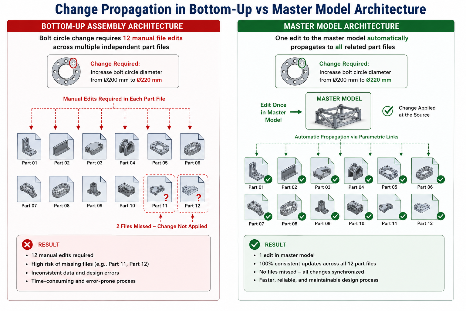
    The defining characteristic of parametric CAD is that changing a parameter value automatically propagates through the entire model, updating all dependent features according to the design intent encoded when the model was built. A parametric model of a bolt pattern does not just record where the holes are , it records that the holes are equally spaced around a bolt circle of a specified diameter, so changing the bolt circle diameter automatically repositions all holes correctly.

    Parametric vs Non-Parametric CAD

    AspectParametric CADNon-Parametric (Direct) CAD
    Change propagationChanges to parameters automatically update entire modelChanges apply only to the selected geometry; no automatic propagation
    Design intent storageDesign intent encoded in feature tree and constraintsGeometry only , no stored design intent
    Edit flexibilityStructured: edits must respect feature dependenciesFlexible: any face or edge can be moved freely
    Best forProduction design, repeated design iterations, family-of-parts designConcept modelling, imported geometry repair, quick shape exploration
    Learning curveSteeper: must plan feature structure to edit reliablyFaster to start: no upfront structural planning required
    Major toolsSolidWorks, CATIA, NX, Creo, InventorSpaceClaim, Fusion 360 (direct), Creo Flexible Modelling Extension

    Type 4: Direct Modelling (Explicit) CAD

    Direct modelling (also called explicit modelling or history-free modelling) is an approach where the engineer manipulates geometry directly , pushing faces, pulling edges, blending surfaces , without a parametric feature history constraining those manipulations. Each edit acts on the current state of the geometry rather than on a record of how it was built.

    Direct modelling has two primary use cases: fast concept exploration (where the freedom to modify without feature history constraints accelerates early-stage design) and working with imported geometry (where files from other CAD systems arrive as dumb solids without feature history). Tools like Ansys SpaceClaim (now SpaceClaim Engineer) are specifically optimised for the latter , preparing imported CAD geometry for FEA simulation by simplifying, repairing, and modifying solids that have no parametric history.

    Type 5: Surface Modelling CAD

    Surface modelling creates 3D shapes as collections of mathematical surfaces rather than as volumetric solids. Where solid modelling is analogous to sculpting a clay block, surface modelling is analogous to bending and joining sheets of material , building the outer skin of an object face by face.

    Surface modelling is essential for any design where the precise shape and curvature of the exterior surface is itself the primary design criterion: automotive body panels (where surface curvature affects aerodynamics, water runoff, and visual reflection quality), aircraft fuselage and wing skins (where aerodynamic performance is surface-quality dependent), and premium consumer product casings (where the visual and tactile quality of the surface is a primary differentiator).

    NURBS: The Mathematics of CAD Surfaces

    Most CAD surface modelling is based on NURBS (Non-Uniform Rational B-Splines) , a mathematical representation that can define smooth curves and surfaces of arbitrary complexity with a compact set of control points and weights. NURBS surfaces can represent everything from a perfect cylinder to a complex organic aerodynamic shape, and they export to neutral formats (IGES, STEP) without losing surface quality.

    Class A Surfaces

    The highest standard of surface quality in automotive and consumer product design is called Class A surfaces: surfaces that are not just smooth but have mathematically perfect curvature continuity across all joins. Class A is the standard for automotive exterior body panels and is tested by analysing how light and environment reflections behave across the surface , any discontinuity in curvature shows up as a visible distortion in the reflection. CATIA FreeStyle and Autodesk Alias are the primary tools for Class A surface creation.

    Type 6: Building Information Modelling (BIM) Software

    BIM software represents the application of CAD technology to the architecture, engineering, and construction (AEC) industry, with a fundamental difference from conventional CAD: in BIM, the model is not just a collection of geometric shapes but a database of intelligent building objects , walls, doors, windows, beams, pipes, ducts , each containing geometric, physical, and functional data about the real building element it represents.

    A BIM model of a building knows that the object labelled ‘Wall Type A’ is a 200mm thick load-bearing concrete wall with specific thermal properties, fire rating, and finish specifications. When a door is placed in that wall, the BIM software automatically creates the opening in the wall geometry, adjusts the wall area calculations, and records that the wall has a door of a specific type. This intelligence enables automatic generation of schedules, quantity takeoffs, energy analyses, and clash detection reports from a single coordinated model.

    BIM Levels of Development

    BIM LevelWhat It MeansKey Capability Enabled
    LOD 100 (Conceptual)Approximate size, shape, location, and orientationSite planning, massing studies, conceptual energy analysis
    LOD 200 (Schematic)Approximate geometry with generic object types, quantities, and systemsPreliminary clash detection, approximate cost estimating, coordination between disciplines
    LOD 300 (Design Development)Specific geometry, size, shape, location, orientation with real object typesDetailed clash detection, accurate quantity takeoff, construction coordination, permit drawings
    LOD 350 (Construction)Full construction detail with interface information for adjacent elementsComplete construction coordination, fabrication drawings, MEP coordination
    LOD 400 (Fabrication)Full fabrication and assembly detail , as-built representationOff-site fabrication, assembly sequencing, shop drawings
    LOD 500 (As-Built)Model verified on-site to actual conditionsFacilities management, maintenance planning, digital twin

    The dominant BIM software tool globally is Autodesk Revit, which holds approximately 60 to 70 percent of the BIM market for architectural and structural design. Graphisoft ArchiCAD is a strong competitor, particularly in Europe. Bentley’s OpenBuildings Designer is used for large infrastructure projects. The open exchange format for BIM data is IFC (Industry Foundation Classes), developed by buildingSMART International, which allows different BIM tools to exchange building model data without proprietary format dependency.

    Type 7: CAD/CAM Software , Design to Manufacture

    CAD/CAM software (Computer-Aided Design / Computer-Aided Manufacturing) combines 3D design tools with manufacturing programming tools in a single integrated workflow. The “manufacturing” part (CAM) generates the machine instructions , typically CNC toolpaths and G-code , needed to produce the designed component on a CNC milling machine, lathe, router, plasma cutter, or other computer-controlled manufacturing equipment.

    The fundamental advantage of an integrated CAD/CAM workflow is that the same geometric model used for design is used directly for manufacturing programming , there is no need to recreate or import geometry into a separate CAM package. Any change to the design model automatically updates the associated toolpaths when the CAM program is regenerated, reducing the risk of manufacturing from outdated geometry.

    What CAM Software Does

    • Toolpath generation: Calculates the precise path the cutting tool must follow to remove material from a workpiece and produce the designed geometry
    • Machine simulation: Simulates the complete cutting process to verify toolpaths, check for collisions between the tool/holder and workpiece/fixture, and estimate machining time
    • G-code output: Generates the machine-specific numerical control code (G-code) that is loaded into the CNC machine controller
    • Setup documentation: Produces setup sheets describing workholding, tool selection, cutting parameters, and operation sequence for the machinist

    The most significant CAD/CAM development for everyday engineers in recent years is Autodesk Fusion 360’s integrated CAD+CAM workflow. Fusion 360 provides fully capable 2.5-axis, 3-axis, 4-axis, and 5-axis milling, turning, and wire EDM programming alongside its 3D design tools in a single subscription at a price accessible to small manufacturers and individual engineers.

    Type 8: CAD/CAE Software , Simulation and Analysis

    CAD/CAE software (Computer-Aided Engineering) uses the geometry of a CAD model as the input for numerical simulation , predicting how a design will perform under real-world conditions before any physical prototype is built. The economic and safety value of this capability is enormous: finding that a bracket will fail under load in a simulation takes minutes and costs nothing to fix; finding it in a physical test takes weeks and may require costly tooling changes; finding it in service may cost lives.

    The Primary Types of CAE Simulation

    • Finite Element Analysis (FEA): Predicts structural stress, strain, deflection, and failure in solid components under mechanical, thermal, or dynamic loading. The most widely used simulation type in mechanical engineering.
    • Computational Fluid Dynamics (CFD): Simulates fluid flow (liquid or gas) around or through a 3D geometry , predicting aerodynamic drag, lift, pressure drops, heat transfer, and flow distributions.
    • Thermal analysis: Predicts temperature distributions through conduction, convection, and radiation , critical for electronics cooling, engine thermal management, and HVAC system design.
    • Modal analysis / dynamics: Predicts natural frequencies and vibration mode shapes of structures , essential for avoiding resonance failures.
    • Multi-physics simulation: Couples multiple physics domains (structural + thermal + fluid) in a single simulation , used for complex coupled problems like thermal expansion causing structural stress.

    The dominant CAE platform globally is ANSYS, which provides FEA, CFD, thermal, electromagnetic, and multi-physics simulation tools. SolidWorks Simulation provides integrated FEA within the SolidWorks environment. COMSOL Multiphysics specialises in coupled multi-physics problems. Autodesk Nastran and MSC Nastran are the aerospace and automotive standard for structural analysis.

    The Three Modelling Paradigms: Solid, Surface, and Mesh

    Within 3D CAD, three distinct mathematical paradigms are used to represent geometry. Understanding them explains why different CAD tools are used for different types of design work.

    ParadigmHow Geometry Is RepresentedBest ForStrengthsLimitations
    Solid Modelling (B-rep)Closed volumetric solids defined by bounding surfaces, edges, and verticesMechanical engineering, product design, structural components, anything that will be manufacturedMathematically complete, mass properties calculable, Boolean operations, FEA-readyLess suited to organic/sculptural shapes; requires watertight geometry
    Surface Modelling (NURBS)Collections of smooth mathematical surfaces without enclosing a volumeAutomotive styling, aerospace aerodynamics, consumer product aesthetics, complex curved shapesPerfect curvature control, Class A surfaces achievable, handles organic shapes wellSurfaces must be manually stitched and made watertight for manufacturing
    Mesh / Polygon ModellingGeometry approximated by a mesh of flat polygonal faces (triangles or quads)Game assets, visual rendering, 3D printing of organic shapes, reverse engineering from scan dataHandles highly complex organic shapes, fast for visualisation, compatible with 3D printingNot dimensionally precise, limited manufacturing suitability, large file sizes for complex models

    Modern professional CAD tools are increasingly hybrid, supporting multiple modelling paradigms within the same environment. SolidWorks supports both solid and surface modelling. CATIA and NX support all three. Fusion 360 integrates solid, surface, and mesh (T-spline) modelling. The ability to move fluidly between paradigms , starting with surface forms, solidifying them for structural analysis, and exporting mesh for visualisation , is increasingly a defining capability of enterprise-class CAD platforms.

    How CAD Fits into the Product Development Workflow

    CAD software does not exist in isolation. It sits within a structured product development or construction workflow that defines how design intent is captured, developed, verified, documented, and communicated from initial concept through to finished product or built structure. Understanding where each type of CAD fits in this workflow clarifies why different tools are used at different stages.

    Product development workflow diagram showing how CAD software types are used at each stage from concept design through 3D modelling FEA simulation and CNC manufacturing to 2D documentation
    Workflow StagePrimary ActivityCAD Type UsedTypical ToolsOutput
    Concept and IdeationSketching, form exploration, initial proportioningDirect modelling, sketch tools, mesh modellingFusion 360, SketchUp, Shapr3D, BlenderConcept sketches, rough 3D form studies
    Schematic DesignEstablishing spatial layout, system routing, design intent2D CAD, BIM, schematic toolsAutoCAD, Revit (BIM), Visio (schematics)Schematic drawings, layout plans, system diagrams
    Detail DesignFully detailed 3D models with all geometry, tolerances, and materialsParametric 3D CAD, surface CAD (for Class A)SolidWorks, CATIA, NX, Creo3D solid models, assembly models
    Analysis and SimulationVerifying structural integrity, fluid performance, thermal behaviourCAE simulation softwareANSYS, SolidWorks Simulation, COMSOL, FluentFEA stress results, CFD flow fields, factor of safety reports
    Manufacturing DocumentationCreating drawings, specifications, BOM, NC programs2D CAD, CAD/CAMAutoCAD, SolidWorks Drawing, Fusion 360 CAMEngineering drawings, bills of materials, CNC toolpaths, G-code
    Fabrication and ConstructionProducing the physical object or structure2D drawings, CAM G-code, BIM modelsFactory equipment, CNC machines, construction sitePhysical product or built structure
    Operations and MaintenanceManaging the built asset throughout its service lifeDigital twin, BIM (facilities), PLMBentley AssetWise, IBM Maximo, Autodesk TandemAs-built models, maintenance records, performance data

    CAD File Formats Explained

    CAD file formats are one of the most practically important topics for working engineers and designers. The choice of file format for exchanging CAD data between tools, teams, and organisations determines what information is preserved, what is lost, and what compatibility problems will arise.

    FormatTypeWhat It PreservesBest Used ForLimitations
    DWGNative (Autodesk)Full 2D drawing content: all AutoCAD objects, layers, styles, blocks, attributesSharing between AutoCAD users; universal 2D drawing exchangeProprietary format with version compatibility issues across AutoCAD versions
    DXFOpen interchange2D geometry, layers, blocks , simplified vs DWGSending 2D drawings to non-AutoCAD tools, CNC machines, laser cuttersComplex AutoCAD objects simplified or lost; older versions lose newer features
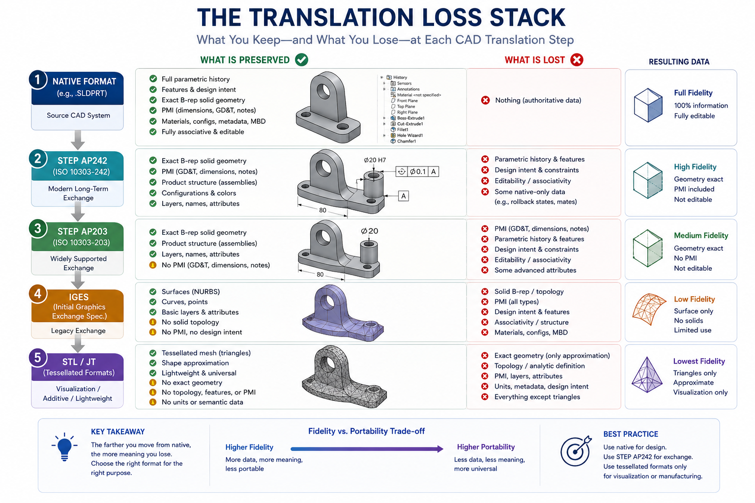
    STEP (.stp/.step)Open 3D neutralFull solid geometry, B-rep, assembly structure, some metadataGold standard for 3D solid model exchange between different CAD toolsDoes not preserve parametric history or feature trees
    IGES (.igs/.iges)Open 3D neutral (older)Surfaces, solids (B-rep), some assembly dataLegacy 3D exchange, particularly for surface-heavy aerospace/automotive dataOlder standard; STEP is generally preferred for new work
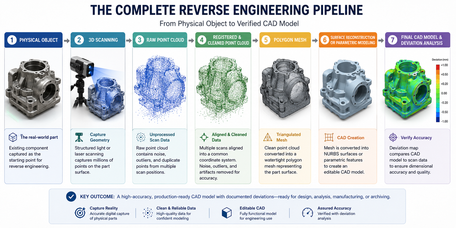
    STL3D printing / meshTriangle mesh approximation of 3D surface , no solid data3D printing, rapid prototyping, reverse engineering, visualisationNo exact geometry (faceted approximation), no parametric data, no units
    SLDPRT / SLDASMNative (SolidWorks)Full parametric feature history, assembly structure, matesWorking within SolidWorks environment; sharing with other SolidWorks usersOnly readable in SolidWorks (or with SolidWorks viewer)
    IFCOpen BIMFull BIM model: building objects, geometry, metadata, relationships, schedulesExchanging BIM models between Revit, ArchiCAD, and other BIM toolsNot all tools implement IFC equally; some data loss common across platforms
    FBXVisualisation / animationMesh geometry, materials, textures, animation data3D rendering, visualisation, game engine importNot suitable for engineering manufacturing
    Parasolid (.x_t)Geometric kernel neutralFull B-rep solid geometry without feature historyTransferring solid geometry between tools sharing Parasolid kernelLimited tool support compared to STEP
    OBJMesh / visualisationPolygon mesh, materials, texture coordinates3D visualisation, rendering, web 3D, game assetsNo engineering precision, no solid data, no dimensions
    File Format Decision Rule:  For 3D solid model exchange between different CAD tools: use STEP (.step). It is the most universally supported neutral 3D format and preserves solid geometry with the least data loss. For 2D drawing exchange with non-AutoCAD users or fabrication services: use DXF (R14). For 3D printing: use STL. For BIM model exchange: use IFC. Always keep your native format (.sldprt, .dwg, .rvt) as the master file.

    Desktop CAD vs Cloud-Native CAD: Architecture and Trade-offs

    The fundamental architecture of CAD software , whether it runs on a local workstation or lives in the cloud , is one of the most consequential decisions in modern CAD adoption. This is not just a technical question. It affects security, collaboration, hardware cost, IT overhead, and the long-term direction of the engineering workflow.

    DimensionDesktop CADCloud-Native CAD
    Data locationLocal hard drive or company serverVendor cloud (AWS, Google, Azure infrastructure)
    ProcessingLocal CPU/GPU , performance limited by workstation specHybrid: geometry solving local, storage and collaboration cloud
    CollaborationPDM/PLM required (Vault, Teamcenter, Windchill)Built-in real-time collaboration without PDM infrastructure
    Version controlManual (naming conventions) or PDM-managedAutomatic, branching/merging model similar to git
    Offline workingFull functionalityReduced , most operations require internet
    Hardware costHigh-spec workstation required ($2,000-$8,000+)Any modern computer with web browser
    IT overheadSignificant , installs, updates, licence servers, PDM adminMinimal , vendor manages infrastructure
    Data security / IPData under company controlData on vendor infrastructure , IP risk consideration
    Large assembly performanceBetter , local processing not network-limitedLimited , large assemblies can be slow over network
    Feature maturityMost mature , decades of developmentImproving rapidly , some gaps vs desktop at extremes
    Best forEnterprise engineering, large assemblies, aerospace, automotive, any IP-sensitive sectorStartups, SMEs, remote teams, hardware companies, rapid product development

    The CAD Software Ecosystem: Point Tools vs Integrated Suites

    The CAD software ecosystem is structured into three distinct categories that reflect different approaches to the relationship between design, simulation, manufacturing, and data management:

    Point Tools

    Point tools are software applications designed to do one thing exceptionally well. AutoCAD is a point tool for 2D drafting. ANSYS Fluent is a point tool for CFD. Mastercam is a point tool for CAM. Point tools offer the deepest capability in their specific domain and are often the preferred choice of specialists, but they require file translation workflows when moving data between stages of the development process.

    Integrated Suites

    Integrated suites combine multiple CAD, simulation, and data management capabilities within a single platform and data model. Siemens NX integrates CAD, CAM, and CAE. Autodesk Fusion 360 integrates CAD, CAM, and simulation. Dassault 3DEXPERIENCE integrates SolidWorks/CATIA, simulation, and PLM. Integrated suites eliminate file translation between stages and ensure that the analysis model is always in sync with the design model, at the cost of less depth in any individual domain compared to the best specialist point tools.

    Platform Ecosystems

    The largest CAD vendors have evolved from selling software tools to building platform ecosystems that connect CAD tools with PDM, PLM, ERP, simulation, generative design, IoT, and digital twin technologies. Autodesk’s Platform Services (formerly Forge) and Construction Cloud, Dassault’s 3DEXPERIENCE Marketplace, Siemens’ Xcelerator portfolio, and PTC’s ThingWorx IoT + Windchill PLM all represent attempts to expand the value of CAD from a design tool into the connective tissue of the entire product lifecycle.

    Best CAD Software by Engineering and Design Discipline

    DisciplinePrimary CAD ToolAlternative / Specialist ToolKey Reason
    Mechanical Engineering (Product Design)SolidWorksAutodesk Inventor or Fusion 360Dominant market share, largest ecosystem, most employer-required parametric 3D tool in mid-market
    Mechanical Engineering (Enterprise/Aerospace)CATIA or Siemens NXPTC CreoMandated by major aerospace and automotive OEMs; only tools with the scale for complex programs
    Civil EngineeringAutoCAD Civil 3DBentley MicroStation / OpenRoadsDominant for road, drainage, and site design; Bentley for large infrastructure networks
    Architecture (Documentation)AutoCADMicroDraft, VectorWorksUniversal standard for architectural technical drawings and construction documentation
    Architecture (BIM)Autodesk RevitGraphisoft ArchiCADMarket-leading BIM platform for architectural design and multi-discipline coordination
    Structural EngineeringAutoCADTekla Structures (structural steel)AutoCAD for detailing; Tekla for 3D structural steel fabrication modelling
    Electrical EngineeringAutoCAD ElectricalEPLAN (EDA, not traditional CAD)AutoCAD Electrical toolset for wiring diagrams; EPLAN for complex panel design
    Manufacturing / CNCFusion 360 (CAD+CAM)Mastercam, NX CAMFusion 360’s integrated CAD+CAM at competitive price; Mastercam for advanced multi-axis
    Product Design / Industrial DesignFusion 360 or Rhino 3DSolidWorks, Alias (styling)Fusion 360 for functional design; Rhino for complex form; Alias for automotive Class A styling
    3D Printing / AdditiveFusion 360 or nTopSolidWorks, FreeCADFusion 360 has best generative/lattice design for AM; nTop (nTopology) for advanced lattice structures

    AI and the Future of CAD Software

    Artificial intelligence is beginning to transform CAD software at a pace that is accelerating in 2024 and 2026. The changes range from incremental productivity improvements to potentially fundamental shifts in how engineering design is done.

    Generative Design

    Generative design uses AI optimisation algorithms to explore thousands of design configurations based on engineering constraints defined by the engineer: load cases, material constraints, manufacturing method, mass targets, and performance objectives. The resulting geometries are often organic in form , mathematically optimised rather than intuitively designed , and frequently achieve the same structural performance as conventional designs at 20 to 50 percent lower mass.

    Autodesk’s generative design tools (in Fusion 360 and Inventor) are the most widely deployed. nTop (nTopology) specialises in lattice and field-driven generative structures for additive manufacturing. SOLIDWORKS AI Topology Study provides topology optimisation within the SolidWorks environment.

    AI-Assisted Design Workflows

    • SOLIDWORKS Aura (2026): An AI co-pilot embedded in SolidWorks that answers design questions, suggests features, and assists with model creation through conversational interaction.
    • Autodesk AI (Fusion 360 / AutoCAD): AI-powered command autocomplete, design suggestions, and automated drawing creation features being rolled out across Autodesk products.
    • Physics-Informed Neural Networks (PINNs): Research-stage AI that can solve FEA and CFD problems at speeds orders of magnitude faster than traditional solvers, enabling real-time simulation during design.
    • Automated drawing creation: AI tools that automatically generate 2D drawing views, add dimensions, and create title blocks from 3D models, reducing documentation time significantly.

    The Long-Term Trajectory

    The convergence of AI, generative design, and digital twin technology is moving CAD software toward a future where the engineer’s role shifts from geometry creation toward design intent specification: defining the problem (loads, materials, constraints, cost targets) and evaluating the AI-generated solutions rather than manually creating every geometric feature. This is not imminent for most engineering work , the complexity and safety criticality of most engineered products ensures that human engineering judgement will remain central for decades. But the direction of travel is clear and the pace is accelerating.

    CAD Software Career Paths and Certifications

    Proficiency in CAD software is not a career in itself , it is a foundational skill that amplifies the value of engineering, architecture, and design expertise. The career paths built on CAD proficiency span roles from CAD technician through to engineering director, and the salary premium for certified CAD proficiency is consistently documented across all major engineering job markets.

    Career PathPrimary CAD ToolsKey CertificationsTypical Entry Salary (US)Senior Potential
    Mechanical Design EngineerSolidWorks or NX/CATIACSWP, CSWE (SolidWorks)$65,000-$80,000$110,000-$150,000+
    Civil/Infrastructure EngineerAutoCAD Civil 3D, MicroStationAutodesk ACP Civil 3D$60,000-$75,000$95,000-$130,000
    Structural EngineerAutoCAD, Tekla, RevitAutodesk ACP, Tekla certification$60,000-$72,000$90,000-$125,000
    Architectural DesignerAutoCAD, RevitAutodesk ACP AutoCAD/Revit$55,000-$70,000$85,000-$120,000
    Manufacturing/CNC EngineerFusion 360, Mastercam, NXAutodesk CAM certification$60,000-$75,000$90,000-$120,000
    CAE/Simulation EngineerANSYS, SolidWorks Simulation, AbaqusANSYS certification programmes$70,000-$90,000$115,000-$155,000
    BIM Manager / CoordinatorRevit, Navisworks, Civil 3DAutodesk Certified Professional (Revit)$65,000-$80,000$95,000-$130,000
    Aerospace Structural EngineerCATIA, NX, ANSYS NastranCATIA/NX certificates, PE licence$80,000-$100,000$130,000-$180,000+
    Certification Strategy:  The highest-return CAD certification investment for most engineers in 2026 is the SOLIDWORKS Certified Professional (CSWP) , independently validated, widely recognised by employers, and consistently associated with 15 to 25 percent salary premiums. For multi-discipline engineers, the Autodesk Certified Professional (ACP) in AutoCAD provides the broadest career coverage. Both can be achieved through self-study and tested at Autodesk/Dassault-authorised testing centres globally.

    Frequently Asked Questions (FAQ)

    What is CAD software?

    CAD software (Computer-Aided Design software) is a category of computer application used to create, modify, analyse, and document designs of physical objects, structures, and systems with engineering-level precision. It ranges from 2D technical drafting programs (AutoCAD) to 3D parametric solid modelling tools (SolidWorks, CATIA), architectural BIM platforms (Revit), simulation software (ANSYS), and integrated CAD/CAM manufacturing programming systems (Fusion 360). CAD software replaced manual drawing boards across engineering, architecture, and manufacturing, and is used by over 10 million professional engineers, architects, and designers globally.

    What are the main types of CAD software?

    The eight main types of CAD software are: (1) 2D CAD for technical drawing and documentation (AutoCAD); (2) 3D Solid Modelling CAD for creating volumetric product models (SolidWorks, Inventor); (3) Parametric CAD for intelligent models that update by design intent (SolidWorks, CATIA, NX); (4) Direct Modelling CAD for flexible geometry manipulation without history (SpaceClaim); (5) Surface Modelling CAD for complex curved forms (CATIA FreeStyle, Rhino, Alias); (6) BIM software for intelligent building design (Revit, ArchiCAD); (7) CAD/CAM software for design-to-manufacture (Fusion 360, Mastercam); (8) CAE/Simulation software for design analysis (ANSYS, SolidWorks Simulation).

    What is parametric CAD?

    Parametric CAD is a 3D CAD approach where the model captures design intent , the relationships, constraints, and governing dimensions that define how the design is meant to work , alongside the geometry. When a parameter is changed (for example, a dimension or a constraint), the entire model updates automatically to reflect the change throughout all dependent features. Parametric CAD tools include SolidWorks, CATIA, Siemens NX, PTC Creo, and Autodesk Inventor. It contrasts with direct modelling, where geometry is manipulated freely without stored parametric history.

    What is BIM and how is it different from CAD?

    BIM (Building Information Modelling) is a specific type of CAD for the construction industry where the model contains not just geometry but intelligent building objects , walls, doors, beams, pipes , each containing physical, functional, and material data about the real building element they represent. Unlike standard CAD (which produces geometric shapes), BIM models automatically generate schedules, cost estimates, energy analyses, and clash detection reports because the objects are data-rich. The most widely used BIM tool is Autodesk Revit. BIM is a form of CAD, but with intelligence, data, and multi-discipline coordination capabilities that standard CAD tools do not provide.

    What is the difference between CAD, CAM, and CAE?

    CAD (Computer-Aided Design) creates the 3D model or 2D drawing of the product or structure. CAM (Computer-Aided Manufacturing) uses the CAD model to generate the machine instructions (CNC toolpaths, G-code) needed to manufacture the part on computer-controlled equipment. CAE (Computer-Aided Engineering) uses the CAD model as input for numerical simulation (FEA, CFD, thermal analysis) to verify that the design will perform as required before physical testing. These three disciplines represent the progression from design through analysis to manufacture, and modern integrated tools like Fusion 360 and NX combine all three in a single platform.

    What is the best CAD file format for sharing with other software?

    The best CAD file format for sharing 3D solid models between different CAD tools is STEP (.step or .stp) , it is an open, internationally standardised format that preserves complete B-rep solid geometry and assembly structure with minimal data loss across all major CAD platforms. For 2D drawing exchange, DXF (R14) is the most widely compatible format, readable by virtually every CAD tool and fabrication system. For 3D printing, use STL. For BIM model exchange, use IFC. Always retain your native format file as the master document.

    What CAD software is best for beginners?

    The best CAD software for beginners depends on the target discipline. For general engineering and the widest career applicability: AutoCAD (free student licence) for 2D drafting and Fusion 360 (free for students/personal use) for 3D modelling are the most accessible starting points. Both have large communities, abundant tutorials, and free access for learners. For those targeting architecture, Revit’s student version is the appropriate starting tool. For mechanical engineering specifically, SolidWorks student licences provide access to the industry’s most widely used professional tool at low cost.

    How is AI changing CAD software?

    AI is changing CAD software in several important ways in 2026: Generative design algorithms explore thousands of design configurations based on constraints, producing optimised geometries at lower mass; AI co-pilots (SolidWorks Aura, Autodesk AI) embed conversational AI assistance directly into the design workflow; Physics-Informed Neural Networks are beginning to accelerate FEA and CFD simulation by orders of magnitude; and automated drawing creation tools are reducing documentation time. The long-term trajectory moves the engineer’s role from geometry creation toward design intent specification and AI-generated solution evaluation.

    What is the difference between 2D CAD and 3D CAD?

    2D CAD produces flat technical drawings on a 2D plane , engineering drawings, floor plans, schematics , that describe an object’s shape through multiple views (front, top, side) and dimensions. It is the direct digital replacement for the drawing board. 3D CAD creates a complete three-dimensional digital model of an object in a 3D coordinate space. The 3D model has volume, mass, and surface area, can be viewed from any angle, can be used for simulation and interference checking, and can automatically generate 2D drawing views. Most modern engineering workflows use 3D CAD for design and 2D CAD drawings for manufacturing documentation.

    What is NURBS in CAD?

    NURBS (Non-Uniform Rational B-Splines) is the mathematical representation used by most professional CAD tools to define smooth curves and surfaces. NURBS surfaces can describe anything from a simple flat plane to a complex aerodynamic fuselage shape with perfect mathematical continuity. They are defined by control points and weights that determine how the surface is pulled toward each control point. NURBS is the standard representation for surface modelling in tools like CATIA, Rhino, Autodesk Alias, and SolidWorks. The STEP and IGES file formats preserve NURBS surface data for exchange between tools.

    Conclusion

    CAD software is not a single technology. It is a diverse family of tools, each evolved to address a specific aspect of the design, analysis, documentation, and manufacturing workflow. Understanding the landscape , what each type of CAD is for, how the types relate to each other, how the major tools within each type compare, and how the whole ecosystem fits together , is the foundation for making intelligent decisions about which tools to learn, which to deploy, and which to commission.

    The history of CAD is a history of progressive democratisation: from room-sized mainframes accessible only to the largest aerospace corporations in the 1960s, to personal computer tools accessible to any engineering firm by the 1990s, to cloud-native tools accessible to any individual engineer for free today. Each wave of democratisation has expanded the population of people who design and engineer things, and the current wave, AI-assisted generative design and cloud collaboration, will continue that expansion.

    For students and early-career engineers, the practical implication is clear: invest in genuine proficiency in the tools that matter for your industry (not the tools with the best marketing), obtain recognised certifications where available, and stay alert to the AI-driven changes that are beginning to reshape what CAD proficiency means in practice. The engineer who can specify design intent, evaluate AI-generated solutions, and communicate effectively with manufacturing and construction teams , amplified by deep CAD toolset knowledge, will be the most valuable engineering professional of the next decade.

    Explore the full CAD Software cluster: Best CAD Software for Engineers , our comprehensive tool-by-tool comparison with pricing, industry fit, and career impact. Or begin building your foundational CAD skills with AutoCAD Tutorials for Beginners and Professionals.

  • Dynamic Block Lookup Tables in AutoCAD Explained (2026)

    Dynamic Block Lookup Tables in AutoCAD Explained (2026)

    AutoCAD’s dynamic blocks are one of the most powerful productivity tools in the software, allowing a single block definition to represent dozens or even hundreds of variations through parameters and actions. But even among experienced AutoCAD users who are comfortable with stretch, scale, and visibility parameters, lookup tables remain one of the least understood and most underused features of the dynamic block system.

    A lookup table takes a dynamic block to a completely different level of usability. Instead of users having to manipulate grips, type specific values, or know the exact dimensions of a component they are placing, a lookup table presents them with a simple dropdown list: select ‘M8 Bolt’, or ‘Type A Door’, or ‘600mm Wide Desk’, and the block automatically sets all associated parameters to the correct values simultaneously. One selection drives everything.

    This guide explains AutoCAD dynamic block lookup tables from the ground up. It covers what they are and why they are useful, the conceptual building blocks (lookup parameters versus lookup actions), how to create a single-parameter lookup table step by step, how to build a multi-parameter lookup that drives multiple block properties from one dropdown, the Allow Reverse Lookup setting that confuses almost every user who first encounters it, how to extract lookup data for bills of materials and parts lists, and a full troubleshooting reference for every common problem.

    Quick Answer:  A dynamic block lookup table in AutoCAD is a table inside a dynamic block definition that maps a named entry (e.g. ‘M10 Bolt x 50mm’) to a specific set of parameter values (e.g. Diameter = 10, Length = 50, Head Height = 6.4). When a user selects that entry from the block’s grip dropdown, AutoCAD automatically applies all associated parameter values simultaneously. It is created in the Block Editor using a Lookup Parameter and a Lookup Action.

    What Is a Dynamic Block Lookup Table and Why Use One?

    In the context of AutoCAD dynamic blocks, a lookup table is a structured internal table that associates named text entries (the list items a user sees in the dropdown) with corresponding values for one or more block parameters. It is the mechanism that converts a block from something a user manipulates by dragging grips to something a user selects from a predefined list.

    Think of a lookup table as the dynamic block equivalent of a product catalogue. A block representing a structural steel section might have a lookup table containing every standard section size: UC203x203x60, UC203x203x71, UC254x254x89, and so on. The user selects the section from the dropdown, and the block instantly updates to the correct flange width, depth, and web thickness , all values set simultaneously from a single selection.

    The Problem Lookup Tables Solve

    Without a lookup table, a dynamic block user faces one of two sub-optimal workflows. Either they drag grips and hope they snap to the correct values, or they type exact values into the Properties palette manually. Both approaches are slow and error-prone, especially when blocks represent components with manufacturer-standard dimensions that must be exact.

    A lookup table eliminates both problems. It constrains the block to only valid, predefined configurations and presents those configurations in a human-readable named list. The user never needs to know the exact numeric values , they just pick the configuration they need.

    Read related article on How to Sort Tables in AutoCAD

    When to Use a Lookup Table vs Other Dynamic Block Features

    SituationBest ApproachWhy
    Block has 2-3 continuous size variations that users need to set to any valueLinear/scale parameter with value sets or incrementLookup table adds unnecessary complexity for simple continuous size changes
    Block has a fixed catalogue of named configurations (e.g. standard hardware, furniture sizes)Lookup tableBest: presents named options, ensures only valid configurations are used, drives multiple parameters at once
    Block needs to show/hide different geometry based on a selectionVisibility statesVisibility states are specifically designed for geometry show/hide. Lookup tables control parameter values, not direct visibility.
    Block has named configurations AND geometry differences (e.g. door type with different swing geometry)Lookup table + Visibility states combinedUse lookup for dimensions, visibility states for geometry changes, link them via the lookup table
    Block configuration depends on 3+ parameters that all change togetherLookup table with multiple property columnsOnly a lookup table can drive multiple parameters simultaneously from one selection

    Lookup Parameter vs Lookup Action: Understanding the Two-Part System

    The single most common source of confusion for users learning dynamic block lookup tables is not understanding the relationship between the Lookup Parameter and the Lookup Action. These are two separate objects placed in the Block Editor, and both are required. Neither works without the other. Understanding what each one does makes the entire workflow logical.

    ObjectWhat It IsWhat It DoesVisible to User?
    Lookup ParameterA parameter added from the Parameters tab of the Block Authoring PaletteProvides the grip (dropdown handle) that users see and interact with when the block is inserted. It holds the currently selected lookup value name (e.g. ‘M10 Bolt x 50mm’). The parameter itself has no values until connected to a Lookup Action.Yes , the grip appears as a small arrow or diamond on the inserted block
    Lookup ActionAn action added from the Actions tab of the Block Authoring PaletteContains the actual lookup table: the rows of data mapping named entries to parameter values. The Lookup Action reads the current value of the Lookup Parameter and sets all other block parameters to the corresponding row values in its table.No , the action is invisible in the drawing. It is a background engine.

    The workflow is therefore always in this order: (1) Set up the block parameters that will be controlled by the lookup table (length, width, visibility state, etc.). (2) Place the Lookup Parameter in the Block Editor. (3) Place the Lookup Action and attach it to the Lookup Parameter. (4) Open the Lookup Table inside the Lookup Action and populate the rows with named entries and corresponding parameter values.

    The Most Common Mistake:  Placing a Lookup Action without first setting up the parameters it will control. A Lookup Action is only useful if there are already named parameters in the block (linear parameters, visibility states, rotation parameters, etc.) whose values the action will set. If you open the Lookup Table and the ‘Add Properties’ button produces an empty list, it means no controllable parameters are available , go back and add the required parameters first.

    Prerequisites: What Your Dynamic Block Needs Before Adding a Lookup Table

    Before adding a lookup table, the dynamic block must already have the parameters whose values the lookup table will control. Here is what must be in place before entering the Block Editor to add lookup functionality:

    • At least one controlling parameter: A Linear parameter (for size), Rotation parameter (for angle), Visibility parameter (for geometry variants), or any other named parameter that can hold a value. The lookup table will set the values of these parameters.
    • Parameters must be named: Each parameter should have a clear, descriptive name (e.g. ‘Width’, ‘Height’, ‘Leg Style’) so you can identify it when adding columns to the lookup table.
    • For multi-parameter lookups: All parameters you want the lookup to control must be present in the block before adding the Lookup Action. You cannot add parameters to the lookup table that do not yet exist in the block.
    • The block should be tested without the lookup: Verify that the parameters and their associated actions (Stretch, Scale, Visibility) work correctly by testing the block with grip manipulation before adding the lookup layer on top.

    Step-by-Step: Creating a Single-Parameter Lookup Table

    This walkthrough creates a lookup table for a bolt block that already has a Linear parameter named ‘Length’ controlling the bolt body geometry via a Stretch action. The lookup table will let users select bolt lengths from a named list (M8x20, M8x25, M8x30, M8x40) rather than dragging a grip.

    Step 1: Open the Block Editor

    1. Double-click the inserted block to open it, or type BEDIT and press Enter, then select the block definition from the list.
    2. The Block Editor opens. The Block Authoring Palettes panel should be visible on the left. If not, go to Block Editor tab > Manage panel > Authoring Palettes to show it.

    Step 2: Place the Lookup Parameter

    1. In the Block Authoring Palettes, click the Parameters tab.
    2. Scroll down to find Lookup in the parameter list and click it.
    3. AutoCAD prompts: Specify parameter location:. Click a location on the block where the grip (dropdown handle) will appear when the block is inserted. A good position is just to the side of the block, away from functional grips.
    4. AutoCAD prompts for the number of grips: accept the default of 1 and press Enter.
    5. A Lookup grip appears at the specified location, labelled ‘Lookup’ by default. In the Properties palette (Ctrl + 1), rename the parameter to something descriptive, such as ‘Bolt Size’ or ‘Select Size’. This name appears as the label next to the grip when the block is in use.
    AutoCAD Block Editor showing Lookup Parameter being placed in the Block Authoring Palette for a bolt dynamic block lookup table

    Step 3: Place the Lookup Action

    1. In the Block Authoring Palettes, click the Actions tab.
    2. Click Lookup in the action list.
    3. AutoCAD prompts: Select parameter:. Click the Lookup Parameter you placed in Step 2 (the grip labelled ‘Bolt Size’).
    4. The Property Lookup Table dialogue opens automatically. This is the actual lookup table where you define the rows of data.

    Step 4: Build the Lookup Table

    1. In the Property Lookup Table dialogue, click Add Properties.
    2. A list of the block’s controllable parameters appears. Select ‘Length’ (the parameter you want to control). Click OK. A ‘Length’ column appears in the table.
    3. The table now has two columns: Lookup Name (the dropdown text the user will see) and Length (the parameter value AutoCAD will set).
    4. Click in the first empty row of the Lookup Name column and type the first entry name (e.g. ‘M8 x 20mm’). Press Tab to move to the Length column and type the corresponding value: 20.
    5. Press Enter or click the next row. Continue adding rows for each size:
    Lookup Name (User Sees)Length (Parameter Value)
    M8 x 20mm20
    M8 x 25mm25
    M8 x 30mm30
    M8 x 40mm40
    M8 x 50mm50
    1. In the Lookup name column at the bottom of the table (the last row with a dropdown), set the Input Properties setting to Allow Reverse Lookup. This setting is critical , see the next section for a full explanation.
    2. Click OK to close the Property Lookup Table dialogue.
    3. Go to Block Editor tab > Close panel > Save Block and then Close Block Editor.

    Step 5: Test the Lookup Table

    1. Insert or select the block in the drawing.
    2. Click the Lookup grip (the dropdown handle you placed). A dropdown list appears with the names you entered: M8 x 20mm, M8 x 25mm, M8 x 30mm, etc.
    3. Select any entry. The block’s Length parameter updates to the corresponding value and the block geometry stretches to match.
    Verification Step:  After testing, open the Properties palette (Ctrl + 1) with the block selected. The palette should show the Lookup Parameter name and its current value. Check that the Length parameter value matches the number you entered in the lookup table for the selected entry. If it does not match, revisit the Lookup Action and verify the correct parameter column is mapped to the correct value.
    AutoCAD dynamic block with lookup table dropdown showing named desk configurations including L-shape options available for selection

    More guide on How to Use DXF Files in AutoCAD

    Step-by-Step: Creating a Multi-Parameter Lookup Table

    The real power of AutoCAD dynamic block lookup tables becomes apparent when driving multiple parameters simultaneously from a single dropdown selection. This worked example creates a lookup table for a desk block with three parameters: Width (linear), Depth (linear), and Style (visibility state for standard vs L-shaped desk geometry).

    Block Setup Before Adding the Lookup

    This block already has:

    • Linear Parameter ‘Width’ , controlling the desk width with a Stretch action
    • Linear Parameter ‘Depth’ , controlling the desk depth with a Stretch action
    • Visibility Parameter ‘Desk Style’ , with two visibility states: ‘Standard’ (rectangular desk) and ‘L-Shape’ (L-shaped desk geometry)

    Adding the Multi-Parameter Lookup

    1. Open the Block Editor (BEDIT) for the desk block.
    2. Add a Lookup Parameter from the Parameters tab, placed at a convenient grip location. Name it ‘Select Desk’ in the Properties palette.
    3. Add a Lookup Action from the Actions tab, clicking the Lookup Parameter you just placed.
    4. The Property Lookup Table dialogue opens. Click Add Properties.
    5. Select Width, Depth, and Desk Style from the parameter list. All three are now columns in the table.
    6. Fill in the table with all required desk configurations:
    Lookup NameWidthDepthDesk Style
    600 x 600 Standard600600Standard
    800 x 600 Standard800600Standard
    1000 x 600 Standard1000600Standard
    1200 x 600 Standard1200600Standard
    1200 x 800 Standard1200800Standard
    1400 x 800 Standard1400800Standard
    1200 x 1200 L-Shape12001200L-Shape
    1400 x 1400 L-Shape14001400L-Shape
    1600 x 1600 L-Shape16001600L-Shape
    1. Set the Input Properties for the last table row to Allow Reverse Lookup.
    2. Click OK, save the block, and close the Block Editor.
    3. Test the block: clicking the ‘Select Desk’ grip should show a dropdown of all nine configurations. Selecting ‘1200 x 1200 L-Shape’ should simultaneously set Width to 1200, Depth to 1200, and switch the visibility state to L-Shape geometry.
    Multi-Parameter Power:  Notice that one selection from the dropdown drove three separate parameters at the same time. Without a lookup table, a user would need to set Width, Depth, and Desk Style separately , three operations instead of one. As the number of parameters and configurations grows, the time savings from a lookup table multiply significantly.

    Allow Reverse Lookup vs Read Only: The Most Misunderstood Setting

    The Input Properties setting at the bottom of the lookup table (the dropdown in the final row of the table) is one of the most confusing aspects of dynamic block lookup tables. Almost every user who first builds a lookup table wonders why it is not working , and the answer is almost always this setting.

    AutoCAD Property Lookup Table dialogue showing multi-parameter lookup table with Allow Reverse Lookup setting selected
    SettingWhat It DoesVisible in Dropdown?When to Use It
    Allow Reverse LookupAllows the lookup table to work in both directions: the user can select from the dropdown (lookup name → parameter values) AND AutoCAD can determine the current lookup name by reading the current parameter values. The dropdown list of named entries IS visible to the user.YES , user sees the named entries and can select from themAlmost always. This is the standard setting for any lookup table where users need to select from a dropdown list. If the lookup dropdown appears empty or shows no entries, this setting is almost certainly missing.
    Read OnlyThe lookup table only works in one direction: parameter values → lookup name. The current lookup name updates to reflect parameter values set by other means (grip manipulation), but the user CANNOT select from the dropdown , it is read-only. Named entries are NOT visible for selection.NO , no selectable entries in the dropdownOnly in rare specialist cases where the lookup name is used purely as a display label that tracks parameter values without allowing user selection. Not appropriate for standard dropdown-selection workflows.
    The Single Most Common Lookup Table Problem:  You build a lookup table, close the Block Editor, insert the block, click the grip, and the dropdown appears but shows no entries , or shows ‘Custom’ and nothing else. The cause is almost always Input Properties set to ‘Read Only’ instead of ‘Allow Reverse Lookup’. Open the Block Editor, double-click the Lookup Action, open the Property Lookup Table, and change the Input Properties dropdown at the bottom of the table from Read Only to Allow Reverse Lookup. Save and test. This fixes the problem in virtually every case.

    The Custom Entry: Why It Appears and What It Means

    When you insert a dynamic block with a lookup table and click the Lookup grip, you may see ‘Custom’ as an entry in the dropdown list, sometimes with a checkmark beside it. This confuses almost every user who encounters it for the first time.

    What ‘Custom’ Means

    ‘Custom’ is AutoCAD’s way of telling you that the block’s current parameter values do not match any named entry in the lookup table. It appears as a checkmarked entry when the block is in a state that falls outside the defined catalogue of configurations.

    This most commonly happens in three situations: when the block has just been inserted before any lookup selection has been made (the block is in its default state which may not match any lookup entry); when a user has manually set parameter values by dragging grips or typing in the Properties palette to a value not listed in the lookup table; or when the block has been copied from a version with different parameter defaults.

    Should You Worry About ‘Custom’?

    Not necessarily. ‘Custom’ is informational , it tells the user the block is currently in a non-catalogued state. To remove ‘Custom’ from the dropdown entirely: ensure that the block’s default parameter values (set in the Block Editor) match one of the entries in the lookup table. If the default Width is 800 and the lookup table has an ‘800 x 600 Standard’ entry with Width = 800, the block will start in that named state and ‘Custom’ will not appear.

    Real-World Use Cases for Dynamic Block Lookup Tables

    The following examples represent the most common and valuable applications of dynamic block lookup tables across engineering, architecture, and design disciplines.

    IndustryBlock ExampleLookup Table EntriesParameters Controlled
    Mechanical EngineeringStandard bolt or fastener blockM6x20, M6x25, M8x20, M8x25, M8x30, M10x30, M10x40…Shaft diameter, length, head height, thread length , all from one selection
    Mechanical EngineeringStructural steel section blockUC203x203x46, UC203x203x60, UC254x254x73, UB254x102x25…Section depth, flange width, web thickness, mass/metre label visibility
    ArchitectureDoor blockSingle 762, Single 838, Single 914, Double 1524, Double 1676…Door width, door height, single/double visibility state, swing direction
    ArchitectureWindow block600 Fixed, 900 Casement, 1200 Casement, 1800 Fixed…Opening width, frame depth, fixed/casement visibility state
    Electrical EngineeringElectrical cabinet / switchboard block200H x 400W, 400H x 400W, 600H x 600W, 800H x 600W…Overall height, overall width, number of circuit rows visibility
    Interior Design / FF&EOffice chair blockTask Chair, Executive Chair, Meeting Chair, Bar Stool…Seat height, back height, armrest visibility, star base/bar base visibility
    Civil EngineeringManhole block450 Dia, 600 Dia, 900 Dia, 1200 Dia, 1500 Dia…Chamber diameter, cover diameter, cover type visibility
    Manufacturing / WorkshopStandard channel section25x25x3, 40x40x5, 50x50x6, 75x50x6…Width, height, wall thickness , all simultaneously from standard size list

    Extracting Lookup Table Data for Bills of Materials and Parts Lists

    One of the most powerful and least-known capabilities of dynamic block lookup tables is that the lookup name value , the text that appears in the dropdown , can be extracted from the drawing as part of a Data Extraction, exactly like a block attribute. This allows a drawing containing multiple dynamic block instances to automatically generate a parts list, bill of materials, or schedule showing the lookup name for each block.

    How Lookup Data Appears in Data Extraction

    When you run DATAEXTRACTION on a drawing containing dynamic blocks with lookup tables, the lookup parameter name and its current value (the selected lookup name) appear in the property list on Page 3 of the wizard (Select Properties). Select the lookup parameter property to include it in the extraction, and the generated table will show the selected lookup entry for each block instance.

    Step-by-Step: Extracting Lookup Table Data

    1. Ensure all dynamic blocks in the drawing have their lookup selections set correctly.
    2. Type DATAEXTRACTION and press Enter.
    3. On Page 2 (Define Data Source), select Drawings/Sheet Set and check that the current drawing is included.
    4. On Page 3 (Select Objects), select the block definition you want to extract data from. Tick Display all object types if the block does not appear in the initial list.
    5. On Page 3 (Select Properties), scroll through the property list to find the Lookup Parameter name (e.g. ‘Bolt Size’, ‘Select Desk’). Tick it along with any other block properties or attributes you want in the extraction.
    6. Continue through the wizard, set up the output table format, and insert the extracted table. The resulting table shows each block instance with its selected lookup name.
    Practical Application:  A structural engineer places 47 instances of a steel section dynamic block throughout a drawing, selecting different section sizes from the lookup dropdown for each. Running DATAEXTRACTION generates a full steel schedule automatically , showing section designation, quantity, and total length for each section size. Updating any block’s selection and refreshing the Data Extraction table updates the schedule instantly.

    Editing and Updating an Existing Lookup Table

    Adding new entries, changing values, or removing rows from an existing lookup table is straightforward. All changes happen inside the Block Editor.

    1. Type BEDIT and select the block definition to edit.
    2. In the Block Editor, locate the Lookup Action (it appears as a yellow lightning bolt action icon near the Lookup grip). Double-click the Lookup Action icon.
    3. The Property Lookup Table dialogue opens showing the existing table.
    4. To add a new row: click in an empty row at the bottom of the table and type the new Lookup Name and parameter values.
    5. To edit an existing value: click the cell and type the new value.
    6. To delete a row: select the row and press Delete.
    7. To add a new parameter column: click Add Properties, select the new parameter from the list, and fill in values for each row.
    8. Click OK to close the dialogue. Save the block and close the Block Editor.
    9. All instances of the block in the drawing update immediately to reflect the revised lookup table.

    Lookup Tables vs Visibility States: Choosing the Right Approach

    Both lookup tables and visibility states allow users to switch between named configurations of a dynamic block from a dropdown. Understanding the distinction between them prevents the common mistake of using one when the other would be more appropriate.

    FeatureLookup TableVisibility States
    Primary purposeControl numeric parameter values (dimensions, angles) and optionally visibility states from one dropdownShow or hide specific geometry (objects) within the block based on the selected state
    User interactionLookup Parameter grip , presents a dropdown of named entriesVisibility Parameter grip , presents a dropdown of named states
    What changes on selectionParameter values (Width, Height, Angle, etc.) and optionally Visibility stateWhich objects are visible/hidden within the block
    Can control dimensions?Yes , primary purposeNo , dimensions must be changed separately or via a lookup table linked to the visibility state
    Can show/hide geometry?Yes , if a Visibility Parameter is included as a column in the lookup tableYes , primary purpose
    Best forCatalogue-based selection of standard sizes; anything where exact numeric values must be enforcedBlocks with fundamentally different geometric forms (e.g. different valve types, door swings, electrical symbols)
    Can be used together?Yes , include a Visibility parameter as one column in the lookup table to drive both dimensions and geometry simultaneouslyYes , use alongside a lookup table for complete control over both geometry and dimensions

    Dynamic Block Lookup Table Troubleshooting

    ProblemRoot CauseFix
    Lookup dropdown appears but shows no named entries (empty list)Input Properties is set to ‘Read Only’ instead of ‘Allow Reverse Lookup’Open BEDIT, double-click the Lookup Action, open the Property Lookup Table, change the Input Properties dropdown at the bottom from Read Only to Allow Reverse Lookup. Save and test.
    Lookup dropdown only shows ‘Custom’ and nothing elseSame as above , Read Only setting prevents forward lookup. Alternatively, lookup table has no rows filled in.Change to Allow Reverse Lookup. Also verify the table has populated rows , scroll through the Property Lookup Table to confirm entries exist.
    ‘Add Properties’ shows an empty list when building the lookup tableNo controllable parameters exist in the block yet. Lookup Action was added before the block parameters it should control.Cancel, exit the Block Editor, and set up the required parameters (Linear, Visibility, Rotation, etc.) first. Then re-enter the Block Editor and add the Lookup Parameter and Action.
    Selecting a lookup entry does not change the block geometryThe parameter controlled by the lookup table has no associated action (Stretch, Scale, etc.) driving the geometryVerify that the parameters listed in the lookup table columns have associated actions. A parameter with no action holds a value but changes nothing visually.
    Lookup grip does not appear on the inserted blockLookup Parameter was placed inside the block but the block definition was not saved before closing the Block EditorRe-open BEDIT, verify the Lookup Parameter is present, and use Save Block (not just Close) before closing the Block Editor.
    All instances of the block show the same lookup selection regardless of what was chosenBlock was placed as a block reference that was then copied , all copies share the same dynamic block state if the block was not properly inserted as independent instancesUse INSERT to place each block independently, or use the Properties palette to change the lookup value on each selected instance individually.
    Lookup table values appear correct but Data Extraction shows wrong or missing lookup namesData Extraction property filter does not include the Lookup Parameter property, or the lookup name is being extracted as a block attribute rather than a dynamic propertyRe-run DATAEXTRACTION. On Page 3 (Select Properties), scroll carefully to find the Lookup Parameter name in the property list and tick it specifically.
    Lookup entry names are correct but the block geometry looks wrong after selectionParameter values in the lookup table rows do not match the values expected by the block’s actions, or the parameter was renamed after the lookup table was set upOpen BEDIT, double-click the Lookup Action, verify each row’s parameter values are correct. Check that parameter names in the table match the current parameter names in the block.

    Frequently Asked Questions (FAQ)

    What is a dynamic block lookup table in AutoCAD?

    A dynamic block lookup table in AutoCAD is an internal data table within a dynamic block definition that maps named text entries to specific parameter values. When a user selects an entry from the block’s dropdown grip (such as ‘M10 Bolt x 50mm’), the lookup table automatically sets all associated block parameters (diameter, length, head height) to the corresponding values. It is created in the Block Editor using a Lookup Parameter (which provides the dropdown grip) and a Lookup Action (which contains the table data).

    How do I create a lookup table in an AutoCAD dynamic block?

    To create a lookup table in an AutoCAD dynamic block: (1) Open the block in the Block Editor (BEDIT). (2) Add the parameters you want to control (Linear, Visibility, etc.) if not already present. (3) Place a Lookup Parameter from the Parameters tab of the Block Authoring Palette. (4) Place a Lookup Action from the Actions tab, clicking the Lookup Parameter. (5) In the Property Lookup Table dialogue, click Add Properties, select the parameters to control, and fill in named entries and their corresponding parameter values. (6) Set Input Properties to Allow Reverse Lookup. (7) Click OK, save the block, and close the Block Editor.

    Why does my AutoCAD dynamic block lookup dropdown show no entries?

    If the lookup dropdown shows no entries (or only shows ‘Custom’), the most common cause is that the Input Properties setting in the lookup table is set to ‘Read Only’ instead of ‘Allow Reverse Lookup’. To fix: open the Block Editor (BEDIT), double-click the Lookup Action icon, open the Property Lookup Table, and change the Input Properties dropdown at the bottom from Read Only to Allow Reverse Lookup. Save the block and test. This resolves the empty dropdown in the vast majority of cases.

    What is the difference between Allow Reverse Lookup and Read Only in AutoCAD?

    In an AutoCAD dynamic block lookup table, Allow Reverse Lookup makes the named entries visible in the dropdown list so the user can select them. The block reads the selection and sets parameter values accordingly. Read Only makes the lookup table work only in the reverse direction: it displays the lookup name that corresponds to the current parameter values (set by other means), but the user cannot select entries from the dropdown. For standard dropdown-selection workflows, always use Allow Reverse Lookup.

    What does ‘Custom’ mean in an AutoCAD dynamic block lookup dropdown?

    ‘Custom’ appears in a dynamic block lookup dropdown when the block’s current parameter values do not match any named entry in the lookup table. It means the block is in a non-catalogued state , either its default values do not correspond to any lookup entry, or a user has manually set parameter values outside the predefined options. To prevent ‘Custom’ appearing on insertion, ensure the block’s default parameter values in the Block Editor match one of the rows in the lookup table.

    Can a dynamic block lookup table control multiple parameters at once?

    Yes. An AutoCAD dynamic block lookup table can control multiple parameters simultaneously from a single dropdown selection. In the Property Lookup Table dialogue, click Add Properties and select all the parameters you want the lookup to control. Each selected parameter becomes a column in the table. You then fill in values for each parameter in each row , one selection from the dropdown sets all column values at once. This is one of the most powerful features of the lookup table system.

    How do I extract lookup table data from dynamic blocks for a parts list?

    To extract lookup table data for a parts list: run the DATAEXTRACTION command and work through the wizard. On Page 3 (Select Properties), select the block definition and scroll through the property list to find the Lookup Parameter name (the descriptive name you gave the lookup parameter, e.g. ‘Bolt Size’ or ‘Select Desk’). Tick this property along with any block attributes and other properties needed for the parts list. Complete the wizard and insert the table. The table will show the selected lookup entry for each block instance in the drawing.

    Conclusion

    Dynamic block lookup tables are one of the most productivity-transforming features in AutoCAD’s block system. They take the power of dynamic blocks , already a significant step up from standard static blocks, and add a layer of usability and reliability that makes them suitable for professional production environments where accuracy and consistency are non-negotiable.

    Once you understand that the system has two parts (a Lookup Parameter for the grip, a Lookup Action for the data), that Allow Reverse Lookup is almost always the correct setting, and that any number of parameters can be driven simultaneously from a single dropdown, the rest of the workflow falls into place logically.

    The real returns come when lookup tables are combined with Data Extraction: a drawing full of properly configured dynamic blocks with lookup tables becomes a living document where the geometry and the parts list stay in perfect sync, updating automatically as design decisions change. That is the end state that makes the investment in building lookup table-equipped blocks worthwhile.

    Continue building your AutoCAD expertise: read How to Sort Tables in AutoCAD for working with the data you extract, or return to the complete AutoCAD Tutorials for Beginners and Professionals guide.

  • How to Make a 3D Solid from Profile Outlines in AutoCAD

    How to Make a 3D Solid from Profile Outlines in AutoCAD

    You have drawn a 2D outline in AutoCAD. Maybe it is the cross-section of a mechanical part. Maybe it is an architectural wall layout, a swept path profile, or the silhouette of a component from an engineering drawing. Now you need to turn that flat outline into a 3D solid with actual volume, mass, and surfaces. This is one of the most fundamental workflows in AutoCAD 3D modelling, and it is also one of the most commonly broken.

    The breaking point is almost always the same: the profile outline. AutoCAD’s solid creation commands — EXTRUDE, REVOLVE, LOFT, SWEEP — all have one non-negotiable requirement: the profile must be a closed, valid 2D boundary. A profile that looks closed visually is not always closed geometrically. Individual lines and arcs that appear to touch often have tiny gaps between their endpoints. Profiles drawn with separate line segments rather than a single polyline frequently fail silently, producing surfaces instead of solids or generating an error message that gives no useful guidance on how to fix it.

    This guide covers the complete workflow from profile outline to finished 3D solid: how to create profiles correctly from scratch, how to diagnose and fix problem profiles that refuse to extrude, which command to use for which type of profile, how to handle complex profiles with holes and nested shapes, and a full troubleshooting reference for every common failure mode. It is the guide that should exist at the start of every AutoCAD 3D modelling tutorial but usually does not.

    Quick Answer:  To make a 3D solid from a profile outline in AutoCAD: (1) Ensure the profile is a single closed polyline or REGION. Use PEDIT > Join to combine separate lines/arcs, or BOUNDARY to auto-detect and create a closed polyline from intersecting geometry. (2) Set the correct UCS so the profile is on the right plane. (3) Type EXT (EXTRUDE), select the profile, press Enter, and enter the depth. AutoCAD creates the 3D solid.

    What Is a Profile in AutoCAD 3D Modelling?

    In AutoCAD 3D modelling, a profile is a 2D geometric boundary that defines the cross-section, outline, or path of a 3D feature. The profile is the foundation: it defines the shape, and the solid creation command (EXTRUDE, REVOLVE, LOFT, or SWEEP) gives it depth, revolution, or direction to produce a 3D solid.

    Understanding profiles correctly is the single most important prerequisite for successful 3D modelling in AutoCAD. Nearly every 3D modelling failure at the beginner and intermediate level traces back to a profile problem: the profile is not closed, it is not on the right plane, it contains multiple overlapping objects, or it is made up of separate line segments rather than a unified boundary.

    The relationship between a profile and the 3D solid it produces is direct and deterministic: change the profile and the solid changes with it. This is why getting the profile exactly right before invoking any solid creation command is essential. It is always faster to spend an extra two minutes verifying the profile than to debug a solid that has extruded incorrectly and needs to be rebuilt.

    Profile Types: What AutoCAD Accepts and What It Rejects

    Not all 2D objects can serve as profiles for solid creation commands. The following table defines exactly what each major solid creation command accepts, what it rejects, and the consequence of using an invalid profile.

    Profile Object TypeValid for EXTRUDE?Valid for REVOLVE?Valid for LOFT?Valid for SWEEP?Result if Open
    Closed POLYLINE (single object)YesYesYes (cross-section)YesN/A – polyline must be closed first
    Open POLYLINEYes (creates surface)Yes (creates surface)Yes (creates surface if all open)Yes (creates surface)Creates a surface, not a solid
    REGION (from closed boundary)YesYesYesYesN/A – REGIONs are always closed
    CIRCLEYes (always closed)YesYesYesN/A – circles are always closed
    RECTANGLE (drawn with REC command)Yes (always closed)YesYesYesN/A – rectangles are closed polylines
    ELLIPSEYes (always closed)YesYesYesN/A – ellipses are always closed
    SPLINE (closed)YesYesYesYesCreates surface if open
    Individual LINES forming a shapeNo (extrude fails)NoNoNo (individual lines only)Individual lines cannot be used directly — must be joined first
    Individual ARCS forming a shapeNo (extrude fails)NoNoNoIndividual arcs cannot be used — must be joined into polyline or REGION
    Mixed LINES and ARCS (separate)NoNoNoNoMust be joined via PEDIT or converted to REGION
    The Most Important Rule:  AutoCAD’s solid creation commands require either a single closed object (closed polyline, circle, ellipse, closed spline, region) or a set of cross-sections for LOFT. They do not accept multiple separate objects that form a shape. The single most common reason EXTRUDE fails or creates a surface instead of a solid is that the profile consists of individual line and arc segments that look connected but are separate objects. The fix is always the same: join them first.

    Method 1: Drawing a Profile Correctly from Scratch

    The cleanest, most reliable way to create a profile for 3D solid creation is to draw it as a single closed polyline from the beginning. A polyline drawn with the POLYLINE (PL) command is a single object whose segments are internally connected, making it inherently valid for extrusion without any post-processing.

    Drawing a Straight-Sided Profile with POLYLINE

    1. Type PL (POLYLINE) and press Enter.
    2. Set the UCS correctly first: type UCS > W for World UCS to draw on the standard XY plane, or set the UCS to align with a specific face of an existing solid using UCS > F.
    3. With ORTHO on (F8), click the first corner of the profile.
    4. Type each side dimension and press Enter, changing direction at each corner. For a 100mm x 60mm rectangle: type 100, Enter (draws first horizontal segment); type 60, Enter (draws vertical); type 100, Enter (draws second horizontal); type C and Enter to close the polyline back to the starting point.
    5. The polyline is now a single closed object ready for EXTRUDE.

    Drawing a Profile with Arcs and Straight Segments

    Many engineering profiles mix straight edges with rounded corners or arcs. The POLYLINE command handles this with sub-options that switch between line and arc mode without ending the command:

    1. Type PL and Enter. Click the start point.
    2. Draw straight segments as normal. When you reach a segment that needs to be an arc, type A and press Enter to switch to Arc mode.
    3. In Arc mode, click the endpoint of the arc (AutoCAD creates a tangent arc by default). Type L and Enter to switch back to Line mode for the next straight segment.
    4. Continue alternating between arc and line mode as required by the profile shape.
    5. When back at the start point, type C and Enter to close. AutoCAD closes with a straight line or arc segment as appropriate.
    Pro Tip:  For profiles with consistent fillets (rounded corners), it is usually faster to draw the profile with sharp corners as a closed polyline first, then use FILLET (F) in polyline mode to apply fillets to all corners at once. Type F (FILLET), type R and the fillet radius, press Enter, then type P and click the polyline. AutoCAD fillets every eligible corner simultaneously.

    Method 2: Fixing an Existing Profile with PEDIT Join

    PEDIT (Polyline Edit) is the command used to repair, modify, and combine existing 2D geometry into a valid profile. Its Join option is one of the most useful tools in the entire AutoCAD 3D toolkit: it takes a collection of separate connected line and arc segments and welds them into a single closed polyline.

    AutoCAD profile comparison showing separate line segments versus unified closed polyline after PEDIT Join for 3D extrusion

    Use PEDIT Join whenever you are working with an existing 2D drawing where the profile was built from individual lines and arcs (as most 2D engineering drawings are) rather than a single polyline. Autodesk’s official guidance on converting lines to solids

    Read Supporting Article: How to Draw a Line from Its Midpoint in AutoCAD

    Full Step-by-Step: PEDIT Join

    1. Type PEDIT (or PE) and press Enter.
    2. AutoCAD prompts: Select polyline or [Multiple]:. If working with multiple separate objects, type M and press Enter to use Multiple mode.
    3. Select all the line and arc segments that make up your profile. Press Enter to confirm the selection.
    4. AutoCAD asks whether to convert non-polyline objects. Type Y and press Enter to convert all selected lines and arcs to polyline segments.
    5. AutoCAD prompts with edit options. Type J (Join) and press Enter.
    6. AutoCAD prompts: Specify fuzz distance or [Jointype]:. The fuzz distance is the maximum gap between segment endpoints that AutoCAD will bridge to join them. For clean drawings, the default (0 or a very small value) is fine. For drawings with tiny gaps, type a small value such as 0.001 and press Enter.
    7. AutoCAD joins the segments and reports how many segments were joined. Press Enter to accept and exit PEDIT.
    8. Type C (Close) as an additional PEDIT option if the joined polyline is not yet explicitly closed back to its start point.

    What the Fuzz Distance Does:  The fuzz distance in PEDIT Join defines the maximum gap between two segment endpoints that AutoCAD considers close enough to join. If two lines appear to meet but have a 0.5mm gap because OSNAP was off when they were drawn, setting the fuzz distance to 1 will bridge that gap. Setting it too high (e.g. 100) will join segments that were never meant to connect. Start with a small value and increase only if the join fails at a lower value.

    Verifying the Join Was Successful

    After PEDIT Join, click anywhere blank to deselect, then click the profile once. If it highlights as a single object (the entire outline becomes selected at once), the join was successful. If individual segments highlight separately, some joins were not made. Run PEDIT Join again on the un-joined segments, or investigate why those endpoints are not connecting using the endpoint OSNAP to check for gaps.

    Method 3: Using REGION to Create a Profile from Any Closed Boundary

    The REGION command converts any collection of connected objects that form a closed boundary — regardless of whether they are lines, arcs, polylines, splines, or a mix — into a single flat 2D region object. A region is essentially a solid surface with zero thickness. It is always treated as a closed boundary by AutoCAD’s solid creation commands, making it an extremely reliable alternative to polyline profiles.

    When to Use REGION Instead of PEDIT

    Use REGION when the profile boundary is made up of many different object types that cannot be easily joined with PEDIT (for example, a mix of splines, arcs, and lines). Also use REGION when you need to create profiles with holes (islands) — REGION supports Boolean operations between regions to create complex profiles with internal cutouts before extruding. This is covered in detail in the islands section below.

    Full Step-by-Step: REGION Command

    1. Ensure all the objects forming the closed boundary are genuinely connected at their endpoints. Use OSNAP endpoint markers to verify that each connection is precise.
    2. Type REGION (or REG) and press Enter.
    3. Select all objects that form the closed boundary. Press Enter.
    4. AutoCAD reports: 1 loop extracted. 1 Region created. (The number will vary depending on how many closed loops you selected.)
    5. The selected objects are converted into a flat region object. The original line and arc geometry is replaced by the region.
    6. The region is now ready for EXTRUDE, REVOLVE, LOFT, or SWEEP.
    Important: REGION Replaces the Original Objects:  When you run REGION, the original lines, arcs, and polylines are deleted and replaced by the region object. If you need to keep the original 2D geometry, copy it to a separate layer before running REGION, then set that layer to No Plot or freeze it after the region is created.

    Method 4: Using BOUNDARY to Auto-Detect Closed Areas

    The BOUNDARY command is AutoCAD’s most automated profile creation tool. It works like the HATCH boundary detection algorithm: you click inside a closed area and AutoCAD automatically traces the boundary of that area, creating a new polyline or region on top of the existing geometry. The original geometry is preserved, and the new profile object is placed precisely on top of it.

    BOUNDARY is particularly useful when you have a complex drawing with overlapping geometry and you want to create a clean profile from a specific enclosed area without manually selecting and joining all the boundary segments.

    Full Step-by-Step: BOUNDARY Command

    1. Type BOUNDARY (or BO) and press Enter. The Boundary Creation dialogue opens.
    2. Under Object Type, choose Polyline (for a closed polyline profile) or Region (for a region profile). Polyline is the default and usually the better choice.
    3. Click Pick Points in the dialogue.
    4. Click inside the enclosed area whose boundary you want to trace. AutoCAD analyses the geometry and highlights the detected boundary.
    5. Press Enter to confirm. AutoCAD creates the new polyline or region object precisely on top of the detected boundary.
    6. The new profile is now a separate, clean, closed polyline or region ready for extrusion.
    BOUNDARY vs PEDIT Join — When to Use Each:  Use PEDIT Join when you have a clearly defined set of connected segments that form your profile and you want to weld them into one polyline. Use BOUNDARY when the profile area is defined by intersecting geometry (lines that cross each other, overlapping shapes) and you want AutoCAD to auto-detect the enclosed area. BOUNDARY is faster and less error-prone for complex overlapping geometry.

    Validating Your Profile Before Extruding

    Before invoking any solid creation command, always validate the profile. This five-step check takes under a minute and prevents the frustration of discovering problems after the solid has been generated incorrectly.

    Validation CheckHow to Perform ItWhat It Confirms
    Check object countClick the profile once. Only ONE object should highlight. If multiple separate segments highlight, PEDIT Join or REGION is needed.Profile is a single unified object, not multiple separate segments
    Check closureType PEDIT, select the polyline. If the option ‘Close’ appears (rather than ‘Open’), the polyline is not explicitly closed. Type C to close it.Profile endpoint connects back to start point — the polyline is geometrically closed
    Check planarityType LIST, select the profile, press Enter. Check that all vertex Z coordinates are identical. If any differ, the profile is not flat and will extrude unpredictably.Profile lies entirely on a single flat plane — no accidental Z deviations
    Check for self-intersectionsZoom in and orbit around the profile. Look for any segments that cross each other within the boundary.Profile boundary does not cross itself, which prevents solid creation
    Test extrude directionIn the isometric viewport, check the UCS icon orientation. The extrusion will go perpendicular to the current UCS XY plane. Confirm this is the intended direction.Extrusion will go in the correct direction relative to the profile plane

    Choosing the Right Solid Creation Command for Your Profile

    If Your Profile Is…Use This CommandWhy
    A cross-section that is the same all the way through the depth of the partEXTRUDEPushes the profile perpendicular to its plane by a specified depth. Best for prismatic parts, plates, beams, and any constant cross-section shape.
    A half-section of a rotationally symmetric part (shaft, cylinder, cone, bowl)REVOLVERotates the profile around a specified axis through any angle. Creates perfectly symmetric solids of revolution without needing a full cross-section profile.
    A cross-section that changes shape from one end of the part to the otherLOFTBlends between two or more cross-section profiles placed at different positions. Correct for tapered parts, transitions, and organic shapes.
    A consistent cross-section that follows a curved or custom pathSWEEPFollows the profile along any drawn path (arc, polyline, spline, circle). Correct for pipe bends, handrails, extruded mouldings, and curved extrusions.
    A flat face on an existing solid that needs a boss or pocket addedPRESSPULLDetects enclosed regions on solid faces and directly adds (pull) or removes (press) material. Fastest for adding features to existing solids.

    EXTRUDE: Straight, Tapered, and Path-Based Profiles

    EXTRUDE is the most commonly used solid creation command for profile-based 3D modelling. It takes a closed profile and creates a solid by sweeping it perpendicular to its plane for a specified distance.

    AutoCAD EXTRUDE workflow showing closed polyline profile, extrusion preview, and completed 3D solid in three stages

    Standard EXTRUDE: Step-by-Step

    1. Prepare and validate the profile (closed polyline, circle, ellipse, or region).
    2. Type EXT (EXTRUDE) and press Enter.
    3. Select the profile. Press Enter.
    4. Type the extrusion height (depth) value and press Enter. Positive value extrudes in the positive Z direction of the current UCS; negative extrudes in the negative Z direction.
    5. The 3D solid appears. Inspect in isometric view.

    EXTRUDE with Taper Angle

    A taper angle makes the profile shrink or expand as it extrudes, creating a draft angle. Essential for injection moulded parts, castings, and components that need release angles.

    1. Type EXT, select profile, press Enter.
    2. Type T (Taper angle) and press Enter.
    3. Enter the taper angle in degrees. Positive tapers inward (profile shrinks toward the top), negative tapers outward.
    4. Enter the extrusion height. The solid tapers along its length.

    EXTRUDE Along a Path

    Instead of extruding perpendicular to the profile plane, EXTRUDE with the Path option follows a drawn curve:

    1. Draw the path (a line, arc, polyline, or spline) in the drawing.
    2. Type EXT, select the profile, press Enter.
    3. Type P (Path) and press Enter.
    4. Click the path object. The profile extrudes along the full length of the path.

    REVOLVE: Profiles That Rotate Around an Axis

    REVOLVE creates a 3D solid by rotating a profile around a defined axis. Use it for any rotationally symmetric component: shafts, bolts, cylinders, cones, flanges, bottles, and turned parts.

    Creating the Correct Profile for REVOLVE

    The profile for REVOLVE is the half-section cross-section: draw only the right half of the outline (from the centre axis outward). The profile does not need to be closed if it lies entirely on one side of the intended rotation axis — AutoCAD will close the revolution automatically. However, a closed half-profile produces more predictable results.

    Full Step-by-Step: REVOLVE

    1. Draw the half-section profile as a closed polyline or as connected lines/arcs.
    2. Optionally draw an axis line along the centre of revolution, or note which edge of the profile will be the axis.
    3. Type REV (REVOLVE) and press Enter.
    4. Select the profile. Press Enter.
    5. At Specify axis start point: click the first point of the revolution axis.
    6. Click the second axis point, or type X, Y, or Z to revolve around the corresponding world axis.
    7. Enter the angle of revolution. Type 360 for a complete solid, or a partial angle for a sector.

    LOFT: Multiple Profiles Blended into One Solid

    LOFT creates a 3D solid that transitions smoothly between two or more cross-section profiles. Each profile defines the shape of the solid at that cross-sectional location, and LOFT blends between them.

    Setting Up Profiles for LOFT

    All profiles used in LOFT must be either all closed (to produce a solid) or all open (to produce a surface). You cannot mix closed and open profiles in a single LOFT operation. Each profile must lie on its own plane and the planes should generally be parallel for predictable results (though they do not have to be).

    Full Step-by-Step: LOFT

    1. Draw at least two cross-section profiles at different positions along the intended axis of the solid.
    2. Type LOFT and press Enter.
    3. Select the profiles in order from one end to the other. Selecting out of sequence produces twisted results. Press Enter when all profiles are selected.
    4. At the Loft Options prompt, press Enter for Cross-sections only (the default, which produces the smoothest blend).
    5. In the Loft Settings dialogue, choose Smooth Fit for organic blends, Ruled for linear face transitions, or Normal to start and end sections for blends that are perpendicular to the end profiles.
    6. Click OK. The lofted solid appears.

    SWEEP: Profiles Along a Curved or Custom Path

    SWEEP extrudes a cross-section profile along any defined path object: a line, arc, circle, polyline, ellipse, or spline. Unlike EXTRUDE (which always goes perpendicular), SWEEP follows the geometry of the path exactly, making it ideal for curved extrusions such as pipe bends, architectural mouldings, and spiral springs.

    Profile and Path Placement for SWEEP

    The profile does not need to be drawn at the start of the path, but it must lie on a plane perpendicular to the path at the start point. AutoCAD automatically relocates the profile to the start of the path when SWEEP is run. If the profile and path are on the same plane, SWEEP handles the orientation automatically.

    Full Step-by-Step: SWEEP

    1. Draw the closed 2D cross-section profile (the shape that will be swept).
    2. Draw the path the profile will follow (line, arc, polyline, or spline).
    3. Type SWEEP and press Enter.
    4. Select the profile. Press Enter.
    5. Select the path object. AutoCAD sweeps the profile along the full path length, creating the 3D solid.

    Handling Nested Profiles and Profiles with Islands (Holes)

    Many mechanical components have profiles with holes or internal cutouts — a plate with mounting holes, a hollow tube cross-section, or a washer outline. These are called profiles with islands. AutoCAD handles them differently depending on whether you use the direct EXTRUDE approach or a REGION Boolean approach.

    Method A: EXTRUDE Then SUBTRACT (Most Reliable)

    The most straightforward and reliable method for profiles with holes:

    1. Extrude the outer profile as normal to create the solid body.
    2. Create separate solid cutters for each hole (cylinders for round holes, boxes for rectangular pockets). Position them at the correct locations.
    3. Use SUBTRACT to cut the cutter solids from the body solid.

    Method B: REGION Boolean Operations Before Extruding

    If you prefer to define the complete profile including holes before extruding, use REGION Boolean operations:

    1. Create a REGION from the outer boundary.
    2. Create separate REGIONs from each hole or cutout boundary.
    3. Type SU (SUBTRACT), select the outer region as the body, press Enter, then select all inner regions as cutters, press Enter.
    4. The result is a single region with holes already cut into it.
    5. Extrude this compound region. The extruded solid will have holes running through it.
    Which Method Is Better?  Method A (EXTRUDE then SUBTRACT) is simpler and less prone to errors. Method B (REGION Boolean then EXTRUDE) is useful when you want to verify the 2D profile visually before extruding, or when the profile shape changes because of the holes (e.g., thin walls between adjacent holes require careful profile validation before extruding).

    Converting Existing Objects to Solids (CONVTOSOLID and THICKEN)

    Sometimes you have existing AutoCAD objects that are not profiles but need to become solids. Two commands handle specific conversion scenarios:

    CONVTOSOLID: Converting Meshes and Polyfaces

    CONVTOSOLID converts AutoCAD mesh objects, polyface meshes, and zero-width closed polylines with thickness into 3D solids. Type CONVTOSOLID, select the object, press Enter. If the conversion is possible, AutoCAD creates a solid from the selected object. This is useful when working with imported mesh geometry from older files or from other software.

    THICKEN: Converting Surfaces to Solids

    THICKEN converts a 2D surface object (created by EXTRUDE or LOFT on an open profile) into a 3D solid by adding thickness. Type THICKEN, select the surface, press Enter, enter the thickness value. AutoCAD creates a solid of the specified thickness from the surface. This is particularly useful when you have created a complex surface shape using LOFT or SWEEP on open profiles and then need to give it physical thickness for manufacturing purposes.

    Profile Troubleshooting: Why Won’t AutoCAD Extrude My Profile?

    This section is the one that most AutoCAD tutorials skip entirely and that users search for most desperately. Here is a complete reference for every common profile-to-solid failure mode, what causes it, and exactly how to fix it.

    Error or SymptomRoot CauseDiagnosis MethodFix
    EXTRUDE creates a surface instead of a solidProfile is an open polyline or open spline rather than a closed boundaryClick profile. Type PEDIT, check if ‘Close’ option appears (means it is open)Type PEDIT > Close to close the polyline, or use REGION to convert the boundary to a closed region
    EXTRUDE gives error: ‘Object is not a closed loop’Profile consists of separate line and arc segments that are not joined into a single objectClick profile. If individual segments highlight separately, they are not joinedUse PEDIT > Multiple > Join to weld all segments into one polyline. Set fuzz distance to 0.001 if needed.
    Profile appears closed visually but EXTRUDE still creates a surfaceTiny gap between two segment endpoints invisible at normal zoomZoom in extreme (type Z, E for extents then zoom in 10x) to the endpoint area and check for gaps with endpoint OSNAPMove one endpoint to exactly meet the other using MOVE and endpoint OSNAP, or use PEDIT Join with a small fuzz distance
    EXTRUDE fails with ‘Object is not a region or 2D curve’Profile is a 3D object or has Z-coordinate variation across its pointsType LIST on the profile. Check if any vertex Z values differ from the othersUse FLATTEN command (or set all vertices to Z=0 manually with PEDIT) to make the profile truly planar
    LOFT creates a twisted solid between profilesProfiles were selected out of sequential orderInspect the solid. Twisting indicates profiles were joined in the wrong orderUndo and repeat LOFT. Select profiles strictly from one end to the other in order
    REVOLVE creates a surface with a gap rather than a closed solidProfile crosses the revolution axis or the axis is positioned inside the profileVisually check profile position relative to axis lineMove the profile so its edge aligns with but does not cross the intended axis, or use an axis defined by two points that lies exactly along the profile edge
    SWEEP produces an unexpected shape or the profile appears tiltedProfile is not perpendicular to the path at the sweep start pointCheck the angle between the profile plane and the path start tangent in isometric viewRotate the profile 90 degrees to align its plane perpendicular to the path direction before sweeping
    BOUNDARY detects wrong area or does not closeBackground geometry has overlapping or unclosed segments near the picked pointUse ZOOM to inspect the area closely. Look for stray lines or unclosed segments nearbyClean up the background geometry. Delete stray lines and close any open segments before running BOUNDARY again

    Frequently Asked Questions (FAQ)

    How do you make a 3D solid from a profile outline in AutoCAD?

    To make a 3D solid from a profile outline in AutoCAD: (1) Ensure the profile is a single closed object — a closed polyline, circle, ellipse, or REGION. Use PEDIT > Join to combine separate lines and arcs, or BOUNDARY to auto-detect a closed boundary. (2) Confirm the profile is on the correct UCS plane. (3) Type EXT (EXTRUDE), select the profile, press Enter, and type the extrusion depth. For rotationally symmetric parts, use REVOLVE; for profiles following a curve, use SWEEP; for profiles that blend between shapes, use LOFT.

    Why does AutoCAD create a surface instead of a solid when I use EXTRUDE?

    AutoCAD creates a surface instead of a solid when the profile passed to EXTRUDE is an open polyline, arc, or spline rather than a closed boundary. EXTRUDE requires a completely closed profile to produce a solid. To fix it: type PEDIT, select the polyline, choose Close to close it if its start and end points are the same location but not explicitly connected. If the profile consists of separate segments with gaps between them, use PEDIT > Join with a small fuzz distance, or use REGION to convert the entire closed boundary to a region object.

    What is the PEDIT Join command in AutoCAD?

    PEDIT Join (Polyline Edit Join) is an AutoCAD command that converts a collection of separate connected line and arc segments into a single unified polyline. It is the primary method for preparing profile outlines for 3D extrusion. To use it: type PEDIT, type M for Multiple mode, select all the segments forming the profile boundary, press Enter, type Y to convert to polylines, type J (Join), set a fuzz distance (0 for clean drawings, a small value like 0.001 for drawings with tiny gaps), and press Enter. The result is a single closed polyline ready for EXTRUDE.

    What is the difference between REGION and a closed polyline in AutoCAD?

    Both are valid profile types for 3D solid creation commands, but they have different properties. A closed polyline is a 1D curve that traces a closed boundary. A REGION is a flat 2D planar object that has area and is treated as a filled surface. REGIONs support Boolean operations (SUBTRACT, UNION, INTERSECT) between each other, allowing complex profiles with holes to be defined before extruding. Closed polylines cannot be Booleans-operated before extrusion. For simple solid profiles, either works. For complex profiles with internal cutouts, REGION is often more efficient.

    What is the BOUNDARY command in AutoCAD?

    The BOUNDARY command (BO) in AutoCAD automatically detects and traces the boundary of any closed area in the drawing. You click inside the area and AutoCAD creates a new polyline or region object following the exact perimeter of that enclosed space. The original geometry is preserved and the new profile object is created on top of it. BOUNDARY is faster than PEDIT Join for complex areas defined by intersecting geometry, and it preserves all the original drawing lines and arcs unchanged.

    How do I extrude a profile with holes in AutoCAD?

    To extrude a profile with holes in AutoCAD, use one of two methods. Method 1 (simpler): extrude the outer profile to create the body solid, then create cylinder or box solids at the hole positions and use SUBTRACT to cut them from the body. Method 2 (pre-extrusion): create a REGION from the outer boundary, create REGIONs from each hole boundary, use SUBTRACT to subtract the hole regions from the outer region, then EXTRUDE the resulting compound region. The extruded solid will have the holes built in.

    Why does AutoCAD extrude in the wrong direction?

    AutoCAD extrudes perpendicular to the current UCS XY plane in the positive Z direction by default. If the extrusion goes in the wrong direction, either the UCS is oriented incorrectly for the operation, or you entered a positive depth when a negative value was needed (or vice versa). To fix: type UCS > W to reset to World UCS, verify the UCS icon X and Y directions in your viewport match your expected orientation, then re-run EXTRUDE. Enter a negative depth value to extrude in the opposite direction from default.

    Conclusion

    Making a 3D solid from a profile outline in AutoCAD is fundamentally a two-stage process: get the profile right, then choose the right creation command. Of those two stages, getting the profile right is the one that determines whether the operation succeeds or fails, and it is the stage that most tutorials skip entirely.

    A correctly prepared profile — a single closed polyline, a circle, an ellipse, or a REGION — will extrude, revolve, loft, or sweep reliably and produce exactly the solid you intended. A poorly prepared profile will fail silently, produce a surface instead of a solid, or extrude in the wrong direction. The four preparation methods in this guide (POLYLINE from scratch, PEDIT Join, REGION, and BOUNDARY) cover every scenario from clean new drawings to complex imported geometry.

    The troubleshooting table at the end of this guide covers every common failure mode. Bookmark it and use it as a reference whenever a profile refuses to extrude as expected. In most cases the diagnosis takes less than a minute and the fix takes less than two.

    Continue learning AutoCAD 3D: read How to Create a 3D Model from 2D Views for the complete orthographic-to-solid workflow, or return to the complete AutoCAD Tutorials for Beginners and Professionals guide.

  • How to Draw a Line from Its Midpoint in AutoCAD

    How to Draw a Line from Its Midpoint in AutoCAD

    AutoCAD’s default LINE command draws from a start point to an end point. That covers the vast majority of drafting tasks. But regularly, engineers and designers need something more specific: starting a new line precisely at the midpoint of an existing one, drawing a line whose own centre sits on a specific reference point, or positioning a centre mark that extends equally in both directions.

    This comes up constantly in real drawing work. Placing centre lines through bolt holes. Drawing a symmetrical cut indicator across a component. Bisecting a wall opening. Positioning a slot centred on a datum. AutoCAD does not have a single dedicated button for this workflow, but it has four efficient methods that professional users rely on daily. Knowing which method to reach for in each situation is what separates fast, accurate drafters from those who resort to workarounds.

    This guide covers all four practical methods for drawing a line from its midpoint in AutoCAD. Each method has full numbered steps, a clear explanation of when to use it, and a real engineering context. A method-chooser table at the top lets you identify the right approach before you start. Common mistakes and their fixes are covered at the end.

    Quick Fix:  Fastest method for most situations: activate the LINE command (L + Enter). When prompted for the first point, type MID and press Enter. Hover over the line or object whose midpoint you want. When the midpoint triangle marker appears, click. AutoCAD snaps your line start precisely to that midpoint. Specify the endpoint as normal.

    Understanding the Two Different Midpoint Situations

    Before choosing a method, it helps to be clear about which of two distinct situations you are in:

    SituationDescriptionBest Method
    Start a new line AT the midpoint of an existing objectYou want to snap the start point of your new line to the exact midpoint of an existing line, arc, or polyline segmentMethod 1: OSNAP MIDpoint Override
    Draw a line whose OWN midpoint sits on a specific locationYou want a line to grow symmetrically from a clicked point, with equal length on each side, the clicked point becomes the line’s own centreMethod 4: LISP (LMP), or Method 2 with tracking
    Start from a point offset from a midpoint by a known distanceYou need to begin drawing a specific distance away from a midpoint reference rather than at the midpoint itselfMethod 3: FROM Command
    Draw from a derived midpoint with no existing object at that locationThe midpoint you need is between two objects but not on either one, you want to track from both and draw from their midpoint intersectionMethod 2: Object Snap Tracking

    Misidentifying which situation you are in is the most common reason users apply the wrong method and produce lines that look approximately correct but are not precisely positioned. Taking ten seconds to identify your situation before starting saves significant correction time.

    Method Chooser: Which Approach Fits Your Situation?

    MethodBest ForSkill LevelSpeedProduces Exact Symmetry?Extra Setup Needed?
    1: OSNAP MIDpoint OverrideStarting any line from the midpoint of an existing objectBeginnerVery fast (seconds)No, starts at midpoint, ends where you chooseNone
    2: Object Snap TrackingDrawing from derived midpoints; symmetrical constructions; positions not on existing objectsIntermediateFast once practisedYes, with ORTHO or POLAR onOSNAP + Tracking must both be on (F3 + F11)
    3: FROM CommandStarting a line at a precise measured offset from a midpointIntermediateModerateNot directlyNone
    4: LISP Utility (LMP)True symmetrical lines centred on a clicked point; automated midpoint-centred drawingAny levelVery fast once loadedYes, specifically designed for thisOne-time LISP file download and load

    Method 1: OSNAP MIDpoint Override, Fastest for Existing Objects

    The OSNAP MIDpoint override instructs AutoCAD to snap the very next point you pick to the midpoint of whichever object the cursor is hovering over. It is a one-time override that works during any drawing or modifying command that asks for a point. It is instantaneous, requires no setup, and is accurate to full drawing precision.

    AutoCAD LINE command showing midpoint OSNAP triangle snap marker on a horizontal line for drawing a line from its midpoint

    When to Use This Method

    Use Method 1 any time you need to start a new line (or any other object) precisely at the midpoint of an existing line, arc, or polyline segment. Common real-world uses: drawing a perpendicular bisector from the middle of a structural member, snapping a leader line to the midpoint of a component edge, starting a centre line from the midpoint of a wall, or connecting geometry to the exact centre of a part boundary.

    Full Step-by-Step

    1. Verify that Object Snap (OSNAP) is active. Press F3 to toggle it on. The OSNAP button in the status bar should appear highlighted.
    2. Type L and press Enter to start the LINE command. AutoCAD displays the prompt: Specify first point:
    3. At this prompt, type MID and press Enter. This activates a one-time midpoint OSNAP override for the next pick only.
    4. Move your cursor over the line, arc, or polyline segment you want to start from. Watch for the midpoint triangle marker (a small yellow triangle) to appear at the object’s midpoint.
    5. When the triangle marker appears, click to confirm. AutoCAD snaps the line start precisely to that midpoint.
    6. Move your cursor to specify the direction and distance of the new line. Type an exact distance and press Enter, or click a second snap point.
    7. Press Enter or Esc to end the LINE command.

    Enabling Midpoint as a Running OSNAP (Always On)

    If MIDpoint is already enabled in your running OSNAP settings, you do not need to type MID at all. The triangle marker appears automatically whenever your cursor is near the midpoint of any object. To enable it:

    1. Right-click the OSNAP button in the status bar.
    2. Select Object Snap Settings.
    3. In the Drafting Settings dialogue, tick Midpoint and click OK.
    Running OSNAP vs One-Time Override:  Use the running OSNAP setting (always on) when you regularly need midpoint snaps during a drawing session. Use the MID one-time override when you need to force a midpoint snap on a specific object while there are other OSNAP points nearby that might otherwise take priority. The override always wins over the running setting for that one pick.

    Method 2: Object Snap Tracking from a Midpoint

    Object Snap Tracking is one of AutoCAD’s most powerful precision tools and one of the most underused. It lets you project alignment paths outward from acquired OSNAP points and draw from positions derived from those points, even when no object exists at the target location. For midpoint work, it enables you to draw from any position that is horizontally, vertically, or angularly aligned with a midpoint.

    AutoCAD Object Snap Tracking showing intersection of two midpoint tracking paths at the geometric centre of a rectangle

    When to Use This Method

    Use Method 2 when the position you want to draw from is not on an existing object but is derived from one or more midpoints. Examples: drawing from the geometric centre of a rectangle (intersection of horizontal and vertical midpoint tracking paths), finding the midpoint along a path between two existing objects, or projecting a line from the mid-height of a wall without an explicit object at that height.

    Required Settings

    • OSNAP on: Press F3 (must be active).
    • Midpoint ticked in OSNAP settings: Right-click OSNAP > Object Snap Settings > tick Midpoint.
    • Object Snap Tracking on: Press F11 to toggle on, or click the tracking icon in the status bar.

    Full Step-by-Step

    1. Type L and press Enter to start the LINE command.
    2. Move your cursor slowly over the midpoint of your reference object. Pause for one second until the midpoint triangle marker and a small + sign both appear. Do not click, just hover. The + sign confirms the point is acquired for tracking.
    3. Move your cursor away from the reference object. A dotted tracking path will extend from the acquired midpoint along the alignment direction.
    4. Position your cursor along the tracking path at the desired distance. The dynamic tooltip shows the tracked distance from the midpoint.
    5. Click to place the start point of your line at this tracked position.
    6. Specify the endpoint of the line as normal.
    Quick Overview:  The process of creating a 3D model from 2D views in AutoCAD has five stages: (1) Read and understand the 2D orthographic views to mentally reconstruct the 3D shape. (2) Set up the 3D Modelling workspace and configure visual styles. (3) Draw 2D profiles on the correct planes using the UCS. (4) Use solid creation commands (EXTRUDE, REVOLVE, LOFT, SWEEP, PRESSPULL) to generate 3D geometry from those profiles. (5) Use Boolean operations (UNION, SUBTRACT, INTERSECT) to combine and cut geometry to produce the final form.

    Method 3: The FROM Command with Midpoint Offset

    The FROM command is a transparent command in AutoCAD that lets you specify any drawing point as an offset from a reference point rather than as an absolute or relative coordinate. It is one of the most useful precision tools for situations where your start point is a known distance away from a reference snap point.

    When to Use This Method

    Use Method 3 when you need to start drawing at a specific measured distance from a midpoint. Examples: starting a slot 30mm to the right of the midpoint of a plate edge, drawing a feature 15mm above the midpoint of a horizontal reference line, or positioning a hole offset a calculated distance from a centre point.

    Full Step-by-Step

    1. Type L and press Enter.
    2. At the Specify first point: prompt, type FROM and press Enter.
    3. AutoCAD prompts: Base point:. Type MID and press Enter to activate the midpoint OSNAP override for the base point selection.
    4. Hover over and click the object whose midpoint you want to use as the reference. AutoCAD acquires this midpoint as the FROM base point.
    5. AutoCAD prompts: <Offset>:. Type a relative coordinate using the @ prefix. Examples:
    • @30,0: 30 units to the right of the midpoint
    • @-30,0: 30 units to the left of the midpoint
    • @0,15: 15 units above the midpoint
    • @0,-15: 15 units below the midpoint
    1. Press Enter. AutoCAD places the start point at the offset position from the midpoint.
    2. Specify the endpoint of the line as normal.
    Worked Example:  You have a 200mm horizontal line and need to draw a perpendicular line starting 60mm to the right of its midpoint. Activate LINE. Type FROM, Enter. Type MID, Enter. Click the 200mm line. When AutoCAD prompts for Offset, type @60,0 and press Enter. Your line now starts at exactly 160mm from the left end of the reference line (60mm right of the midpoint at 100mm). No calculation, no construction geometry needed.

    Method 4: The LineMidPoint LISP Utility (LMP)

    For situations where you genuinely need a line whose own midpoint sits on a specific clicked point the line grows equally outward in both directions simultaneously the most direct solution is the free LineMidPoint LISP routine (command: LMP). Originally created by Kent Cooper and extended by Lee Mac with OSNAP support and a fixed-distance mode, it makes AutoCAD behave like a circle command but for lines.

    When to Use This Method

    Use Method 4 when you want to draw a line by specifying its midpoint first rather than its endpoints. The line grows symmetrically from the clicked point. Ideal for: placing bisector lines on engineering drawings, drawing centre lines that extend equally beyond a feature, creating symmetric construction lines, and any situation where equal extension on both sides of a reference point is the primary requirement.

    Step 1: Download and Load the LISP File

    1. Download LineMidPoint.lsp from the CAD Forum (cadforum.cz) search for LineMidPoint or from Lee Mac’s extended version in the Autodesk Community forum thread ‘Draw a line from its midpoint’.
    2. Save the file to a stable permanent location (e.g. C:\AutoCAD-Tools\LineMidPoint.lsp).
    3. In AutoCAD, type APPLOAD and press Enter.
    4. In the Load/Unload Applications dialogue, click Browse and navigate to LineMidPoint.lsp.
    5. Select it and click Load. The command line should confirm: LineMidPoint.lsp successfully loaded.
    6. Click Close.

    Load Automatically on Every AutoCAD Start:  To avoid reloading the file each session, click Startup Suite Contents in the APPLOAD dialogue, add LineMidPoint.lsp, and click Close. The LMP command will then be available automatically every time AutoCAD opens, no manual loading needed.

    Step 2: Using the LMP Command

    1. Type LMP and press Enter.
    2. AutoCAD prompts for the midpoint of the line. Click the point you want to be the centre of the new line, or type MID and click an existing object to snap to its midpoint.
    3. A dynamic preview of the line appears, extending symmetrically in both directions from the picked midpoint as you move the cursor.
    4. Move the cursor to define the direction the line should extend (use ORTHO with F8 for horizontal/vertical, or POLAR for angled lines).
    5. For an exact total length: press D and Enter to enter distance mode. Type the total line length (not half-length) and press Enter, then confirm direction by clicking.
    6. Click to confirm. AutoCAD draws the line with the specified centre point as its exact midpoint.

    How to Draw a Line of Exact Length Centred on a Point

    A very common mechanical engineering drawing task is producing a line of exact total length whose midpoint lands precisely on a reference point, for example, an 80mm centre line centred on the axis of a 40mm diameter hole. Here are two solid methods without needing the LISP file.

    AutoCAD symmetrical centre line comparison showing 80mm line created by mirror method versus LMP LISP utility with midpoint marked at centre

    Approach A: Draw Half, Then Mirror

    1. Activate LINE (L, Enter).
    2. Snap to the reference point using MID OSNAP or Object Snap Tracking.
    3. With ORTHO on (F8), draw in one direction to exactly half the required total length. For an 80mm line, type 40 and Enter.
    4. Press Esc to end LINE.
    5. Type MI (MIRROR) and Enter. Select the half-line. Press Enter.
    6. Define the mirror line by snapping to the original reference point and specifying a perpendicular direction (type @0,1 for vertical axis, @1,0 for horizontal axis).
    7. Type N (No) when asked to delete source objects. Both halves now form a perfectly centred line of the required total length.

    Approach B: Draw Full Length, Then Move to Centre

    1. Draw the full-length line anywhere using LINE and direct distance entry.
    2. Type M (MOVE) and Enter. Select the line. Press Enter.
    3. For the base point, type MID and Enter, then click the line itself to snap the base point to the line’s own midpoint.
    4. For the destination, click or snap to the reference point where the line midpoint should land.
    5. Press Enter. The line is now positioned with its own midpoint exactly at the reference location.
    Which is Faster?  Approach B (draw then MOVE to midpoint) is faster for single lines. Approach A (half then MIRROR) produces two separate line objects, which is useful if you need to trim or extend each half independently later. For repeated midpoint-centred line drawing throughout a session, Method 4 (LMP) is always the most efficient choice.

    Drawing Centre Lines Through Circles, Arcs, and Rectangular Features

    In mechanical engineering drawing, centre lines must pass precisely through the geometric centre of holes, shafts, arcs, and symmetric features. AutoCAD does not auto-generate centre lines like parametric CAD tools do, so they are drawn manually using precise snapping.

    Centre Line Through a Circle or Arc

    1. Set the current layer to your centre line layer (red or similar, CENTER2 linetype). Type LA to open Layer Manager.
    2. Type L and Enter to activate LINE.
    3. Type CEN and Enter (Centre OSNAP override). Click the circle. AutoCAD snaps to its exact centre.
    4. With ORTHO on (F8), move the cursor horizontally. Type the extension distance beyond the circle edge and press Enter. A typical extension is 3 to 5mm beyond the circumference.
    5. Press Esc. Activate LINE again, type CEN, Enter, click the circle again, this time move vertically and type the same extension distance for the crossing centre line.

    Centre Line Bisecting a Rectangular Feature

    1. Activate LINE.
    2. Type MID and Enter. Click the bottom edge of the rectangle.
    3. With ORTHO on, move the cursor straight upward toward the top edge.
    4. Type MID and Enter. Click the top edge.
    5. Press Enter to end LINE. The result is a perfectly centred vertical line bisecting the rectangle.

    Common Mistakes and How to Avoid Them

    MistakeWhat HappensHow to Avoid It
    OSNAP is off when attempting a midpoint snapThe cursor does not snap to any object points. The line starts at a random near-midpoint location that is not precisely accuratePress F3 before any precision snap work to confirm OSNAP is active. Check the OSNAP button in the status bar is highlighted blue.
    Midpoint not ticked in running OSNAP settingsThe midpoint triangle marker never appears when hovering over a line midpoint, even with OSNAP onRight-click the OSNAP button > Object Snap Settings > tick Midpoint. Or type MID as a one-time override before any individual midpoint pick.
    Clicking before the midpoint snap marker is visibleThe start point is placed near but not exactly at the midpointSlow down your hover. Wait for the yellow midpoint triangle to appear clearly before clicking. Never rush OSNAP picks.
    Object Snap Tracking not acquiring the reference pointNo dotted tracking path appears when moving the cursor away from a reference midpointYou must hover over (not click) the OSNAP point and pause until the small + sign appears alongside the snap marker. That + confirms the point is acquired for tracking.
    Forgetting ORTHO when drawing symmetrical or bisecting linesThe line extends at an unintended angle, producing a visually symmetric but geometrically incorrect resultPress F8 to toggle ORTHO on before specifying direction whenever horizontal or vertical precision is required. Use POLAR (F10) for consistent angled lines.
    Drawing centre lines on the wrong layerCentre lines appear as solid continuous lines instead of the dashed centre-line patternAlways set the correct layer current before drawing. Click the layer dropdown in the Home ribbon or type LA and set the centre line layer current before activating the LINE command.

    Frequently Asked Questions (FAQ)

    How do you draw a line from its midpoint in AutoCAD?

    To draw a line starting from the midpoint of an existing object in AutoCAD, activate the LINE command (type L, Enter). At the Specify first point prompt, type MID and press Enter. Hover over the object whose midpoint you want. When the midpoint triangle snap marker appears, click. AutoCAD starts the line precisely at that midpoint. Then specify the endpoint as normal. This OSNAP MIDpoint override works for lines, arcs, polyline segments, and splines.

    How do I snap to the midpoint of a line in AutoCAD?

    Two methods: (1) Enable Midpoint in running OSNAP settings, right-click the OSNAP button in the status bar, select Object Snap Settings, tick Midpoint. The midpoint triangle marker then appears automatically when the cursor is near any object’s midpoint. (2) Use the MID one-time override, during any command that prompts for a point, type MID and press Enter to force the next pick to snap to the nearest midpoint, overriding all other running OSNAP settings for that single pick.

    How do I draw a symmetrical line centred on a point in AutoCAD?

    The most direct method is the free LineMidPoint LISP utility (LMP command). Download LineMidPoint.lsp from cadforum.cz, load it with APPLOAD, then type LMP and Enter. Click the centre point (or snap to a midpoint), move the cursor to set direction, press D for an exact total length, and confirm. Without the LISP file, draw a half-length line from the reference point, then MIRROR it to create the symmetric other half.

    What is the FROM command in AutoCAD?

    The FROM command is a transparent AutoCAD command that lets you specify any drawing point as a relative offset from a reference point. During any command that prompts for a point, type FROM and Enter. AutoCAD asks for a Base point (where you can use any OSNAP override, including MID). After picking the base point, AutoCAD asks for the Offset: type @X,Y values to specify the displacement from the base point. The command then starts the drawing operation at the calculated offset position.

    How does Object Snap Tracking work for finding midpoints not on existing objects?

    With OSNAP on (F3), Midpoint ticked, and Object Snap Tracking on (F11): during any drawing command, hover over (do not click) a reference object’s midpoint until a + sign appears. This acquires the midpoint for tracking. Move the cursor away and a dotted alignment path extends from the acquired point. To find a position that is the midpoint between two objects, acquire both reference midpoints and move the cursor toward their intersection. When both tracking paths cross, an X marker confirms the intersection position. Click to draw from that derived point.

    Can AutoCAD automatically draw centre lines through circles and holes?

    Standard AutoCAD does not automatically generate centre lines the way parametric CAD tools like SolidWorks or CATIA do. Centre lines must be drawn manually using the LINE command with CEN (Centre) and MID (Midpoint) OSNAP snaps on the correct centre-line layer. The AutoCAD Mechanical toolset (included with the full AutoCAD subscription) does include an automated centre mark and centre line tool for mechanical drawings. If you regularly draw mechanical components with many holes and arcs, the Mechanical toolset is worth enabling through the workspace switcher.

    Conclusion

    Drawing a line from its midpoint in AutoCAD is a recurring need in engineering and architectural drawing, and it becomes effortless once you know the right tool for each situation. The OSNAP MIDpoint override handles the everyday case of starting from an existing object’s midpoint in seconds. Object Snap Tracking extends this to derived positions with no existing geometry at the target. The FROM command covers offset-from-midpoint positioning with precision. And the LMP LISP utility delivers true symmetrical lines centred on a picked point, the one thing the standard LINE command genuinely cannot do natively.

    Each method uses tools already built into AutoCAD or freely available. Practise each one on a simple test drawing and you will find they become instinctive within a single session. The common mistakes table covers the errors that slow most users down, and avoiding them from the start keeps your drawing accurate and your workflow efficient.

    Return to the full guide: AutoCAD Tutorials for Beginners and Professionals. Continue with: How to Create a 3D Model from 2D Views in AutoCAD.

  • How to Create a 3D Model from 2D Views in AutoCAD

    How to Create a 3D Model from 2D Views in AutoCAD

    Most AutoCAD users start their careers working in 2D: drawing lines, arcs, and polylines on a flat plane. At some point, the need arises to take those 2D drawings, whether they are orthographic views from a hand drawing, a scanned technical sketch, or an existing 2D CAD file, and construct a proper 3D solid model from them. This is the fundamental skill that bridges 2D drafting and 3D engineering design.

    It is also, honestly, one of the tasks that AutoCAD tutorials handle poorly. Most guides either teach 3D modelling from scratch without explaining how to interpret existing 2D views, or they explain how to generate 2D drawings FROM an already-completed 3D model. Neither of those answers the question most engineers and students are actually asking: I have a set of 2D orthographic drawings and I need to build the 3D solid from them. Where do I start?

    This guide answers that question from beginning to end. It covers the complete workflow: understanding orthographic projection, setting up the AutoCAD 3D modelling workspace, configuring the User Coordinate System (UCS) for each operation, building the 3D solid using EXTRUDE, REVOLVE, LOFT, SWEEP, and PRESSPULL, adding features using Boolean operations, and finally generating professional 2D drawing views from the completed 3D model using FLATSHOT and VIEWBASE. Every section includes numbered steps and practical guidance that works in the real drawing environment.

    Quick Overview:  The process of creating a 3D model from 2D views in AutoCAD has five stages: (1) Read and understand the 2D orthographic views to mentally reconstruct the 3D shape. (2) Set up the 3D Modelling workspace and configure visual styles. (3) Draw 2D profiles on the correct planes using the UCS. (4) Use solid creation commands (EXTRUDE, REVOLVE, LOFT, SWEEP, PRESSPULL) to generate 3D geometry from those profiles. (5) Use Boolean operations (UNION, SUBTRACT, INTERSECT) to combine and cut geometry to produce the final form.

    Understanding Orthographic Projection: Reading 2D Views Correctly

    Before touching AutoCAD, the most important skill for creating a 3D model from 2D views is the ability to read orthographic projection drawings correctly. Orthographic projection is the system used to represent a 3D object on a 2D drawing sheet using multiple flat views, each showing the object from a different direction.

    First angle versus third angle orthographic projection diagram showing view arrangement and projection symbols for engineering drawing interpretation

    First Angle vs Third Angle Projection

    There are two projection systems used globally, and confusing them leads to completely wrong 3D models:

    Projection TypeUsed InView ArrangementSymbol
    First Angle (European)UK, Europe, Asia (except USA/Canada/Australia)The front view is in the centre. The right-side view is placed to the LEFT of the front view. The top view is placed BELOW the front view.Circle with a truncated cone pointing left
    Third Angle (American)USA, Canada, AustraliaThe front view is in the centre. The right-side view is placed to the RIGHT of the front view. The top view is placed ABOVE the front view.Circle with a truncated cone pointing right

    Always check which projection system a drawing uses before modelling. The projection symbol is usually located in the title block. Building from the wrong projection system produces a mirror-image or incorrectly oriented 3D model.

    The Three Standard Views and What Each Shows

    • Front View (Elevation): Shows the height and width of the object as seen from the front. This is almost always the most informative view and the starting point for 3D modelling.
    • Top View (Plan): Shows the width and depth of the object as seen from above. Reveals the footprint and any features on the top surface.
    • Side View (Right or Left): Shows the height and depth of the object. Reveals the profile of the side face and any features not visible from the front.
    The golden rule of orthographic reading: any dimension that appears in two adjacent views refers to the same feature. Width is shared between the front view and the top view. Height is shared between the front view and the side view. Depth is shared between the top view and the side view. When a feature is visible in all three views, it is fully defined: you know its exact position, shape, and size in 3D space.

    Hidden Lines and Centre Lines in 2D Views

    On engineering drawings, hidden lines (dashed lines) indicate edges and features that exist behind the visible surface being shown. These are critically important when 3D modelling: they reveal holes, channels, recesses, and internal features that are not visible in the current view but must be represented in the 3D solid. Centre lines (dashed-dot lines) indicate the axis of symmetry, the centre of circular features, and the position of holes. Always account for every hidden line in your 3D model.

    Read pillar content: AutoCAD tutorials for beginners and professionals

    Setting Up the AutoCAD 3D Modelling Workspace

    AutoCAD organises its tools into workspaces. The default Drafting and Annotation workspace is configured for 2D work and hides the 3D tools. Before any 3D modelling, switch to the dedicated 3D environment.

    AutoCAD 3D modelling four-viewport layout showing top, front, right, and isometric views of a 3D bracket model simultaneously

    Switching to the 3D Modelling Workspace

    1. Click the Workspace Switching icon in the bottom-right of the status bar (gear icon).
    2. Select 3D Modelling from the menu. The ribbon updates to show 3D-specific tabs and panels: Home (with 3D tools), Solid, Surface, Mesh, Visualize, and others.

    Setting Up the Visual Style

    AutoCAD’s visual style controls how 3D geometry is displayed on screen. For most 3D modelling work, the ideal visual style is Conceptual or Shades of Gray: these display solid faces with shading that makes the 3D form clearly visible while keeping edges defined.

    1. In the View tab > Visual Styles panel, click the dropdown and select Conceptual or Shades of Gray.
    2. Alternatively, type VSCURRENT in the command line, press Enter, and type C for Conceptual.

    Setting Up Multiple Viewports

    Working in 3D is significantly easier when you can see the model from multiple directions simultaneously. Setting up a four-viewport layout (Top, Front, Right, Isometric) at the start of any 3D session is strongly recommended.

    1. Go to View tab > Viewports panel > Named Viewports.
    2. Select Four: Equal from the standard viewports list and click OK.
    3. Click in each viewport and use the View Cube (top-right corner) or type VIEW to set each viewport to a different view direction: Top, Front, Right/Left, and SE Isometric.
    Professional Habit:  Before starting 3D work, set your 3D coordinate system to World UCS by typing UCS and pressing Enter, then W and Enter. This resets the UCS to the standard X (right), Y (up), Z (toward you) orientation. All subsequent modelling operations will reference a known, consistent coordinate base.

    Understanding the User Coordinate System (UCS) in 3D

    The User Coordinate System (UCS) is the single most important concept to understand in AutoCAD 3D modelling. Every drawing operation in AutoCAD happens relative to the current UCS. In 2D work, the UCS is always flat on the screen and most users never think about it. In 3D, you must actively control the UCS to draw profiles on the correct planes.

    Think of the UCS as a movable drawing board. When you draw a 2D profile to extrude, AutoCAD draws it on the current XY plane of the UCS. If the UCS is oriented with its XY plane aligned to the front face of your model, you will draw the front profile correctly. If you need to draw on the top face, you rotate or move the UCS so its XY plane aligns to the top. Getting the UCS wrong is the most common cause of 3D profiles appearing in the wrong position or orientation.

    Key UCS Commands

    Command / OptionWhat It DoesWhen to Use It
    UCS > W (World)Resets UCS to the default World coordinate system: X right, Y up, Z toward viewerAt the start of any modelling session and whenever you want to return to the global reference system
    UCS > F (Face)Aligns the UCS XY plane to a selected face of a 3D solidWhen you need to draw on or extrude from a specific face of an existing solid
    UCS > V (View)Aligns the UCS to the current view direction (XY plane perpendicular to the view)When you need to draw text or 2D annotation flat to the current view
    UCS > 3P (3 Points)Defines the UCS using three picked points: origin, X direction, Y directionWhen you need to define a custom inclined or angled plane not aligned to any standard view
    UCS > X / Y / ZRotates the current UCS around the specified axis by a defined angleWhen you need to tilt the drawing plane by a known angle from its current orientation
    UCSMAN (UCS Manager)Opens the UCS Manager dialogue to save, restore, and manage named UCS configurationsIn complex models where you use many different UCS orientations and need to switch between them reliably
    The Most Common UCS Mistake:  Drawing a 2D profile for extrusion without first verifying the current UCS orientation. If you draw what you think is a front-face profile but the UCS is still set to Top view orientation, the profile will be flat on the ground plane and the extrusion will go sideways rather than forward. Always check the UCS icon orientation before drawing. The X arrow should point in the direction you expect, and the Y arrow should point upward (for front-face profiles).

    Step 1: Draw Your 2D Profiles in the Correct Planes

    The foundation of AutoCAD 3D modelling is a correctly drawn 2D profile. A profile is a closed 2D shape (polyline, region, or a closed boundary of lines and arcs) that defines the cross-section or outline of a 3D feature. The accuracy of your 3D model depends entirely on the accuracy of these profiles.

    Rules for Profiles That Work Reliably

    • Profiles must be closed: A polyline must have its last segment connecting back to its first point. Use PEDIT > Close to close an open polyline, or REGION to convert a set of connected objects into a closed region.
    • Profiles must be on the correct plane: Set the UCS before drawing. Draw all profile geometry while the UCS XY plane is aligned to the intended extrusion plane.
    • Profiles must be drawn at true scale: Draw dimensions exactly as stated on the 2D drawing. Use the exact dimensions from the front, top, or side view as appropriate. Do not scale or approximate.
    • Use OSNAP for all intersections: Ensure endpoints connect precisely. Use PEDIT > Join to combine separate line segments into a single closed polyline before extruding.
    • One profile per closed region: If your profile has nested closed shapes (for example, an outer rectangle with a circular hole), you can create both as separate closed profiles and then subtract the inner from the outer after extrusion.

    Drawing a Profile from a 2D Front View

    1. Set the UCS to World (type UCS, Enter, W, Enter).
    2. In your isometric or front viewport, type PL (POLYLINE) and Enter.
    3. Draw the outline of the front view profile using the dimensions from the 2D drawing, using ORTHO (F8) to constrain to horizontal and vertical.
    4. When the polyline is closed back to the start point, type C and Enter to close it exactly. Verify closure with PEDIT > Close if needed.
    5. To include arcs within a polyline profile, switch between line and arc mode within the POLYLINE command using the A (Arc) and L (Line) sub-options.

    Step 2 EXTRUDE: Pushing a 2D Profile into a 3D Solid

    EXTRUDE is the most fundamental and widely used 3D solid creation command in AutoCAD. It takes a closed 2D profile and pushes it a specified distance perpendicular to its plane, generating a 3D solid with the cross-section of the profile.

    When to Use EXTRUDE

    Use EXTRUDE for any component that has a consistent cross-section along one axis: prismatic parts, beams, channels, frames, extruded aluminium profiles, panels, plates with cutouts, and most architectural elements. It is the right command when the front view and side view are different but the top view shows a uniform shape.

    Full Step-by-Step: EXTRUDE Command

    1. Draw your closed 2D profile on the correct UCS plane (see Step 1).
    2. Type EXT (EXTRUDE) and press Enter.
    3. Select the closed profile (polyline or region). Press Enter to confirm selection.
    4. AutoCAD prompts: Specify height of extrusion or [Direction/Path/Taper angle/Expression]:
    5. For a straight extrusion to a specific depth, type the depth dimension from your 2D side view and press Enter. The profile extrudes perpendicular to its drawing plane.
    6. The 3D solid appears. Use the orbit tool (type 3DORBIT or press Shift + middle mouse button) to inspect the result from different angles.

    EXTRUDE Advanced Options

    • Direction: Specify two points to define the direction vector of the extrusion instead of the default perpendicular. Allows diagonal extrusions.
    • Path: Extrude the profile along a drawn path (line, arc, polyline, or spline). Produces tapered or curved extrusions following the path. Similar to SWEEP (covered next).
    • Taper angle: Adds a draft angle to the extrusion walls. Positive angle tapers inward, negative angle tapers outward. Used for injection moulded parts and castings requiring draft.
    Best Practice:  After extruding, immediately check the result in the isometric viewport. The depth of the extrusion should match the depth dimension shown in the top view of your 2D drawing. If the solid looks correct in the front viewport but wrong from above, the extrusion direction may need to be reversed. Type EXTRUDE, select the profile, and enter a negative depth value to extrude in the opposite direction.

    Step 3 REVOLVE: Creating Solids of Revolution

    The REVOLVE command creates a 3D solid by rotating a 2D profile around a specified axis. It is the correct command for any object that is radially symmetric: shafts, bolts, cylinders, cones, pipes, flanges, turned components, and any part whose cross-section, when rotated 360 degrees around its centre axis, produces the complete 3D form.

    Identifying Parts That Require REVOLVE

    On 2D orthographic drawings, parts suited to REVOLVE are easy to identify: the front view and side view are identical or nearly identical (circular symmetry), and the top view shows a circle or concentric circles. The 2D profile for REVOLVE is drawn as a half-section: the right half of the cross-sectional outline from the centre axis outward.

    Full Step-by-Step: REVOLVE Command

    1. Draw the half-profile of the component as a closed polyline or region. Draw it on the side you want to revolve: one edge of the profile must lie exactly on the intended axis of revolution.
    2. Draw the axis line for the revolution, or identify that the profile’s straight edge will serve as the axis.
    3. Type REV (REVOLVE) and press Enter.
    4. Select the closed profile. Press Enter.
    5. AutoCAD prompts: Specify axis start point or define axis by [Object/X/Y/Z]:. Click the first point of the revolution axis.
    6. Click the second point of the revolution axis, or type X to revolve around the X axis, Y for Y axis, or Z for Z axis.
    7. AutoCAD prompts: Specify angle of revolution:. For a complete solid, type 360 and press Enter. For a partial revolution (e.g. a half-pipe or swept arc), enter the angle.

    Step 4 LOFT: Blending Between Two or More Profiles

    The LOFT command creates a 3D solid or surface that blends smoothly between two or more cross-section profiles located at different positions along the model. It is the correct command when a component changes shape from one cross-section to another: tapered housings, aircraft fuselage shapes, transitions between square and round ducts, and any component whose profile varies along its length.

    Full Step-by-Step: LOFT Command

    1. Draw at least two closed 2D profiles at different positions along the intended axis of the solid. Each profile defines the cross-section of the solid at that location.
    2. Type LOFT and press Enter.
    3. Select the cross-section profiles in order from one end of the solid to the other. Press Enter after selecting all profiles.
    4. AutoCAD prompts with options: Guides / Path / Cross-sections only / Settings. For most cases, press Enter to accept cross-sections only and AutoCAD creates the lofted solid.
    5. In the Loft Settings dialogue, choose Smooth Fit for organic shapes or Ruled for a linear (flat-faceted) transition between profiles.

    Step 5 SWEEP: Extruding a Profile Along a Path

    The SWEEP command extrudes a 2D profile along any drawn path: a line, arc, polyline, circle, ellipse, or spline. Unlike EXTRUDE (which always extrudes perpendicular to the profile plane), SWEEP follows the geometry of the path. It is the correct command for curved parts: pipe bends, handrails, spiral springs, cam profiles, and any component with a consistent cross-section following a curved or complex path.

    Full Step-by-Step: SWEEP Command

    1. Draw the cross-section profile (the shape you want to sweep). This must be a closed polyline or region.
    2. Draw the path that the profile will follow (a line, arc, polyline, circle, or spline).
    3. Type SWEEP and press Enter.
    4. Select the cross-section profile. Press Enter.
    5. AutoCAD prompts: Select sweep path or [Alignment/Base point/Scale/Twist]:. Click the path object.
    6. AutoCAD sweeps the profile along the entire path, generating the 3D solid.

    Step 6 PRESSPULL: The Fastest Way to Add or Remove Material

    PRESSPULL is one of the most intuitive and fastest tools for modifying 3D solids in AutoCAD. It detects closed bounded regions on the surface of a solid or within a 2D drawing and either pushes (removes material) or pulls (adds material) those regions to create features. It works like a physical push-and-pull action: click inside a bounded area and drag to add or subtract a boss or pocket.

    Full Step-by-Step: PRESSPULL Command

    1. Type PRESSPULL and press Enter.
    2. Move the cursor over the bounded region you want to press or pull (a face of a solid, a closed polyline on a solid face, or a 2D closed boundary in model space). The region highlights.
    3. Click inside the highlighted region.
    4. Move the cursor upward to pull (add material) or downward to press (remove material). The solid face deforms dynamically.
    5. Type the exact distance and press Enter, or click a second point to define the depth of the press or pull.
    PRESSPULL vs EXTRUDE:  PRESSPULL is best for quickly adding or removing features on an existing solid (adding a boss, cutting a pocket, pushing a hole). EXTRUDE is better for creating the initial solid from a flat profile or for complex extrusions with taper or path options. In practice, most engineers use EXTRUDE or REVOLVE to create the base solid and PRESSPULL to add or remove features.

    Step 7 Boolean Operations: Combining and Cutting Solids

    Boolean operations are the fundamental tools for combining, cutting, and intersecting 3D solids to create complex forms from simpler ones. In AutoCAD, the three Boolean commands are UNION, SUBTRACT, and INTERSECT. Together they form the backbone of constructive solid geometry (CSG) modelling, the approach underlying most 3D solid modelling workflows.

    AutoCAD SUBTRACT Boolean operation diagram showing 3D solid body and cylinder cutter before and after subtraction to create a through hole

    UNION: Combining Two or More Solids

    UNION merges two or more overlapping or touching 3D solids into a single combined solid object. Use it to combine separate solid features into one complete component.

    1. Type UNION and press Enter.
    2. Select all the 3D solid objects you want to combine. Press Enter.
    3. AutoCAD merges all selected solids into one unified solid.

    SUBTRACT: Cutting One Solid from Another

    SUBTRACT removes the volume of one solid from another. It is used to create holes, pockets, slots, recesses, and any feature that removes material. The workflow is: create the solid body first, then create the cutting solid (a cylinder for a hole, a box for a rectangular pocket), then subtract the cutter from the body.

    1. Create the body solid (the part from which material will be removed).
    2. Create the cutter solid (the shape of the material to be removed: a CYLINDER for a hole, BOX for a rectangular pocket, etc.). Position it precisely where the hole or pocket needs to be.
    3. Type SU (SUBTRACT) and press Enter.
    4. Select the body solid (the one you are cutting FROM). Press Enter.
    5. Select the cutter solid (the one being subtracted). Press Enter.
    6. AutoCAD removes the cutter volume from the body, creating the hole or pocket.

    INTERSECT: Keeping Only the Overlapping Volume

    INTERSECT retains only the volume where two or more solids overlap, discarding everything outside the intersection. It is useful for complex shapes that can be defined as the intersection of two simpler shapes, and for checking whether components clash in an assembly.

    1. Type INTERSECT and press Enter.
    2. Select the two or more solids to intersect. Press Enter.
    3. AutoCAD keeps only the overlapping volume.

    Step 8: Adding Holes, Fillets, and Chamfers to the 3D Model

    After the primary 3D form is established using EXTRUDE, REVOLVE, LOFT, or SWEEP and combined using Boolean operations, most mechanical components require additional features: holes, fillets (rounded edges), and chamfers (bevelled edges). These are added directly to the 3D solid.

    Adding Holes Using SUBTRACT

    To add a hole to a 3D solid: type CYLINDER and press Enter. Specify the centre of the hole (snap to the exact position using OSNAP and the dimensions from the 2D drawing), the radius (from the drawing), and the height (at least as deep as the solid thickness). Then use SUBTRACT: select the body solid, Enter, select the cylinder, Enter. The hole is cut.

    Adding Fillets Using the 3D FILLET Command

    The FILLET command works on 3D solid edges as well as 2D objects. Type FILLET (or F) and press Enter. Select the edge(s) of the 3D solid you want to round. Type the fillet radius from the engineering drawing and press Enter. AutoCAD rounds the selected edges.

    Adding Chamfers Using the 3D CHAMFER Command

    Similarly, the CHAMFER command (CHA) works on 3D solid edges. Select the base surface first (AutoCAD may highlight a face), confirm the correct face, select the edge to chamfer, and specify the chamfer distances. Chamfers on external edges of machined components are common and necessary to represent accurately for manufacturing.

    Step 9: Generating 2D Drawing Views from the 3D Model

    Once the 3D model is complete, the final step in the workflow is generating professional 2D drawing views from it for documentation, manufacturing, or client delivery. AutoCAD provides two main approaches: FLATSHOT for quick 2D projections directly in model space, and VIEWBASE/VIEWPROJ for full paper space drawing view management.

    Method A: FLATSHOT Quick 2D Projections

    FLATSHOT creates a flat 2D projection of all visible geometry from the current view direction, placing the result as a block in model space. It is fast and simple, ideal for quickly generating a front, top, or side view outline.

    1. Set the current view to the direction you want to flatten (e.g. Front View using the View Cube).
    2. Type FLATSHOT and press Enter.
    3. In the Flatshot dialogue, set visible lines to a solid line and hidden lines to the HIDDEN linetype (or no hidden lines if not required).
    4. Click Create. AutoCAD asks where to insert the resulting block.
    5. Click a location in model space to place the 2D view. Scale it to your requirements.

    Method B: VIEWBASE Professional Drawing Views in Paper Space

    VIEWBASE generates intelligent, associative 2D drawing views from a 3D model directly in a paper space layout. These views update automatically if the 3D model is modified, making VIEWBASE the professional standard for generating 2D documentation from AutoCAD 3D models.

    1. Switch to a Layout tab (paper space).
    2. Go to Layout tab > Create View panel > Base > From Model Space.
    3. In the Drawing View Creation tab that appears, set the view orientation (Front, Top, etc.) and scale.
    4. Click to place the base view on the layout sheet.
    5. AutoCAD automatically prompts you to add projected views. Click to the right of the base view to add a right-side view, above for a top view, and diagonally for an isometric view.
    6. Press Esc when all required views are placed.
    7. Add dimensions, annotations, and title block as normal. If you later modify the 3D model, all views update automatically.

    Complete Worked Example: Bracket from Orthographic Views

    To tie all of the above together, here is a complete step-by-step workflow for building a typical mounting bracket from a three-view orthographic drawing. The bracket is an L-shaped plate with two mounting holes and a fillet on the internal corner.

    StageWhat You DoCommands Used
    1. Read the drawingIdentify front, top, and side views. Note the L-shape in the front view, the depth dimension in the side view, and the hole positions in the top view.None, analysis only
    2. Set up workspaceSwitch to 3D Modelling workspace. Set visual style to Conceptual. Set up 4 viewports (Top, Front, Right, Isometric). Type UCS > W to reset to World.VSCURRENT, VPORTS, UCS
    3. Draw base profileOn World UCS (XY = front plane), draw closed polyline of the L-shape from the front view dimensions. Include the inner corner at exact coordinates.PL (POLYLINE), ORTHO (F8)
    4. Extrude baseSelect the L-profile, type EXT, press Enter. Enter the bracket thickness (depth from side view). 3D L-shape solid appears.EXT (EXTRUDE)
    5. Add fillet to internal cornerType F (FILLET), select the internal vertical edge of the L-solid, enter fillet radius from drawing.F (FILLET)
    6. Create hole cuttersType CYLINDER, snap to hole centre positions (from top view dimensions), enter hole radius and full height through bracket. Create one cylinder per hole.CYLINDER, OSNAP
    7. Subtract holesType SU (SUBTRACT). Select the L-solid (body). Press Enter. Select all cylinders (cutters). Press Enter. Holes are cut.SU (SUBTRACT)
    8. Inspect the modelUse 3DORBIT to rotate and inspect all faces. Check holes appear in correct positions, fillet is correct, proportions match the drawing.3DORBIT, ZOOM
    9. Generate 2D viewsSwitch to Layout tab. Use VIEWBASE > From Model Space to place Front, Top, Right, and Isometric views at correct scale in paper space.VIEWBASE, VIEWPROJ
    10. Add dimensions and annotationsDimension all views using DIMLINEAR, DIMRADIUS, etc. Add surface finish, GD&T, and title block information.DLI, DRA, MTEXT

    Common Mistakes When Creating 3D Models from 2D Views

    MistakeWhat HappensHow to Avoid It
    Drawing profiles without setting the UCS firstThe profile is created on the wrong plane, and the extrusion goes in the wrong direction or appears at an unexpected locationAlways type UCS > W (World) to reset first. Then reorient the UCS to the correct face before drawing any profile.
    Open polyline profileEXTRUDE fails with ‘Object is not a closed loop’ error, or creates a surface instead of a solidBefore extruding, type PEDIT, select the polyline, choose Close. Or use REGION to convert connected line objects into a closed region.
    Not checking projection type (First vs Third Angle)The side view is placed on the wrong side, leading to an incorrectly mirrored or rotated 3D modelAlways check the projection symbol in the title block before reading any orthographic drawing.
    Extruding in the wrong directionThe solid extrudes toward the viewer instead of into the screen, or vice versaAfter extruding, inspect in the isometric viewport. If depth is wrong, use EXTRUDE with a negative value, or use MOVE to reposition the solid.
    Forgetting to account for hidden linesThe 3D model represents only the visible features, missing internal channels, recesses, or holes shown by dashed lines in the 2D viewsGo through every dashed line in every view before starting the model. Create a checklist of features represented by hidden lines.
    SUBTRACT selecting objects in wrong orderThe wrong object gets subtracted, leaving the cutter solid and removing the body insteadSUBTRACT: first click selects the body (what you cut FROM). Second click selects the cutter (what you remove). Always confirm which is body and which is cutter before pressing Enter.
    Not verifying dimensions against all three viewsA feature looks correct in one view but is the wrong size or position when checked against another viewAfter completing each feature, check it against all three views. The object must read consistently from front, top, and side.

    Frequently Asked Questions (FAQ)

    How do you create a 3D model from 2D views in AutoCAD?

    To create a 3D model from 2D views in AutoCAD: (1) Read the orthographic projection views to understand the 3D shape. (2) Switch to the 3D Modelling workspace and set the visual style to Conceptual. (3) Set the UCS (User Coordinate System) to align with the plane you want to draw on. (4) Draw closed 2D profiles representing the cross-sections of the component. (5) Use EXTRUDE, REVOLVE, LOFT, or SWEEP to generate 3D solids from those profiles. (6) Use UNION and SUBTRACT to combine and cut solids. (7) Add fillets, chamfers, and holes. (8) Use VIEWBASE to generate 2D drawing views from the completed model.

    What is the EXTRUDE command in AutoCAD?

    The EXTRUDE command (EXT) in AutoCAD takes a closed 2D profile (polyline or region) and pushes it a specified distance perpendicular to its plane, creating a 3D solid with that profile’s cross-section. It is the most commonly used 3D modelling command for prismatic parts, plates, frames, and any component with a consistent cross-section. It supports tapered extrusions (with a draft angle) and path-following extrusions.

    What is the difference between EXTRUDE and REVOLVE in AutoCAD?

    EXTRUDE creates a 3D solid by pushing a 2D profile straight in one direction (or along a path). It is used for prismatic parts with a constant cross-section. REVOLVE creates a 3D solid by rotating a 2D profile around a specified axis, producing a radially symmetric solid. It is used for turned parts, shafts, cylinders, flanges, and any component that is symmetric around an axis of rotation. If the front and side views are identical in shape, REVOLVE is almost certainly the right command.

    What is the UCS in AutoCAD 3D and why does it matter?

    The User Coordinate System (UCS) defines the orientation of the drawing plane in AutoCAD 3D. All drawing operations happen relative to the current UCS’s XY plane. In 3D modelling, you must actively manage the UCS to ensure profiles are drawn on the correct face or plane of the model. If the UCS is on the wrong plane, your 2D profiles will be in the wrong position and your extrusions will go in the wrong direction. Type UCS > W to reset to World UCS, or UCS > F to align to a specific face of an existing solid.

    How do I generate 2D drawings from a 3D model in AutoCAD?

    AutoCAD provides two main methods. FLATSHOT creates a quick 2D projection from the current view direction directly in model space as a block. VIEWBASE (in a paper space layout) creates intelligent, associative drawing views that update automatically if the 3D model changes. VIEWBASE is the professional standard: switch to a Layout tab, go to Layout > Create View > Base > From Model Space, place the base view, then add projected views (right, top, isometric) using VIEWPROJ. Annotate with dimensions in the layout as normal.

    What are Boolean operations in AutoCAD 3D?

    Boolean operations are commands that combine or modify 3D solids by performing mathematical set operations on their volumes. UNION merges two or more solids into one. SUBTRACT removes one solid’s volume from another (used to cut holes, slots, and pockets). INTERSECT keeps only the overlapping volume of two solids. Together, these three commands allow complex 3D forms to be built from combinations of simpler solid primitives (boxes, cylinders, cones) and profile-based solids (extruded or revolved shapes).

    Can I create a 3D model from a scanned 2D drawing in AutoCAD?

    Yes, with some preparation. Insert the scanned 2D drawing as an image (use INSERT > Attach or the IMAGEATTACH command) and scale it to the correct dimensions using a known reference length. Then trace the 2D profiles over the image using POLYLINE with OSNAP. Once you have accurate traced profiles, delete or turn off the image reference and use EXTRUDE, REVOLVE, or other solid creation commands as normal. This method works well for relatively simple parts. For complex components, redrawing the profiles from the scanned dimensions (rather than tracing) typically produces more accurate results.

    Conclusion

    Creating a 3D model from 2D views in AutoCAD is the skill that completes the engineering CAD workflow. It transforms flat orthographic drawings into solid models that can be inspected from any angle, analysed, modified, and documented to manufacturing standards. The workflow is logical and methodical: read and understand the 2D views, set up the 3D environment correctly, draw accurate profiles on the right planes, build the solid geometry using the appropriate creation commands, combine and cut using Boolean operations, and generate professional 2D drawing output.

    The UCS is the key that unlocks everything in AutoCAD 3D. Getting comfortable with setting and re-setting the UCS to align with different faces and planes is the single skill that most transforms a beginner’s 3D modelling ability. Every other concept in this guide builds on it.

    Practise the worked example in this guide using a simple bracket or plate, then progress to more complex parts. The same workflow read, profile, extrude/revolve, boolean, document applies whether you are modelling a simple bracket or a multi-feature mechanical component.

    Continue building your AutoCAD 3D skills: read How to Make a 3D Solid from Profile Outlines for a deeper dive into profile-based modelling, or return to the full guide: AutoCAD Tutorials for Beginners and Professionals.

  • AutoCAD Tutorial for Beginners and Professionals 2026

    AutoCAD Tutorial for Beginners and Professionals 2026

    AutoCAD is the most widely used CAD software in the world. With over 4 million active subscribers globally and adoption across architecture, mechanical engineering, civil engineering, electrical design, and manufacturing, it is the tool that connects a design concept to a finished technical drawing more reliably than any other software in existence.

    Whether you have never opened a CAD program before, or you have been using AutoCAD for years and want to sharpen the professional skills that separate competent users from genuinely efficient ones, this guide covers the full spectrum. It is structured as a genuine beginner-to-professional learning path, not a reference list or a tips collection.

    You will learn what AutoCAD is, how its interface works, the foundational 2D drawing commands every user must know, how to set up drawings correctly from day one, how layers and blocks work and why they matter, how to produce professional-grade 3D models, how to print and plot drawings to industry standards, and how to apply AutoCAD skills across different engineering and design disciplines. The guide also covers the professional-level habits, keyboard shortcuts, and workflow principles that experienced AutoCAD users use daily but that beginners rarely encounter in online tutorials.

    Quick Answer:  AutoCAD is a Computer-Aided Design (CAD) software developed by Autodesk, first released in 1982. It is used to create precise 2D drawings and 3D models across engineering, architecture, and design. Learning AutoCAD typically takes 1 to 3 months to reach productive competence for 2D drafting, and 3 to 6 months to develop solid 3D modelling skills. It remains the most in-demand CAD skill in the global job market.

    What Is AutoCAD? A Complete Overview

    AutoCAD is a commercial computer-aided design and drafting software developed and marketed by Autodesk. First released on 1 December 1982 as one of the first CAD programs to run on personal computers, it has grown into the global standard for technical drawing and design across dozens of industries.

    At its core, AutoCAD allows users to create precise geometric drawings in 2D (lines, arcs, circles, polygons) and 3D (solid models, surfaces, meshes) with exact dimensional control that paper drawing and general-purpose illustration software cannot match. Every object in an AutoCAD drawing exists in coordinate space: it has a precise location, dimension, and relationship to other objects that can be measured, queried, and modified with engineering-level accuracy.

    What AutoCAD Is Used For

    AutoCAD is used to produce engineering drawings (mechanical component drawings, assembly drawings, schematics), architectural drawings (floor plans, elevations, sections, construction documents), civil engineering plans (site plans, road layouts, drainage networks, surveys), and electrical and piping diagrams (single-line diagrams, P&IDs, wiring schematics). In manufacturing, it is used to produce the 2D drawings that define component dimensions, tolerances, and surface finishes for machining and fabrication.

    Who Uses AutoCAD

    • Mechanical engineers and designers: Creating component drawings, assembly drawings, and manufacturing documentation
    • Architects: Producing construction documentation, floor plans, sections, and elevations
    • Civil engineers: Site layouts, road design, drainage plans, earthwork sections
    • Structural engineers: Reinforcement drawings, connection details, structural layout plans
    • Electrical designers: Circuit diagrams, cable routing plans, switchboard layouts
    • Interior designers: Space planning, furniture layouts, interior elevations
    • Students and trainees: Learning CAD fundamentals applicable to multiple disciplines

    AutoCAD Versions: Which One Should You Use?

    Autodesk releases a new version of AutoCAD annually, typically numbered by year. The current version is AutoCAD 2026 for the 2026/2026 subscription year. Understanding which version to use and which licensing option suits your situation is the first practical decision any new user must make.

    Version / OptionWho It Is ForKey FeaturesCost Model
    AutoCAD 2026 (full)Professional engineers, architects, and designers in industryFull 2D/3D capability, all industry toolsets, AutoCAD Web and Mobile, cloud collaborationSubscription: ~$2,230/year or ~$195/month (Autodesk 2026 pricing)
    AutoCAD LTUsers needing 2D drafting only, budget-conscious professionalsFull 2D drafting capability, no 3D modelling or custom programmingSubscription: ~$570/year (significantly lower cost)
    AutoCAD with ToolsetsSpecialists (mechanical, architecture, electrical, civil, plant, MEP)All standard AutoCAD features plus industry-specific symbol libraries, automated tools, and templatesSame subscription as full AutoCAD; toolsets included
    AutoCAD WebLight users, collaboration review, remote access to drawingsBrowser-based, core 2D commands, DWG compatibleIncluded with full AutoCAD subscription; limited standalone access
    AutoCAD MobileSite engineers, field access to drawingsView, markup, and basic editing on iOS/AndroidBasic free tier; full features with subscription
    AutoCAD for Students (Education)Students and educatorsFull AutoCAD functionalityFree for verified students and educators via Autodesk Education Community
    Key Recommendation:  If you are a student, get the free AutoCAD student licence from the Autodesk Education Community immediately. It is identical in functionality to the professional version and is valid for 1 year, renewable. If you are a professional evaluating AutoCAD, Autodesk offers a 30-day free trial of the full version. For 2D-only work in a professional setting, AutoCAD LT offers excellent value at less than one-quarter of the full version’s annual cost.

    Mastering the AutoCAD Interface

    The AutoCAD interface can look intimidating the first time you open it. There are panels, toolbars, tabs, a command line, and a drawing area that all compete for your attention simultaneously. The good news is that once you understand what each element does and why it is there, the interface becomes logical and highly efficient. Most experienced users find that AutoCAD’s interface structure is one of the most streamlined in the professional CAD world.

    Annotated AutoCAD interface screenshot showing Application Menu, Ribbon, Drawing Area, Command Line, and Status Bar labelled for beginners

    The Application Menu

    The Application Menu (the AutoCAD logo in the top-left corner) provides access to file management commands: New, Open, Save, Save As, Print, Publish, and Export. It also provides access to recent documents and drawing utilities. Think of it as AutoCAD’s equivalent of a File menu.

    The Quick Access Toolbar

    Directly to the right of the Application Menu is the Quick Access Toolbar (QAT), which contains the most frequently used file and undo commands: New, Open, Save, Save As, Print, Undo, and Redo. This toolbar can be customised to add any command you use frequently. Experienced users typically add the LAYER command and PLOT command to their QAT to save navigation time.

    The Ribbon

    The Ribbon is the large tabbed panel at the top of the interface, introduced in AutoCAD 2009 to replace the classic menu bar and toolbar system. It is organised into tabs (Home, Insert, Annotate, Parametric, View, Manage, Output, Add-ins, Collaborate) and within each tab, into panels containing related commands. The Home tab contains the most frequently used drawing and modification commands and is where most users spend the majority of their working time.

    If your ribbon has disappeared or appears empty, this is one of the most common AutoCAD problems for new users. It is easily resolved: type RIBBON in the command line and press Enter to restore it. Alternatively, check that the correct workspace is loaded under the Workspace Switching icon in the bottom-right status bar.

    The Drawing Area

    The Drawing Area is the large central space where your design exists. It represents an infinite 2D coordinate plane (or 3D space in the 3D workspace). The drawing area has no physical size: you draw at real-world scale (a 10-metre wall is drawn as 10 metres long) and control the print scale when plotting. The cursor crosshair tracks your position in coordinate space, displayed in the bottom-left status bar.

    The Command Line

    The Command Line at the bottom of the drawing area is the most important element of the AutoCAD interface for productive work. It is where you type command names and shortcuts (LINE, CIRCLE, TRIM, etc.), where AutoCAD prompts you for input, and where you enter dimensions, angles, and coordinates. Experienced AutoCAD users rely heavily on the command line because typing a command alias is almost always faster than clicking through the ribbon.

    AutoCAD’s command autocomplete means you only need to type the first few letters of a command to see a filtered list of options. Typing LA reveals LAYER and all layer-related commands. Typing TR reveals TRIM and TRIM-related commands. This is the single biggest productivity accelerator for new AutoCAD users to learn early.

    The Status Bar

    The Status Bar runs along the very bottom of the screen and contains toggleable drawing aids that profoundly affect how you interact with AutoCAD: SNAP (snaps cursor to a defined grid), GRID (displays a reference grid), ORTHO (constrains drawing to horizontal and vertical directions only), POLAR (constrains to specified angles), OSNAP (Object Snap: snaps to specific points on existing objects), and DYNAMIC INPUT (displays coordinates and prompts near the cursor).

    The most critical status bar setting to understand immediately is OSNAP (Object Snap). When OSNAP is active, moving the cursor near an existing object snaps it to precise points: endpoints, midpoints, centres, intersections, perpendiculars. Drawing without OSNAP active leads to inaccurate drawings where lines appear to connect but are actually slightly misaligned. Experienced AutoCAD users virtually always work with OSNAP on.

    Read related article on How to Draw a Line from Its Midpoint in AutoCAD

    Interface ElementKeyboard Shortcut / AccessWhat It DoesPro Tip
    Application MenuClick the AutoCAD logoFile management: New, Open, Save, Print, ExportAdd frequently used files to the recent documents list for one-click access
    RibbonType RIBBON to restore if missingAll drawing, modification, annotation, and output commands organised by tabRight-click any panel to add it to the Quick Access Toolbar
    Command LineCtrl + 9 to toggle on/offType commands, receive prompts, enter values and coordinatesPress F2 to expand the command history window
    Drawing AreaScroll wheel to zoom, middle-button drag to panYour design canvas: infinite 2D or 3D coordinate spaceType Z then Enter, then E then Enter (ZOOM EXTENTS) to fit drawing to screen
    Status BarFunction keys and status bar iconsToggle ORTHO, OSNAP, POLAR, SNAP, GRID, DYNAMIC INPUTF8 = ORTHO, F3 = OSNAP, F10 = POLAR TRACKING – memorise these three
    Properties PaletteCtrl + 1View and modify all properties of selected objectsUse to change layer, colour, linetype of multiple selected objects at once
    Layer Properties ManagerLA then EnterCreate, modify, and manage all layers in the drawingPin it as a docked palette for drawings with complex layer structures

    Setting Up Your Drawing Correctly from Day One

    One of the most common mistakes new AutoCAD users make is starting to draw without setting up their drawing environment properly. Drawing setup takes five to ten minutes and saves hours of correction work later. Experienced CAD professionals always work from a correctly configured template file, never from a blank default drawing.

    Setting Drawing Units

    Type UNITS (or UN) and press Enter to open the Drawing Units dialogue. Set the unit type (Decimal for metric engineering, Architectural for feet and inches) and precision (typically 0.00 for most engineering work, 0.000 for precision parts). Set the Insertion Scale to the units your drawing will use. Getting units wrong at setup means all dimensions will be incorrect and all blocks inserted from external sources will scale incorrectly.

    Setting Drawing Limits

    Type LIMITS to define the extent of your drawing. For most mechanical engineering work at 1:1 scale, set limits to match your drawing sheet size multiplied by your intended print scale. A drawing to be printed at 1:10 on an A1 sheet would have limits of 8,400 x 5,940 mm (A1 dimensions: 841 x 594 mm multiplied by 10).

    Setting Up Layers Before Drawing

    Never draw everything on Layer 0. Create your layer structure before drawing a single line. A well-structured layer scheme for a mechanical drawing might include layers for: Object Lines, Hidden Lines, Centre Lines, Dimensions, Text/Annotations, Hatching, Title Block, and Construction Lines. Each layer should have a defined colour, linetype, and lineweight. This investment at setup saves enormous time when editing, plotting, and sharing drawings.

    Using a Template File

    A drawing template file (.DWT) saves your standard layer structure, units settings, text styles, dimension styles, and title block layout so you do not need to recreate them for every new drawing. Create your company or personal standard template once and select it in the New Drawing dialogue whenever you start a drawing. Autodesk also provides standard template files (acad.dwt for imperial, acadiso.dwt for metric) as starting points.

    Essential AutoCAD Drawing Commands for Beginners

    The following AutoCAD drawing commands are the foundation of 2D drafting. Every AutoCAD user, from student to 30-year professional, uses these commands daily. Learn them thoroughly before moving to more advanced topics.

    CommandAliasWhat It DoesKey Input Tips
    LINELCreates straight line segments between specified pointsClick points or type coordinates. Press Enter or Esc to end. Type C then Enter to close a polygon back to the start point
    CIRCLECCreates a circle by centre point and radius (default), or by diameter, 2 points, or 3 pointsType C, click centre, type radius value and press Enter. Or type C, then D for diameter mode
    ARCACreates an arc defined by 3 points, or start/centre/end, or other combinationsDefault is 3-point arc. Right-click during ARC command to see all arc definition methods
    RECTANGLERECCreates a closed rectangular polyline by two diagonal corner pointsType REC, click first corner, type relative coordinates @width,height (e.g. @150,80) and Enter
    POLYGONPOLCreates a regular polygon with a specified number of sidesType POL, enter number of sides, specify centre, choose inscribed or circumscribed, enter radius
    POLYLINEPLCreates connected line and arc segments as a single objectUnlike LINE, a polyline is one object. Essential for shapes that need to be edited as a unit
    ELLIPSEELCreates an ellipse by axis endpoint and other axis distance, or by centreType EL, specify axis endpoint, second endpoint of same axis, then other axis distance
    SPLINESPLCreates a smooth curve through or near specified control pointsUsed for irregular curves. Click control points, press Enter to end
    HATCHHFills a closed area with a pattern (hatching) or solid fillType H to open Hatch Creation. Click inside a closed boundary. Select hatch pattern and scale
    POINTPOPlaces a point object at a specified locationSet point display style with PDMODE before placing points. Useful as construction references
    Critical Habit for Beginners:  Always use Object Snap (OSNAP) when drawing. Press F3 to toggle it on and off. With OSNAP on, your cursor will snap to the exact endpoints, midpoints, centres, and intersections of existing objects. Drawing without OSNAP leads to drawings that look correct visually but have tiny gaps and overlaps that cause major problems when trimming, hatching, or exporting to manufacturing. Professional AutoCAD users virtually never draw with OSNAP off.

    Essential AutoCAD Modify Commands

    Drawing commands create geometry. Modify commands are how you edit, refine, and complete that geometry. In professional AutoCAD use, modify commands are used more frequently than drawing commands. The ability to efficiently trim, extend, offset, mirror, array, and fillet geometry is what separates fast, accurate drafters from slow ones.

    CommandAliasWhat It DoesProfessional Tip
    ERASEEDeletes selected objectsSelect objects first, then press Delete key as an alternative to typing ERASE
    COPYCOCreates copies of selected objects at specified offsetsType CO, select objects, press Enter, specify base point, then displacement point. Use multiple copy mode for placing many copies
    MOVEMMoves selected objects to a new positionType M, select objects, press Enter, specify base point, then new position. Combine with OSNAP for precision
    ROTATERORotates selected objects around a specified base pointType RO, select objects, Enter, base point, then rotation angle. Add R for Reference to rotate to a specific angle
    SCALESCScales selected objects up or down from a base pointType SC, select objects, Enter, base point, scale factor. Use R (Reference) to scale by known dimensions
    MIRRORMICreates a mirrored copy of selected objects about a mirror lineType MI, select objects, Enter, two points defining mirror line, then Yes/No to delete original
    OFFSETOCreates a parallel copy of a line, arc, circle, or polyline at a specified distanceType O, specify offset distance, click the object, click the side to offset toward. One of the most-used commands in all of AutoCAD
    TRIMTRTrims objects back to cutting edges defined by other objectsType TR, press Enter (selects all objects as potential cutting edges), then click objects to trim. In AutoCAD 2021+, press Enter twice to use quick trim mode
    EXTENDEXExtends objects to meet a boundary edgeSame workflow as TRIM. In recent AutoCAD versions, holding Shift while in TRIM mode switches to EXTEND
    FILLETFCreates a rounded corner (arc) between two lines or edgesType F, set radius (R then value), then click the two lines to fillet. Set radius 0 to create sharp corners at intersections
    CHAMFERCHACreates a bevelled corner between two linesSimilar to FILLET but creates a flat bevel. Set distances with D option
    ARRAYARCreates a rectangular grid, polar ring, or path-distributed array of objectsType AR, select objects, Enter, choose array type. Associative arrays update when the source object changes
    STRETCHSStretches part of a drawing while keeping connections intactMust use a crossing selection (right to left selection window). Excellent for adjusting geometry without rebuilding it
    EXPLODEXBreaks blocks, polylines, and other compound objects into individual elementsUse with caution: exploded objects lose their block properties and polyline width information

    AutoCAD Layers: The Professional’s Most Important Tool

    If there is one AutoCAD concept that separates professional-quality drawings from amateur ones, it is the correct use of layers. Layers in AutoCAD function like transparent overlays: each layer contains specific types of drawing content, and layers can be turned on or off, locked, frozen, or plotted independently. A drawing with a well-designed layer structure is infinitely easier to edit, plot, and share than one where everything exists on a single layer.

    AutoCAD drawing comparison showing no layer structure versus professional layer structure with correct colours, linetypes, and lineweights

    How Layers Work

    Every object in an AutoCAD drawing exists on a layer. The default layer is Layer 0, which has special properties useful for block creation but should not be used for general drawing content. Each layer has four key properties that can be set independently:

    • Colour: Controls the display colour of objects on that layer. In plotting, colour is used to control lineweight through colour-based plot styles (CTB files).
    • Linetype: Controls whether lines are continuous, dashed, centre-line style, dotted, etc. Load linetypes with the LINETYPE command before assigning them to layers.
    • Lineweight: Controls the physical width of plotted lines. Set in millimetres (0.25mm for thin lines, 0.5mm for medium, 0.7mm for thick/outline lines is a common convention).
    • Plot/No Plot: Controls whether a layer is included in plots. Construction lines and reference layers should typically be set to No Plot.

    Professional Layer Naming Conventions

    Industry standards for AutoCAD layer naming vary by discipline and company, but all good naming conventions share the same principle: the layer name should immediately communicate what type of content is on that layer. A mechanical engineering drawing might use:

    Layer NameColourLinetypeLineweightContent
    OBJ-VISIBLEWhite / 7Continuous0.50 mmVisible object outlines and edges
    OBJ-HIDDENBlue / 5HIDDEN20.25 mmHidden lines (edges not visible in current view)
    OBJ-CENTRERed / 1CENTER20.25 mmCentre lines for holes, arcs, and symmetry axes
    DIMGreen / 3Continuous0.18 mmAll dimension objects
    TEXT-NOTESCyan / 4Continuous0.18 mmGeneral annotation and notes text
    HATCHMagenta / 6Continuous0.18 mmAll hatch and fill patterns
    TITLE-BLOCKWhite / 7Continuous0.50 mmTitle block and border geometry
    CONSTRUCTIONGrey / 8Continuous0.18 mmConstruction lines and reference geometry (No Plot)
    VIEWPORTGrey / 8Continuous0.18 mmPaper space viewport borders (No Plot)
    Professional Rule:  Never override layer properties at the object level (avoid using ‘BYLAYER’ exceptions) unless you have a specific reason. Keep all colour, linetype, and lineweight assignments set to BYLAYER. This means each object’s appearance is controlled entirely by its layer, making drawing-wide changes as simple as modifying a layer property once. Drawings where individual objects have overridden colours and linetypes are extremely difficult to maintain and edit professionally.

    Dimensions, Text, and Annotations in AutoCAD

    A drawing without dimensions and annotations is just a picture. AutoCAD dimensions are intelligent objects that measure and display the size of geometric features automatically, and they update when the geometry changes. Setting up dimension styles correctly before annotating is as important as setting up layers before drawing.

    Setting Up Dimension Styles

    Open the Dimension Style Manager (DIMSTYLE or D) to create and modify dimension styles. Key settings to configure include: text height (should match your drawing scale so text prints at 2.5-3.5mm high on the final sheet), arrow size (typically equal to or slightly larger than text height), precision (number of decimal places), tolerances (if applicable), and overall scale (DIMSCALE: set this to your drawing scale factor to ensure dimensions plot at the correct size).

    Key Dimensioning Commands

    • DIMLINEAR (DLI): Creates horizontal or vertical linear dimensions. The most commonly used dimension type.
    • DIMALIGNED (DAL): Creates a linear dimension aligned to an angled line.
    • DIMRADIUS (DRA): Dimensions the radius of an arc or circle.
    • DIMDIAMETER (DDI): Dimensions the diameter of a circle or arc.
    • DIMANGULAR (DAN): Measures the angle between two lines or between three points.
    • QDIM: Quickly creates a series of dimensions from selected objects simultaneously.
    • DIMCONTINUE (DCO): Creates a chain of dimensions from the endpoint of an existing dimension.
    • DIMBASELINE (DBA): Creates stacked dimensions all measured from a common baseline point.

    Text in AutoCAD: MTEXT vs DTEXT

    AutoCAD has two text objects: MTEXT (MT) (Multiline Text) and DTEXT (DT) (Dynamic Text, also called Single-Line Text). MTEXT is the preferred method for most annotation: it supports paragraph formatting, automatic wrapping within a defined boundary, and advanced text editing features. DTEXT is useful for quick single-line labels. Always create a Text Style (STYLE command) that references a standard font (SHX or TTF) and set a standard text height before creating text in any drawing.

    AutoCAD Blocks: Build Once, Use Forever

    AutoCAD blocks are one of the most powerful productivity tools in the software. A block is a named collection of objects grouped into a single reusable entity. Once defined, a block can be inserted into a drawing as many times as needed, at any scale and rotation, and any change to the block definition automatically updates all instances in the drawing.

    Why Blocks Matter for Professional Work

    In professional drafting, the same standard elements appear repeatedly: bolt holes, surface finish symbols, weld symbols, title blocks, door and window symbols, electrical components, piping fittings. Drawing these elements from scratch every time they appear is a massive waste of time. AutoCAD blocks allow you to create or import these standard elements once and insert them with a single command, at any scale and orientation, across any number of drawings.

    Creating a Block

    1. Draw the geometry that will form the block (draw it at 1:1 scale, centred on or near the origin).
    2. Type BLOCK (B) and press Enter to open the Block Definition dialogue.
    3. Enter a name for the block (descriptive and unique, e.g. M8-HOLE-SYMBOL or SURFACE-FINISH-125).
    4. Specify the Base Point: the insertion handle for the block. Pick a logical point (bottom-left corner, centre, or a specific snap point).
    5. Select Objects: select all the geometry that should form the block.
    6. Choose block settings: decide whether to convert selected objects to a block, retain them, or delete them.
    7. Click OK. The block is now defined in the drawing and can be inserted with the INSERT (I) command.

    Dynamic Blocks: The Professional Standard

    Dynamic blocks extend standard blocks with parameters and actions that allow a single block to represent multiple configurations. A dynamic block for a bolt, for example, might allow the user to choose bolt length from a drop-down list by clicking the block after insertion. A door swing block might allow the swing angle to be adjusted by dragging a grip. Creating dynamic blocks requires the Block Editor (BEDIT command) and is an intermediate-to-advanced AutoCAD skill, but using existing dynamic blocks is straightforward and significantly accelerates drafting.

    Master AutoCAD Keyboard Shortcuts: The Complete Reference Table

    Keyboard shortcuts are the single most effective way to increase AutoCAD productivity. Experienced AutoCAD users rarely click the ribbon for common commands: they type aliases in the command line. The difference in speed between a user who draws by clicking ribbon icons and one who types command aliases is dramatic: alias users are typically 30 to 50 percent faster on equivalent tasks.

    Shortcut / AliasFull CommandCategoryWhat It Does
    LLINEDrawingCreate line segments
    CCIRCLEDrawingCreate circle
    AARCDrawingCreate arc
    RECRECTANGLEDrawingCreate rectangle
    PLPOLYLINEDrawingCreate polyline
    POLPOLYGONDrawingCreate regular polygon
    ELELLIPSEDrawingCreate ellipse
    HHATCHDrawingCreate hatch pattern
    SPLSPLINEDrawingCreate spline curve
    EERASEModifyDelete selected objects
    COCOPYModifyCopy objects
    MMOVEModifyMove objects
    ROROTATEModifyRotate objects
    SCSCALEModifyScale objects
    MIMIRRORModifyMirror objects
    OOFFSETModifyOffset / parallel copy
    TRTRIMModifyTrim objects to cutting edge
    EXEXTENDModifyExtend objects to boundary
    FFILLETModifyCreate filleted corner
    CHACHAMFERModifyCreate chamfered corner
    ARARRAYModifyCreate array of objects
    XEXPLODEModifyExplode compound objects
    SSTRETCHModifyStretch part of drawing
    PEPEDITModifyEdit polylines
    LALAYERLayer / ViewOpen Layer Properties Manager
    VPVPORTSLayer / ViewCreate/manage viewports
    ZZOOMNavigationZoom (add E for Extents, W for Window, P for Previous)
    PPANNavigationPan the view
    REREGENNavigationRegenerate drawing display
    UNUNITSSetupDrawing units settings
    OPOPTIONSSetupAutoCAD options/preferences
    DSDSETTINGSSetupDrafting settings (OSNAP, POLAR, etc.)
    DDIMSTYLEDimensionDimension style manager
    DLIDIMLINEARDimensionLinear dimension
    DANDIMANGULARDimensionAngular dimension
    DRADIMRADIUSDimensionRadius dimension
    DDIDIMDIAMETERDimensionDiameter dimension
    MTMTEXTTextMultiline text
    DTDTEXTTextSingle line text
    STSTYLETextText style manager
    IINSERTBlocksInsert block
    BBLOCKBlocksCreate block definition
    WWBLOCKBlocksWrite block to external file
    PLPLOTOutputPrint / plot drawing
    PUPURGEUtilitiesRemove unused objects, layers, styles
    Ctrl + ZUNDOGeneralUndo last action
    Ctrl + YREDOGeneralRedo last undone action
    Ctrl + SSAVEGeneralSave current drawing
    Ctrl + 1PROPERTIESGeneralOpen properties palette
    Ctrl + 9COMMANDLINEGeneralToggle command line visibility
    F3OSNAP toggleStatus BarToggle Object Snap on/off
    F8ORTHO toggleStatus BarToggle Ortho mode on/off
    F10POLAR toggleStatus BarToggle Polar Tracking on/off
    EscCancelGeneralCancel current command
    Enter / SpaceRepeat last commandGeneralPressing Enter or Space repeats the last command

    AutoCAD Layouts and Paper Space Explained

    The distinction between Model Space and Paper Space is one of the most confusing concepts for new AutoCAD users, and one of the most important to understand for professional drafting. Misunderstanding this distinction leads to drawings that look correct on screen but print incorrectly or that have dimensions and text at the wrong scale.

    AutoCAD model space versus paper space comparison showing 2D drawing in model space and the same drawing composed in a paper space layout with title block

    Model Space: Where You Draw

    Model Space is the infinite drawing environment accessed from the Model tab at the bottom of the drawing area. This is where you draw everything at full real-world scale: a 5-metre beam is drawn as 5000mm long, a 50mm bolt is drawn as 50mm. There is no concept of paper size or print scale in Model Space. Everything exists at its true physical scale.

    Paper Space: Where You Compose for Printing

    Paper Space (accessed via Layout tabs at the bottom of the screen) represents a physical sheet of paper at its actual print size (A1, A2, A3, A4, etc.). In Paper Space, you create Viewports: rectangular (or custom-shaped) windows that display views of your Model Space content at specific scales. A single Paper Space layout can contain multiple viewports at different scales, allowing you to show an overall plan at 1:100 and a detail at 1:10 on the same sheet.

    The professional workflow is always: draw in Model Space at 1:1, compose and annotate in Paper Space using appropriately scaled viewports, and plot from Paper Space at 1:1. This is the workflow used by every professional CAD office globally, and it is the only workflow that correctly handles scale-dependent elements like dimension text, annotation symbols, and title blocks.

    Printing and Plotting AutoCAD Drawings Professionally

    Producing a correctly formatted, accurately scaled plot from an AutoCAD drawing is a skill that many users never fully master, leading to drawings that print at the wrong scale, with incorrect lineweights, or without the right elements included. The following workflow produces professional-quality plots consistently.

    The Professional Plotting Workflow

    1. Work from a Paper Space Layout: set up your title block, viewports, and scale from Paper Space.
    2. Set viewport scales exactly: double-click inside a viewport to enter it, type Z, then 1/50XP for 1:50 scale (replace 50 with your scale denominator), then press Enter.
    3. Lock viewports after scaling: select the viewport border, right-click, Display Locked > Yes. This prevents accidental zoom changes to the viewport scale.
    4. Open the Plot dialogue: Ctrl + P or type PLOT and Enter.
    5. Select the correct printer/plotter: choose your physical printer, PDF driver (DWG to PDF for digital output), or multi-format publisher.
    6. Set paper size: match the paper size to your layout (A1, A2, A3, A4).
    7. Plot from Layout: ensure ‘What to Plot’ is set to Layout, not Extents or Window.
    8. Select Plot Style Table (CTB or STB): choose your company standard plot style. CTB (colour-based) is most common for mechanical engineering.
    9. Enable Plot with Plot Styles and Plot Object Lineweights.
    10. Preview before plotting: always use Preview (bottom of Plot dialogue) to verify the output before committing to print.

    Introduction to AutoCAD 3D Modelling

    While AutoCAD is most widely used for 2D drafting, its 3D modelling capabilities are substantial and are used extensively in mechanical engineering, architecture, and product design for creating solid models, surface models, and conceptual 3D layouts.

    Switching to the 3D Modelling Workspace

    AutoCAD organises its tools into Workspaces. Switch from the default Drafting and Annotation workspace to the 3D Modelling workspace using the Workspace Switching icon in the status bar (bottom right). This changes the Ribbon to show 3D-specific tools including Solid, Mesh, and Surface creation panels.

    Core 3D Solid Modelling Commands

    • BOX: Creates a rectangular 3D solid. Specify corner, opposite corner, and height.
    • CYLINDER: Creates a cylindrical solid. Specify centre, radius, and height.
    • SPHERE: Creates a spherical solid. Specify centre and radius.
    • EXTRUDE (EXT): Extrudes a 2D closed profile (polyline, circle, region) into a 3D solid to a specified height. The most commonly used 3D command in mechanical engineering.
    • REVOLVE (REV): Revolves a 2D closed profile around an axis to create a solid of revolution. Essential for shafts, turned parts, and axisymmetric components.
    • LOFT: Creates a solid or surface that transitions between two or more cross-section profiles.
    • SWEEP: Sweeps a 2D profile along a specified path curve to create a 3D solid.
    • UNION: Combines two or more 3D solids into one by Boolean union.
    • SUBTRACT: Cuts one 3D solid from another by Boolean subtraction. Used to create holes, pockets, and cutouts.
    • INTERSECT: Creates a solid from the overlapping volume of two intersecting solids.
    • FILLET (3D): Applies rounded fillets to edges of 3D solids. Select edge(s) and specify fillet radius.
    • CHAMFER (3D): Applies bevelled chamfers to edges of 3D solids.
    3D vs Dedicated CAD Software:  AutoCAD’s 3D modelling capability is suitable for conceptual models, spatial layouts, and relatively simple mechanical parts. For complex parametric mechanical design, detailed assembly modelling, or integrated FEA simulation, dedicated parametric CAD tools such as SolidWorks, CATIA, Fusion 360, or NX are more appropriate. AutoCAD 3D is best used when you are already working in AutoCAD for 2D documentation and need to add 3D geometry to support the drawing set, or when producing architectural 3D layouts that complement 2D construction documents.

    AutoCAD for Different Industries: Mechanical, Architectural, and Civil

    While AutoCAD is the same software across industries, the way it is used, the drawing standards applied, the templates used, and the industry toolsets employed differ significantly by discipline.

    IndustryPrimary Use of AutoCADKey Standards AppliedTypical AutoCAD ToolsetUnique Workflow Considerations
    Mechanical EngineeringComponent drawings, assembly drawings, manufacturing documentation, GD&T annotationISO 128, ASME Y14.5, BS 8888 (UK)AutoCAD Mechanical Toolset (symbol libraries, automated drawing standards)Drawing at 1:1 scale; precise tolerances and surface finish callouts; extensive block libraries for standard hardware
    ArchitectureFloor plans, elevations, sections, construction documents, site plansAIA Layer Standards, local building codes, NBS specifications (UK)AutoCAD Architecture Toolset (walls, doors, windows as intelligent objects)Multiple scale views on same sheet; schedule tables; coordination with structural and MEP drawings
    Civil EngineeringSite plans, road layouts, drainage networks, earthwork sections, land surveysNHSS, local highway standards, OS grid conventions (UK)AutoCAD Civil 3D (terrain modelling, road corridors, drainage networks)Working with real-world geographic coordinates; large drawing extents; contour data from survey
    Electrical EngineeringSingle-line diagrams, circuit schematics, cable routing plans, switchboard layoutsIEC 60617, BS 3939, NFPA 79AutoCAD Electrical Toolset (intelligent wiring diagrams, panel layouts, wire numbering)Symbol libraries for components; wire numbering and cable scheduling automation
    Structural EngineeringReinforcement drawings, connection details, structural layout plans, foundation drawingsBS EN 1992, ACI 318, local structural drawing standardsStandard AutoCAD with custom block librariesCoordination with architectural drawings; RC detailing conventions; bar bending schedules

    AutoCAD vs Other CAD Software: Honest Comparison

    Understanding how AutoCAD compares to alternative CAD platforms helps engineers and designers choose the right tool for their needs and understand AutoCAD’s genuine strengths and limitations.

    SoftwareBest ForKey Advantage over AutoCADKey Disadvantage vs AutoCADTypical Industries
    AutoCAD2D drafting across all disciplines; documentation; multi-industryDWG is the universal exchange format; largest user base; widest discipline coverage2D-oriented; limited parametric 3D capability compared to dedicated ME CAD toolsAll engineering disciplines, architecture, construction
    SolidWorksParametric 3D mechanical design and engineeringFull parametric feature-based 3D modelling; integrated FEA (SolidWorks Simulation); assembly managementLess capable for 2D documentation and drawing annotation; not used outside mechanical engineeringMechanical engineering, product design, manufacturing
    AutoCAD (Fusion 360)Integrated 3D design, CAM, and collaboration for mechanical/product designCloud-based; integrated CAM for machining; lower cost; generative design featuresLess mature 2D drafting than AutoCAD; learning curve for transition usersProduct design, small manufacturers, startups
    Revit (Autodesk)Building Information Modelling (BIM) for architecture and constructionTrue 3D BIM model with intelligent building elements; all views generated from single modelArchitecture/structural/MEP only; not suitable for mechanical engineering drawing productionArchitecture, structural engineering, MEP engineering
    MicroStation (Bentley)Large infrastructure and civil engineering projectsExcellent for very large files (city-scale infrastructure); used widely in rail, roads, and utilitiesSmaller user base; different file format; steeper learning curve for AutoCAD-trained usersInfrastructure, transport, utilities, government
    FreeCAD / LibreCADBudget-conscious users, students, open-source advocatesCompletely free and open sourceLimited professional features; less reliable for high-stakes production work; smaller support communityHobbyists, students, small businesses, developing markets

    Professional Workflow Habits That Separate Good Users from Great Ones

    The difference between an AutoCAD user who is competent and one who is genuinely efficient comes down to habits. The following professional workflow habits are what experienced AutoCAD practitioners use consistently, and they are almost never taught in beginner tutorials.

    Work from the Command Line, Not the Ribbon

    The single fastest way to improve AutoCAD productivity is to stop clicking the ribbon for common commands and start typing aliases in the command line. The alias for OFFSET is O: two keystrokes. Finding and clicking the Offset icon in the Modify panel of the Home ribbon takes five to seven seconds. Multiplied across hundreds of commands per day, the time difference is enormous. Set a goal to memorise five new command aliases per week until you have mastered the 40 most common ones.

    Use Selection Sets Intelligently

    AutoCAD has multiple selection methods, and choosing the right one for each situation is a significant efficiency multiplier. Window selection (left to right drag) selects only objects entirely within the window. Crossing selection (right to left drag) selects all objects that the window crosses or contains. FENCE selection (type F during selection) selects all objects the fence line crosses. SELECT ALL (Ctrl + A) selects everything in the current space. Quick Select (QSELECT command) allows filtering selections by layer, object type, colour, or any other property: invaluable for changing all objects on a specific layer or of a specific type at once.

    Use OVERKILL to Clean Drawings

    The OVERKILL command removes duplicate or overlapping objects from a drawing, a common problem when drawings have been built up over time or imported from external sources. Run OVERKILL on any drawing before submitting it to a client, sharing it with a contractor, or importing it into another application. It dramatically reduces file size and eliminates geometric inconsistencies.

    PURGE Drawings Before Saving

    The PURGE command (PU) removes all unused named objects from a drawing: unused layers, block definitions, text styles, dimension styles, and linetypes. Run PURGE and OVERKILL before archiving or sharing any drawing. Unpurged drawings accumulate enormous quantities of redundant data, particularly when blocks from external sources have been inserted and then deleted without purging.

    Save with Incremental Version Numbers

    Professional CAD practice involves saving drawings with version-tracked file names (e.g. PROJECT-PIPE-LAYOUT-R1.dwg, PROJECT-PIPE-LAYOUT-R2.dwg) rather than overwriting the same file. This provides a recovery path if a drawing is damaged, incorrectly modified, or if a previous version is needed to resolve a design query. A simple R1, R2, R3 suffix system is sufficient for most projects.

    AutoCAD Learning Path: From Zero to Job-Ready

    The following structured learning path takes a complete beginner from zero AutoCAD knowledge to job-ready professional competence. The timeline assumes approximately 1 to 2 hours of daily practice.

    StageDurationFocus TopicsMilestone to Achieve
    Stage 1: OrientationWeek 1-2Interface navigation, drawing setup, units, OSNAP, ORTHO, basic LINE and CIRCLE commandsDraw a simple mechanical part (bracket or plate) from a sketch with correct dimensions
    Stage 2: Core 2D DrawingWeek 3-5All draw commands (arc, rectangle, polygon, hatch, polyline), OFFSET, TRIM, FILLET, CHAMFER, basic layersProduce a complete 2D mechanical drawing with all geometry correct and properly layered
    Stage 3: AnnotationWeek 6-7Dimension styles, all dimension types, MTEXT, text styles, tables, leadersAdd complete GD&T-style dimensioning and annotation to a mechanical drawing
    Stage 4: Blocks and EfficiencyWeek 8-9Block creation and insertion, WBLOCK, XREF, ARRAY, MIRROR, advanced selection methods, command aliasesCreate a reusable block library for standard mechanical hardware; demonstrate 40% faster drawing time
    Stage 5: Paper Space and PlottingWeek 10-11Layouts, viewports, MVIEW, viewport scale, plot styles (CTB), professional plotting workflowProduce a plot-ready multi-view drawing on an A2 sheet with correct scales and title block
    Stage 6: 3D FundamentalsWeek 12-143D workspace, UCS, EXTRUDE, REVOLVE, UNION, SUBTRACT, FILLET 3D, solid editingCreate a 3D model of a simple mechanical component and generate 2D views from it
    Stage 7: Professional PracticeWeek 15-20Dynamic blocks, parametric constraints, XREF management, OVERKILL/PURGE, industry-specific standards, template creationBuild a professional drawing template with full layer structure, text styles, and dimension styles; complete a multi-sheet drawing set for a real project

    Read related article on How to Sort Tables in AutoCAD: All Methods (2026)

    AutoCAD Certifications and Career Value

    Formal AutoCAD certification from Autodesk validates your proficiency for employers and clients and distinguishes you from candidates who are self-taught without formal validation. Autodesk offers two levels of certification for AutoCAD.

    Autodesk Certified User (ACU) in AutoCAD

    The Autodesk Certified User (ACU) certification is the entry-level validation, targeting students and early-career professionals. It tests competency in the core 2D drawing, modifying, annotating, and file management tasks covered in Stages 1 through 5 of the learning path above. The exam is available through Autodesk Authorised Testing Centres and takes approximately 50 minutes.

    Autodesk Certified Professional (ACP) in AutoCAD

    The Autodesk Certified Professional (ACP) certification is the professional-level validation, targeting experienced users with at least 400 hours of AutoCAD use. It tests advanced 2D and 3D skills, complex block and xref workflows, parametric constraints, customisation, and professional plotting. The ACP designation is recognised by engineering and architecture employers globally and provides a meaningful CV differentiator in competitive job markets.

    AutoCAD Career Value in 2026

    AutoCAD proficiency remains one of the most consistently in-demand technical skills in engineering job postings globally. According to LinkedIn job posting data analysed by multiple career research platforms in 2024 and 2026, AutoCAD appears as a required or preferred skill in more engineering and design job postings than any other single software tool. Starting salaries for engineering technicians and drafters with verified AutoCAD proficiency are typically 10 to 20 percent higher than equivalents without documented CAD skills. For mechanical engineers, AutoCAD (combined with SolidWorks or CATIA for 3D) represents the fundamental software stack that virtually all employers expect.

    Frequently Asked Questions (FAQ)

    What is AutoCAD used for?

    AutoCAD is used to create precise 2D drawings and 3D models across engineering, architecture, and design. Mechanical engineers use it for component and assembly drawings. Architects use it for floor plans, sections, and construction documents. Civil engineers use it for site plans, road layouts, and drainage designs. Electrical engineers use it for circuit diagrams and wiring schematics. It is the most widely deployed CAD software globally, with over 4 million active subscribers across virtually every industry that produces technical drawings.

    How long does it take to learn AutoCAD?

    With consistent daily practice, most beginners can achieve productive 2D drafting competence in 4 to 8 weeks. Reaching professional-level proficiency in 2D drafting, including layers, blocks, paper space layouts, and professional plotting, typically takes 3 to 5 months. Adding solid 3D modelling competence requires a further 2 to 3 months. Full professional mastery, including dynamic blocks, parametric constraints, customisation, and industry-specific workflows, develops over 1 to 2 years of regular use on real projects.

    Is AutoCAD hard to learn?

    AutoCAD has a moderate learning curve. The basic drawing commands (LINE, CIRCLE, TRIM, OFFSET) can be learned in a few hours. The concepts that require more effort are the professional workflow principles: layers, paper space vs model space, drawing setup, and annotation scaling. These take most new users 4 to 8 weeks of practice to master. The good news is that AutoCAD’s logic is consistent: once you understand how one command works, similar commands follow the same pattern. The investment pays off quickly because AutoCAD proficiency is one of the most transferable and in-demand technical skills in engineering.

    What is the difference between AutoCAD and AutoCAD LT?

    AutoCAD LT is a lower-cost version of AutoCAD that includes full 2D drafting capability but excludes 3D modelling, the AutoCAD programming API (for custom scripts and applications), and the industry-specific toolsets (Mechanical, Architecture, Electrical, etc.). For professionals who need only 2D drafting and documentation, AutoCAD LT provides excellent value at approximately one-quarter of the full AutoCAD subscription cost. Most drafters, engineering technicians, and architects working on 2D documentation can work effectively with AutoCAD LT.

    What are the most important AutoCAD commands for beginners?

    The most important AutoCAD commands for beginners to learn first are: LINE (L), CIRCLE (C), RECTANGLE (REC), OFFSET (O), TRIM (TR), FILLET (F), COPY (CO), MOVE (M), ERASE (E), LAYER (LA), and HATCH (H). These ten commands cover the majority of basic 2D drafting tasks. Alongside these, mastering OSNAP (F3), ORTHO (F8), and the ZOOM and PAN navigation commands is essential. Once these are fluent, the next priority is BLOCK (B), INSERT (I), MTEXT (MT), and the dimensioning commands (DIMLINEAR, DIMRADIUS, DIMDIAMETER).

    What is the difference between model space and paper space in AutoCAD?

    Model Space is where you draw your design at true real-world scale (1:1). Paper Space (accessed via Layout tabs) represents a physical sheet of paper at its actual print size, where you compose viewports of your Model Space content at specific scales for printing. The professional workflow is: draw in Model Space at 1:1, compose and annotate in Paper Space using scaled viewports, and plot from Paper Space at 1:1. This is the correct, professional method for producing multi-scale, multi-view drawings.

    What is the best way to learn AutoCAD for free?

    The best free resources for learning AutoCAD are: the Autodesk student licence (free full AutoCAD for verified students via the Autodesk Education Community), Autodesk’s own free tutorial library at learn.autodesk.com, the 30-day free trial of AutoCAD for non-students, and the tutorial articles on this site which cover specific commands and workflows in detail. YouTube channels by experienced AutoCAD instructors provide excellent supplementary video content. The most important free resource, however, is simply regular practice on real drawing projects: reading tutorials without applying them in a live drawing environment is far less effective.

    Is AutoCAD still relevant in 2026?

    Yes, AutoCAD is fully relevant and widely in demand in 2026. While dedicated parametric 3D tools (SolidWorks, CATIA) are preferred for complex mechanical 3D design, and BIM tools (Revit) are increasingly used in architecture and construction, AutoCAD remains the universal standard for 2D technical drawing production, drawing exchange, and documentation across all engineering and design disciplines. Its DWG file format is the universal language of technical drawing. AutoCAD proficiency consistently appears in more engineering and design job postings than any other single software tool.

    Conclusion

    AutoCAD has been the global standard for technical drawing for over 40 years, and in 2026 it remains the most in-demand CAD skill across engineering, architecture, and design. Whether you are learning it for the first time, transitioning from paper-based drafting, or seeking to sharpen professional-level skills you already have, the path is consistent: understand the interface, master the foundational 2D commands, build professional habits around layers and drawing setup, learn blocks and paper space properly, and then extend into 3D and industry-specific workflows.

    The articles in this cluster provide deep, step-by-step coverage of specific AutoCAD topics that complement this pillar guide. Each supporting article addresses a specific task or workflow that engineers and designers encounter regularly and struggle to find clear, practical answers for.

    Explore the full AutoCAD tutorial series on this site. Start with our guides on the most common AutoCAD problems and workflows: Why Is My AutoCAD Ribbon Empty?, How to Draw a Line from Its Midpoint, How to Create a 3D Model from 2D Views, and Dynamic Block Lookup Tables Explained.

  • How Engineering Design Services Reduce Development Time & Cost

    How Engineering Design Services Reduce Development Time & Cost

    A mid-size manufacturer of industrial packaging equipment was eighteen months into a new product development cycle. The project had consumed significant internal engineering time, produced three physical prototypes, each requiring expensive rework, and was already six months behind the original launch date. When they finally brought in an external engineering design firm for a DFM (design for manufacturability) review, the outside team identified eleven design features that were unnecessarily expensive to produce and two assembly sequences that could be consolidated. The resulting redesign cut per-unit manufacturing cost by 23 percent and the remaining development timeline by four months.

    This is not an exceptional outcome. It is a typical one when engineering design services are applied at the right stage of product development. What is exceptional about that company’s situation is how long they waited before bringing outside expertise in.

    Engineering design services encompass a broad range of specialized capabilities: mechanical and industrial design, CAD modeling and detailing, design for manufacturability analysis, FEA and CFD simulation, value engineering, prototyping support, and full product development outsourcing. When applied strategically, they compress development timelines, reduce manufacturing costs, and prevent the expensive late-stage rework that consumes R&D budgets and delays market entry.

    This guide explains exactly how each mechanism works, backs every claim with published research and market data, and gives you a practical framework for identifying where engineering design services can create the most impact for your specific development challenge.

    Chart showing how engineering design services reduce product development time by 30-50% and manufacturing costs by 15-30% across automotive, consumer goods, and industrial sectors

    1. The Scale of the Problem: What Product Development Really Costs

    Before examining how engineering design services reduce development costs, it is worth establishing what those costs actually look like and where the largest waste occurs.

    Product development costs for a new physical product range from $20,000 for a simple consumer product with established manufacturing processes to well over $1 million for complex hardware in regulated industries. The wide range reflects differences in development complexity, required certifications, tooling costs, and the number of prototype iterations needed. For most industrial, mechanical, or electromechanical products, the realistic range is $150,000 to $500,000 from concept to production-ready design.

    DATA POINT:  PwC digital product development research. Digital product development is expected to increase efficiency by 19%, reduce time-to-market by 17%, and reduce production costs by 13% compared to conventional processes (PwC, cited in multiple 2025 research analyses).

    Where Development Waste Actually Occurs

    Most product development cost overruns and timeline delays share common root causes. Understanding where the waste occurs is essential to understanding how engineering design services address it.

    Waste CategoryDescriptionTypical Cost ImpactPrimary Cause
    Late-stage design changesChanges to design after tooling has been committed or prototypes have been built$10,000 – $500,000+ per significant changeManufacturability issues not identified in design phase
    Excess prototype iterationsBuilding more physical prototypes than necessary because simulation was insufficient$5,000 – $50,000 per iteration plus timeUnder-investment in simulation and analysis upfront
    Overly tight tolerancesSpecifying precision tighter than functional requirements demand15-40% cost increase on affected featuresDesign engineers specifying to what they can model, not what manufacturing requires
    Over-engineered componentsParts designed to perform beyond requirements, adding material and complexity cost10-30% avoidable material costLack of value engineering discipline; conservative design culture
    Rework from drawing errorsManufacturing errors caused by ambiguous or incorrect engineering drawings$2,000 – $50,000+ per incidentInadequate drafting standards, no QC review of drawings
    Sequential development delaysEach phase waiting for the previous to complete (design finishes before manufacturing input begins)4-12 additional weeks per projectLack of concurrent engineering approach
    KEY FINDING:  The 70% rule. Research consistently shows that approximately 70% of a product’s total manufacturing cost is determined by design decisions made in the early engineering phase. Changes made after tooling commitment are exponentially more expensive than those made on screen.

    2. The Data: How Engineering Design Services Impact Time and Cost

    The claims made about engineering design services, faster timelines and lower costs, are backed by a consistent body of research across industry reports, academic studies, and documented project outcomes. Here is what the evidence actually shows.

    MetricFindingSource / Context
    Project completion time reduction30-50% reduction in project completion times for companies outsourcing engineering servicesIDC research, cited across multiple 2025 engineering outsourcing analyses
    Manufacturing cost reduction via DFM15-30% manufacturing cost reduction typical when DFM is applied early in designMultiple DFM implementation studies; Modus Advanced, Source Engineering, SixSigma.us analyses
    CAD software prototype cost reductionUp to 25% reduction in physical prototype costs in some industries through advanced CAD-driven digital validationIntelevo Research Engineering Design Software Market Report, 2025
    DFM assembly time reduction30% reduction in assembly time demonstrated in smartphone manufacturing case study through DFM implementation from initial design phaseSixSigma.us DFM implementation analysis
    DFM ROI timeline15-25% ROI improvement within 12-24 months for companies implementing DFM disciplineSource Engineering DFM analysis, 2025
    Digital development efficiency19% efficiency increase, 17% time-to-market reduction, 13% production cost reduction from digital product developmentPwC digital product development research
    Engineering design software simulation savingsOrganizations report cuts of up to 30% in physical prototyping costs and time savings of several weeks per project from simulation-driven workflowsIntelevo Research, Engineering Design Software Market, 2025
    Cost savings vs. internal hiringClients save 30-50% compared to hiring equivalent engineering capability internallyEngon Technologies outsourced mechanical engineering analysis

    These figures deserve honest contextualization. The 30 to 50 percent project completion time reduction is an aggregate finding that reflects well-managed outsourcing arrangements on appropriate project types. It does not mean every project becomes half as long by bringing in external engineers. The savings are most pronounced in specific scenarios: projects where specialist skills are the bottleneck, organizations with under-resourced internal engineering teams, and products where DFM has not previously been applied. The following sections explain the specific mechanisms through which these savings are generated.

    3. Mechanism 1: Design for Manufacturability (DFM) — Solving Cost Problems at the Source

    Design for manufacturability is the single highest-impact mechanism through which engineering design services reduce product development cost. It is also the most consistently underused discipline in product development, particularly at small and mid-size manufacturers whose internal teams are primarily trained in design and modeling, not in manufacturing process optimization.

    What DFM Actually Does

    DFM is the engineering practice of designing a product to reduce the cost and complexity of its manufacture, without compromising its functional performance. It operates on a fundamental principle that is easy to state and surprisingly difficult to implement internally: the design phase is the cheapest and most powerful place to make cost decisions.

    Research from multiple DFM implementation studies confirms that approximately 70% of a product’s total manufacturing cost is locked in by design decisions made before a single physical part is produced. Material selection, part geometry, tolerance specifications, assembly sequence, and component count: each of these decisions, made on screen by a design engineer, determines what a machinist, fabricator, or assembler will spend years executing.

    When those decisions are made by engineers who understand manufacturing processes deeply, costs are naturally controlled. When they are made by designers optimizing primarily for function and aesthetics, manufacturing inefficiencies are designed in and discovered later, at much greater expense.

    Specific DFM Cost Levers

    • Tolerance rationalization: Overly tight tolerances are a pervasive and silent cost driver. A tolerance specification that requires specialized fixturing, slower machining, or 100% inspection adds cost with no functional benefit if the tolerance is tighter than the application demands. DFM review consistently finds opportunities to relax non-critical tolerances, often reducing machining costs by 20 to 40% on affected features.
    • Part count reduction: Every component in an assembly adds cost: material cost, machining or molding cost, inventory cost, assembly labor, inspection, and potential failure points. DFM analysis looks for opportunities to combine functions into fewer parts. A two-part assembly that becomes a one-part assembly eliminates an entire component’s cost stack.
    • Standardized hardware: Custom fasteners, specialty hardware, and non-standard materials add procurement cost and supply chain risk. DFM substitutes standard hardware wherever functional requirements permit, reducing both per-unit cost and purchasing complexity.
    • Manufacturing process alignment: A design that looks manufacturable in CAD may be difficult or impossible to produce efficiently with the actual manufacturing processes available to your supply chain. DFM bridges this gap, ensuring that geometry, features, and tolerances align with what your specific manufacturing partners can do efficiently.
    • Assembly sequence optimization: Assembly operations are labor-intensive and error-prone. DFM reviews assembly sequences to reduce the number of steps, eliminate orientations that require skilled judgment, and design for assembly automation where volume justifies it.
     REAL WORLD:  DFM cost reduction in practice. A smartphone manufacturer integrating DFM principles from the initial design phase achieved a 30% reduction in assembly time for their latest model (SixSigma.us case study). Effective DFM implementation typically reduces manufacturing costs by 15-30% without compromising functionality, with some comprehensive programs reporting even higher savings.

    Why Internal Teams Miss DFM Opportunities

    The reason DFM is underused is structural, not a matter of skill or intention. Internal design engineers are evaluated primarily on whether the product works. Their performance metrics rarely include manufacturing cost or assembly time. External engineering design service firms, whose value proposition includes manufacturability optimization, approach the same design from a different incentive structure. They are looking for cost and complexity that can be removed, not just function that needs to be preserved.

    This is not a criticism of internal engineering teams. It is an observation about organizational incentive structures. The most effective approach is to ensure that DFM discipline, whether delivered internally or through an engineering design service partner, is applied before tooling commitments are made.

    4. Mechanism 2: Expert CAD and Simulation — Fewer Prototypes, Faster Validation

    Physical prototyping is expensive. A machined prototype of a moderately complex mechanical component can cost $1,000 to $10,000 and take one to four weeks to produce. An injection-molded prototype, if the mold is purpose-built, can cost $5,000 to $50,000. Complex assembly prototypes for industrial products can run $50,000 to $200,000 each. Most product development programs require multiple iteration cycles.

    Engineering design services that include advanced CAD modeling, FEA (finite element analysis), and CFD (computational fluid dynamics) simulation reduce the number of physical prototypes required by validating designs digitally before physical production. The savings are substantial and well-documented.

    How Simulation Replaces Physical Prototyping

    FEA simulation allows engineers to apply virtual loads, stresses, temperatures, and forces to a 3D CAD model and observe how it responds, identifying failure points and optimization opportunities without building a physical part. CFD simulation models fluid flow, heat transfer, and pressure distribution for fluidic and thermal applications. Both capabilities are standard offerings of experienced engineering design service firms.

    Engineering design software market research published in late 2025 documents that organizations using simulation-driven workflows report cuts of up to 30% in physical prototyping costs and time savings of several weeks per project. The mechanism is straightforward: a simulation run that takes hours replaces a prototype iteration that takes weeks.

    DATA POINT:  Simulation-driven development. Organizations report up to 30% reduction in physical prototyping costs and several weeks of time savings per project when simulation-driven workflows replace or supplement physical prototyping (Intelevo Research Engineering Design Software Market Report, 2025).

    The Role of Expert CAD in Reducing Rework

    Beyond simulation, the quality of CAD modeling and drawing production directly affects downstream cost. Ambiguous drawings, incorrect tolerances, missing specifications, or drawing errors discovered during first article inspection create costly correction cycles. Engineering design service firms with experienced drafters and established QA processes produce fewer drawing errors, which translates directly to fewer manufacturing corrections and lower first article failure rates.

    This is a cost savings that is invisible until you calculate what manufacturing corrections actually cost: rescheduled production runs, material waste, expedited re-delivery, and the project management time spent resolving a problem that originated on a drawing. For complex mechanical assemblies, a single undetected drawing error can cost $10,000 to $50,000 in manufacturing consequences.

    Digital Twins and Their Growing Role

    At the enterprise end of engineering design services, the integration of digital twin capabilities is extending the simulation advantage further. A digital twin is not just a simulation model; it is a continuously updated virtual replica of the physical product that can be used throughout the product’s lifecycle for ongoing validation, maintenance prediction, and design iteration. Established engineering design service firms offering digital twin capabilities are enabling clients to compress not just initial development cycles but ongoing product evolution cycles as well.

    5. Mechanism 3: Concurrent Engineering Compressing the Development Timeline

    Traditional product development follows a sequential model: concept is approved, then detailed design begins, then manufacturing planning begins, then procurement begins, then tooling is ordered. Each phase waits for the previous to complete. In a complex product development program, this sequential handoff structure can add 12 to 20 weeks of elapsed time to a development cycle that has no functional reason to be that long.

    Concurrent engineering, also called simultaneous engineering, overlaps development phases so that manufacturing planning, procurement qualification, and tooling design begin while detailed engineering is still in progress. Engineering design service firms that work alongside client engineering teams facilitate concurrent engineering in ways that internal teams often cannot, simply because a client’s internal engineers are already fully occupied with the design work itself.

    How It Works in Practice

    An external engineering design services partner can take ownership of detailed drawing production, BOM development, and supplier qualification while the client’s internal team focuses on design decisions and customer requirement management. This parallel workflow structure removes the sequential wait times that inflate development timelines.

    Research published by IDC and cited across multiple 2025 engineering services analyses finds that companies outsourcing engineering services experience 30 to 50 percent reductions in project completion times. The concurrent engineering effect is a primary driver of the upper end of this range.

    DATA POINT:  Concurrent engineering timeline impact. Companies outsourcing engineering services to enable concurrent workflows experience 30-50% reduction in project completion times compared to sequential internal development models (IDC research, 2025).

    The Follow-the-Sun Advantage

    For organizations engaging offshore engineering design service partners, the time zone difference that initially sounds like a communication challenge can become a timeline accelerator. A design change reviewed internally at 5 PM can be modeled and returned as updated drawings by 8 AM the next morning, because the engineering team in a complementary time zone was working while the client team slept. For projects on tight timelines, this follow-the-sun workflow can reduce elapsed calendar time by 15 to 25 percent on drawing-intensive phases.

    6. Mechanism 4: Value Engineering — Cost Reduction Without Compromising Performance

    Value engineering is a structured methodology for analyzing the function of a product, component, or process and finding ways to deliver the same function at lower cost. It is different from cost-cutting in a critical way: cost-cutting reduces cost by reducing what you do. Value engineering reduces cost while preserving or improving what the product does.

    Engineering design service firms experienced in value engineering bring an external perspective that is extremely difficult to replicate internally. When your engineers have been working on a product for two years, they have cognitive ownership of design decisions that made sense when they were made. Questioning whether a part needs to be aluminum or whether a five-component assembly could be one injection-molded part requires fresh eyes and process discipline that external partners provide naturally.

    Value Engineering in Action: Key Techniques

    • Material substitution: Replacing an over-specified material with one that meets functional requirements at lower cost. Aluminum for steel where weight is not a concern, commodity-grade plastics for engineering polymers where chemical resistance requirements do not justify the premium.
    • Process substitution: Changing the manufacturing process to one that is more cost-effective for the required quantity. Switching from CNC machining to casting for high-volume components, or from welded fabrication to bent-and-formed sheet metal for certain enclosure geometries.
    • Assembly consolidation: Redesigning multi-component assemblies into single molded or formed parts. Fewer parts mean less assembly labor, fewer inventory line items, fewer potential failure points, and lower total cost.
    • Standard component substitution: Replacing custom or specialty components with standard catalog items. Standard bearings, fasteners, seals, and hardware are less expensive, more reliably available, and supported by established maintenance practices.
    • Tolerance optimization: Identifying and relaxing tolerances that are tighter than functional requirements. This is a DFM concept applied through a value engineering lens: every tolerance that can be relaxed reduces manufacturing cost without reducing product performance.
     INSIGHT:  When to apply value engineering. The highest-value window for value engineering is during design development, before tooling commitments. Applied after tooling, value engineering still has potential, but it must work within the constraints of existing tooling geometry. Applied at the design stage, it has full freedom.

    7. Mechanism 5: Access to Specialization — Solving Problems Faster with the Right Expertise

    One of the least quantified but most practically significant ways engineering design services reduce development time is by eliminating the learning curve that occurs when an internal team encounters a design challenge outside their primary expertise.

    A mechanical engineering team with deep expertise in rotating equipment may spend three weeks researching best practices for designing a compliant mechanism that is new to their portfolio. An engineering design service firm that has designed fifty compliant mechanisms can solve the same problem in three days. The difference is not capability; it is accumulated domain knowledge that is not worth building internally for a one-time challenge.

    Where Specialization Creates the Biggest Timeline Advantage

    Specialization AreaWhen It Creates Timeline AdvantageTypical Internal vs. External Timeline Difference
    Structural simulation (FEA)When internal team has limited simulation expertise and is iterating physically3-5 weeks physical vs. 3-5 days simulation
    GD&T and tolerance stack analysisWhen drawings are being returned by manufacturers due to ambiguous tolerancesDays of correction cycles vs. hours with an expert
    Medical device design controlsWhen product must meet FDA 21 CFR Part 820 or ISO 13485 requirementsMonths of compliance learning vs. weeks with a specialist
    BIM coordination and clash detectionWhen construction project has multi-discipline coordination requirementsWeeks of manual coordination vs. days with BIM specialists
    DFM for a new manufacturing processWhen product design requires a process the internal team has not used beforeMultiple prototype iterations vs. expert guidance upfront
    Sheet metal or injection mold design rulesWhen designers are modeling geometry that is expensive or impossible to produceMultiple quote rejections vs. producible geometry first time
    ASME Y14.5 GD&T complianceWhen drawings must meet standard for a defense, aerospace, or regulated clientRedline review cycles vs. correct first submission

    The market data reflects the economic value of this specialization access: the global product engineering services market was valued at approximately $1.38 billion in 2025 and is projected to grow at a compound annual growth rate of 9.7% through 2034, driven substantially by organizations accessing specialized engineering capabilities they do not maintain internally. According to Fortune Business Insights, the growing focus on faster product deliveries and time-to-market systems is a primary driver of this sustained market expansion.

    8. Mechanism 6: Elastic Capacity — Scaling Without Hiring Cycles

    Hiring a mechanical engineer in a competitive market takes three to six months from job posting to productive contributor. An experienced senior mechanical engineer with the specific specialization you need may take longer. During that period, your product development program either waits, proceeds with understaffed engineering resources and accepts the quality consequences, or pays premium contract rates for interim coverage.

    Engineering design services provide elastic capacity: the ability to scale engineering bandwidth up or down in response to project demand without the fixed cost commitment of employment or the delays of a recruiting cycle. This elasticity directly reduces development time by ensuring that engineering bandwidth is never the bottleneck.

    Where Elastic Capacity Has the Highest Impact

    • Program surges: When a large contract win or accelerated launch date requires engineering bandwidth that exceeds internal team capacity, engineering design services provide immediate scale-up without a hiring cycle.
    • Specialist gaps: When a specific phase of development requires expertise (BIM coordination, FEA simulation, medical device design controls) that the internal team does not maintain, engineering services fill the gap without requiring permanent headcount.
    • Geographic expansion: When projects require knowledge of local building codes, regional standards, or specific regulatory environments, engineering service partners with local expertise eliminate the learning curve.
    • Peak-and-valley workloads: Many product development organizations have inherently cyclical workloads: intense during design and development phases, lower during production. Engineering design services allow organizations to staff their engineering function for average load and supplement at peak, rather than staffing for peak and carrying idle capacity at valley.
     DATA POINT:  Elastic capacity economics. Large enterprises dominated the product engineering services market in 2025 with 61% market share, driven by their need for flexible, scalable engineering resources that can be deployed without fixed overhead commitments (SNS Insider Market Report, 2026).

    9. Industry-Specific Impact: Where Engineering Design Services Deliver the Most Value

    The impact of engineering design services is not uniform across industries. The following analysis identifies where the benefits of time reduction, cost savings, and specialized expertise are most pronounced.

    Industry comparison infographic showing engineering design services impact across automotive, medical device, consumer goods, industrial equipment, and AEC sectors by primary benefit category
    IndustryPrimary Benefit AreaKey MechanismTypical Outcome
    Automotive and EVTime-to-market compressionConcurrent engineering, simulation-driven design, offshore parallel workflows30-50% development timeline reduction; significant DFM savings at production scale
    Medical devicesRegulatory compliance speedDesign control documentation, FDA/ISO 13485 expertise, risk management integrationMonths saved in FDA submission preparation; reduced design history record rework
    Consumer goods / CPGManufacturing cost reductionDFM, value engineering, tooling optimization for high-volume production15-30% manufacturing cost reduction; part count reduction reduces per-unit cost
    Industrial equipmentSpecialization accessFEA/CFD simulation, mechanical system design, custom component DFMPrototype reduction; fewer field failures from simulation-validated designs
    AEC (Architecture, Engineering, Construction)Drawing production speedBIM coordination, MEP drafting, structural detailing outsourcingProject schedule acceleration; fewer RFI and clash-driven delays
    Aerospace and defenseTechnical documentation qualityGD&T compliance, AS9100 drawing standards, configuration managementReduced first article rejections; lower audit finding rate
    SME manufacturersAccess to capabilities not maintained internallyFull product development outsourcing; DFM review; CAD modeling supportAccess to senior engineering capability without full-time employment cost

    10. Where Engineering Design Services Do NOT Reduce Costs or Time

    Intellectual honesty requires naming the situations where engineering design services do not produce the outcomes described in vendor marketing. Understanding these limits prevents misaligned expectations and poor procurement decisions.

    When the Brief Is Inadequate

    An engineering design service firm, however experienced, cannot produce accurate, manufacturable, cost-optimized drawings from a vague or incomplete brief. The output quality of engineering design services is directly bounded by the quality of input they receive. Organizations that engage external engineering partners without investing in clear scope definition, organized input materials, and responsive communication during execution will not see the timeline and cost benefits described in this guide. The fault will be on the client side, not the provider side, but the result is the same: wasted time and rework.

    When IP Risk Is Undermanaged

    For organizations with highly proprietary designs, outsourcing engineering work without proper contractual protections (work-for-hire clauses, NDAs, data handling agreements) creates IP risk that can offset the economic benefits. This does not mean outsourcing is inappropriate; it means the legal and contractual infrastructure must be established before any design files are shared. Organizations that skip this step, often because the procurement felt informal or the timeline was tight, create vulnerabilities that can be costly to resolve.

    When the Work Is Too Context-Dependent

    Some engineering design work is so deeply embedded in institutional knowledge, customer relationships, and ongoing system context that external partners cannot contribute effectively without a disproportionate knowledge transfer investment. If explaining the project context to an external partner would take longer than doing the work internally, the economics of outsourcing break down. This is particularly true for complex systems with years of accumulated design decisions, regulatory certifications, and customer-specific requirements.

    When Cost Savings Come at the Expense of Quality

    Selecting an engineering design service partner primarily on price, particularly for offshore providers at the lowest end of the market rate range, can produce drawings and models that require extensive internal correction before they are usable. The cost of that correction often exceeds the price savings from the low-cost provider. The quality of engineering design services varies significantly across providers, and the selection process must include portfolio review, standards compliance verification, and ideally a pilot project before committing to a major engagement.

     WATCH OUT:  The low-cost trap. A per-sheet rate that looks 60% cheaper than market rate may result in drawings that require three rounds of redlining before they are useful. Calculate the total cost of engagement, including your internal review time, not just the provider’s quoted rate.

    11. How to Evaluate Whether Engineering Design Services Are Right for Your Project

    Not every product development challenge benefits from external engineering design services. The following decision framework helps identify the scenarios where the time and cost benefits are most likely to be realized.

    The High-Value Indicators

    Engineering design services are most likely to reduce your development time and cost when one or more of the following conditions apply:

    • Specialist skill gap: Your project requires expertise your internal team does not have. Bringing in specialists is faster and cheaper than building the skill internally for a single application.
    • Capacity constraint: Your internal engineering team is already fully occupied. Adding external resources is more efficient than delaying the project or burning out internal staff on overtime.
    • DFM opportunity: Your product is in design development and has not yet undergone a formal manufacturability review. The 70% rule applies: this is your best window to lock in cost-efficient design decisions.
    • High prototype count: Your recent development programs have required more physical prototypes than planned. Simulation and expert design review can reduce that number on the next program.
    • Cyclical workload: Your engineering demand peaks during design phases and drops during production. External services allow you to match capacity to demand rather than staffing for peak.
    • Regulated environment with compliance gaps: Your product must meet FDA, AS9100, ITAR, or similar regulatory requirements that your team is not fully experienced with. External partners with compliance expertise reduce risk and timeline.

    The Low-Value Indicators

    Engineering design services are less likely to reduce time and cost when:

    • Institutional knowledge is the primary bottleneck: If the limiting factor is deep product-specific knowledge that cannot be efficiently transferred, external engineers will spend more time learning context than producing output.
    • The brief cannot be clearly defined: If the project scope is genuinely ambiguous and exploratory, an external partner working from an unclear brief will require extensive revision cycles that negate the timeline benefit.
    • IP sensitivity is high and legal infrastructure is not in place: If you cannot establish appropriate contractual protections before sharing design files, the risk may outweigh the benefit.
    • Volume is too low to justify onboarding: A single two-hour drafting task does not justify the time investment of briefing, standards transfer, and QC review for a new external partner. Minimum economics apply.

    12. FAQ: Engineering Design Services and Product Development Efficiency

    How much can engineering design services actually reduce development time?

    The documented range is 17 to 50 percent, depending on project type and the specific services applied. PwC research on digital product development documents a 17 percent time-to-market reduction from digital development practices. IDC research on engineering outsourcing documents 30 to 50 percent project completion time reduction. The upper end of that range reflects concurrent engineering arrangements where external resources run in parallel with internal development, compressing the elapsed timeline. The lower end reflects more targeted applications like simulation-based prototype reduction or specialist skills engagement. Neither figure applies universally. The specific impact on your program depends on where your current development process has the most friction.

    What is the most cost-effective first step when evaluating engineering design services?

    For most manufacturers, a DFM review of a product that is currently in design development or has recently entered production is the highest-confidence first engagement. It is contained in scope, has a clear deliverable (a list of design changes with estimated cost impact), and the ROI is directly measurable by comparing manufacturing costs before and after implementation. A DFM review for a moderately complex product typically costs $3,000 to $15,000 and can identify cost savings of $30,000 to $150,000 or more on a product with meaningful production volume. That is a risk-justified first engagement that establishes the value of the relationship.

    How do engineering design services compare to hiring internally for reducing development costs?

    The cost comparison favors external services when specialization access, capacity flexibility, or time-to-market speed is the primary objective. Published analyses from engineering outsourcing practitioners show cost savings of 30 to 50 percent compared to equivalent internal hiring when fully loaded employee costs (salary, benefits, software, training, onboarding) are included. The case for internal hiring is strongest when the design work is ongoing, deeply context-dependent, requires real-time collaboration throughout the day, or involves highly sensitive IP that needs to remain within your own infrastructure. Many organizations reach the optimal outcome with a hybrid model: core engineering capability internally, supplemented by external services for specialist tasks and volume overflow.

    Does outsourcing engineering design work create quality risks?

    It can, if the engagement is managed poorly. The quality risks associated with external engineering design services are well-understood and manageable: inadequate brief causing misaligned output, insufficient QC review before drawings enter production, and standards compliance gaps if the provider is not familiar with your applicable standards. Organizations that establish clear drawing standards documentation, include a defined QC review step in the workflow, and vet providers on their specific discipline experience routinely achieve quality equivalent to or better than their internal baseline. The risk is real but not inherent. It is a function of process discipline, not of the outsourcing model itself.

    At what stage of product development should engineering design services be engaged?

    The greatest leverage is at design development, before tooling commitments. This is where DFM review, value engineering, and simulation-driven prototype reduction deliver the most impact. The 70 percent cost-determination rule makes this timing critical. After tooling is committed, value engineering and DFM still have potential, but they work within constraints that limit the available savings. At concept stage, engineering services are most valuable for feasibility analysis and technology selection. At production stage, the primary engineering service value shifts to as-built documentation, manufacturing support drawings, and process improvement analysis.

    How do I measure ROI from engineering design services?

    The most accessible ROI metrics are manufacturing cost per unit before and after DFM engagement, number of prototype iterations per development program, elapsed development time from design freeze to production release, first article acceptance rate, and engineering revision cycles per drawing release. For an organization new to measuring engineering design service ROI, we recommend selecting one clear baseline metric from your most recent comparable development program and tracking it against the program where engineering design services are applied. A single metric tracked rigorously tells you more than multiple metrics tracked loosely.

    Conclusion:

    The framing of engineering design services as a cost center, something to minimize or avoid, is the most expensive mistake organizations make in managing their product development operations. The data is consistent: applied strategically, engineering design services reduce product development costs by 15 to 30 percent, compress timelines by 17 to 50 percent, and produce ROI improvements of 15 to 25 percent within 12 to 24 months.

    Those outcomes are not generated by simply hiring a cheaper external engineer to do work your internal team would otherwise do. They are generated by applying specific mechanisms, DFM, simulation-driven validation, concurrent engineering, value engineering, and specialization access, at the right stage of development, with sufficient organizational discipline to act on what those services recommend.

    8-month product development timeline showing where engineering design services — DFM, simulation, concurrent engineering, and value engineering — deliver time and cost savings at each phase'

    The 70 percent rule is the most important number in this entire discussion. Seventy percent of your product’s manufacturing cost is determined by design decisions made before a single physical part is produced. Every week you spend in design development without DFM discipline, simulation validation, and expert review is a week of cost decisions being locked in by default rather than by intent.

    Engineering design services give you the ability to make those decisions intentionally, with the specialized knowledge and fresh perspective that internal teams, however capable, often cannot provide for themselves. The organizations that treat this as a strategic investment rather than an operational cost are the ones whose products consistently reach market faster, cost less to produce, and require fewer post-launch corrections.

    Ready to reduce your product development time and cost?

    Explore our related guides on in-house versus outsourced CAD drafting, how to write a comprehensive RFQ for engineering design services, and what CAD drafting costs in 2026 to build a complete procurement and operational framework for your engineering projects.

  • What Does a Mechanical Engineer Do? Full Breakdown

    What Does a Mechanical Engineer Do? Full Breakdown

    Ask ten people what a mechanical engineer does and you will likely get ten different answers. Some will say they design cars. Others will say they build machines. A few might mention robots or rockets. All of them would be at least partially right, which says everything about just how broad this profession actually is.

    The honest answer is that mechanical engineering is one of the most diverse engineering disciplines in existence. A mechanical engineer working at a Formula 1 team and a mechanical engineer working at a medical device startup are both doing mechanical engineering, yet their daily tasks, tools, challenges, and outputs could hardly look more different.

    This guide cuts through the vagueness. We will break down exactly what mechanical engineers do, day by day and role by role, what problems they are paid to solve, what skills they need, what a typical week looks like at different career stages, and how the job varies across industries. Whether you are considering a career in engineering, hiring a mechanical engineer, or simply curious about the profession, this is the most complete and practical breakdown you will find.

    Quick Answer: A mechanical engineer designs, analyzes, builds, tests, and improves mechanical systems and devices. They apply principles of physics, thermodynamics, materials science, and mathematics to create solutions to real-world physical problems, from individual components to large complex systems.
    Mechanical engineer reviewing finite element analysis simulation results on a computer screen

    The Core Job of a Mechanical Engineer

    At its most fundamental level, the job of a mechanical engineer is to take a physical problem or need and design a reliable, efficient, and manufacturable solution for it. That sounds simple, but the range of physical problems that fall under mechanical engineering is enormous.

    Mechanical engineers work with forces, motion, heat, fluids, and materials. They design systems that generate power, transfer energy, move loads, control temperature, or manipulate objects. They use mathematics and physics to predict how their designs will behave before anything physical is built, and they use physical testing and prototyping to verify those predictions.

    The profession can be broadly divided into three core activities that repeat across almost every role and industry:

    Core ActivityWhat It InvolvesExample
    DesignCreating concepts, developing detailed designs, producing engineering drawings and CAD modelsDesigning a new heat exchanger for an HVAC system
    AnalysisUsing calculations, simulation, and testing to verify that a design meets its performance and safety requirementsRunning FEA on a bracket to confirm it will not fail under load
    Development & ImprovementRefining existing products, resolving field failures, optimizing performance or costRedesigning a pump seal to eliminate leaks reported by customers

    These three activities form a continuous cycle. Engineers design, analyze their design, build or test it, learn from the results, and then improve or redesign. Even a highly experienced engineer rarely gets a design perfect on the first attempt, so structured iteration is a core part of the engineering process.

    What Mechanical Engineers Actually Do Day to Day

    If you want to understand what mechanical engineering really looks like in practice, the best way is to walk through the kinds of tasks that appear on an engineer’s schedule on a regular basis. These vary by role and seniority, but the following activities are common across most mechanical engineering positions.

    Working in CAD Software

    Computer-Aided Design is the primary technical tool for most mechanical engineers involved in product development. A typical engineer might spend anywhere from two to six hours a day inside a CAD environment such as SolidWorks, CATIA, or AutoCAD, creating new parts, modifying existing designs, building assemblies, checking fits and clearances, and generating engineering drawings for manufacturing.

    CAD work is not just about drawing shapes. Good CAD practice involves designing parts that are easy to manufacture, assemble, and service. An engineer who understands manufacturing constraints and design for assembly principles will create significantly better CAD models than one who designs in isolation.

    Running Calculations and Simulations

    Before a design goes to manufacturing or physical testing, engineers use mathematical calculations and simulation software to predict how it will perform. This might involve hand calculations using textbook formulas, spreadsheet-based analysis, or advanced software tools such as ANSYS for Finite Element Analysis (FEA) or Computational Fluid Dynamics (CFD).

    The purpose of simulation is to catch problems early, when they are cheap and easy to fix, rather than discovering failures during testing or, worse, in the field after a product has been released to customers. A well-run simulation phase can save weeks of physical testing and significant costs.

    Writing and Reviewing Technical Documents

    Engineering is a profession built on documentation. Mechanical engineers regularly produce and review technical reports, design specifications, test plans, failure analyses, and engineering change requests. These documents are essential for communicating designs clearly to colleagues, suppliers, regulators, and customers.

    Strong technical writing is a skill that distinguishes good engineers from great ones. An engineer who can explain complex technical decisions clearly in writing is far more effective than one who can only communicate verbally or informally.

    Attending Design Reviews and Technical Meetings

    Mechanical engineering is a collaborative profession. Engineers regularly participate in design review meetings where a design is examined by a cross-functional team that might include other engineers, project managers, manufacturing specialists, quality engineers, and commercial representatives. These meetings exist to catch problems that an individual engineer might miss when working alone.

    Formal design review processes such as Preliminary Design Reviews (PDRs), Critical Design Reviews (CDRs), and Design Failure Modes and Effects Analysis (DFMEA) sessions are common in industries like aerospace, automotive, and medical devices.

    Working with Suppliers and Manufacturing

    Designs do not build themselves. Mechanical engineers spend meaningful time communicating with suppliers about material specifications, tolerances, surface finishes, and lead times. They also work closely with internal manufacturing teams to ensure designs can be produced efficiently and to the required quality level.

    This supplier and manufacturing interface is an area where junior engineers often underestimate the importance of relationship-building and clear communication. Understanding what a supplier or machine shop can and cannot do is as important as understanding the design itself.

    Physical Testing and Prototyping

    No amount of simulation replaces the insight gained from building and testing something in the real world. Mechanical engineers design test rigs, write test procedures, instrument prototypes with sensors, run tests, and analyse the data. This might involve testing structural strength, thermal performance, vibration characteristics, fluid flow behaviour, or fatigue life.

    Test data feeds back into the design cycle. Discrepancies between simulation predictions and test results often reveal important insights about material behaviour, manufacturing variation, or the limitations of the simulation model.

    Problem Solving and Root Cause Analysis

    When something goes wrong, whether it is a product failure in the field, a production quality problem, or a design that does not meet its performance targets, mechanical engineers are called on to diagnose the cause and develop a fix. Root cause analysis techniques such as the 5 Whys, fishbone diagrams, and fault tree analysis are standard tools in the engineer’s problem-solving toolkit.

    Bureau of Labor Statistics

    Key Responsibilities Across the Engineering Lifecycle

    Mechanical engineers are typically involved at multiple stages of a product’s life, from the initial concept right through to end-of-life considerations. The responsibilities shift at each stage.

    Diagram showing the mechanical engineering product development lifecycle from concept design to end of life
    Lifecycle StageMechanical Engineer’s Key Responsibilities
    Concept and FeasibilityGenerating design concepts, assessing technical feasibility, estimating costs and timelines, creating initial CAD sketches or layouts
    Detail DesignDeveloping fully detailed 3D CAD models and 2D drawings, specifying materials and tolerances, conducting FEA and CFD analysis, preparing design documentation
    PrototypingOverseeing prototype build, designing test equipment, writing test plans, conducting physical testing, analysing and reporting results
    Manufacturing Ramp-UpSupporting production with DFM feedback, resolving manufacturing issues, creating assembly procedures, training production staff
    Product in ServiceInvestigating field failures, issuing engineering change requests, providing technical support to service teams and customers
    End of LifeAdvising on disassembly, material recovery, and sustainable disposal options as part of lifecycle engineering practice

    Types of Mechanical Engineers and Their Specific Roles

    Because mechanical engineering is so broad, engineers typically specialise in a particular area after completing their general education. The following specialisations represent some of the most common and in-demand types of mechanical engineers.

    Design Engineer

    Design engineers focus on the creation of new products or the improvement of existing ones. They spend the majority of their time in CAD software and are the primary authors of engineering drawings and product specifications. Strong spatial reasoning, attention to detail, and a deep understanding of manufacturing processes are essential in this role.

    Stress and Structural Analyst

    Stress analysts use FEA and hand calculations to verify that components and structures can safely withstand their operating loads throughout their intended service life. This role is particularly common in aerospace, defence, automotive, and pressure vessel industries where structural failure can have catastrophic consequences. A stress analyst must be able to read FEA results critically and understand the limitations of numerical simulation.

    Thermal and Fluids Engineer

    Thermal and fluids engineers specialise in heat transfer, thermodynamics, and fluid mechanics. They design cooling systems for electronics, power generation equipment, and HVAC systems. They also work on fuel systems, hydraulic circuits, and aerodynamic shapes. CFD simulation is a primary tool for this type of engineer.

    Manufacturing and Process Engineer

    Manufacturing engineers focus on how products are made rather than what they look like. They optimise production processes, reduce waste, improve quality, and implement lean manufacturing and Six Sigma methodologies. This role sits at the interface of engineering and operations and is critical for companies that need to manufacture products at scale and at competitive cost.

    Mechatronics and Robotics Engineer

    Mechatronics engineers work at the intersection of mechanical, electrical, and software engineering. They design robots, automated machinery, and electromechanical systems. This role has grown enormously in importance over the past two decades as automation has expanded into logistics, healthcare, agriculture, and consumer products. Strong programming skills alongside traditional mechanical knowledge are increasingly required.

    R&D Engineer

    Research and development engineers work at the frontier of technology, exploring new materials, manufacturing processes, and design concepts. R&D roles tend to exist in large corporations with significant innovation budgets, government research institutions, and technology startups. These engineers typically have advanced degrees and enjoy a higher degree of intellectual freedom than their counterparts in production-focused roles.

    Field Service and Applications Engineer

    Not all mechanical engineers spend their careers at a desk. Field service engineers work on-site at customer facilities, commissioning equipment, diagnosing problems, and carrying out repairs. Applications engineers work closely with customers to understand their technical requirements and match them with appropriate products or solutions. Both roles require strong technical knowledge combined with excellent communication skills.

    What Problems Do Mechanical Engineers Solve?

    A useful way to understand the mechanical engineer’s role is to look at the types of problems they are expected to solve. These problems fall into a set of recurring categories.

    Structural and Safety Problems

    Will this part break? How much load can this structure carry before it yields? How long will this component last under repeated loading? These are structural integrity questions that mechanical engineers answer through a combination of calculation, simulation, and physical testing. Structural failure in industries like aerospace, nuclear, and medical devices can have fatal consequences, so this work carries enormous responsibility.

    Energy and Efficiency Problems

    How can this engine extract more work from the fuel it consumes? How can we reduce the heat losses in this industrial process? What is the most efficient way to cool this high-power electronics assembly? These are thermodynamic and energy efficiency challenges. With energy costs rising and sustainability targets becoming increasingly stringent, improving energy efficiency is one of the most commercially valuable things a mechanical engineer can do.

    Motion and Control Problems

    How can we make this robotic arm move more accurately? What is causing the vibration in this rotating machine? How should we design the suspension system for this vehicle to maximise ride comfort and handling? These are dynamics, vibration, and control problems that require a deep understanding of kinematics, dynamics, and often control theory.

    Manufacturing and Cost Problems

    How can we reduce the cost to manufacture this component by 20 percent without compromising performance? Can we redesign this assembly to eliminate two fasteners and reduce assembly time? These are design for manufacture and design for assembly challenges. Engineers who can identify cost reduction opportunities without sacrificing quality or reliability create direct commercial value for their employers.

    Reliability and Durability Problems

    Why did this pump fail after only 6 months of service when it was designed to last 10 years? What is causing the fatigue cracks in this weld? Root cause analysis and reliability engineering are specialised but highly valued skills within mechanical engineering, particularly in industries where unplanned equipment downtime is expensive.

    Key Insight: The best mechanical engineers are not just technically skilled. They are disciplined problem solvers who can define a problem clearly, select the most appropriate analytical approach, interpret results critically, and communicate their findings and recommendations in plain language.

    Industries and Work Environments

    Where a mechanical engineer works shapes everything about their day-to-day experience, the problems they encounter, the tools they use, and the culture of their workplace.

    IndustryWork EnvironmentTypical Focus Areas
    AutomotiveOpen-plan design offices, test tracks, assembly plantsPowertrain, chassis, NVH, safety systems, electrification
    Aerospace and DefenceSecure facilities, clean rooms, test hangarsStructural analysis, propulsion, thermal management, reliability
    Energy (Oil, Gas, Renewables)Offices, offshore platforms, wind farms, refineriesPressure systems, rotating machinery, pipeline integrity, turbines
    ManufacturingFactory floors, process labs, quality labsProcess optimisation, tooling, lean manufacturing, automation
    Medical DevicesRegulated cleanroom environments, R&D labsPrecision mechanisms, biocompatibility, miniaturisation, regulatory compliance
    Robotics and AutomationEngineering offices, lab environments, customer sitesRobot design, actuator selection, motion control, systems integration
    HVAC and Building ServicesOffices, construction sites, mechanical plant roomsHeat transfer, fluid systems, energy performance, commissioning
    Consumer ProductsDesign studios, prototype workshops, supply chain facilitiesErgonomics, aesthetics, DFM, cost reduction, reliability
    Mechanical engineer and manufacturing technician discussing a component on the production floor

    It is also worth noting that remote and hybrid work has become significantly more common for mechanical engineers involved in design, analysis, and documentation work. However, roles with strong manufacturing, field service, or laboratory components continue to require significant on-site presence.

    Skills a Mechanical Engineer Needs

    The skills required in mechanical engineering can be divided into technical competencies, software proficiency, and professional or soft skills. All three matter, and the balance between them shifts as an engineer progresses in their career.

    Core Technical Competencies

    • Solid understanding of statics, dynamics, and mechanics of materials
    • Proficiency in thermodynamics and heat transfer principles
    • Working knowledge of fluid mechanics
    • Understanding of manufacturing processes and design for manufacturability
    • Ability to read, create, and interpret engineering drawings and GD&T (Geometric Dimensioning and Tolerancing)
    • Familiarity with material science and materials selection methods

    Software Proficiency

    • 3D CAD modelling: SolidWorks, CATIA, NX, or Fusion 360
    • 2D drafting: AutoCAD or equivalent
    • FEA and simulation: ANSYS, SolidWorks Simulation, or COMSOL
    • Mathematical and data analysis: MATLAB, Python, or Excel
    • PDM / PLM systems: Teamcenter, Windchill, or equivalent

    Professional and Interpersonal Skills

    • Clear and precise written and verbal communication
    • Structured analytical problem-solving and critical thinking
    • Project management and time management under deadline pressure
    • Ability to collaborate effectively with cross-functional teams
    • Willingness to ask questions, challenge assumptions, and escalate concerns appropriately
    • Attention to detail and a methodical approach to checking work

    One skill that consistently separates high-performing mechanical engineers from average ones is the ability to translate between abstract technical concepts and practical real-world implications. An engineer who can explain to a non-engineer exactly why a design choice matters, and what the consequence of not addressing it would be, is immensely valuable to any organisation.

    What a Typical Week Looks Like at Different Career Levels

    The experience of being a mechanical engineer changes substantially as a career develops. Here is an honest picture of what a typical week might look like at three different career stages.

    Junior Mechanical Engineer (0 to 3 Years Experience)

    • Spending the majority of time on detailed CAD modelling and drawing updates directed by a senior engineer
    • Running defined analysis tasks using templates or methods established by more experienced colleagues
    • Attending design reviews as a listener and contributor, learning how senior engineers defend design decisions
    • Preparing test documentation and supporting physical testing activities
    • Responding to supplier and manufacturing queries about drawing tolerances and specifications
    • Working through formal graduate development programs where applicable

    At this stage, the primary goal is developing technical depth and learning how the team and company operate. Speed and independent decision-making develop gradually with experience.

    Mid-Level Mechanical Engineer (3 to 8 Years Experience)

    • Leading the design of discrete systems or subsystems within a larger product
    • Running and interpreting FEA and simulation independently, making engineering judgements about results
    • Owning specific technical areas within a project and presenting findings in design reviews
    • Mentoring junior engineers on technical methods, drawing standards, and company processes
    • Working more directly with suppliers to resolve technical issues and negotiate specification changes
    • Beginning to manage small projects or workstreams, balancing technical work with some project coordination

    At this stage, engineers are expected to work largely independently on technical tasks and to start developing the judgement to know when to escalate a problem versus when to resolve it within their own authority.

    Senior or Principal Mechanical Engineer (8+ Years Experience)

    • Setting the technical direction for major programs or product lines
    • Making high-stakes engineering decisions and taking accountability for technical outcomes
    • Representing the engineering team in customer, supplier, and executive-level meetings
    • Developing and enforcing technical standards and best practices across the team
    • Leading root cause investigations of significant field failures or customer complaints
    • Identifying technology gaps and driving investment in new tools, methods, and capabilities

    Senior engineers are defined by their judgement as much as their technical skills. They are expected to see around corners, anticipate problems before they occur, and provide steady technical leadership under pressure.

    How the Role Has Changed with Modern Technology

    The job of a mechanical engineer today looks considerably different from the same role 20 or even 10 years ago. Three technological shifts have had the most significant impact.

    CAD and Simulation Have Replaced the Drawing Board

    The transition from hand drafting to CAD was complete well before the turn of the millennium, but the capabilities of modern CAD and simulation tools continue to expand rapidly. Parametric modelling, generative design, cloud-based collaboration, and integrated simulation mean that engineers can explore far more design options in far less time than previous generations could.

    Additive Manufacturing Has Changed What Is Possible

    Industrial 3D printing, particularly metal additive manufacturing, has removed many of the geometric constraints that traditionally limited what a mechanical engineer could design. Components that were previously impossible or prohibitively expensive to machine can now be printed directly. This has opened up entirely new design languages, particularly in aerospace and medical devices.

    Data, Sensors, and Digital Twins Are Creating New Engineering Work

    Modern mechanical systems are increasingly instrumented with sensors that generate continuous streams of operational data. Mechanical engineers are now expected to understand how to use that data, whether for condition monitoring, predictive maintenance, performance optimisation, or regulatory compliance reporting. Digital twin technology, which creates a live virtual model of a physical asset updated by real-world sensor data, is becoming standard practice in industries like energy, aerospace, and advanced manufacturing.

    Sustainability and Circular Economy Considerations Are Now Standard

    The engineering profession is increasingly expected to design with the full environmental lifecycle of a product in mind. Life cycle assessment, material efficiency, repairability by design, and end-of-life recyclability are no longer niche specialisms; they are becoming standard requirements in product development processes across most major industries.

    Mechanical Engineer vs. Other Engineering Roles

    AspectMechanical EngineerCivil EngineerElectrical Engineer
    Primary DomainMachines, energy systems, thermal, fluid, and mechanical systemsStructures, infrastructure, geotechnics, waterCircuits, power systems, electronics, signals
    Daily ToolsCAD (SolidWorks, CATIA), FEA (ANSYS), MATLABAutoCAD Civil 3D, structural analysis software, GISCircuit design tools, PCB software, signal analysers
    Typical Outputs3D CAD models, engineering drawings, test reports, FEA resultsStructural drawings, site plans, geotechnical reportsCircuit schematics, firmware, wiring diagrams
    Team CollaborationManufacturing, quality, procurement, project managementArchitects, surveyors, construction contractorsSoftware engineers, PCB designers, systems engineers
    Physical Product?Almost always: engines, robots, turbines, consumer goodsAlways: bridges, roads, buildings, damsOften: PCBs, motors, power infrastructure

    It is also increasingly common to find mechanical engineers in roles that overlap with software, data science, and electrical engineering, particularly in the automotive, robotics, and energy storage sectors. The boundaries of the discipline are genuinely blurring, and engineers who can work fluently across traditional disciplinary lines command a significant premium in the job market.

    Frequently Asked Questions (FAQ)

    What does a mechanical engineer do on a daily basis?

    On a typical day, a mechanical engineer might work in CAD software to create or modify designs, run structural or thermal simulations to validate a design, attend design review or project meetings, communicate with suppliers about material or manufacturing specifications, review test data from physical prototypes, and prepare technical documentation. The exact mix of activities depends heavily on the engineer’s role, seniority, and industry.

    What type of problems do mechanical engineers solve?

    Mechanical engineers solve physical and engineering problems related to structures, machines, energy systems, and fluid flow. Common problems include ensuring components are strong enough to survive their operating loads, improving the energy efficiency of engines or thermal systems, diagnosing the cause of product failures, reducing manufacturing costs through design improvements, and developing new mechanisms or automated systems to perform specific tasks.

    Is mechanical engineering mostly desk work or hands-on?

    It depends on the specific role. Design, analysis, and R&D engineers spend the majority of their time at a computer working with CAD, simulation, and documentation tools. Manufacturing engineers, field service engineers, and test engineers spend significant time on the shop floor, in test facilities, or at customer sites. Most mechanical engineers experience both environments at some point in their career, and many find that the mix of desk work and physical work is one of the things they enjoy most about the profession.

    What industry pays mechanical engineers the most?

    In most countries, the highest-paying industries for mechanical engineers are aerospace and defence, oil and gas, semiconductor capital equipment, and medical devices. These sectors demand high precision, involve significant regulatory compliance overhead, and carry high consequences for failure, all of which push engineering salaries higher. Specialisations in areas such as FEA, CFD, and mechatronics also command salary premiums across industries.

    What skills do I need to become a mechanical engineer?

    The core technical skills required include solid mechanics, thermodynamics, fluid mechanics, and manufacturing process knowledge, typically built through a recognised university degree program. Proficiency with at least one major CAD platform and one simulation tool is expected in most roles. Equally important are problem-solving ability, clear technical communication, attention to detail, and the capacity to work collaboratively in cross-functional teams.

    Can a mechanical engineer work in the software or technology industry?

    Yes, and increasingly so. Mechanical engineers are hired in technology companies to work on hardware products, robotic systems, thermal management of electronics, and electromechanical systems. Engineers who develop Python or MATLAB programming skills alongside their mechanical knowledge are particularly well-positioned for roles in robotics, autonomous systems, digital simulation, and engineering software development.

    What is the difference between a mechanical engineer and a mechanical technician?

    A mechanical engineer is a professional trained to design, analyse, and develop mechanical systems, typically holding a university degree and taking responsibility for engineering decisions and technical outputs. A mechanical technician, by contrast, typically has a trade qualification or diploma and focuses on installation, maintenance, repair, and operation of mechanical equipment. Engineers tend to work earlier in the design and development process, while technicians work closer to the physical hardware in production, maintenance, and field service contexts.

    Conclusion

    The question ‘what does a mechanical engineer do?’ has no single short answer, and that is precisely what makes the profession so compelling. Mechanical engineers design the devices that improve lives, build the machines that power industries, and solve the physical problems that stand between a concept and a commercially successful product.

    Whether they are running stress simulations at a computer, testing a prototype on a rig, troubleshooting a field failure at a customer site, or collaborating with a cross-functional team to bring a new product to market, mechanical engineers are fundamentally problem solvers working at the intersection of science, creativity, and practical constraint.

    If this guide has given you a clearer picture of the role, the next step is to explore the specific tools, techniques, and specialisations that define the profession in practice. On this site, you will find in-depth tutorials and guides on the software, analytical methods, and career strategies that working mechanical engineers use every day.

    Ready to go deeper? Start with our pillar guide What Is Mechanical Engineering?, or explore our AutoCAD Tutorials for Beginners and Professionals to begin building the CAD skills that every mechanical engineer needs.

  • What Is Mechanical Engineering? Complete Guide

    What Is Mechanical Engineering? Complete Guide

    Every time you buckle your seatbelt, turn on a fan, or ride an elevator, you are experiencing the work of a mechanical engineer. Mechanical engineering is one of the oldest and broadest disciplines in the engineering world, and it quietly underpins almost every product, machine, and system you interact with daily.

    If you have ever wondered what mechanical engineering actually is, what mechanical engineers do for a living, or whether it might be the right career path for you, this guide covers all of it. We have written this from the ground up for beginners, so no prior technical knowledge is required. By the end, you will have a thorough understanding of the field, from its ancient roots to its role in shaping technologies like robotics, AI-driven design, and renewable energy.

    What Is Mechanical Engineering?

    Mechanical engineering is the branch of engineering that applies the principles of physics, mathematics, and materials science to design, analyze, manufacture, and maintain mechanical systems. In simpler terms, it is the discipline that focuses on how things move, how forces interact with structures, and how energy flows through systems.

    From micro-scale medical devices to massive power plant turbines, mechanical engineering operates across an enormous range of scales and industries. It is often called the “mother of all engineering disciplines” because it was one of the first formalized branches of engineering and its foundational principles overlap with virtually every other engineering field.

    A simple definition: Mechanical engineering is the application of engineering principles and problem-solving techniques to design and manufacture anything that moves, generates energy, or requires structural support.

    According to the American Society of Mechanical Engineers (ASME), mechanical engineering is one of the broadest engineering disciplines and involves the design, production, and operation of machinery and tools.

    Mechanical engineer using CAD software to design a 3D mechanical component

    A Brief History of Mechanical Engineering

    Mechanical engineering did not begin in a university classroom. It began with human curiosity and the need to solve practical problems.

    Ancient Origins

    The roots of mechanical engineering stretch back thousands of years. Ancient civilizations in Egypt, Greece, China, and Mesopotamia all developed mechanical devices long before the term “engineering” existed. The Egyptians used ramps and levers to build the pyramids. The ancient Greeks produced remarkable mechanical inventions, including the Antikythera mechanism, often considered the world’s first analog computer.

    Archimedes (287-212 BC) is one of the earliest figures we can point to as a proto-mechanical engineer. His work on levers, pulleys, and the screw pump laid conceptual groundwork that still informs engineering education today.

    The Industrial Revolution: A Turning Point

    The most transformative period for mechanical engineering was the Industrial Revolution, which began in Britain around the 1760s and spread rapidly across Europe and North America. Steam engines, textile machinery, and iron manufacturing processes transformed societies and created enormous demand for trained engineers who could design, build, and operate complex machines.

    James Watt’s improvements to the steam engine in the late 18th century are widely credited as one of the most important engineering innovations in human history, setting the template for how mechanical systems could be designed to maximize efficiency.

    The 20th Century and Beyond

    The 20th century brought mechanical engineering into aerospace, automotive, nuclear, and eventually digital technologies. The development of the combustion engine transformed transportation. The space race pushed mechanical engineering to new extremes of precision and reliability. Computer-Aided Design (CAD) software, introduced commercially in the 1960s and 1970s, fundamentally changed how engineers conceived and communicated designs.

    Today, mechanical engineering is at the intersection of traditional manufacturing, digital simulation, artificial intelligence, and sustainable energy systems. It has never been a more dynamic time to enter the profession.

    Core Subjects and Fundamental Principles

    A mechanical engineering education is built on a set of core technical subjects. Understanding these areas gives you a sense of how broad and intellectually demanding the discipline really is.

    Infographic illustrating the core subjects of mechanical engineering including thermodynamics, mechanics, and materials science

    Statics and Dynamics

    Statics is the study of bodies at rest and the forces acting on them. Dynamics extends this to bodies in motion. These are the foundational mechanics courses that teach engineers how structures bear loads and how objects accelerate or decelerate under applied forces.

    Thermodynamics

    Thermodynamics deals with heat, energy, and how they convert between different forms. It is essential for designing engines, refrigeration systems, HVAC units, and power generation equipment. The laws of thermodynamics set hard physical limits on what any energy system can achieve.

    Fluid Mechanics

    Fluid mechanics covers the behavior of liquids and gases in motion and at rest. Mechanical engineers use fluid mechanics principles when designing pipelines, aircraft wings, pumps, and hydraulic systems.

    Mechanics of Materials (Strength of Materials)

    This subject examines how materials deform, stress, and fail under applied loads. It is critical for any engineer who needs to ensure a structure or component will not break under real-world conditions.

    Heat Transfer

    Heat transfer studies how thermal energy moves through conduction, convection, and radiation. Engineers apply these principles when designing cooling systems for electronics, engines, or industrial processes.

    Manufacturing Processes

    Understanding how things are made is just as important as designing them. Mechanical engineers study casting, machining, welding, additive manufacturing (3D printing), and composite fabrication to ensure designs can actually be built at scale.

    Control Systems and Mechatronics

    Modern mechanical systems often require automated control. Control systems engineering deals with feedback loops, sensors, and actuators that allow machines to regulate their own behavior. Mechatronics blends mechanical, electrical, and software engineering into a unified discipline.

    What Does a Mechanical Engineer Do?

    The day-to-day work of a mechanical engineer varies enormously depending on the industry, company size, and career stage. However, certain core activities are common across most roles.

    • Designing components and systems using CAD software
    • Running simulations to test designs before physical prototypes are built
    • Analyzing data from tests, sensors, and field performance
    • Collaborating with manufacturing teams to ensure designs can be produced efficiently
    • Writing technical reports and design documentation
    • Managing projects and coordinating with other engineering disciplines
    • Improving existing products through redesign and optimization
    • Ensuring designs comply with safety standards and industry regulations

    In a typical week, a junior mechanical engineer might spend significant time in CAD software creating or modifying part drawings, attending design review meetings, running Finite Element Analysis (FEA) to check structural integrity, and communicating with suppliers about material specifications. A senior engineer or engineering manager might spend more time on strategic planning, budget oversight, and mentoring junior team members.

    One of the most appealing aspects of the profession is its variety. A mechanical engineer working in the medical device industry faces completely different daily challenges from a colleague designing offshore wind turbines or automotive components.

    Industries Where Mechanical Engineers Work

    The breadth of mechanical engineering means that qualified engineers are in demand across a huge range of sectors. Below are the industries that employ the largest numbers of mechanical engineers globally.

    Examples of mechanical engineering applications including automotive, renewable energy, and robotics
    IndustryTypical RolesKey Engineering Focus
    AutomotivePowertrain engineer, chassis designer, NVH specialistEngine efficiency, structural safety, emissions reduction
    Aerospace & DefenseStructural analyst, propulsion engineer, systems engineerAerodynamics, heat management, reliability
    Energy (Oil, Gas, Renewables)Turbine engineer, pipeline engineer, wind turbine designerFluid mechanics, thermodynamics, materials
    ManufacturingProcess engineer, tooling designer, quality engineerDFM, lean manufacturing, automation
    Medical DevicesBiomedical device engineer, prosthetics designerPrecision, biocompatibility, miniaturization
    HVAC & Building ServicesHVAC design engineer, energy consultantHeat transfer, fluid flow, energy efficiency
    Robotics & AutomationRobotics engineer, mechatronics specialistControl systems, kinematics, actuators
    Consumer ProductsProduct development engineer, R&D engineerErgonomics, manufacturing cost, durability

    Tools and Software Used in Mechanical Engineering

    Modern mechanical engineers are expected to be proficient with a range of software tools alongside traditional analytical methods.

    CAD Software

    • SolidWorks: One of the most widely used parametric 3D CAD platforms in industry
    • AutoCAD: The industry standard for 2D technical drawings and drafting
    • CATIA: Used extensively in aerospace and automotive for complex surface modeling
    • Fusion 360: Cloud-based CAD popular with startups and smaller engineering teams
    • NX (Siemens): Favored for high-complexity mechanical and aerospace applications

    Simulation and Analysis Software

    • ANSYS: The leading platform for FEA, CFD, and multiphysics simulation
    • MATLAB and Simulink: Used for mathematical modeling, control systems, and data analysis
    • SolidWorks Simulation: Integrated FEA tools within the SolidWorks environment
    • COMSOL Multiphysics: Specializes in coupled physics simulations

    Project and Data Management

    • PLM software (Teamcenter, Windchill): Manages product lifecycle data across large teams
    • Microsoft Excel: Still heavily used for hand calculations, data analysis, and reporting
    • Python: Increasingly used for automation, data processing, and scripting in engineering workflows

    CAD and Simulation in Mechanical Engineering

    Computer-Aided Design (CAD) and simulation have transformed mechanical engineering practice more than almost any other development in the past 50 years. Before CAD, engineers produced every design by hand on drawing boards, a process that was time-consuming and made design changes expensive and slow.

    Today, a mechanical engineer can create a fully parametric 3D model of a complex assembly, test it under simulated load conditions, check it for manufacturability, and generate engineering drawings, all before a single physical component is made.

    Finite Element Analysis (FEA)

    FEA is a computational technique that divides a physical structure into thousands of small elements and solves the governing equations of mechanics for each element. This allows engineers to predict where stresses will be highest, where deformation will occur, and whether a design will survive its intended loading conditions. FEA has made it possible to design lighter, stronger structures with significantly less physical testing.

    Computational Fluid Dynamics (CFD)

    CFD applies similar numerical methods to fluid flow problems. An automotive engineer can simulate airflow around a car body to reduce drag. An HVAC engineer can model airflow through a building to optimize comfort and energy use. CFD reduces the need for expensive wind tunnel testing and physical flow experiments.

    Digital Twins

    A digital twin is a real-time virtual model of a physical asset, updated continuously with live sensor data. Mechanical engineers increasingly use digital twins to monitor industrial equipment, predict maintenance needs, and optimize performance without interrupting physical operations. This technology is growing rapidly across manufacturing, energy, and infrastructure sectors.

    Mechanical Engineering vs. Other Engineering Branches

    FeatureMechanical Eng.Civil Eng.Electrical Eng.Chemical Eng.
    Primary FocusMachines, motion, energyStructures, infrastructureElectricity, electronicsChemical processes, reactions
    Core ToolsCAD, FEA, thermodynamicsStructural analysis, geotechnicsCircuit design, signal processingProcess simulation, reaction kinetics
    Typical ProjectsEngines, robots, turbinesBridges, buildings, roadsPower grids, microchipsRefineries, pharmaceuticals
    Overlap With MEClosely linked via mechatronicsShared structural analysis methodsShared in electromechanical systemsShared in energy and thermal systems

    It is worth noting that the boundaries between engineering disciplines have blurred considerably in recent decades. A mechanical engineer working in electric vehicles needs a solid understanding of electrical systems. One working in biomedical engineering will collaborate closely with chemical and materials engineers. Cross-disciplinary competence is increasingly valued in the modern engineering workplace.

    Education and Degree Options

    Becoming a licensed mechanical engineer typically requires a formal university education, though the specific path can vary by country.

    Undergraduate Degree (BEng / BASc / BS)

    A Bachelor’s degree in Mechanical Engineering typically takes three to four years and covers the core technical subjects described earlier in this guide. Accredited programs from institutions recognized by bodies such as ABET (in the US) or the Institution of Mechanical Engineers (IMechE in the UK) are generally required for professional licensure.

    Master’s Degree (MEng / MS / MSc)

    A postgraduate Master’s degree allows engineers to specialize in a specific area such as robotics, aerospace systems, thermal engineering, or advanced manufacturing. It typically adds one to two years of study after an undergraduate degree and opens doors to more senior research and development roles.

    PhD and Research Positions

    For those interested in pushing the boundaries of the discipline, a PhD in mechanical engineering leads to careers in academic research, government research laboratories, or R&D leadership positions in industry.

    Professional Certifications and Licenses

    • Professional Engineer (PE) license (US): Requires passing the FE exam, gaining work experience, and passing the PE exam
    • Chartered Engineer (CEng) status (UK): Awarded by institutions such as IMechE to engineers who meet experience and competency standards
    • CAD and software certifications: SOLIDWORKS Certified Professional (CSWP), ANSYS certifications, and similar credentials are valued in many job markets

    Mechanical Engineering Career Paths

    One of the great strengths of a mechanical engineering degree is the range of career directions it opens up. The following paths represent common trajectories for mechanical engineers.

    Design Engineer

    Design engineers focus on creating new products or improving existing ones. They spend significant time in CAD software and work closely with manufacturing and procurement teams to bring concepts to life.

    Manufacturing / Process Engineer

    Manufacturing engineers focus on how products are made. They optimize production processes, reduce waste, improve quality control, and implement lean and Six Sigma methodologies on factory floors.

    Structural / Stress Analyst

    Stress analysts use FEA and hand calculations to verify that components and structures can withstand their operating loads. This role is common in aerospace, automotive, and civil-mechanical hybrid environments.

    Research and Development (R&D) Engineer

    R&D engineers work at the frontier of technology, exploring new materials, processes, and design concepts. These roles often exist within large corporations, government labs, or startups developing disruptive technologies.

    Project Manager

    Many experienced mechanical engineers transition into project management roles, using their technical background to oversee engineering projects, manage teams, and communicate technical requirements to non-engineering stakeholders.

    Consulting Engineer

    Independent or firm-based consulting engineers provide specialist technical advice to clients across multiple industries. This career path tends to suit experienced engineers who enjoy variety and problem-solving across different contexts.

    Mechanical Engineering Salary and Job Outlook

    Mechanical engineering consistently ranks as one of the highest-paying undergraduate engineering disciplines globally.

    RegionAverage Starting SalaryMid-Career SalarySenior / Specialist Salary
    United States$65,000 – $75,000$90,000 – $110,000$120,000 – $150,000+
    United KingdomGBP 28,000 – 35,000GBP 45,000 – 65,000GBP 70,000 – 100,000+
    GermanyEUR 45,000 – 55,000EUR 65,000 – 85,000EUR 90,000 – 120,000+
    AustraliaAUD 65,000 – 80,000AUD 95,000 – 120,000AUD 130,000 – 170,000+
    IndiaINR 400,000 – 600,000INR 800,000 – 1,500,000INR 2,000,000+

    According to the US Bureau of Labor Statistics, employment of mechanical engineers is projected to grow steadily over the coming decade, with particularly strong demand in areas including renewable energy, advanced manufacturing, robotics, and medical devices. The global push toward decarbonization and electrification is creating entirely new categories of mechanical engineering work that did not exist even ten years ago.

    Future Trends and Emerging Technologies in Mechanical Engineering

    The mechanical engineering profession is evolving rapidly. Several major trends are reshaping what engineers need to know and what they will be working on over the next decade.

    Additive Manufacturing and 3D Printing

    Industrial 3D printing has moved well beyond plastics and prototypes. Metal additive manufacturing now enables the production of complex geometries that are impossible to machine, leading to lighter aerospace components, custom medical implants, and optimized heat exchangers. Mechanical engineers who understand both traditional manufacturing and additive processes are highly sought after.

    Electrification and Energy Transition

    The global shift toward electric vehicles, renewable energy systems, and hydrogen power is generating enormous demand for mechanical engineers with expertise in battery thermal management, wind turbine structural design, electric motor integration, and fuel cell systems. This is one of the fastest-growing areas in the profession today.

    AI and Generative Design

    Artificial intelligence is beginning to change how designs are created. Generative design tools use AI algorithms to explore thousands of potential design configurations based on engineering constraints and objectives, often producing optimized geometries that a human designer would not intuitively conceive. Mechanical engineers are increasingly expected to understand and direct AI-assisted design workflows.

    Robotics and Autonomous Systems

    The robotics industry is expanding rapidly into logistics, healthcare, construction, and agriculture. Mechanical engineers are central to the design of robotic actuators, end effectors, structural frames, and motion systems. Mechatronics expertise, which blends mechanical, electrical, and software skills, is particularly valued.

    Sustainability and Life Cycle Engineering

    Modern engineering practice increasingly demands that engineers consider the full environmental impact of their designs, from raw material extraction through to end-of-life disposal. Life cycle assessment (LCA) tools and circular economy principles are becoming standard parts of the mechanical engineer’s toolkit.

    Advantages and Challenges of Mechanical Engineering

    Advantages

    • Exceptionally wide career options across virtually every industry
    • Strong, consistent earning potential throughout a career
    • Tangible, visible impact: mechanical engineers build and improve things that exist in the real world
    • Cross-disciplinary skills open doors to roles in management, consulting, and entrepreneurship
    • Growing demand driven by energy transition, automation, and medical technology expansion
    • Strong international mobility: mechanical engineering qualifications are recognized globally

    Challenges

    • The undergraduate degree is mathematically and technically demanding
    • Keeping technical skills current requires ongoing professional development
    • Some manufacturing-adjacent roles face employment volatility linked to economic cycles
    • Early career salaries, while solid, may lag behind finance or software engineering roles
    • Project timelines and budget pressures can create significant professional stress

    Frequently Asked Questions (FAQ)

    What is mechanical engineering in simple terms?

    Mechanical engineering is the branch of engineering that focuses on designing, building, and maintaining mechanical systems and machines. It applies physics, mathematics, and materials science to create everything from car engines to medical devices. If something moves, generates energy, or requires structural support, a mechanical engineer was likely involved in its creation.

    What does a mechanical engineer do on a daily basis?

    On a typical day, a mechanical engineer might use CAD software to create or modify designs, run simulations to test how components perform under stress or heat, attend design review meetings with cross-functional teams, write technical reports, and communicate with suppliers or manufacturing teams about production requirements.

    Is mechanical engineering a good career?

    Yes, mechanical engineering is widely regarded as an excellent career choice. It offers strong earning potential, job stability across multiple industries, opportunities for international work, and genuine intellectual challenge. The ongoing energy transition and growth in robotics and medical technology are creating new job opportunities that are expected to sustain demand for mechanical engineers for decades.

    How many years does it take to become a mechanical engineer?

    A Bachelor’s degree in mechanical engineering typically takes three to four years. In some countries (such as the UK with an MEng program), an integrated master’s qualification takes five years. Gaining full professional licensure or chartered status typically requires an additional three to five years of supervised work experience after graduation.

    What is the difference between mechanical engineering and civil engineering?

    Mechanical engineering focuses on machines, mechanical systems, and energy, whereas civil engineering focuses on structures, infrastructure, and the built environment. Mechanical engineers tend to work on products that move or convert energy, such as engines, turbines, and robots. Civil engineers design and oversee bridges, roads, buildings, and water systems. Both disciplines share some analytical foundations but apply them to very different problems.

    What software do mechanical engineers use?

    The most commonly used software includes SolidWorks, AutoCAD, and CATIA for 3D and 2D design; ANSYS and COMSOL for simulation and analysis; and MATLAB for mathematical modeling and data processing. Many engineers also use project and lifecycle management software such as Teamcenter or Windchill for managing large product development programs.

    What is the average salary for a mechanical engineer?

    Salaries vary significantly by country, industry, and experience level. In the United States, the median annual salary for mechanical engineers is approximately $95,000 to $100,000 according to Bureau of Labor Statistics data, with senior and specialist engineers commonly earning well over $120,000. In the UK, mid-career salaries typically range from GBP 45,000 to GBP 65,000.

    Conclusion

    Mechanical engineering is one of the most versatile, impactful, and intellectually rewarding careers available to anyone with an interest in how the physical world works. From the principles of thermodynamics that govern every engine ever built, to the AI-assisted generative design tools reshaping product development today, the discipline sits at the intersection of tradition and innovation.

    Whether you are a student deciding what to study, a professional considering a career change, or simply someone curious about the engineering that shapes the world around you, mechanical engineering offers a rich and rewarding path. The problems are real, the impact is tangible, and the field is evolving faster than ever.

    On this website, we publish in-depth guides on the tools, techniques, and concepts that mechanical engineers use every day. Whether you want to learn AutoCAD, master SolidWorks, understand FEA, or explore the latest advances in the field, you will find detailed, practical resources here.

    Ready to go deeper? Explore our complete guide to AutoCAD Tutorials for Beginners and Professionals, or discover the Best CAD Software for Engineers to find the tools that professional mechanical engineers rely on.

  • As-Built Drawings Explained: Why They Matter After Construction

    As-Built Drawings Explained: Why They Matter After Construction

    A property management company recently acquired a commercial office building. The previous owner handed over a set of architectural drawings from the original 1998 construction. Within six months, the new FM team needed to reconfigure an HVAC zone to accommodate a tenant fit-out. The drawings showed ductwork in one configuration. What was actually in the ceiling was something else entirely: two decades of undocumented modifications, rerouted runs, and added dampers that had never been captured in any drawing.

    The tenant fit-out that should have taken four weeks took eleven. Three change orders were issued because contractors kept encountering conditions that contradicted the available documentation. The additional cost: just under $40,000. The root cause: no accurate as-built drawings.

    This scenario is not unusual. It plays out in commercial buildings, industrial facilities, infrastructure projects, and residential developments around the world, every time a building changes hands, undergoes renovation, requires maintenance, or faces a regulatory inspection. The absence of accurate as-built drawings is one of the most consistently expensive and most consistently preventable problems in the built environment.

    This guide explains what as-built drawings are, how they differ from related document types, who is responsible for producing them, what the legal and contractual requirements look like, how modern technology is changing the way they are created, and what happens when they are missing, incomplete, or inaccurate. Whether you are a building owner, facility manager, contractor, architect, or project manager, this is the foundational knowledge that protects you across the full lifecycle of a built asset.

    Side-by-side comparison of original design drawings versus as-built drawings showing field deviations including relocated partition walls and rerouted MEP systems

    1. What Are As-Built Drawings? A Clear Definition

    As-built drawings, also called as-builts, record drawings, or as-constructed drawings, are a revised set of engineering and architectural drawings submitted at project completion that reflect how a structure was actually built, not how it was originally designed.

    Every construction project begins with design drawings that represent the architect’s and engineer’s intent. These drawings are issued for permit, tendered against, and used to guide construction. But construction is not a perfect translation of design intent into physical reality. Materials get substituted, site conditions require routing changes, coordination issues move equipment, dimensions are adjusted in the field, and change orders modify the original scope. The gap between what was designed and what was built is not a failure of the construction process. It is a natural and expected consequence of building in the real world.

    As-built drawings close that gap. They are the official, verified record of what was actually constructed: the exact dimensions, locations, elevations, routing, materials, and specifications of every element of the completed work. They become the authoritative technical reference for the building or structure for every purpose that comes after construction, whether that is routine maintenance, emergency repair, tenant fit-out, major renovation, asset sale, or regulatory inspection.

     KEY POINT:  The core definition. As-built drawings are the final, verified record of a construction project as it was actually built. They incorporate all field changes, substitutions, and deviations from the original design drawings, creating an accurate technical baseline for the building’s entire operational life.

    The Construction Management Association of America (CMAA) defines as-builts as: a revised set of drawings submitted by a contractor upon completion of a project that reflects all changes made in the specifications and working drawings during the construction process, and shows the exact dimensions, geometry and location of all elements of the work completed under the contract.

    That definition is precise and important. As-builts show the exact dimensions and location of all elements. Not approximate. Not mostly accurate. Exact, within the tolerances of the measurement methods used. This precision standard is what distinguishes a proper as-built drawing set from a lightly annotated copy of the original design drawings.

    2. As-Built vs. Record Drawings vs. Shop Drawings: The Differences That Matter

    These three document types are frequently confused, sometimes used interchangeably, and occasionally conflated in contracts in ways that create expensive disputes. Understanding the precise distinction between them is essential for anyone involved in construction documentation.

    Document TypeWho Produces ItWhen ProducedWhat It ShowsLegal Status
    Design / Construction DrawingsArchitect or engineer of recordBefore construction beginsDesign intent: what is planned to be builtBasis for permit approval; contract document
    Shop DrawingsContractor or subcontractorBefore installation of a specific elementHow the contractor plans to build or install something; fabrication detailsSubmitted for architect/engineer review and approval
    As-Built DrawingsContractor (GC and subs), verified by architect/engineerDuring and after constructionWhat was actually built: all field changes, deviations, and substitutions from designPart of project closeout package; often contractually required
    Record DrawingsArchitect or engineer of recordAfter construction, based on as-built markups submitted by contractorArchitect’s or engineer’s final updated set incorporating confirmed field changesMore formally verified than contractor as-builts; sometimes required for permit closeout
    Measured / Survey DrawingsSpecialist surveyor or scan-to-CAD firmAfter construction or at any point during building’s lifeConditions as they exist, verified by physical measurement or laser scanIndependently verified; highest accuracy standard

    The distinction between as-built drawings and record drawings deserves particular attention because the two terms are often used interchangeably but carry different implications of accuracy and responsibility.

    As-built drawings: Produced by the contractor, based on field markups maintained during construction. They represent the contractor’s record of what was built. They are subject to the quality and diligence of whoever maintained the site markups. Accuracy varies significantly across projects and contractors.

    Record drawings: Produced by the architect or engineer of record, incorporating the contractor’s as-built markups after verification. They carry the design professional’s stamp and represent a higher standard of accuracy and professional accountability than contractor as-builts alone.

    Measured or survey drawings: Produced by independent measurement, either traditional survey methods or modern laser scanning. They are verified against the physical structure, not just against markup documentation. They represent the highest accuracy standard and are increasingly used where absolute dimensional accuracy is required, such as for heritage buildings, complex renovations, or high-precision facility management.

     INSIGHT:  Specify the document type in your contract. Construction contracts that specify ‘as-built drawings’ without defining the standard of accuracy or whether record drawings (architect-verified) are required frequently produce disputes at closeout. Be explicit: specify who produces the drawings, at what standard, and who verifies them.

    3. Why As-Built Drawings Matter After Construction Is Complete

    The case for as-built drawings is sometimes framed as a documentation compliance requirement, something to produce at project closeout because the contract or the AHJ (authority having jurisdiction) requires it. This framing undersells the actual value by a significant margin. As-built drawings are not a paperwork obligation. They are the foundational technical document for everything that happens to a building after the construction team leaves.

    Facility Operations and Maintenance

    Facility management teams make decisions daily about building systems based on what the documentation tells them is there. Where are the main water shutoffs? Which electrical circuit feeds which zone? Where does the HVAC trunk line run before it splits into branch ducts? How deep is the gas main below the parking lot surface?

    When as-built drawings are accurate, maintenance technicians can answer these questions from a drawing, plan their work, order the right parts, and complete the job without surprises. When as-builts are missing or inaccurate, the answers are discovered empirically, often by opening walls, cutting into ceilings, or digging up slabs. That discovery process is expensive, disruptive, and sometimes dangerous.

    As the Matterport as-built documentation research notes, accurate records allow facility management teams to rapidly diagnose and resolve maintenance issues. When a maintenance issue arises related to supply grilles that were relocated during construction but never updated in the drawings, the FM team searching for them in the wrong location loses hours. Across a large portfolio, undocumented changes accumulate into a significant hidden operational cost.

    Renovation and Tenant Fit-Out

    Every renovation project begins with a question: what is behind this wall, above this ceiling, and under this floor? For structural renovations, the answer determines whether a wall can be removed. For MEP modifications, it determines how new systems connect to existing infrastructure. For tenant fit-outs, it determines construction cost, timeline, and the potential for change orders.

    When renovation designers work from accurate as-builts, they can develop designs that account for actual conditions. When they work from outdated or inaccurate documentation, they discover reality during construction, in the form of change orders, schedule delays, and contractor disputes. Published research consistently cites rework as accounting for 12 to 15 percent of construction costs on a typical project. A meaningful portion of that rework is attributable to designs developed without accurate as-built information.

     DATA:  Rework cost impact. On a typical construction project, rework accounts for 12 to 15 percent of total construction cost. With accurate as-built documentation enabling better preconstruction planning, laser scanning data shows rework rates can be reduced to 1 to 3 percent (GP Radar laser scanning research).

    Asset Sales and Due Diligence

    Commercial property transactions involve extensive due diligence on the physical condition and documentation of the building. Buyers, their lenders, and their technical advisors will request as-built drawings as part of the documentation package. Missing or incomplete as-builts are a red flag that increases buyer perceived risk, which translates directly into price pressure or deal conditions.

    More practically, a property transaction that closes without complete as-built documentation transfers the risk of undocumented conditions to the new owner. If concealed systems require emergency repair, the new owner has no baseline documentation against which to understand what was original construction and what was a previous modification. The cost of reconstructing accurate documentation after the fact is substantially higher than producing it at construction closeout.

    Legal and Dispute Resolution

    Construction disputes frequently involve questions about what was actually built versus what was contracted, designed, or specified. As-built drawings are the primary evidentiary record for resolving those questions. A contractor who can demonstrate that a deviation from the design was documented, approved, and incorporated into the as-built set is in a fundamentally different legal position than one relying on verbal accounts of field decisions made three years earlier.

    From the Law Insider contract clause analysis of as-built requirements: the standard contract clause requires contractors to provide accurate, updated drawings reflecting the completed project, specifically to ensure that the owner receives a clear record of the finished work, facilitating future maintenance, renovations, or audits. When as-builts are missing or disputed, the cost of reconstruction or litigation can exceed the cost of having produced them properly at project completion by an order of magnitude.

    Regulatory Compliance and Inspections

    In many jurisdictions, as-built drawings are required for occupancy certification, permit closeout, or ongoing regulatory compliance. Facilities subject to fire safety regulations, building codes, environmental permits, or health and safety standards may face inspection requirements where as-built documentation must be produced on demand. An organization that cannot produce accurate as-builts when required by the authority having jurisdiction faces permit violations, occupancy restrictions, or mandatory remediation costs.

    In the UK, the Building Safety Act 2022 introduced what practitioners call the Golden Thread: a requirement for buildings above a certain height to maintain a continuously updated digital record of the building, its systems, and all changes made throughout its lifecycle. As-built documentation is the foundation of that Golden Thread. Failure to maintain it is not an administrative shortcoming; it is a legal liability.

    4. What As-Built Drawings Must Include: The Complete Content Checklist

    A complete as-built drawing set for a construction project is not simply the original drawing set with a few annotations. It is a comprehensive documentation package that covers every system and element of the completed construction. The specific content requirements vary by project type and jurisdiction, but the following checklist represents the standard for a complete commercial or institutional building as-built package.

    Architectural As-Builts

    • Floor plans with all verified dimensions, room boundaries, and partition locations as constructed
    • Ceiling plans showing finished ceiling heights, ceiling types, and locations of access panels
    • Elevations (exterior and interior) reflecting final materials, window and door locations, and surface finishes as installed
    • Building sections at all critical conditions, updated to reflect as-constructed structural and architectural relationships
    • Detail drawings updated to reflect any substituted materials, modified connection details, or site-adjusted dimensions
    • Door and window schedules updated to reflect any substitutions or field changes
    • Finish schedules updated to reflect material substitutions approved during construction

    Structural As-Builts

    • Foundation plans with verified pile or footing locations, dimensions, and depths
    • Structural floor and roof framing plans with member sizes, spans, and connection types as constructed
    • Updated sections at all critical structural conditions
    • Any field-modified connection details or member substitutions
    • Embedded item locations (anchor bolts, embedded plates, sleeves) verified by measurement

    Mechanical, Electrical, and Plumbing (MEP) As-Builts

    • HVAC ductwork routing plans updated to reflect all field changes, rerouting, and added components
    • Plumbing piping plans with all pipe sizes, routing, valve locations, cleanout locations, and invert elevations
    • Electrical single-line diagrams updated to reflect all circuit modifications, panel configurations, and load changes
    • Electrical conduit routing plans showing as-installed conduit runs, especially for concealed work
    • Mechanical equipment schedules updated to reflect actual installed equipment model numbers, capacities, and locations
    • Fire protection (sprinkler) plans updated to reflect all field-adjusted head locations and pipe routing
    • Low-voltage systems (data, security, audio-visual) routing and termination documentation

    Civil and Site As-Builts

    • Site plan updated to reflect actual building footprint, finished grades, and paved area dimensions
    • Utility plans showing all installed utility routes, invert elevations, manhole locations, and connection points
    • Storm drainage as-builts with pipe sizes, invert elevations, and outfall locations
    • Grading plan updated to reflect finished grade contours and drainage patterns as constructed
     INSIGHT:  The MEP as-builts are the most critical and most frequently incomplete. MEP systems are the primary reason as-builts matter for facility management. Routing of concealed ductwork, piping, and conduit is impossible to reconstruct without as-built documentation. Yet MEP as-builts are also the drawings most frequently produced from memory or estimate rather than actual field measurement. Require field-verified MEP routing in your contract.

    5. Who Is Responsible for As-Built Drawings?

    Responsibility for as-built drawings is one of the most frequently disputed questions in construction closeout, and the answer is less straightforward than most owners expect. Multiple parties have roles, and the consequences of unclear contract language about those roles play out as delayed project closeout, incomplete documentation packages, and disputes over final payment.

    The General Contractor’s Role

    In most contracts, the general contractor is the party primarily responsible for maintaining as-built markups throughout construction and producing the as-built drawing package at closeout. The GC maintains a set of construction drawings on-site that are updated continuously as field changes occur: each substituted material is noted, each rerouted pipe is marked, each dimension that was adjusted in the field is corrected.

    The quality of this process varies enormously across projects and contractors. A disciplined GC with a strong site superintendent who maintains real-time redline markups will produce as-builts that are genuinely accurate. A GC who defers all markup documentation until the last week before closeout, relying on memory and subcontractor records, will produce as-builts that are incomplete, approximate, and unreliable.

    Subcontractor Contributions

    Individual trades maintain their own as-built markups for their scope of work. The mechanical contractor tracks all ductwork routing changes. The electrical contractor maintains updated single-line diagrams and conduit routing plans. The plumbing contractor documents all pipe routing deviations and invert elevation changes. These subcontractor markups feed into the GC’s master as-built package.

    The coordination of subcontractor as-built documentation is a GC management responsibility. When subcontractors submit their closeout packages late, incompletely, or in incompatible formats, the GC’s as-built package suffers. Contracts should require subcontractors to maintain as-built markups throughout their work and submit them in a defined format and timeline.

    The Architect’s and Engineer’s Role

    The architect and engineers of record have a role in reviewing and verifying the contractor’s as-built markups, and in some contracts, in producing formally updated record drawings that incorporate the verified field changes. This is an important distinction: contractor as-builts and architect-produced record drawings carry different levels of professional accountability and are not interchangeable in regulated environments.

    As the LiDAR As-Built Drawings analysis of responsibility notes: on existing buildings, responsibility typically falls on the building owner or whoever is commissioning documentation for a renovation, permit, or facility management purpose. When as-builts are needed retroactively with verified accuracy, owners and project managers increasingly hire a third-party as-built documentation provider, removing the ambiguity entirely.

    The Owner’s Role and Responsibility

    Owners bear responsibility for two things that directly affect as-built quality. First, contract language: owners who do not require as-built drawings in their contracts, or who specify them vaguely, should not be surprised when they receive incomplete or inaccurate documentation at closeout. Second, project management: owners who allow final payment to be released before as-built documentation has been reviewed and accepted have lost their primary leverage for ensuring quality documentation.

     WATCH OUT:  Do not release final payment or retainage until as-builts are accepted. Final payment and retainage release are the primary contractual levers for ensuring complete as-built documentation. Once a contractor has received full payment and demobilized, the incentive to produce or correct as-built documentation is dramatically reduced. Review and accept the as-built package before releasing final payment.

    6. Legal and Contractual Requirements: What Owners and Contractors Must Know

    The legal and regulatory landscape for as-built drawings is genuinely complex because it varies by jurisdiction, project type, contract form, and applicable regulatory framework. The practical answer to ‘are as-built drawings legally required?’ is: sometimes yes by regulation, almost always yes by contract, and invariably yes by the practical needs of operating and maintaining the built asset.

    Regulatory Requirements

    In many jurisdictions, submitting as-built documentation is a condition of final occupancy certification or building permit closeout. The authority having jurisdiction (AHJ), typically a municipal building department, fire marshal, or combination thereof, may require as-built drawings demonstrating that what was built matches what was permitted, or that approved deviations from the permitted design have been documented.

    For public works projects (roads, utilities, government buildings), as-built documentation requirements are almost universally mandatory and are often specified in the project contract with public agencies. Municipal water and sewer utilities typically require as-built utility plans for all new infrastructure before accepting the system into their maintenance responsibilities.

    In the UK, the Building Safety Act 2022 established the Golden Thread requirement for higher-risk buildings: a continuously updated digital record of the building, its structural and fire safety systems, and all changes made throughout the building’s life. As-built documentation is the origin point of that Golden Thread. Similar requirements are emerging in other jurisdictions under various names.

    Contractual Requirements

    Even where regulation does not mandate as-built drawings, standard construction contracts almost universally require them. The AIA A201 General Conditions of the Contract for Construction, one of the most widely used contract forms in US commercial construction, requires the contractor to prepare as-built drawings and submit them to the architect as a condition of project closeout.

    The contract requirements to look for and define clearly include:

    • Format: Are as-builts required as marked-up paper copies, AutoCAD DWG files, Revit models, PDFs, or some combination? Specifying ‘as-built drawings’ without defining the deliverable format produces disputes about what constitutes compliance.
    • Who produces them: Contractor as-builts, architect-produced record drawings, or independently verified survey drawings? Each has different accuracy implications.
    • Who verifies them: Does the architect or engineer of record review and sign off on the as-built package before it is accepted? This verification step is critical for accountability and accuracy.
    • Timing: When must as-builts be submitted relative to substantial completion, final completion, and final payment? Requiring submission at substantial completion rather than final completion provides a review window before the contractor fully demobilizes.
    • Standards compliance: Must as-builts comply with a specific drawing standard (NCS, AIA layer guidelines, client-specific standards)?
     IN PRACTICE:  Contractual protection. The Law Insider analysis of as-built contract clauses confirms that the standard clause requires the contractor to provide as-builts immediately following completion and approval of the facilities, with final payment conditioned on receipt of an acceptable documentation package. Owners who do not have this language in their contracts should add it.

    7. How As-Built Drawings Are Created: From Red-Lines to Laser Scanning

    The method used to produce as-built drawings has a direct impact on their accuracy, the time and cost of production, and their usefulness for downstream applications. In 2026, the industry is in active transition from manual red-line methods to digital documentation workflows, and the difference in output quality is significant.

    Method 1: Manual Red-Line Markups

    The traditional as-built documentation method is the red-line markup: the site superintendent or project engineer maintains a set of printed construction drawings on-site and marks up changes in red pen as they occur. At project completion, these marked-up drawings are scanned and submitted, or the markups are transferred to CAD files by a drafter.

    This method is inexpensive and requires no special technology. Its limitations are significant. It relies entirely on the discipline of the site team in recording changes as they occur. Changes that are not recorded immediately are often forgotten or reconstructed from memory at closeout. The accuracy of hand-measured field dimensions is limited by the care taken with the tape measure, and concealed systems (pipes buried in slabs, conduit above finished ceilings) cannot be verified after construction without destructive access.

    Method 2: CAD Drafting from Field Notes

    An improved version of the manual approach involves a dedicated drafter, either internal or from an engineering design service, creating updated CAD drawings from the site superintendent’s field notes, sketches, and redline markups. This produces cleaner, more legible as-built drawings than raw redline scans, but inherits all the accuracy limitations of the underlying field records.

    For most standard commercial construction projects, this remains the most common as-built production method. It produces documents that are adequate for facility management purposes when the field records are complete and the drafter is experienced. It is not adequate for high-precision applications or for buildings with complex MEP systems where routing accuracy is critical.

    Method 3: 3D Laser Scanning (LiDAR)

    Laser scanning has transformed as-built documentation in the past decade, and in 2026 it is rapidly becoming the standard of care for commercial and institutional projects where accuracy matters. A LiDAR scanner fires millions of laser pulses per second, measures the return time of each pulse with sub-millimeter precision, and builds a complete three-dimensional point cloud of the scanned space, capturing every visible surface in the scan environment.

    That point cloud can then be used to produce as-built drawings in AutoCAD or Revit with tolerances of plus or minus 3 to 5 millimeters, significantly more accurate than manual measurement methods, and capable of capturing geometry that would be impossible to measure manually (complex ceiling structures, curved surfaces, multi-level spatial relationships).

    3D LiDAR point cloud of a mechanical room on the left and the resulting as-built CAD drawing produced from the scan on the right, showing sub-inch accuracy of laser-scanned as-built documentation
     DATA:  Laser scanning time savings. What used to take weeks of manual field measuring takes days with 3D laser scanning. Large sites that previously required weeks of survey time can be scanned in hours, with higher accuracy and without access to concealed systems after construction is complete (LiDAR Precise Plans, 2026 guide).

    Laser scanning limitations: LiDAR scanners capture visible surfaces only. They cannot see inside walls, above solid ceilings, or below concrete slabs. For existing buildings where MEP systems are already concealed, laser scanning documents what is visible. For new construction where scanning occurs before finishes are installed, it can capture far more. The timing of scanning relative to construction progress is therefore important in maximizing scan coverage.

    Method 4: Scan-to-BIM

    The highest-value as-built documentation method for complex buildings is Scan-to-BIM: using laser scan point cloud data as the geometric basis for building an accurate Revit or other BIM model of the as-built conditions. The resulting BIM model is not just a set of drawings. It is a data-rich, three-dimensional representation of the building that can be used for facility management, energy modeling, renovation design, and digital twin development.

    Scan-to-BIM workflows are more time and cost-intensive than traditional as-built drafting, but they produce a documentation asset that delivers value over the full lifecycle of the building. The iScano 2026 as-built documentation best practices guide captures the direction the industry is moving: 2026 best practices demand a continuous digital representation of the asset, not just a static PDF.

    8. The True Cost of Missing or Inaccurate As-Built Drawings

    The cost of not having accurate as-built drawings rarely appears as a line item in any budget. It accumulates across years of building operation in the form of extended maintenance times, change orders on renovation projects, permit submission failures, and dispute costs. Understanding the full cost picture makes the investment in quality as-built documentation easy to justify.

    ScenarioTypical Cost of Inaccurate As-BuiltsHow It Arises
    MEP renovation or fit-out$10,000 – $150,000+ in change orders per projectDesigners specify work based on documented routing; contractors encounter actual conditions; change orders resolve the gap
    Emergency MEP repairAdditional 4-12 hours of investigation per incidentMaintenance teams cannot locate shutoffs, routing paths, or connection points without accurate documentation
    Permit submission failure2-6 week delay plus resubmission costAHJ rejects permit because submitted drawings do not match actual conditions as visible during inspection
    Property transaction due diligence$15,000 – $50,000 in retroactive documentationBuyer requires accurate as-builts; seller must commission retroactive documentation or accept price reduction
    Regulatory compliance failureVariable; potentially significant for regulated facilitiesInability to demonstrate that built conditions match permitted or approved design
    Structural renovation conflicts$20,000 – $200,000+ depending on scaleStructural modifications designed without accurate knowledge of existing conditions require costly field adjustment
    Legal dispute$50,000 – $500,000+ in legal and reconstruction costsInability to establish what was actually built becomes central to construction defect or workmanship dispute

    The construction industry data on rework is instructive here. Research from GP Radar’s laser scanning analysis finds that on a typical construction project, rework accounts for 12 to 15 percent of construction costs, and that the ability to catch conflicts before they happen through accurate as-built and scan data can reduce rework rates to 1 to 3 percent. The mechanism is the same whether the conflict is in new construction or renovation: working from accurate documentation prevents the expensive discovery of reality during construction.

    9. As-Built Drawings in the Digital Age: BIM, Scan-to-CAD, and the Golden Thread

    The as-built drawing is evolving from a static PDF deliverable produced at project closeout into a living digital record that is continuously maintained throughout a building’s life. This shift is driven by technology, by regulation (particularly the UK Building Safety Act’s Golden Thread requirements), and by the increasing sophistication of facility management and asset management practices.

    BIM as the As-Built Platform

    Building Information Modeling is transforming what as-built documentation can be. A BIM model is not just geometry. It is geometry with embedded data: material specifications, equipment manufacturer and model numbers, maintenance intervals, warranty information, spatial relationships between systems, and links to external documents. When this model reflects as-built conditions, it becomes a facility management asset of significant value.

    Owners who invest in Scan-to-BIM as-built documentation at project handover receive more than a set of drawings. They receive a queryable, three-dimensional record of their building that their FM teams can use for maintenance planning, space management, energy modeling, and renovation design throughout the building’s operational life.

    The Digital Twin Connection

    As-built BIM models are the foundation for digital twins: continuously updated virtual representations of physical assets connected to real-time sensor data. For commercial buildings, a digital twin built on an accurate as-built BIM model enables predictive maintenance, energy optimization, occupancy management, and safety monitoring. The Matterport as-built documentation analysis notes that digital twins ensure as-builts are always updated when changes are made to buildings, creating a continuous documentation loop that eliminates the historical problem of documentation drifting out of accuracy with the physical asset over time.

    The Golden Thread: Regulatory Driver for Digital As-Builts

    The UK Building Safety Act 2022 introduced the Golden Thread concept as a legal requirement for higher-risk buildings: a single, accessible, continuously updated digital record of the building and all changes made to it throughout its lifecycle. As-built documentation is the starting point and the foundation for Golden Thread compliance.

    The implications extend beyond UK regulation. The Golden Thread concept reflects a broader industry direction: buildings increasingly need continuously maintained digital records, not just static documentation packages produced at construction completion. Organizations that invest in high-quality digital as-built documentation today are building the infrastructure for whatever regulatory and operational requirements emerge over the next decade.

    AI and the Future of As-Built Documentation

    Emerging AI capabilities are beginning to accelerate as-built documentation workflows. AI-powered tools can extract dimensions and annotations from point cloud data, auto-generate drawing sheets from BIM models, identify discrepancies between design drawings and scan data, and flag potential documentation gaps. While these capabilities are still maturing in 2026, the trajectory is clear: as-built documentation that once required weeks of manual drafting will increasingly be produced in hours through AI-assisted scan-to-drawing workflows.

    10. Best Practices for As-Built Documentation

    Whether you are an owner, a general contractor, a project manager, or a facility professional, the following practices consistently distinguish organizations that manage as-built documentation well from those that struggle with incomplete or inaccurate records.

    For Owners and Project Managers

    1. Specify as-built requirements in the contract before executionDefine the deliverable format (CAD, BIM, PDF), who produces it, who verifies it, the accuracy standard required, and the submission timeline relative to substantial and final completion. Vague contract language produces vague documentation.
    2. Require progressive documentation, not end-of-project dumpsRequire the GC to maintain current redline markups throughout construction and submit interim as-built updates at defined milestones. End-of-project reconstruction of field changes from memory is the primary cause of as-built inaccuracy.
    3. Link final payment to as-built acceptanceDo not release retainage or final payment until the as-built documentation package has been reviewed, found complete, and formally accepted. This is the primary contractual lever available to owners and it is consistently under-used.
    4. Consider laser scanning for MEP-intensive facilitiesFor buildings with complex mechanical, electrical, or plumbing systems where routing accuracy is critical for future operations, a LiDAR laser scan at practical completion, before ceilings and finishes conceal systems, is a cost-effective investment in building lifecycle value.

    For General Contractors

    1. Assign as-built markup responsibility on day oneDesignate a specific person (superintendent, project engineer, or MEP coordinator) responsible for maintaining as-built redlines from the first day of construction. Do not treat this as a closeout activity.
    2. Require subcontractor as-built submissions as a condition of final subcontract paymentMirror the owner’s leverage with your own subcontractors. Make sub-tier as-built documentation a condition of final payment release at the subcontract level.
    3. Use digital markup tools where possibleConstruction project management platforms (Procore, Autodesk Construction Cloud, PlanGrid) allow digital redlines to be maintained on mobile devices at the point of work. Digital markups are easier to transfer into final as-built drawings than handwritten notes on paper plans.
    4. Do not produce as-builts from memory at closeoutThis is the single most common cause of as-built inaccuracy. If field changes were not documented as they occurred, the most honest and defensible path is to commission a survey or scan of the actual conditions rather than reconstruct undocumented changes from recollection.

    For Facility Managers and Building Owners

    1. Audit your existing as-built documentationMost buildings more than ten years old have as-built documentation that is significantly out of date due to accumulated undocumented modifications. Audit your documentation against actual conditions, identify the gaps, and commission updated documentation before the next renovation or system modification project.
    2. Establish a documentation update protocol for facility modificationsEvery time a system is modified, a partition is relocated, or new MEP infrastructure is added, update the as-built documentation as part of the work scope. The discipline of continuous documentation maintenance prevents the accumulation of undocumented changes that makes documentation unreliable over time.

    11. FAQ: As-Built Drawings Answered

    What is the difference between as-built drawings and record drawings?

    As-built drawings are produced by the contractor and reflect the contractor’s record of field changes made during construction. Record drawings are produced by the architect or engineer of record, incorporating the contractor’s as-built markups after professional review and verification. Record drawings carry the design professional’s stamp and represent a higher standard of accuracy and professional accountability. In practice, the terms are often used interchangeably in contracts, which can create disputes. Specify clearly which document type you require, including the standard of accuracy and who bears professional responsibility for verification.

    Are as-built drawings legally required?

    The answer depends on jurisdiction, project type, and contract. In many jurisdictions, as-built documentation is required for building permit closeout or occupancy certification. For public works, utility installations, and government buildings, it is almost always contractually and regulatory mandatory. In the UK, the Building Safety Act 2022 requires continuously maintained digital building records (the Golden Thread) for higher-risk buildings. For private commercial projects, as-built documentation is typically required by the construction contract rather than by statute, but the contractual requirement is nearly universal in standard contract forms. The most direct answer is: for any project above a modest scale, you should assume as-built documentation will be required, and plan accordingly.

    Who pays for as-built drawings?

    The cost of producing contractor as-built markups during construction is typically included in the general contractor’s contract scope. The cost of a drafter converting those markups to final CAD drawings is also typically the GC’s responsibility unless the contract specifies otherwise. Architect-produced record drawings are typically a separately defined service in the architect’s contract, compensated as part of construction administration services. Laser-scanned as-built documentation, when required at a higher accuracy standard than standard contractor as-builts, may be either a GC deliverable (if specified in the contract) or a direct owner-commissioned service from a specialist provider. Retroactive as-built documentation for existing buildings is always an owner cost, typically commissioned from a specialist survey or scan-to-CAD firm.

    How accurate do as-built drawings need to be?

    The accuracy standard depends on the intended use. For general facility management and renovation design, drawings accurate to plus or minus one inch (25 mm) are typically sufficient. For structural and mechanical system design where clearances and connections are critical, plus or minus one-quarter inch (6 mm) accuracy is the appropriate standard. For high-precision applications such as industrial facilities, clean rooms, or heritage building restoration, the accuracy standard may be plus or minus 3 to 5 millimeters, achievable only through laser scanning. Specifying the accuracy standard in the contract, rather than accepting whatever the contractor delivers, is the way to ensure the documentation is actually usable for its intended purpose.

    What happens if as-built drawings are missing for an existing building?

    If as-built drawings are missing or substantially out of date for an existing building, the options are: commission a new measured survey using traditional methods (tape measure and total station), commission a laser scan of the building to produce a high-accuracy point cloud that can be drafted to CAD, or reconstruct documentation from available sources (original design drawings, old permit records, maintenance notes, and field inspection) accepting that the resulting drawings will have higher uncertainty than measured documentation. For buildings undergoing significant renovation, a laser scan is almost always the most cost-effective approach because the accuracy it provides reduces the change order risk that inaccurate documentation generates during construction.

    How long should as-built drawings be retained?

    Retention requirements vary by jurisdiction and project type, but the practical standard for building as-built documentation is: retain for the full operational life of the building plus applicable statutory limitation periods. For commercial buildings, this typically means indefinitely, since buildings have multi-decade operational lives and the documentation becomes more valuable, not less, as the building ages and its original construction team disperses. For regulated facilities (industrial plants with environmental permits, healthcare facilities, defense buildings), consult applicable regulations, which may specify minimum retention periods. The practice of discarding as-built drawings when they seem ‘out of date’ is one of the primary causes of expensive documentation reconstruction projects.

    Conclusion: As-Built Drawings Are a Building Asset, Not a Paperwork Obligation

    Every building is, in some sense, a documentation project as well as a construction project. The physical structure has a finite life determined by materials, maintenance, and use. The documentation record, if well maintained, can outlast multiple building lifetimes as the accumulated knowledge of what was built, how it was modified, and what decisions were made at each stage of the building’s evolution.

    As-built drawings are not a closeout checkbox or a bureaucratic formality. They are the foundational technical document for everything that happens to a built asset after the construction team leaves: every maintenance decision, every renovation design, every regulatory inspection, every property transaction, and every emergency repair. The quality of that documentation determines how quickly, accurately, and cost-effectively all of those activities can be conducted.

    The scenario at the opening of this guide, a $40,000 overrun on a tenant fit-out caused by undocumented MEP modifications, is not an unusual story. It is a routine outcome of undocumented construction changes in a building that changed hands without complete as-built documentation. It is also entirely preventable.

    Produce complete as-builts. Maintain them through every modification. Make documentation update a standard part of every facility change order scope. And when documentation is missing or out of date for an existing building, invest in accurate reconstruction before the next renovation project reveals the cost of not having it.

    Need accurate as-built drawings for your project or facility?

    Explore our related guides on version control for engineering drawings, what CAD drafting costs in 2026, how to write a complete RFQ for CAD and drafting services, and the differences between in-house and outsourced CAD drafting to build a complete technical documentation framework for your organization.