Most CAD designers learn one fundamental rule early in their training: one part file equals one solid body. The file contains a single, continuous chunk of geometry, built feature by feature from a base extrusion upward. It is a clean mental model and it works perfectly well for the majority of individual parts an engineer will ever design.
But it breaks down the moment the problem becomes more complex. How do you model a casting and its machined features as a unified, parametrically linked design? How do you create a mold cavity that updates automatically when the part it molds changes? How do you design the components of a weldment as a single coherent structure without building a full assembly for what is ultimately one piece of steel? How do you use one geometric body as a tool to carve a precise pocket into another?
The answer to all of these questions is multi-body modeling: the technique of working with multiple independent solid bodies within a single part file, each with its own geometry, material assignment, and role in the modeling workflow. It is one of the most powerful capabilities in modern parametric CAD, consistently underused by engineers who were trained on the one-part-one-body rule and never shown what becomes possible when you deliberately break it.
This article covers the full scope of multi-body modeling: how it actually works at a structural level, the specific techniques that unlock the most engineering value, how to manage bodies correctly so your models remain maintainable, the platform-specific tools you need to know, and the decision framework that tells you when to use multi-body modeling versus when a conventional assembly is the right answer.
What Multi-Body Modeling Actually Is: The Foundation
In a standard parametric part, every feature that is created merges with the existing solid to form a single continuous body. An extrusion adds material. A cut removes it. A fillet rounds an edge. At every step, there is one body, and every operation either adds to or removes from that one body.
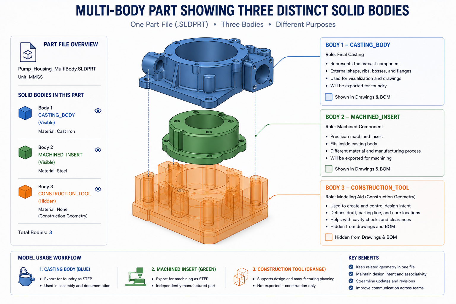
Multi-body modeling changes this by allowing features to create new, separate bodies rather than merging with the existing one. In SolidWorks, unchecking the ‘Merge Result’ checkbox when creating an extrusion produces a second independent body in the same part file. In Creo 7.0 and later, you can specify which body a feature belongs to. In Inventor, the Combine command lets you work with separate bodies and control whether they merge. The result is a single part file containing multiple distinct solid geometries, each with its own boundaries, its own identity, and its own role in the design.
Bodies vs. Features vs. Parts: Getting the Terminology Right
A feature is an operation: an extrusion, a cut, a fillet. A body is the geometric result of one or more features that share continuous solid material. A part is the file that contains one or more bodies. In standard single-body modeling, these three levels collapse into one: one part, one body, many features. In multi-body modeling, the part level is separated from the body level: one part file, multiple bodies, each body consisting of its own feature history.
This structural distinction matters because it determines what you can do with each body independently. Bodies within a multi-body part can be assigned different materials, different appearances, different custom properties, and in most platforms, different feature trees within the same overall feature tree. Bodies can be combined with each other through Boolean operations, split from each other using planes or surfaces, and individually extracted into separate part files when the design is ready for production.
The Solid Bodies Folder: Your Control Center
In SolidWorks, the Solid Bodies folder in the feature tree is the central management location for all bodies in the part. Every body appears in this folder with its own listing. You can right-click any body to hide it, make it transparent, select it for Boolean operations, assign a material to it, or insert it into a new part file. The folder also shows the body count, which is a quick sanity check: if you expect three bodies and the folder shows four, something merged or split unexpectedly during the last rebuild.
Creo uses a Bodies folder in the Model Tree with similar functionality, extended by the ability to assign a body to the Construction state, meaning it contributes to the modeling geometry but is excluded from mass properties calculations and from the physical product output. This construction body concept is one of the most powerful and least documented features in multi-body modeling, and we will cover it in depth in the technique sections below.
| Foundation Principle The key mental shift in multi-body modeling is separating the concept of a part file from the concept of a physical part. A part file is a container for geometry. It can contain one body that represents one physical component, or it can contain ten bodies that represent ten components, tool geometries, reference shapes, or construction aids. What matters is not how many bodies are in the file but whether each body has a clear, intentional role in the design workflow. |
Boolean Operations: The Engine of Multi-Body Modeling
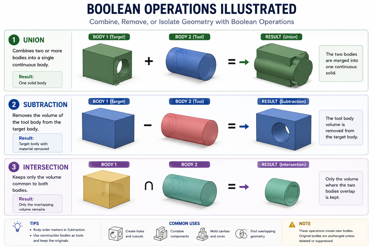
Boolean operations are the fundamental tools that give multi-body modeling its power. Named after mathematician George Boole, these operations combine two or more bodies using set logic to produce a new body or set of bodies. Every major CAD platform implements them. Understanding them thoroughly is the prerequisite for every advanced multi-body technique in this article.
Union (Add / Join): Combining Bodies Into One
A Boolean Union takes two separate bodies and combines them into a single continuous solid. All material from both bodies becomes part of the result. Internal interfaces between the two original bodies disappear. The result is one body with the combined volume of both inputs.
The most common use case is building complex geometry in stages: model each component of a complex form as a separate body, position them correctly relative to each other, then union them into a single body for downstream operations. This is often cleaner than trying to build the entire complex form in a single continuous feature sequence, especially when different sections of the form have different modeling logic.
Union is also the operation that finalizes weldment design. Individual weld members modeled as separate bodies for clarity during design are unioned into the finished weldment solid when the design is complete and ready for FEA or manufacturing output.
Subtraction (Cut / Remove): One Body Carving Another
A Boolean Subtraction removes the volume of one body from another. The subtracting body is used as a tool to cut material from the target body. The tool body itself is consumed by the operation and no longer exists as a separate body in the result. What remains is the target body with a void in the precise shape of the tool body that was subtracted from it.
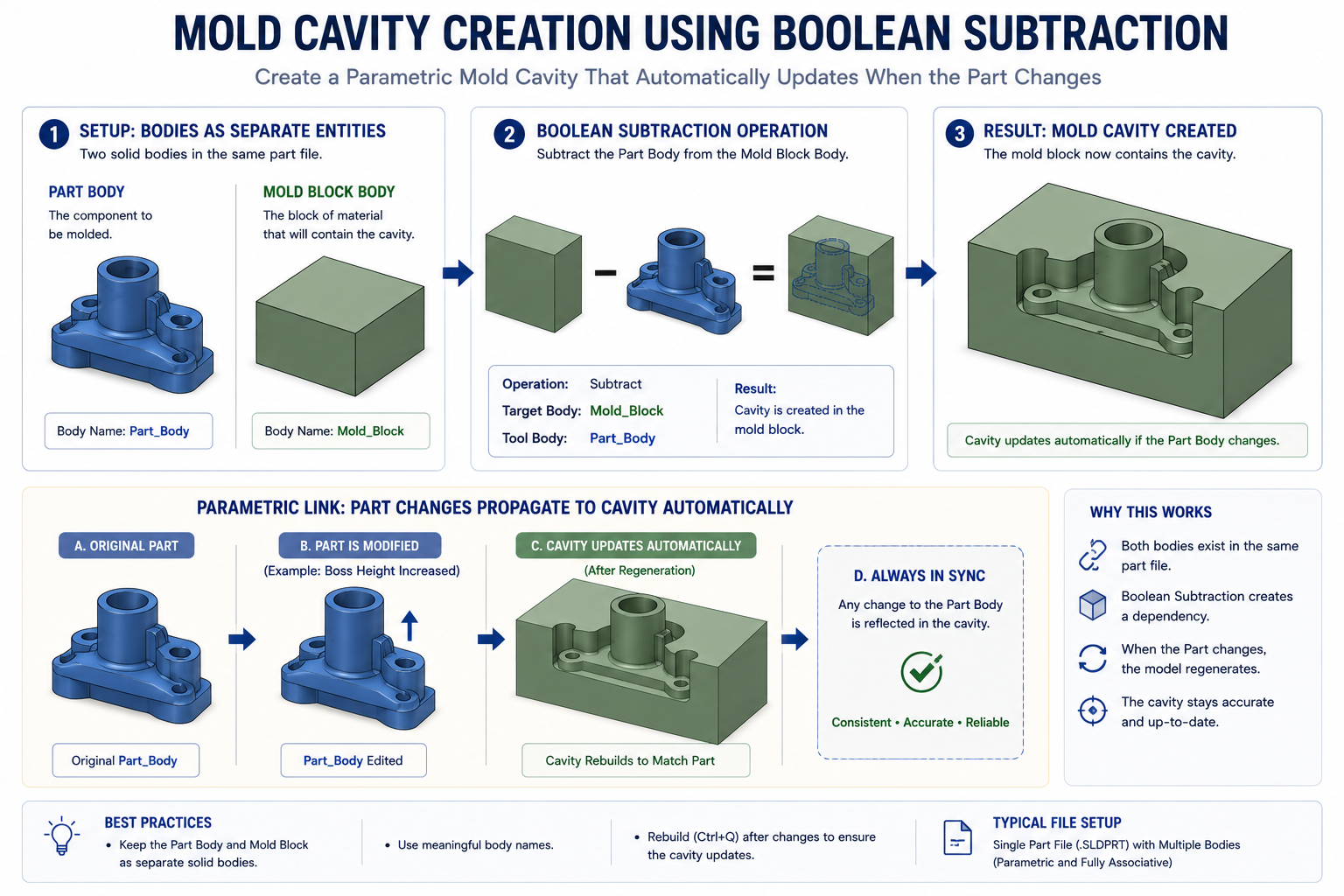
This operation is the foundation of mold and tooling design. You model the part to be molded as one body. You model the mold block as another body, positioned to enclose the part. A Boolean Subtraction removes the part body’s volume from the mold block body, leaving a cavity in the precise shape of the part. Because the cavity is derived directly from the part geometry, any change to the part automatically updates the cavity when the subtraction operation rebuilds, giving you a parametrically linked mold design without manual cavity reconstruction.
SolidWorks implements subtraction through the Combine tool with the Subtract option. The 2024 enhancement introduced the ability to make the main body transparent during a subtract operation, which makes it significantly easier to visually verify that the cavity is correct before committing to the operation. Creo, NX, CATIA, and Inventor all implement equivalent subtraction functionality under different menu names.
Intersection: Isolating Shared Volume
A Boolean Intersection keeps only the volume that is common to two overlapping bodies and discards everything else. The result is the geometric overlap region, expressed as a solid body.
Intersection is used less frequently than union or subtraction but has specific applications in quality analysis and complex geometry derivation. In quality analysis, the intersection of a nominal CAD model with a scan-derived body of a manufactured part can identify regions of material deviation. In complex geometry work, intersection can extract the exact shared region between two complex surfaces expressed as solids, which is sometimes cleaner than trying to derive the same shape through surface trimming operations.
The Indent Tool: A Specialized Subtraction for Clearance Creation
SolidWorks includes a specialized Boolean tool called Indent that is not available by name in all platforms but represents an important concept. The Indent tool creates a clearance void in one body based on the shape of another body, with a configurable offset. Instead of cutting the exact volume of the tool body, it cuts a slightly larger void based on the tool body’s shape plus a specified clearance value.
The industrial application is interference prevention in complex assemblies modeled within a single part: you can create the precise clearance pocket for a component in a housing without manually constructing the offset surface, letting the Indent tool handle the geometry derivation automatically. Any change to the component body updates the clearance pocket in the housing body through the parametric Indent feature.
The Master Model Technique: Designing Multiple Parts as One
The master model technique is the most strategically important application of multi-body modeling for engineers who design assemblies. It inverts the conventional design sequence: instead of building individual parts and assembling them, you model the entire assembly geometry in a single part file as multiple bodies, then extract each body into its own part file once the overall form is correct.
The advantage is profound: all interface geometry is inherently correct by construction. When you model two mating bodies in the same part file, their shared surfaces are identical by definition. There is no possibility of a mismatch between a housing bore and the shaft that fits into it because both geometries exist in the same coordinate space, driven by the same reference geometry. The fit is guaranteed at the modeling stage, before a single mate has been defined in an assembly.
How the Master Model Workflow Operates
The sequence is deliberately staged. In the first stage, you build the complete product geometry in a single part file as multiple bodies. Each body represents one component of the eventual assembly. Because they share the same coordinate system and reference geometry, all interfaces, clearances, and fit conditions are defined and visible in one place. Interference can be detected immediately by visual inspection or by running an interference check within the part environment.
In the second stage, once the overall geometry is validated, you extract each body into its own part file using the Save Bodies command in SolidWorks, the Extract Body or Publish Geometry feature in Creo, the Derive Part command in Inventor, or the WAVE Geometry Linker in NX. The extracted part files are linked to the master: changes to the master body propagate to the extracted part files, maintaining the parametric connection between the overall form and the individual components.
In the third stage, each extracted part file receives its own detailed features: the additional machining operations that cannot be captured in the master body, the thread specifications, the surface finish annotations, and the drawing. The assembly is built by placing the extracted part files together, which is fast because the mating geometry is already guaranteed to be correct.
Master Model for Surface-Dominated Design
The master model technique is especially powerful in industrial design and consumer product development, where the outer surface form of a product must be established before individual parts are split from it. Consider the shell of a handheld device: the overall ergonomic form, the button openings, the screen aperture, and the speaker grille geometry are all properties of the product’s outer surface, not of any individual part.
A surface designer models this outer form as a single surface body. A CAD engineer then uses that surface as the reference for splitting the form into its component parts: front shell, back shell, internal chassis, button cap. Each part is derived from the master surface by thickening, trimming, and splitting, ensuring that all part edges, parting lines, and split interfaces are geometrically consistent with the original design intent. This workflow is standard practice in consumer electronics and automotive interior design.
| Real-World Application A medical device company redesigned a handheld diagnostic tool using the master model technique after their previous approach of building parts independently had resulted in chronic interface mismatches that required assembly shimming. The master model approach meant that the first physical prototype assembled without shimming for the first time in the product’s history. The investment in learning the technique was recovered in the first prototype build cycle. |
Weldments: Multi-Body Modeling’s Killer Application
If there is one application that demonstrates the productivity advantage of multi-body modeling more convincingly than any other, it is weldment design. A weldment is a fabricated structure built by welding structural profiles together: I-beams, square tubes, round tubes, angle iron, channel sections, and custom profiles. In a traditional assembly approach, every individual cut piece of structural steel is a separate part file with its own part number, its own drawing, and its own BOM entry. A complex machine frame with two hundred structural members generates two hundred part files, two hundred drawings, and a BOM that no purchasing team wants to work with.
Weldment modeling in SolidWorks collapses this entirely. Structural profiles are defined using library profiles and path sketches. The CAD tool places the profiles along the sketch paths, trims them at intersections, and manages them as separate bodies within a single part file. The result is a complete structural frame modeled as one file, with each member as a body, and a Cut List (not a BOM) that automatically identifies identical members, calculates lengths, and groups them for manufacturing.
The Cut List: How Weldments Handle BOM Differently
The Cut List is the weldment-specific equivalent of the BOM. Unlike a standard BOM that lists every component as a unique item, the cut list identifies groups of identical members. If your frame has twelve identical 500mm lengths of 50x50x3mm square tube, the cut list shows one line item for that profile with a quantity of twelve. The purchasing team orders twelve identical cuts. The welder receives one instruction for that profile size.
This automatic grouping is one of the most practically valuable features in the entire CAD weldment workflow. In a complex frame with many identical members, it eliminates both the modeling overhead of creating individual part files and the purchasing overhead of processing individual BOM line items. Changing the length of a profile type propagates through all instances of that profile automatically, because they are driven by the same sketch path.
Custom Weldment Profiles
The standard profile libraries cover the most common structural sections, but engineering applications frequently require custom profiles: proprietary extrusions, non-standard channels, composite sections, or profiles designed for a specific structural application. Most platforms allow custom profiles to be created as sketch profiles and added to the weldment library, after which they behave identically to standard profiles in the weldment workflow.
Creating a well-organized custom profile library is a significant one-time investment that pays dividends across every weldment project that uses those profiles. A mechanical engineering team at a custom machine builder that standardizes on five custom aluminum extrusion profiles should build those profiles into the library once, document their dimensions and material properties, and draw from the library for every subsequent frame design rather than rebuilding the profiles each time.
Weldment Performance: Why Multi-Body Wins Over Assembly for Frames
There is a practical performance argument for weldment modeling over assembly modeling that does not get enough attention in CAD educational content. An assembly with two hundred individual part files must load and resolve two hundred separate file references every time it opens. Every mate between parts must be recalculated. Assembly rebuild times scale with part count.
A weldment of two hundred members in a single part file loads one file. There are no external references to resolve, no mates to recalculate. Rebuild performance is dramatically better because the CAD engine is operating within a single part context rather than managing a complex network of inter-file dependencies. For large structural assemblies where fast iteration speed matters, this performance advantage alone can justify the weldment approach over a conventional assembly.
Mold and Tooling Design: Where Boolean Subtraction Earns Its Keep
Mold and tooling design is the domain where multi-body modeling, and specifically Boolean subtraction, is most clearly the correct approach. The relationship between a molded part and its mold cavity is inherently a geometric derivation relationship: the cavity is the inverse of the part. Any workflow that treats them as separately modeled entities loses this derivation link and requires manual updates to the cavity every time the part changes.
The Parametric Mold Cavity Workflow
The parametric approach to mold cavity creation using multi-body modeling follows a clean logical sequence. You model the part to be molded as the primary body, incorporating all the geometric details that the mold must capture. You model the mold block as a second body, sized and positioned to fully enclose the part with appropriate stock allowance on all sides.
You then apply a Boolean Subtraction that removes the part body’s volume from the mold block body. The operation leaves a cavity in the mold block that is the precise negative of the part geometry. Because this cavity is a parametric feature driven by the part body geometry, any subsequent change to the part body automatically updates the cavity when the model rebuilds. The mold designer does not need to manually adjust cavity surfaces, draft angles, or interface geometry after a part change. The Boolean feature handles it.
This parametric linkage is particularly valuable during the iterative design phase, when part geometry is still evolving and the mold design must evolve in parallel. In a traditional workflow, every part change requires a corresponding manual update to the mold cavity. In the multi-body parametric workflow, the mold updates automatically with each part revision, allowing the mold and part to be co-developed without manual synchronization overhead.
Parting Line and Cavity Split Operations
Beyond the basic cavity creation, mold design requires splitting the mold block into core and cavity halves along a parting surface that allows the mold to open and release the part. The Split feature in SolidWorks, and equivalent features in other platforms, uses a surface or sketch to divide one body into two or more bodies along a defined boundary. Applied to the mold block body, this split operation produces the core and cavity halves that will become the two sides of the physical mold tool.
The parting surface itself can be modeled as a surface body within the same part file, derived from the part geometry using parting line analysis tools. This keeps the entire mold design, including the part, the mold block, the parting surface, and the split core and cavity halves, within a single integrated part file where all elements are parametrically linked and update together when any upstream geometry changes.
Side Actions and Lifters as Additional Bodies
Complex molded parts with undercuts, holes perpendicular to the mold opening direction, or recesses that cannot be demoulded in the primary opening direction require side actions (slides) or lifters. These mechanisms move independently of the primary mold opening and must have their own geometry, clearances, and interface surfaces defined precisely.
Multi-body modeling handles this by representing each slide or lifter mechanism as its own body or set of bodies within the mold part file. Boolean operations define the interaction geometries: the slide body is subtracted from the mold block to create the slide pocket, the part body geometry is applied to the slide face to create the forming surface. All interactions are captured in one file, all parametrically linked to the part geometry.
Construction Bodies: The Advanced Technique Most Engineers Miss
Construction geometry is a familiar concept in CAD sketching: reference lines and arcs that guide the creation of real geometry but do not themselves become part of the model output. The same concept applied at the body level is far less widely understood, and it represents one of the most powerful advanced techniques in multi-body modeling.
A construction body is a solid body within a multi-body part that is used purely as a modeling tool or reference geometry. It is not intended to become a physical part, it does not contribute to mass properties calculations, and it is suppressed or hidden before the model is used for manufacturing output. Its purpose is to enable geometric operations that would be difficult or impossible to achieve through normal feature creation alone.
Using Construction Bodies as Machining Simulation Tools
One of the most useful applications of construction bodies is simulating a machining operation to verify that the machine will correctly produce a desired geometry without creating a dedicated simulation environment. You model the cutting tool as a construction body, sized and shaped to represent the actual end mill, drill, or form tool that will be used. You position it at the intended machining location. You apply a Boolean Subtraction using the tool body to remove its volume from the workpiece body.
The result is the workpiece geometry after the machining operation, produced by the same geometric logic as the actual machining process. You can verify that the resulting cavity geometry matches the design intent, that the tool can access the feature without interference, and that the resulting geometry is achievable with the specified tool geometry. The construction tool body is then hidden or suppressed, leaving the machined workpiece geometry as the visible model output.
Construction Bodies for Casting-Plus-Machining Workflows
A common multi-body modeling workflow for cast-and-machine parts uses construction bodies to represent manufacturing stages. The casting body represents the part as it comes out of the mold, including all casting-specific geometry: parting line draft, casting allowances, and rough surfaces. A set of machining construction bodies represents the material removed by each machining operation.
Boolean operations applied sequentially from the casting body and construction machining bodies produce the final machined part geometry. Because each stage of manufacturing is explicitly modeled as a body or construction body, the design captures not just the final part geometry but the manufacturing sequence that produces it. This is particularly valuable for components where the relationship between the casting geometry and the machined geometry must be verified for feasibility before tooling is committed.
Construction Bodies in Generative Design Workflows
Modern generative design and topology optimization tools, available in Fusion 360, NX, and as integrated modules in SolidWorks and Creo, use construction body concepts under different names. Preserve regions are bodies that define geometry that must not be removed by the optimization algorithm (interface surfaces, load points, attachment features). Obstacle regions are construction bodies that define spatial regions the optimized geometry must avoid (clearance volumes for adjacent components, assembly access spaces).
Setting up these optimization inputs is itself a multi-body modeling task: you define the design space as one body, the preserve regions as additional bodies, and the obstacle regions as further bodies, all within the same part file. The optimization algorithm operates on this multi-body setup to produce optimized geometry that meets the structural requirements while respecting the manufacturing and assembly constraints represented by the construction bodies.
Multi-Material Body Assignment and Simulation
One of the practical advantages of multi-body modeling that is rarely covered in introductory material is the ability to assign different materials to different bodies within the same part file. This capability directly affects mass properties calculations, simulation accuracy, and documentation of multi-material components.
A bracket that is cast from aluminum but has a steel insert press-fitted into a bore can be modeled as two bodies: the aluminum casting body and the steel insert body. Assigning aluminum alloy to the first body and tool steel to the second allows the CAD tool to calculate accurate mass properties for the complete component, accounting for the density difference between the two materials. The reported mass, center of gravity, and moments of inertia reflect the actual physical component rather than a single-material approximation.
Multi-Material for Overmolded and Insert-Molded Parts
Overmolding and insert molding produce components that are genuinely multi-material by design: a rigid substrate material overmolded with a soft grip material, a metal insert embedded in a plastic housing, a hard plastic core with a soft-touch surface skin. These components are single assemblable items but they contain multiple materials with different properties.
Multi-body modeling with material assignment provides a clean way to document these components: one body per material, each assigned its appropriate material specification, with the combined mass properties reflecting the multi-material reality. The drawing can reference both bodies, calling out the substrate material on one detail view and the overmold material on another, with a single part file serving as the authoritative geometry source for the entire component.
Using Multi-Body Models for FEA and Structural Simulation
Finite Element Analysis of multi-material components benefits significantly from multi-body models with correct material assignments. When a multi-body part is imported into an FEA environment, the material boundaries are preserved as distinct regions within the mesh. The solver applies the correct material properties to each region, producing stress and deformation results that account for the stiffness differences between materials at their interface.
Without multi-body modeling and material assignment, the same analysis requires either meshing the component as a uniform material (which introduces error at material interfaces) or preparing separate geometry for each material region (which requires manual effort to ensure the interface surfaces are correctly coincident). The multi-body approach provides both geometric accuracy and material accuracy with no additional preparation work.
Body Management: Naming, Organization, and Discipline
A multi-body part with two or three bodies is manageable with minimal organization effort. A multi-body part with fifteen bodies, representing a complete assembly modeled before extraction, or a mold with part body, core, cavity, slide bodies, and construction tool bodies, becomes genuinely difficult to work with unless body management discipline is applied from the beginning.
Naming Every Body Descriptively
The default body names in most CAD platforms are uninformative: Body 1, Body 2, Solid Body 3. In a part with many bodies, these names tell you nothing about which body represents what. Name every body immediately upon creation with a name that describes its role in the design: Casting-Aluminum-Main, MachiningTool-EndMill-D12, CavityBlock-Steel, SlideAction-Left, ConstructionTool-Draft-Check. These names make the Solid Bodies folder readable, make Boolean operation selections unambiguous, and make the model understandable to any engineer who opens it.
Most platforms allow body renaming directly in the Solid Bodies folder or Model Tree. In SolidWorks, right-click the body in the Solid Bodies folder and select Rename. In Creo, the body name is editable in the Bodies folder properties. Make renaming an immediate habit: name the body at the moment you create it, before you forget its intended role.
Color Coding for Visual Clarity
Assign distinct colors or appearances to each body to make them visually distinguishable in the graphics window. In a mold design with a part body, a mold block body, and multiple slide bodies, color-coding makes it immediately obvious which body is which without reading the feature tree. Use consistent color conventions across your team: for example, blue for part bodies, gray for tooling bodies, transparent yellow for construction bodies, red for interference check regions.
This visual coding costs nothing and saves significant time during modeling and review. The mental overhead of identifying which body you are looking at, every time you need to select one for a Boolean operation or a property assignment, accumulates into a meaningful time cost over the life of a complex multi-body part.
Folder Organization in the Feature Tree
In SolidWorks, features can be organized into folders within the feature tree. In a multi-body part, use folders to group the features that belong to each body: a ‘CastingBody’ folder containing all the features that build the casting geometry, a ‘MachiningFeatures’ folder containing the Boolean operations that add machined detail, a ‘ToolingBodies’ folder containing the construction body features. This folder structure makes the feature tree navigable rather than a flat list of hundreds of operations with no organizational logic.
Body Management Conventions Reference |
Multi-Body vs Assembly: When to Use Each
The most practically important question for any engineer learning multi-body modeling is when to use it instead of a conventional assembly. The honest answer is that neither approach is universally superior. Each is the right tool for specific design situations, and understanding the criteria that distinguish those situations is more valuable than a blanket rule in either direction.
| Criterion | Use Multi-Body Part | Use Separate Assembly | Key Reason |
| Parts made from same stock in one operation | Yes | No | Same machining setup, same raw material tracking |
| Parts with different materials | Usually No | Yes | BOM and material tracking require separate part files |
| Complex weldments with cut list | Yes | No | Cut list BOM from weldment profiles is faster than assembly BOM |
| More than 20 discrete components | No | Yes | Assembly mates provide positional control at scale |
| Mold core and cavity design | Yes | No | Boolean subtraction logic is native to multi-body workflow |
| Parts that will be separately purchased | No | Yes | Each purchased part needs its own part number and file |
| Concept modeling for part count reduction | Yes | No | Explore splits and combinations before committing to assembly structure |
| Casting with machined features | Yes (then split) | No initially | Model rough casting, add machining bodies, then extract |
| Simulation of part interactions under load | Yes (multi-material) | Yes (contact sets) | Depends on FEA tool and analysis type required |
| PDM and lifecycle managed separately per part | No | Yes | PDM revision control requires one file per controlled item |
Reading the Decision Table Correctly
The key insight from the decision table is that multi-body modeling excels when bodies are geometrically interdependent and share manufacturing context, and assembly modeling excels when components are independently procured, independently revised, or managed through separate lifecycle processes. These are different kinds of complexity: geometric complexity favors multi-body, organizational and lifecycle complexity favors assembly.
Most real-world products involve both kinds of complexity in different areas of the design. A machine frame is geometric complexity: it is one structural object made by welding, and multi-body weldment modeling is clearly correct. The motors, gearboxes, and sensors mounted to that frame are organizational complexity: they are separately purchased, separately revised, and separately managed, and assembly modeling is clearly correct for them. The full product design uses both approaches in the areas where each excels.
The Hybrid Approach: Master Model Leading Into Assembly
The most sophisticated engineering teams use a hybrid: multi-body master modeling to establish geometry and interface relationships, followed by body extraction into individual part files, followed by assembly of those parts. This sequence captures the geometric integrity advantages of multi-body modeling at the concept and detail design stages while ending up with the file structure of a conventional assembly for PDM management, drawing generation, and procurement.
The transition from master model to extracted assembly is the workflow that many engineers find most difficult to implement, because it requires understanding both multi-body techniques and assembly management simultaneously. But for products where interface fit is critical and design iteration speed matters, it is consistently the most effective approach available in modern parametric CAD.
Multi-Body Modeling Across CAD Platforms
Multi-body modeling is not a SolidWorks-exclusive capability. Every major professional CAD platform supports it, though implementation details, feature names, and tool availability vary. The following table maps the key multi-body capabilities across platforms to help engineers working in different environments locate the equivalent functionality.
| CAD Platform | Multi-Body Support | Boolean Operations | Body Extract Tool | Notable Capability |
| SolidWorks | Full (native) | Add, Subtract, Intersect (Combine) | Save Bodies / Insert into New Part | Weldment profiles, Indent tool for cavity creation |
| PTC Creo 7.0+ | Full (from v7.0) | Merge, Cut, Mirror bodies | Extract Body / Publish Geometry | Verification instances, construction body state |
| Autodesk Inventor | Full (native) | Combine (Join, Cut, Intersect) | Derived Part / Shrinkwrap | Multi-body for weldments, iPart with bodies |
| Siemens NX | Full (native) | Unite, Subtract, Intersect | WAVE Geometry Linker | Industry-leading for mold and die, synchronous editing of bodies |
| CATIA V5/V6 | Full (native) | Boolean Operations in Part Design | Publish / External References | Multi-body standard in complex surface-solid workflows |
| Autodesk Fusion 360 | Full (native) | Combine (Join, Cut, Intersect) | Break Link / Save As Component | Streamlined for additive manufacturing workflows |
| Onshape | Full (native) | Boolean (Add, Subtract, Intersect) | Add to Assembly as separate part | Cloud-native, real-time collaboration on multi-body parts |
Siemens NX deserves specific mention for its WAVE Geometry Linker, which is arguably the most powerful body extraction and linking tool available in any commercial CAD platform. WAVE (What-if Alternative Value Engineering) creates associative links between bodies across part files, allowing geometry changes in a master body to propagate through a linked chain of derived part files automatically. It is the enterprise-scale implementation of the master model concept, used extensively in aerospace and automotive programs where hundreds of parts must maintain geometric consistency with master assembly structures.
Frequently Asked Questions
Q: What is multi-body modeling in CAD?
Multi-body modeling is the technique of working with multiple independent solid bodies within a single CAD part file. Instead of the conventional approach where one part file contains one continuous solid body, multi-body modeling allows a single file to contain two, ten, or more distinct bodies that can each have their own geometry, material assignment, and role in the design workflow. Bodies can be combined, subtracted from each other, intersected, and individually extracted into separate part files using Boolean operations and body management tools.
Q: When should I use multi-body modeling instead of an assembly?
Use multi-body modeling when bodies are geometrically interdependent and share manufacturing context: weldments, mold and tooling design, cast-and-machine parts, and master model workflows where interface geometry must be established before individual parts are split out. Use assembly modeling when components are independently purchased, independently revised, managed under separate lifecycle processes, or when the component count makes assembly mates the more appropriate positional control mechanism. Most complex products use both approaches in different areas of the design.
Q: What are Boolean operations in multi-body CAD modeling?
Boolean operations are geometric operations that combine two solid bodies using set logic. Union (also called Add or Join) combines two bodies into one continuous solid. Subtraction (also called Cut or Remove) removes the volume of one body from another, leaving a void in the shape of the removed body. Intersection keeps only the volume that is shared by two overlapping bodies. These three operations are the foundation of all multi-body modeling workflows, from mold cavity creation to weldment assembly to construction body-based machining simulation.
Q: What is the master model technique in CAD?
The master model technique is a multi-body modeling workflow where the complete geometry of an assembly is modeled in a single part file as multiple bodies, one body per component. This establishes all interface geometry as inherently correct by construction, since all bodies share the same coordinate system and reference geometry. Individual bodies are then extracted into separate part files using the platform’s body extraction tools, and the assembly is built from those extracted files. Changes to the master body propagate to extracted parts, maintaining parametric consistency between the overall design and individual components.
Q: How does multi-body modeling improve mold design?
Multi-body modeling enables parametrically linked mold cavity creation using Boolean subtraction. The part to be molded is modeled as one body. The mold block is modeled as a second body. A Boolean Subtraction removes the part body’s volume from the mold block, creating a cavity in the precise shape of the part. Because this cavity is a parametric feature, any change to the part body automatically updates the cavity when the model rebuilds. This eliminates the manual cavity reconstruction that conventional mold design workflows require after every part revision.
Q: What is a construction body in multi-body CAD modeling?
A construction body is a solid body used purely as a modeling or reference tool within a multi-body part, not intended to become part of the physical product output. Construction bodies enable complex operations such as machining simulation, casting geometry verification, and generative design boundary definition. They are suppressed or hidden before the model is used for manufacturing output. In Creo, the Construction state flag formally designates a body as non-physical, excluding it from mass properties calculations. In other platforms, the same concept is implemented through body suppression and hidden state management.
Q: Can multi-body parts be used in assemblies and drawings?
Yes. Multi-body parts can be placed in assemblies like any other part file, where all bodies within the part move together as a unit. Individual bodies within a multi-body part can also be extracted into separate part files using the platform’s Save Bodies, Extract Body, or equivalent tools, and those extracted files can be individually placed in assemblies. For drawings, individual bodies can be shown in separate views with independent annotations, or bodies can be hidden selectively to show only the geometry relevant to a specific drawing view.
Conclusion:
The engineers who use multi-body modeling most effectively are not those who know the most button sequences or who have memorized every Boolean operation option. They are the engineers who have internalized a fundamentally different way of thinking about the relationship between a CAD file and a physical design.
A CAD file is not a representation of one physical object. It is a workspace for geometric reasoning. Multiple bodies in that workspace can represent physical components, manufacturing tools, reference geometries, simulation boundaries, and construction aids simultaneously. The workspace contains whatever geometry is needed to solve the design problem correctly, and it outputs to the manufacturing world only the bodies that represent real physical things.
Boolean operations are not just geometry manipulation tools. They encode the logic of manufacturing processes: subtraction encodes material removal, union encodes welding and bonding, intersection encodes overlap analysis. Using them deliberately means embedding manufacturing process knowledge directly into the geometry creation workflow.
And body management discipline, including naming, color coding, material assignment, and construction body governance, is what separates a multi-body model that is genuinely useful from one that is technically correct but impossible to work with three months after it was created.
Start with one technique from this article. If you design weldments, try the weldment workflow in your platform. If you design molds, try the Boolean subtraction cavity technique. If you design assembled products with critical interfaces, try modeling two adjacent components as bodies in a single master file before extracting them. Each technique you internalize adds a new kind of problem you can solve with confidence.
Continue building your CAD expertise with our guides on design intent, parametric modeling best practices, design tables for product families, and CAD file management for engineering teams.
Leave a Reply