Computer-Aided Design (CAD) software is one of the most transformative technologies in the history of engineering, architecture, and manufacturing. In four decades it has replaced every drawing board, eliminated most of the calculation errors that cost lives in engineered structures, compressed product development timelines from years to months, and made it possible to design objects of extraordinary geometric complexity with precise dimensional control.
And yet, for all its ubiquity, CAD software is profoundly misunderstood , even by many of the engineers, architects, and designers who use it daily. Most people know the name of the tool they use. Far fewer understand the category that tool belongs to, why that category exists, how it relates to other CAD categories, or what the technology actually does under the surface to enable the work it supports.
This pillar guide closes that gap. It explains CAD software from first principles: what it is, where it came from, how it is categorised into distinct types, what each type does and why it was invented, how the major tools within each type compare, how CAD fits into the broader product development and construction workflow, what file formats it uses and why they matter, how the technology is changing with AI and cloud computing, and what career paths are built on it. It is the most comprehensive, readable, and practically useful guide to CAD software available outside of a university textbook.
| Quick Definition: CAD software (Computer-Aided Design software) is any software application used to create, modify, analyse, and document designs with a precision and efficiency that manual drawing cannot match. It ranges from 2D drafting programs that produce technical drawings to parametric 3D solid modelling tools, architectural BIM platforms, aerodynamic simulation environments, and AI-assisted generative design systems. |
What Is CAD Software? A Complete Definition
CAD software is a category of computer application that enables engineers, architects, designers, and technicians to create precise digital representations of physical objects, structures, and systems. The word “design” in Computer-Aided Design encompasses both the creative act of conceiving a new object and the analytical act of verifying that it will perform as required , making CAD simultaneously a creative and an engineering tool.
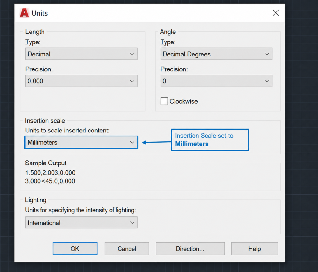
At the most fundamental level, a CAD software application provides a digital environment in which geometric objects (lines, curves, surfaces, solids) can be created, positioned, dimensioned, and modified with precision measured to fractions of a millimetre or micron. Unlike a general-purpose drawing application (such as Adobe Illustrator or Microsoft PowerPoint), CAD software models geometry in actual physical coordinates , every object has a precise location, dimension, and relationship to every other object, defined in the same units of measurement (millimetres, inches, metres) that the physical object will eventually be produced in.
What Makes CAD Different from General Drawing Software
| Feature | CAD Software | General Drawing / Illustration Software |
| Coordinate precision | Exact geometric coordinates , objects are positioned to engineering precision | Approximate pixel or point positions , not dimensionally accurate |
| Units | Real-world measurement units (mm, in, m) throughout | Arbitrary canvas units , not calibrated to physical dimensions |
| Object relationships | Geometric constraints and parametric relationships between objects | Objects are independent , no geometric relationships |
| Dimensional accuracy | Dimensions are exact and queryable , DIST, AREA, MASS PROPERTIES commands | Dimensions are approximations , not guaranteed accurate |
| Manufacturing output | Produces drawings and data directly usable for manufacturing, fabrication, and construction | Produces artwork for visual communication, not manufacturing |
| File formats | Engineering formats: DWG, DXF, STEP, IGES, STL, IFC | Graphic formats: AI, PDF, SVG, PSD, PNG |
The Three Core Uses of CAD Software
All CAD software serves three fundamental purposes, which together define what computer-aided design means in practice:
- Design and modelling: Creating the geometric representation of a product, structure, or system , the digital model from which everything else flows.
- Analysis and verification: Confirming that the design meets its requirements , structurally sound, thermally stable, manufacturable, collision-free , before anything physical is built.
- Documentation and communication: Producing the drawings, specifications, bills of materials, and data files that communicate the design to manufacturers, fabricators, constructors, and clients.
| Scale of Impact: According to Grand View Research, the global CAD software market was valued at $12.0 billion in 2024 and is projected to reach $17.5 billion by 2030, growing at a CAGR of 6.5%. Architectural CAD software alone is projected to reach $30.17 billion by 2026, driven by cloud-based BIM adoption, AI-assisted design, and global construction digitisation. CAD is no longer a specialist engineering tool , it is infrastructure for the entire built environment, product manufacturing, and energy systems industries. |
The History of CAD Software: From Drawing Boards to AI
The history of CAD software is one of the most important stories in the history of technology. It is the story of how an entire profession was transformed from pencil-and-paper craft into digital engineering in less than 50 years.
1960s: The Birth of Computer-Aided Design
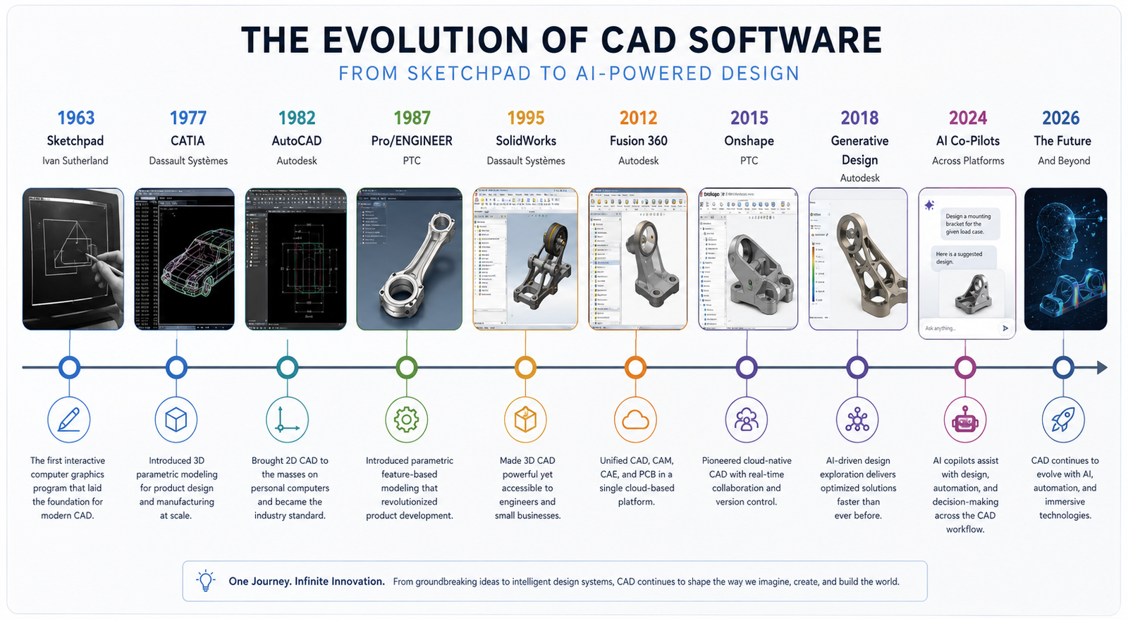
The concept of computer-aided design was born in 1963 when Ivan Sutherland, a PhD student at MIT, presented Sketchpad , the first interactive computer graphics system , in his doctoral thesis. Sketchpad allowed users to draw geometric shapes on a CRT display using a light pen and introduced fundamental CAD concepts including constraints, object hierarchies, and parametric editing that are still central to modern CAD software 60 years later.
Sutherland’s work inspired automotive and aerospace companies to explore computer graphics for engineering design. General Motors partnered with IBM to develop DAC-1 (Design Augmented by Computer) for automobile body design in 1963. Lockheed Aviation developed CADAM (Computer Augmented Design and Manufacturing) in the late 1960s. These early systems ran on room-sized mainframe computers and cost millions of dollars , accessible only to the largest industrial corporations.
1970s: Proprietary Workstation CAD
The 1970s brought the first commercial CAD systems. CATIA was developed by Dassault Systemes (originally for Dassault Aviation) beginning in 1977. CADAM was acquired by Lockheed and commercialised. Unigraphics (the predecessor to Siemens NX) and Pro/ENGINEER (the predecessor to PTC Creo) were both developed in this decade. These systems ran on dedicated engineering workstations costing $50,000 to $150,000 per seat , still expensive, but beginning to be accessible to mid-sized engineering firms.
The critical innovation of this era was the introduction of 3D wireframe and surface modelling: the ability to represent the full three-dimensional form of an object in the computer rather than just its 2D projections. This transformed CAD from an expensive drafting tool into a genuine design tool, enabling engineers to visualise, analyse, and refine 3D geometry before physical prototypes were built.
1982: AutoCAD and the Personal Computer Revolution
The most consequential event in the history of CAD software was the release of AutoCAD by Autodesk on 1 December 1982 at COMDEX in Las Vegas. AutoCAD was the first fully functional CAD program to run on a personal computer. At an initial price of $1,000 (compared to $50,000+ for competing workstation CAD systems), it democratised CAD access and within a decade had become the global standard for technical drawing, destroying the commercial drawing board market entirely.
AutoCAD’s introduction did more than make CAD affordable. It established the DWG file format as the universal language of engineering drawings, created the concept of a command-line interface for precision CAD input, and set the user interaction paradigm that most 2D CAD tools still follow today.
1987-1995: The Parametric Revolution
The next transformational shift came with the introduction of parametric feature-based 3D solid modelling. PTC released Pro/ENGINEER in 1987, the first commercially successful fully parametric 3D CAD system. Pro/ENGINEER’s fundamental innovation was that every feature in a 3D model was defined not just by its geometry but by its parameters (dimensions, constraints, relationships to other features) and its creation intent (this boss is on the top face of this body, at this offset from this edge).
This meant that changing a parameter automatically updated the entire model: change the hole diameter and every related feature updated accordingly. The parametric approach was a profound shift from direct geometry manipulation , it encoded the engineer’s design intent into the model rather than just its current geometry. SolidWorks launched in 1995 with a Windows-native interface and significantly lower cost, bringing parametric 3D CAD to the mainstream mechanical engineering market.
2000s: Integration, Simulation, and PLM
The 2000s brought the integration of CAD with simulation (CAE), manufacturing programming (CAM), and product lifecycle management (PLM). ANSYS, MSC Nastran, and SolidWorks Simulation brought finite element analysis to the design engineer’s desktop. Mastercam, Fusion 360 (CAM), and NX CAM integrated manufacturing programming with the design model. Dassault’s 3DEXPERIENCE platform and Siemens’ Teamcenter provided the PLM backbone to manage complex multi-disciplinary product data across engineering organisations.
2010s-Present: Cloud, Collaboration, AI, and Generative Design
The defining developments of the current era are the shift to cloud-native CAD (Onshape launched 2015, Fusion 360 hybrid cloud launched 2013), the integration of AI and generative design (Autodesk introduced generative design in Fusion 360 in 2018), and the rapid growth of BIM (Building Information Modelling) as the standard for construction project design and coordination. In 2024-2026, conversational AI interfaces (CAD assistants, natural language design query tools, AI-powered topology optimisation) are beginning to reshape the daily workflow of CAD practitioners for the first time since the introduction of parametric modelling.
How CAD Software Works: The Core Technology Concepts
Understanding what happens inside a CAD software application when you draw a line, extrude a profile, or run a simulation makes the entire landscape of CAD types and tools more logical. Most of the distinctions between CAD tools trace back to fundamental differences in the underlying technology.
Geometric Kernels: The Mathematical Engine
Every 3D CAD tool is built on a geometric kernel , a mathematical library that handles the representation and manipulation of 3D geometry. The two dominant commercial geometric kernels are Parasolid (owned by Siemens) and ACIS (owned by Spatial Corporation / Dassault). SolidWorks, NX, Solid Edge, and many others use Parasolid. AutoCAD 3D solid modelling, Inventor, and some others use ACIS. CATIA uses its own proprietary kernel.
The geometric kernel determines what types of geometry the CAD tool can represent, how accurately it handles complex operations like Boolean intersections and filleting, and what output formats it can produce. This is why files exported from one CAD tool often need to be translated through a neutral format (STEP, IGES) when moving to a different tool , the underlying geometry representations are different.
Feature Trees and Parametric History
Parametric 3D CAD tools maintain a feature tree (also called a model tree or design tree) , a chronological record of every operation performed to create the 3D model. The feature tree is the model’s construction history: it records that the base extrusion came first, then a fillet was applied, then a hole was added, then a pattern of holes was created.
The feature tree is what makes parametric CAD models editable by intent rather than by geometry. Changing the diameter of the original hole also updates the pattern of holes, because the pattern references the parent hole’s geometry. Parametric models can be updated by editing parameters anywhere in the feature tree, and the model rebuilds from that point downward.
Constraint Solving
2D CAD sketches and 3D assembly positions are governed by constraint solvers , mathematical engines that enforce geometric relationships between objects. A coincident constraint forces two points to occupy the same location. A tangent constraint forces a line to be tangent to a circle. A perpendicular constraint forces two lines to meet at 90 degrees. When constraints are fully satisfied, the sketch or assembly is fully constrained: it cannot move or deform except by changing the parameters or constraints themselves. Constraint solving is the foundation of parametric design intent.
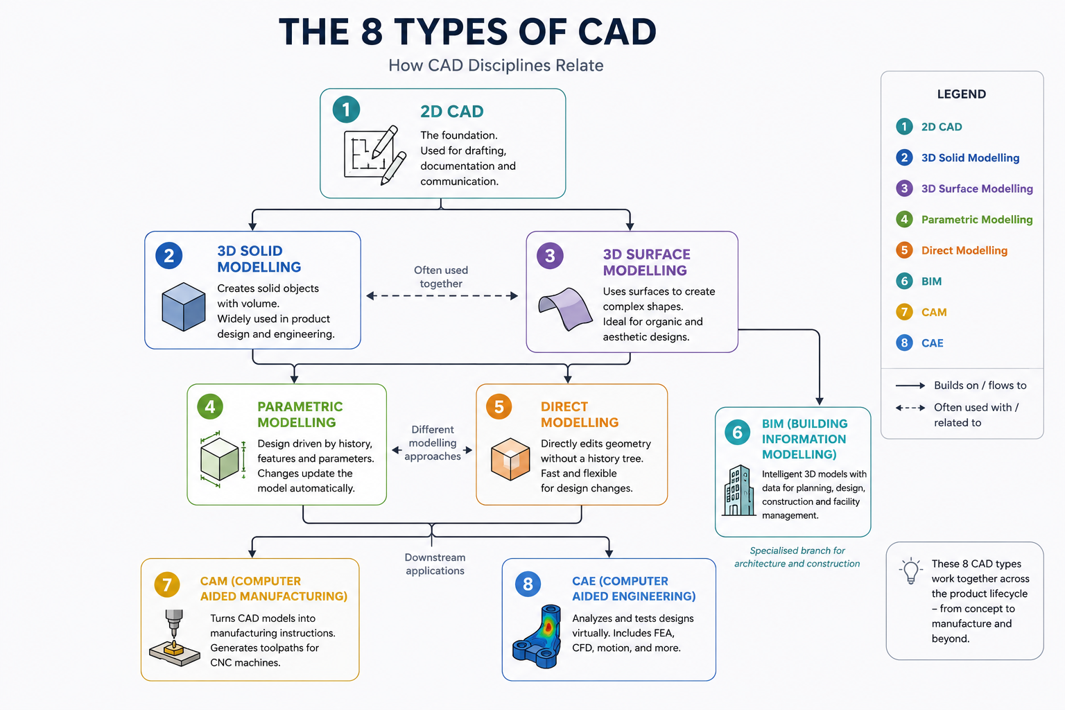
The 8 Types of CAD Software Explained
CAD software is not a single technology. It is a family of distinct types, each developed to address a specific design, analysis, or documentation problem. Understanding the eight primary types of CAD software is the conceptual foundation for understanding the entire CAD landscape.
| Type | Primary Purpose | Output Produced | Key Technologies | Representative Tools |
| 2D CAD | Technical drawing and documentation | Engineering drawings, construction plans, schematics | Vector geometry, layers, annotation, plotting | AutoCAD, AutoCAD LT, LibreCAD, QCAD |
| 3D Solid Modelling | Creating 3D volumetric models for design and manufacturing | 3D solid models, assembly models, rendered visualisations | B-rep solid geometry, feature trees, Boolean operations | SolidWorks, Inventor, Solid Edge |
| Parametric CAD | Intelligent design with parametric relationships and constraints | Parametric models that update intelligently when changed | Feature history, constraint solving, parametric equations | SolidWorks, CATIA, NX, Creo, Fusion 360 |
| Direct Modelling | Fast, flexible geometry manipulation without history constraints | 3D models editable without feature history dependencies | Direct geometry manipulation, face pushing/pulling | SpaceClaim, Fusion 360 (direct mode), Creo (Flexible Modelling) |
| Surface Modelling | Complex curved surface design for aesthetics and aerodynamics | Class A surfaces, organic shapes, complex curvature-controlled forms | NURBS surfaces, continuity analysis, curvature-based tools | CATIA FreeStyle, NX Freeform, Rhino, Alias |
| BIM (Building Information Modelling) | Integrated building design with intelligent building elements | Multi-discipline building models with embedded data | Object-based parametric building components, IFC | Revit, ArchiCAD, Vectorworks, Allplan |
| CAD/CAM | Connecting design models to manufacturing machine programming | CNC toolpaths, machining simulations, G-code | Toolpath algorithms, machine kinematics, material databases | Fusion 360 (CAM), Mastercam, NX CAM, Siemens NX |
| CAD/CAE (Simulation) | Analysing design performance under simulated conditions | Stress results, thermal distributions, fluid flow results, factor of safety | FEA solvers (Nastran, Calculix), CFD solvers (Fluent, OpenFOAM) | ANSYS, SolidWorks Simulation, COMSOL, Abaqus |
Type 1: 2D CAD Software , Technical Drafting and Documentation
2D CAD software produces flat technical drawings: engineering drawings, architectural plans, structural layouts, electrical schematics, and construction documents. It is the direct digital successor to the manual drawing board and remains the primary output format for technical communication between engineers, architects, and construction and manufacturing trades.
Despite the growth of 3D CAD and BIM, 2D CAD drawings remain the primary legally binding deliverable in most engineering, construction, and manufacturing contracts globally. Fabricators, contractors, and manufacturers work from 2D drawings. Building permits are issued on the basis of 2D plans. Quality inspection is conducted against 2D engineering drawings. The 3D model is increasingly the design tool; the 2D drawing remains the communication and contract instrument.
What 2D CAD Produces
- Engineering drawings: Component drawings with dimensions, tolerances, surface finish, and GD&T callouts for manufacturing
- Assembly drawings: Multi-part drawings showing how components fit together with part references and bill of materials
- Architectural plans: Floor plans, sections, elevations, and construction details for building projects
- Electrical schematics: Circuit diagrams, wiring diagrams, and panel layouts for electrical systems
- Civil engineering plans: Site plans, road layouts, drainage networks, and utility routing drawings
- P&ID diagrams: Piping and instrumentation diagrams for chemical processes and industrial plants
The undisputed leader in 2D CAD is AutoCAD, with over 4 million active subscribers globally and a market share in 2D engineering drawing that no competitor comes close to matching. Its DWG file format is the universal standard for 2D technical drawing exchange. AutoCAD LT ($570/year) provides the full 2D drafting capability without 3D modelling for users who only need documentation.
Type 2: 3D Solid Modelling CAD
3D solid modelling is the representation of physical objects as mathematically defined volumetric solids in a three-dimensional coordinate space. A solid model has mass, volume, surface area, and centre of mass , it is a complete digital representation of a physical object that can be interrogated, modified, and used to generate manufacturing instructions.
Solid models use boundary representation (B-rep) , the solid is defined by its bounding surfaces (faces, edges, and vertices) and the mathematical relationships between them. The Parasolid and ACIS geometric kernels use B-rep to represent solids, as does every major commercial 3D CAD tool.
What 3D Solid Modelling Enables
- Interference checking: Automatically detecting whether two components in an assembly physically overlap (clash) , critical for verifying assembly feasibility before manufacturing
- Mass properties: Calculating weight, centre of gravity, moments of inertia , essential for structural analysis and balance calculations
- Automated drawing generation: Creating 2D orthographic views, sections, and details automatically from the 3D model , far faster than drawing views manually
- Visualisation and rendering: Producing photorealistic images of the product before any physical prototype exists
- Simulation input: Providing the geometry for FEA stress analysis, CFD fluid simulation, and thermal analysis
- Manufacturing instructions: Generating toolpaths for CNC machining directly from the solid model geometry
Type 3: Parametric CAD Software
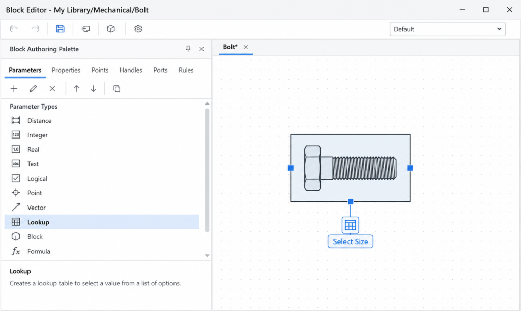
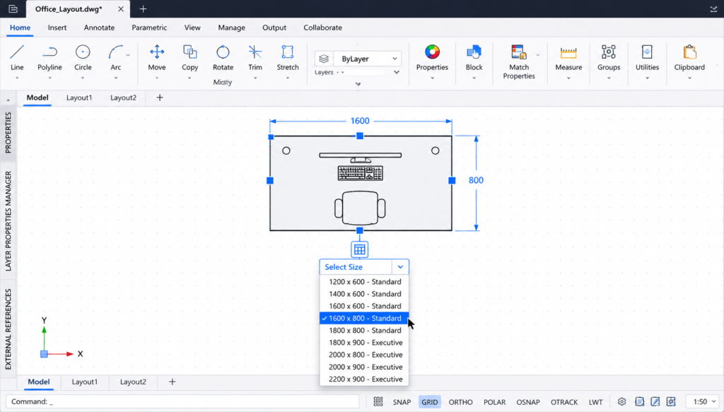
Parametric CAD is not a separate type of CAD so much as a design methodology , the most important methodology in modern engineering CAD. A parametric CAD model encodes the design intent as well as the geometry: relationships between features, governing dimensions, and the logical order in which features are created are all part of the model definition.
The defining characteristic of parametric CAD is that changing a parameter value automatically propagates through the entire model, updating all dependent features according to the design intent encoded when the model was built. A parametric model of a bolt pattern does not just record where the holes are , it records that the holes are equally spaced around a bolt circle of a specified diameter, so changing the bolt circle diameter automatically repositions all holes correctly.
Parametric vs Non-Parametric CAD
| Aspect | Parametric CAD | Non-Parametric (Direct) CAD |
| Change propagation | Changes to parameters automatically update entire model | Changes apply only to the selected geometry; no automatic propagation |
| Design intent storage | Design intent encoded in feature tree and constraints | Geometry only , no stored design intent |
| Edit flexibility | Structured: edits must respect feature dependencies | Flexible: any face or edge can be moved freely |
| Best for | Production design, repeated design iterations, family-of-parts design | Concept modelling, imported geometry repair, quick shape exploration |
| Learning curve | Steeper: must plan feature structure to edit reliably | Faster to start: no upfront structural planning required |
| Major tools | SolidWorks, CATIA, NX, Creo, Inventor | SpaceClaim, Fusion 360 (direct), Creo Flexible Modelling Extension |
Type 4: Direct Modelling (Explicit) CAD
Direct modelling (also called explicit modelling or history-free modelling) is an approach where the engineer manipulates geometry directly , pushing faces, pulling edges, blending surfaces , without a parametric feature history constraining those manipulations. Each edit acts on the current state of the geometry rather than on a record of how it was built.
Direct modelling has two primary use cases: fast concept exploration (where the freedom to modify without feature history constraints accelerates early-stage design) and working with imported geometry (where files from other CAD systems arrive as dumb solids without feature history). Tools like Ansys SpaceClaim (now SpaceClaim Engineer) are specifically optimised for the latter , preparing imported CAD geometry for FEA simulation by simplifying, repairing, and modifying solids that have no parametric history.
Type 5: Surface Modelling CAD
Surface modelling creates 3D shapes as collections of mathematical surfaces rather than as volumetric solids. Where solid modelling is analogous to sculpting a clay block, surface modelling is analogous to bending and joining sheets of material , building the outer skin of an object face by face.
Surface modelling is essential for any design where the precise shape and curvature of the exterior surface is itself the primary design criterion: automotive body panels (where surface curvature affects aerodynamics, water runoff, and visual reflection quality), aircraft fuselage and wing skins (where aerodynamic performance is surface-quality dependent), and premium consumer product casings (where the visual and tactile quality of the surface is a primary differentiator).
NURBS: The Mathematics of CAD Surfaces
Most CAD surface modelling is based on NURBS (Non-Uniform Rational B-Splines) , a mathematical representation that can define smooth curves and surfaces of arbitrary complexity with a compact set of control points and weights. NURBS surfaces can represent everything from a perfect cylinder to a complex organic aerodynamic shape, and they export to neutral formats (IGES, STEP) without losing surface quality.
Class A Surfaces
The highest standard of surface quality in automotive and consumer product design is called Class A surfaces: surfaces that are not just smooth but have mathematically perfect curvature continuity across all joins. Class A is the standard for automotive exterior body panels and is tested by analysing how light and environment reflections behave across the surface , any discontinuity in curvature shows up as a visible distortion in the reflection. CATIA FreeStyle and Autodesk Alias are the primary tools for Class A surface creation.
Type 6: Building Information Modelling (BIM) Software
BIM software represents the application of CAD technology to the architecture, engineering, and construction (AEC) industry, with a fundamental difference from conventional CAD: in BIM, the model is not just a collection of geometric shapes but a database of intelligent building objects , walls, doors, windows, beams, pipes, ducts , each containing geometric, physical, and functional data about the real building element it represents.
A BIM model of a building knows that the object labelled ‘Wall Type A’ is a 200mm thick load-bearing concrete wall with specific thermal properties, fire rating, and finish specifications. When a door is placed in that wall, the BIM software automatically creates the opening in the wall geometry, adjusts the wall area calculations, and records that the wall has a door of a specific type. This intelligence enables automatic generation of schedules, quantity takeoffs, energy analyses, and clash detection reports from a single coordinated model.
BIM Levels of Development
| BIM Level | What It Means | Key Capability Enabled |
| LOD 100 (Conceptual) | Approximate size, shape, location, and orientation | Site planning, massing studies, conceptual energy analysis |
| LOD 200 (Schematic) | Approximate geometry with generic object types, quantities, and systems | Preliminary clash detection, approximate cost estimating, coordination between disciplines |
| LOD 300 (Design Development) | Specific geometry, size, shape, location, orientation with real object types | Detailed clash detection, accurate quantity takeoff, construction coordination, permit drawings |
| LOD 350 (Construction) | Full construction detail with interface information for adjacent elements | Complete construction coordination, fabrication drawings, MEP coordination |
| LOD 400 (Fabrication) | Full fabrication and assembly detail , as-built representation | Off-site fabrication, assembly sequencing, shop drawings |
| LOD 500 (As-Built) | Model verified on-site to actual conditions | Facilities management, maintenance planning, digital twin |
The dominant BIM software tool globally is Autodesk Revit, which holds approximately 60 to 70 percent of the BIM market for architectural and structural design. Graphisoft ArchiCAD is a strong competitor, particularly in Europe. Bentley’s OpenBuildings Designer is used for large infrastructure projects. The open exchange format for BIM data is IFC (Industry Foundation Classes), developed by buildingSMART International, which allows different BIM tools to exchange building model data without proprietary format dependency.
Type 7: CAD/CAM Software , Design to Manufacture
CAD/CAM software (Computer-Aided Design / Computer-Aided Manufacturing) combines 3D design tools with manufacturing programming tools in a single integrated workflow. The “manufacturing” part (CAM) generates the machine instructions , typically CNC toolpaths and G-code , needed to produce the designed component on a CNC milling machine, lathe, router, plasma cutter, or other computer-controlled manufacturing equipment.
The fundamental advantage of an integrated CAD/CAM workflow is that the same geometric model used for design is used directly for manufacturing programming , there is no need to recreate or import geometry into a separate CAM package. Any change to the design model automatically updates the associated toolpaths when the CAM program is regenerated, reducing the risk of manufacturing from outdated geometry.
What CAM Software Does
- Toolpath generation: Calculates the precise path the cutting tool must follow to remove material from a workpiece and produce the designed geometry
- Machine simulation: Simulates the complete cutting process to verify toolpaths, check for collisions between the tool/holder and workpiece/fixture, and estimate machining time
- G-code output: Generates the machine-specific numerical control code (G-code) that is loaded into the CNC machine controller
- Setup documentation: Produces setup sheets describing workholding, tool selection, cutting parameters, and operation sequence for the machinist
The most significant CAD/CAM development for everyday engineers in recent years is Autodesk Fusion 360’s integrated CAD+CAM workflow. Fusion 360 provides fully capable 2.5-axis, 3-axis, 4-axis, and 5-axis milling, turning, and wire EDM programming alongside its 3D design tools in a single subscription at a price accessible to small manufacturers and individual engineers.
Type 8: CAD/CAE Software , Simulation and Analysis
CAD/CAE software (Computer-Aided Engineering) uses the geometry of a CAD model as the input for numerical simulation , predicting how a design will perform under real-world conditions before any physical prototype is built. The economic and safety value of this capability is enormous: finding that a bracket will fail under load in a simulation takes minutes and costs nothing to fix; finding it in a physical test takes weeks and may require costly tooling changes; finding it in service may cost lives.
The Primary Types of CAE Simulation
- Finite Element Analysis (FEA): Predicts structural stress, strain, deflection, and failure in solid components under mechanical, thermal, or dynamic loading. The most widely used simulation type in mechanical engineering.
- Computational Fluid Dynamics (CFD): Simulates fluid flow (liquid or gas) around or through a 3D geometry , predicting aerodynamic drag, lift, pressure drops, heat transfer, and flow distributions.
- Thermal analysis: Predicts temperature distributions through conduction, convection, and radiation , critical for electronics cooling, engine thermal management, and HVAC system design.
- Modal analysis / dynamics: Predicts natural frequencies and vibration mode shapes of structures , essential for avoiding resonance failures.
- Multi-physics simulation: Couples multiple physics domains (structural + thermal + fluid) in a single simulation , used for complex coupled problems like thermal expansion causing structural stress.
The dominant CAE platform globally is ANSYS, which provides FEA, CFD, thermal, electromagnetic, and multi-physics simulation tools. SolidWorks Simulation provides integrated FEA within the SolidWorks environment. COMSOL Multiphysics specialises in coupled multi-physics problems. Autodesk Nastran and MSC Nastran are the aerospace and automotive standard for structural analysis.
The Three Modelling Paradigms: Solid, Surface, and Mesh
Within 3D CAD, three distinct mathematical paradigms are used to represent geometry. Understanding them explains why different CAD tools are used for different types of design work.
| Paradigm | How Geometry Is Represented | Best For | Strengths | Limitations |
| Solid Modelling (B-rep) | Closed volumetric solids defined by bounding surfaces, edges, and vertices | Mechanical engineering, product design, structural components, anything that will be manufactured | Mathematically complete, mass properties calculable, Boolean operations, FEA-ready | Less suited to organic/sculptural shapes; requires watertight geometry |
| Surface Modelling (NURBS) | Collections of smooth mathematical surfaces without enclosing a volume | Automotive styling, aerospace aerodynamics, consumer product aesthetics, complex curved shapes | Perfect curvature control, Class A surfaces achievable, handles organic shapes well | Surfaces must be manually stitched and made watertight for manufacturing |
| Mesh / Polygon Modelling | Geometry approximated by a mesh of flat polygonal faces (triangles or quads) | Game assets, visual rendering, 3D printing of organic shapes, reverse engineering from scan data | Handles highly complex organic shapes, fast for visualisation, compatible with 3D printing | Not dimensionally precise, limited manufacturing suitability, large file sizes for complex models |
Modern professional CAD tools are increasingly hybrid, supporting multiple modelling paradigms within the same environment. SolidWorks supports both solid and surface modelling. CATIA and NX support all three. Fusion 360 integrates solid, surface, and mesh (T-spline) modelling. The ability to move fluidly between paradigms , starting with surface forms, solidifying them for structural analysis, and exporting mesh for visualisation , is increasingly a defining capability of enterprise-class CAD platforms.
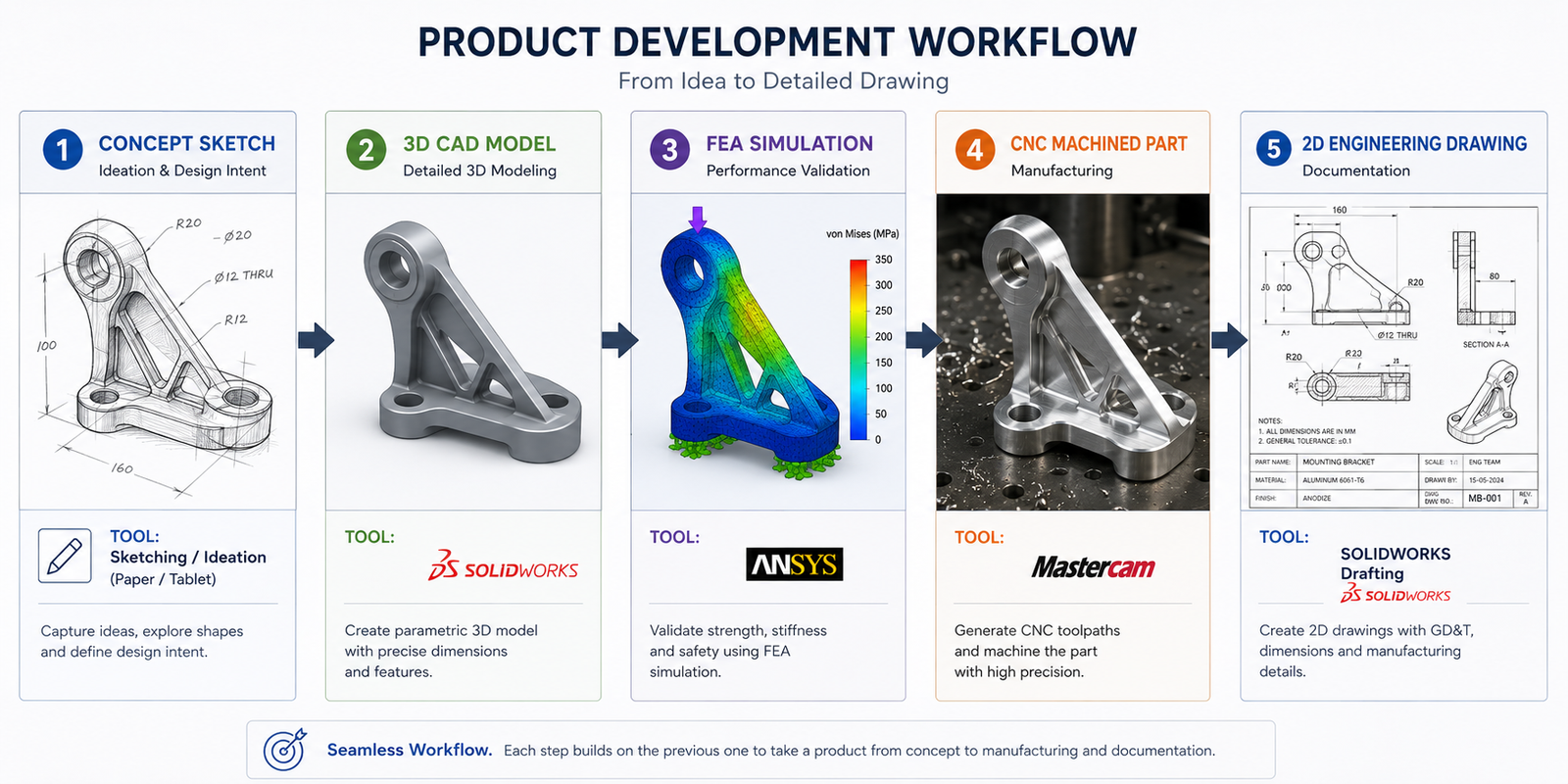
How CAD Fits into the Product Development Workflow
CAD software does not exist in isolation. It sits within a structured product development or construction workflow that defines how design intent is captured, developed, verified, documented, and communicated from initial concept through to finished product or built structure. Understanding where each type of CAD fits in this workflow clarifies why different tools are used at different stages.
| Workflow Stage | Primary Activity | CAD Type Used | Typical Tools | Output |
| Concept and Ideation | Sketching, form exploration, initial proportioning | Direct modelling, sketch tools, mesh modelling | Fusion 360, SketchUp, Shapr3D, Blender | Concept sketches, rough 3D form studies |
| Schematic Design | Establishing spatial layout, system routing, design intent | 2D CAD, BIM, schematic tools | AutoCAD, Revit (BIM), Visio (schematics) | Schematic drawings, layout plans, system diagrams |
| Detail Design | Fully detailed 3D models with all geometry, tolerances, and materials | Parametric 3D CAD, surface CAD (for Class A) | SolidWorks, CATIA, NX, Creo | 3D solid models, assembly models |
| Analysis and Simulation | Verifying structural integrity, fluid performance, thermal behaviour | CAE simulation software | ANSYS, SolidWorks Simulation, COMSOL, Fluent | FEA stress results, CFD flow fields, factor of safety reports |
| Manufacturing Documentation | Creating drawings, specifications, BOM, NC programs | 2D CAD, CAD/CAM | AutoCAD, SolidWorks Drawing, Fusion 360 CAM | Engineering drawings, bills of materials, CNC toolpaths, G-code |
| Fabrication and Construction | Producing the physical object or structure | 2D drawings, CAM G-code, BIM models | Factory equipment, CNC machines, construction site | Physical product or built structure |
| Operations and Maintenance | Managing the built asset throughout its service life | Digital twin, BIM (facilities), PLM | Bentley AssetWise, IBM Maximo, Autodesk Tandem | As-built models, maintenance records, performance data |
CAD File Formats Explained
CAD file formats are one of the most practically important topics for working engineers and designers. The choice of file format for exchanging CAD data between tools, teams, and organisations determines what information is preserved, what is lost, and what compatibility problems will arise.
| Format | Type | What It Preserves | Best Used For | Limitations |
| DWG | Native (Autodesk) | Full 2D drawing content: all AutoCAD objects, layers, styles, blocks, attributes | Sharing between AutoCAD users; universal 2D drawing exchange | Proprietary format with version compatibility issues across AutoCAD versions |
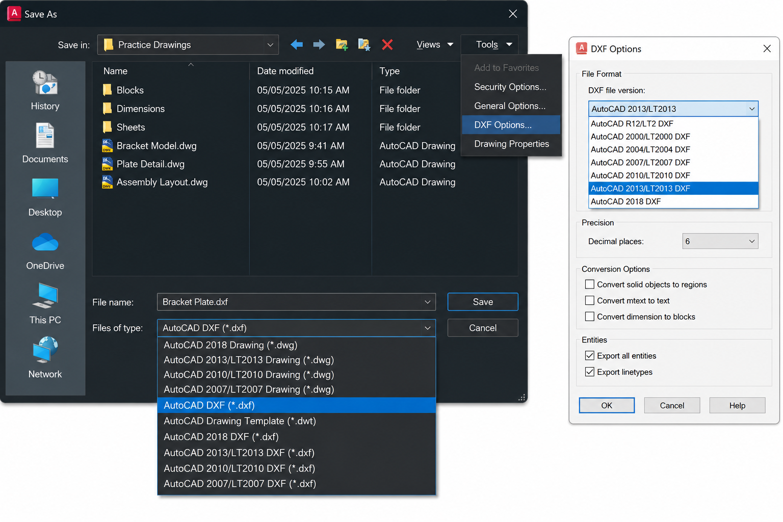
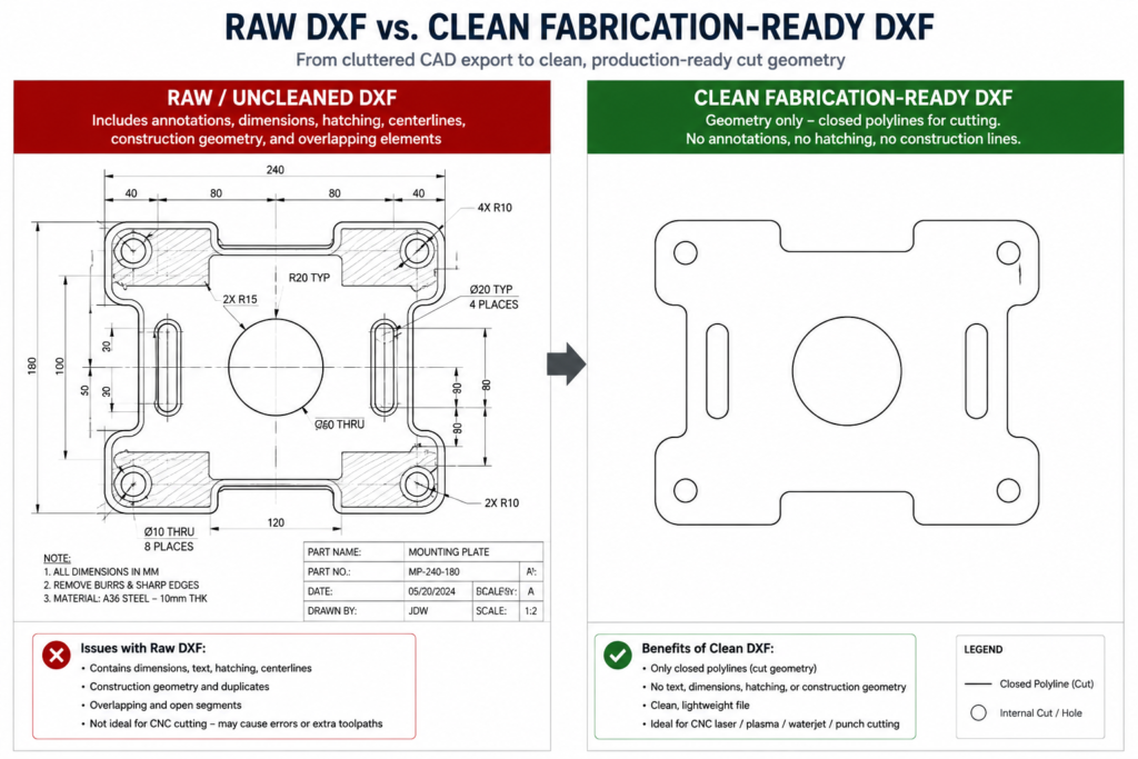
| DXF | Open interchange | 2D geometry, layers, blocks , simplified vs DWG | Sending 2D drawings to non-AutoCAD tools, CNC machines, laser cutters | Complex AutoCAD objects simplified or lost; older versions lose newer features |
| STEP (.stp/.step) | Open 3D neutral | Full solid geometry, B-rep, assembly structure, some metadata | Gold standard for 3D solid model exchange between different CAD tools | Does not preserve parametric history or feature trees |
| IGES (.igs/.iges) | Open 3D neutral (older) | Surfaces, solids (B-rep), some assembly data | Legacy 3D exchange, particularly for surface-heavy aerospace/automotive data | Older standard; STEP is generally preferred for new work |
| STL | 3D printing / mesh | Triangle mesh approximation of 3D surface , no solid data | 3D printing, rapid prototyping, reverse engineering, visualisation | No exact geometry (faceted approximation), no parametric data, no units |
| SLDPRT / SLDASM | Native (SolidWorks) | Full parametric feature history, assembly structure, mates | Working within SolidWorks environment; sharing with other SolidWorks users | Only readable in SolidWorks (or with SolidWorks viewer) |
| IFC | Open BIM | Full BIM model: building objects, geometry, metadata, relationships, schedules | Exchanging BIM models between Revit, ArchiCAD, and other BIM tools | Not all tools implement IFC equally; some data loss common across platforms |
| FBX | Visualisation / animation | Mesh geometry, materials, textures, animation data | 3D rendering, visualisation, game engine import | Not suitable for engineering manufacturing |
| Parasolid (.x_t) | Geometric kernel neutral | Full B-rep solid geometry without feature history | Transferring solid geometry between tools sharing Parasolid kernel | Limited tool support compared to STEP |
| OBJ | Mesh / visualisation | Polygon mesh, materials, texture coordinates | 3D visualisation, rendering, web 3D, game assets | No engineering precision, no solid data, no dimensions |
| File Format Decision Rule: For 3D solid model exchange between different CAD tools: use STEP (.step). It is the most universally supported neutral 3D format and preserves solid geometry with the least data loss. For 2D drawing exchange with non-AutoCAD users or fabrication services: use DXF (R14). For 3D printing: use STL. For BIM model exchange: use IFC. Always keep your native format (.sldprt, .dwg, .rvt) as the master file. |
Desktop CAD vs Cloud-Native CAD: Architecture and Trade-offs
The fundamental architecture of CAD software , whether it runs on a local workstation or lives in the cloud , is one of the most consequential decisions in modern CAD adoption. This is not just a technical question. It affects security, collaboration, hardware cost, IT overhead, and the long-term direction of the engineering workflow.
| Dimension | Desktop CAD | Cloud-Native CAD |
| Data location | Local hard drive or company server | Vendor cloud (AWS, Google, Azure infrastructure) |
| Processing | Local CPU/GPU , performance limited by workstation spec | Hybrid: geometry solving local, storage and collaboration cloud |
| Collaboration | PDM/PLM required (Vault, Teamcenter, Windchill) | Built-in real-time collaboration without PDM infrastructure |
| Version control | Manual (naming conventions) or PDM-managed | Automatic, branching/merging model similar to git |
| Offline working | Full functionality | Reduced , most operations require internet |
| Hardware cost | High-spec workstation required ($2,000-$8,000+) | Any modern computer with web browser |
| IT overhead | Significant , installs, updates, licence servers, PDM admin | Minimal , vendor manages infrastructure |
| Data security / IP | Data under company control | Data on vendor infrastructure , IP risk consideration |
| Large assembly performance | Better , local processing not network-limited | Limited , large assemblies can be slow over network |
| Feature maturity | Most mature , decades of development | Improving rapidly , some gaps vs desktop at extremes |
| Best for | Enterprise engineering, large assemblies, aerospace, automotive, any IP-sensitive sector | Startups, SMEs, remote teams, hardware companies, rapid product development |
The CAD Software Ecosystem: Point Tools vs Integrated Suites
The CAD software ecosystem is structured into three distinct categories that reflect different approaches to the relationship between design, simulation, manufacturing, and data management:
Point Tools
Point tools are software applications designed to do one thing exceptionally well. AutoCAD is a point tool for 2D drafting. ANSYS Fluent is a point tool for CFD. Mastercam is a point tool for CAM. Point tools offer the deepest capability in their specific domain and are often the preferred choice of specialists, but they require file translation workflows when moving data between stages of the development process.
Integrated Suites
Integrated suites combine multiple CAD, simulation, and data management capabilities within a single platform and data model. Siemens NX integrates CAD, CAM, and CAE. Autodesk Fusion 360 integrates CAD, CAM, and simulation. Dassault 3DEXPERIENCE integrates SolidWorks/CATIA, simulation, and PLM. Integrated suites eliminate file translation between stages and ensure that the analysis model is always in sync with the design model, at the cost of less depth in any individual domain compared to the best specialist point tools.
Platform Ecosystems
The largest CAD vendors have evolved from selling software tools to building platform ecosystems that connect CAD tools with PDM, PLM, ERP, simulation, generative design, IoT, and digital twin technologies. Autodesk’s Platform Services (formerly Forge) and Construction Cloud, Dassault’s 3DEXPERIENCE Marketplace, Siemens’ Xcelerator portfolio, and PTC’s ThingWorx IoT + Windchill PLM all represent attempts to expand the value of CAD from a design tool into the connective tissue of the entire product lifecycle.
Best CAD Software by Engineering and Design Discipline
| Discipline | Primary CAD Tool | Alternative / Specialist Tool | Key Reason |
| Mechanical Engineering (Product Design) | SolidWorks | Autodesk Inventor or Fusion 360 | Dominant market share, largest ecosystem, most employer-required parametric 3D tool in mid-market |
| Mechanical Engineering (Enterprise/Aerospace) | CATIA or Siemens NX | PTC Creo | Mandated by major aerospace and automotive OEMs; only tools with the scale for complex programs |
| Civil Engineering | AutoCAD Civil 3D | Bentley MicroStation / OpenRoads | Dominant for road, drainage, and site design; Bentley for large infrastructure networks |
| Architecture (Documentation) | AutoCAD | MicroDraft, VectorWorks | Universal standard for architectural technical drawings and construction documentation |
| Architecture (BIM) | Autodesk Revit | Graphisoft ArchiCAD | Market-leading BIM platform for architectural design and multi-discipline coordination |
| Structural Engineering | AutoCAD | Tekla Structures (structural steel) | AutoCAD for detailing; Tekla for 3D structural steel fabrication modelling |
| Electrical Engineering | AutoCAD Electrical | EPLAN (EDA, not traditional CAD) | AutoCAD Electrical toolset for wiring diagrams; EPLAN for complex panel design |
| Manufacturing / CNC | Fusion 360 (CAD+CAM) | Mastercam, NX CAM | Fusion 360’s integrated CAD+CAM at competitive price; Mastercam for advanced multi-axis |
| Product Design / Industrial Design | Fusion 360 or Rhino 3D | SolidWorks, Alias (styling) | Fusion 360 for functional design; Rhino for complex form; Alias for automotive Class A styling |
| 3D Printing / Additive | Fusion 360 or nTop | SolidWorks, FreeCAD | Fusion 360 has best generative/lattice design for AM; nTop (nTopology) for advanced lattice structures |
AI and the Future of CAD Software
Artificial intelligence is beginning to transform CAD software at a pace that is accelerating in 2024 and 2026. The changes range from incremental productivity improvements to potentially fundamental shifts in how engineering design is done.
Generative Design
Generative design uses AI optimisation algorithms to explore thousands of design configurations based on engineering constraints defined by the engineer: load cases, material constraints, manufacturing method, mass targets, and performance objectives. The resulting geometries are often organic in form , mathematically optimised rather than intuitively designed , and frequently achieve the same structural performance as conventional designs at 20 to 50 percent lower mass.
Autodesk’s generative design tools (in Fusion 360 and Inventor) are the most widely deployed. nTop (nTopology) specialises in lattice and field-driven generative structures for additive manufacturing. SOLIDWORKS AI Topology Study provides topology optimisation within the SolidWorks environment.
AI-Assisted Design Workflows
- SOLIDWORKS Aura (2026): An AI co-pilot embedded in SolidWorks that answers design questions, suggests features, and assists with model creation through conversational interaction.
- Autodesk AI (Fusion 360 / AutoCAD): AI-powered command autocomplete, design suggestions, and automated drawing creation features being rolled out across Autodesk products.
- Physics-Informed Neural Networks (PINNs): Research-stage AI that can solve FEA and CFD problems at speeds orders of magnitude faster than traditional solvers, enabling real-time simulation during design.
- Automated drawing creation: AI tools that automatically generate 2D drawing views, add dimensions, and create title blocks from 3D models, reducing documentation time significantly.
The Long-Term Trajectory
The convergence of AI, generative design, and digital twin technology is moving CAD software toward a future where the engineer’s role shifts from geometry creation toward design intent specification: defining the problem (loads, materials, constraints, cost targets) and evaluating the AI-generated solutions rather than manually creating every geometric feature. This is not imminent for most engineering work , the complexity and safety criticality of most engineered products ensures that human engineering judgement will remain central for decades. But the direction of travel is clear and the pace is accelerating.
CAD Software Career Paths and Certifications
Proficiency in CAD software is not a career in itself , it is a foundational skill that amplifies the value of engineering, architecture, and design expertise. The career paths built on CAD proficiency span roles from CAD technician through to engineering director, and the salary premium for certified CAD proficiency is consistently documented across all major engineering job markets.
| Career Path | Primary CAD Tools | Key Certifications | Typical Entry Salary (US) | Senior Potential |
| Mechanical Design Engineer | SolidWorks or NX/CATIA | CSWP, CSWE (SolidWorks) | $65,000-$80,000 | $110,000-$150,000+ |
| Civil/Infrastructure Engineer | AutoCAD Civil 3D, MicroStation | Autodesk ACP Civil 3D | $60,000-$75,000 | $95,000-$130,000 |
| Structural Engineer | AutoCAD, Tekla, Revit | Autodesk ACP, Tekla certification | $60,000-$72,000 | $90,000-$125,000 |
| Architectural Designer | AutoCAD, Revit | Autodesk ACP AutoCAD/Revit | $55,000-$70,000 | $85,000-$120,000 |
| Manufacturing/CNC Engineer | Fusion 360, Mastercam, NX | Autodesk CAM certification | $60,000-$75,000 | $90,000-$120,000 |
| CAE/Simulation Engineer | ANSYS, SolidWorks Simulation, Abaqus | ANSYS certification programmes | $70,000-$90,000 | $115,000-$155,000 |
| BIM Manager / Coordinator | Revit, Navisworks, Civil 3D | Autodesk Certified Professional (Revit) | $65,000-$80,000 | $95,000-$130,000 |
| Aerospace Structural Engineer | CATIA, NX, ANSYS Nastran | CATIA/NX certificates, PE licence | $80,000-$100,000 | $130,000-$180,000+ |
| Certification Strategy: The highest-return CAD certification investment for most engineers in 2026 is the SOLIDWORKS Certified Professional (CSWP) , independently validated, widely recognised by employers, and consistently associated with 15 to 25 percent salary premiums. For multi-discipline engineers, the Autodesk Certified Professional (ACP) in AutoCAD provides the broadest career coverage. Both can be achieved through self-study and tested at Autodesk/Dassault-authorised testing centres globally. |
Frequently Asked Questions (FAQ)
What is CAD software?
CAD software (Computer-Aided Design software) is a category of computer application used to create, modify, analyse, and document designs of physical objects, structures, and systems with engineering-level precision. It ranges from 2D technical drafting programs (AutoCAD) to 3D parametric solid modelling tools (SolidWorks, CATIA), architectural BIM platforms (Revit), simulation software (ANSYS), and integrated CAD/CAM manufacturing programming systems (Fusion 360). CAD software replaced manual drawing boards across engineering, architecture, and manufacturing, and is used by over 10 million professional engineers, architects, and designers globally.
What are the main types of CAD software?
The eight main types of CAD software are: (1) 2D CAD for technical drawing and documentation (AutoCAD); (2) 3D Solid Modelling CAD for creating volumetric product models (SolidWorks, Inventor); (3) Parametric CAD for intelligent models that update by design intent (SolidWorks, CATIA, NX); (4) Direct Modelling CAD for flexible geometry manipulation without history (SpaceClaim); (5) Surface Modelling CAD for complex curved forms (CATIA FreeStyle, Rhino, Alias); (6) BIM software for intelligent building design (Revit, ArchiCAD); (7) CAD/CAM software for design-to-manufacture (Fusion 360, Mastercam); (8) CAE/Simulation software for design analysis (ANSYS, SolidWorks Simulation).
What is parametric CAD?
Parametric CAD is a 3D CAD approach where the model captures design intent , the relationships, constraints, and governing dimensions that define how the design is meant to work , alongside the geometry. When a parameter is changed (for example, a dimension or a constraint), the entire model updates automatically to reflect the change throughout all dependent features. Parametric CAD tools include SolidWorks, CATIA, Siemens NX, PTC Creo, and Autodesk Inventor. It contrasts with direct modelling, where geometry is manipulated freely without stored parametric history.
What is BIM and how is it different from CAD?
BIM (Building Information Modelling) is a specific type of CAD for the construction industry where the model contains not just geometry but intelligent building objects , walls, doors, beams, pipes , each containing physical, functional, and material data about the real building element they represent. Unlike standard CAD (which produces geometric shapes), BIM models automatically generate schedules, cost estimates, energy analyses, and clash detection reports because the objects are data-rich. The most widely used BIM tool is Autodesk Revit. BIM is a form of CAD, but with intelligence, data, and multi-discipline coordination capabilities that standard CAD tools do not provide.
What is the difference between CAD, CAM, and CAE?
CAD (Computer-Aided Design) creates the 3D model or 2D drawing of the product or structure. CAM (Computer-Aided Manufacturing) uses the CAD model to generate the machine instructions (CNC toolpaths, G-code) needed to manufacture the part on computer-controlled equipment. CAE (Computer-Aided Engineering) uses the CAD model as input for numerical simulation (FEA, CFD, thermal analysis) to verify that the design will perform as required before physical testing. These three disciplines represent the progression from design through analysis to manufacture, and modern integrated tools like Fusion 360 and NX combine all three in a single platform.
What is the best CAD file format for sharing with other software?
The best CAD file format for sharing 3D solid models between different CAD tools is STEP (.step or .stp) , it is an open, internationally standardised format that preserves complete B-rep solid geometry and assembly structure with minimal data loss across all major CAD platforms. For 2D drawing exchange, DXF (R14) is the most widely compatible format, readable by virtually every CAD tool and fabrication system. For 3D printing, use STL. For BIM model exchange, use IFC. Always retain your native format file as the master document.
What CAD software is best for beginners?
The best CAD software for beginners depends on the target discipline. For general engineering and the widest career applicability: AutoCAD (free student licence) for 2D drafting and Fusion 360 (free for students/personal use) for 3D modelling are the most accessible starting points. Both have large communities, abundant tutorials, and free access for learners. For those targeting architecture, Revit’s student version is the appropriate starting tool. For mechanical engineering specifically, SolidWorks student licences provide access to the industry’s most widely used professional tool at low cost.
How is AI changing CAD software?
AI is changing CAD software in several important ways in 2026: Generative design algorithms explore thousands of design configurations based on constraints, producing optimised geometries at lower mass; AI co-pilots (SolidWorks Aura, Autodesk AI) embed conversational AI assistance directly into the design workflow; Physics-Informed Neural Networks are beginning to accelerate FEA and CFD simulation by orders of magnitude; and automated drawing creation tools are reducing documentation time. The long-term trajectory moves the engineer’s role from geometry creation toward design intent specification and AI-generated solution evaluation.
What is the difference between 2D CAD and 3D CAD?
2D CAD produces flat technical drawings on a 2D plane , engineering drawings, floor plans, schematics , that describe an object’s shape through multiple views (front, top, side) and dimensions. It is the direct digital replacement for the drawing board. 3D CAD creates a complete three-dimensional digital model of an object in a 3D coordinate space. The 3D model has volume, mass, and surface area, can be viewed from any angle, can be used for simulation and interference checking, and can automatically generate 2D drawing views. Most modern engineering workflows use 3D CAD for design and 2D CAD drawings for manufacturing documentation.
What is NURBS in CAD?
NURBS (Non-Uniform Rational B-Splines) is the mathematical representation used by most professional CAD tools to define smooth curves and surfaces. NURBS surfaces can describe anything from a simple flat plane to a complex aerodynamic fuselage shape with perfect mathematical continuity. They are defined by control points and weights that determine how the surface is pulled toward each control point. NURBS is the standard representation for surface modelling in tools like CATIA, Rhino, Autodesk Alias, and SolidWorks. The STEP and IGES file formats preserve NURBS surface data for exchange between tools.
Conclusion
CAD software is not a single technology. It is a diverse family of tools, each evolved to address a specific aspect of the design, analysis, documentation, and manufacturing workflow. Understanding the landscape , what each type of CAD is for, how the types relate to each other, how the major tools within each type compare, and how the whole ecosystem fits together , is the foundation for making intelligent decisions about which tools to learn, which to deploy, and which to commission.
The history of CAD is a history of progressive democratisation: from room-sized mainframes accessible only to the largest aerospace corporations in the 1960s, to personal computer tools accessible to any engineering firm by the 1990s, to cloud-native tools accessible to any individual engineer for free today. Each wave of democratisation has expanded the population of people who design and engineer things, and the current wave, AI-assisted generative design and cloud collaboration, will continue that expansion.
For students and early-career engineers, the practical implication is clear: invest in genuine proficiency in the tools that matter for your industry (not the tools with the best marketing), obtain recognised certifications where available, and stay alert to the AI-driven changes that are beginning to reshape what CAD proficiency means in practice. The engineer who can specify design intent, evaluate AI-generated solutions, and communicate effectively with manufacturing and construction teams , amplified by deep CAD toolset knowledge, will be the most valuable engineering professional of the next decade.
Explore the full CAD Software cluster: Best CAD Software for Engineers , our comprehensive tool-by-tool comparison with pricing, industry fit, and career impact. Or begin building your foundational CAD skills with AutoCAD Tutorials for Beginners and Professionals.