Few engineering disciplines can match the career versatility of mechanical engineering. A mechanical engineer can begin their career designing automotive powertrains, spend a decade in oil and gas, transition into renewable energy, consult across multiple industries, and retire as a technical director in medical devices, all with the same foundational degree. No other engineering qualification opens as many doors across as many industries.
The challenge, for students and early-career engineers especially, is navigating that breadth intelligently. With so many mechanical engineering career paths available, and with the profession changing faster than at any point in the past century, making informed decisions about which industry to enter, which specialisation to develop, and how to progress strategically requires reliable, current, and comprehensive information.
This guide provides exactly that. It covers all 12 major industries that employ mechanical engineers, with real salary data from the U.S. Bureau of Labor Statistics (BLS), typical roles, work environments, growth outlook, and major employers. It maps the complete career progression from graduate engineer to engineering director. It compares salaries globally. It explains how to pivot between industries. And it answers the questions engineers actually ask when planning their careers.
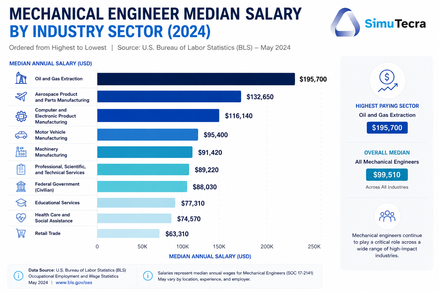
| Key Data Point: According to the U.S. Bureau of Labor Statistics, 293,000+ mechanical engineers are currently employed in the United States. The profession is projected to grow 9 percent from 2024 to 2034 (much faster than average), generating approximately 18,100 new job openings annually. The median annual wage was $102,320 in May 2024, with the top 10 percent earning over $161,240. The highest-paying single industry for mechanical engineers is oil and gas extraction at a median of $195,700 per year. |
Why Mechanical Engineering Career Choice Matters More Than Most Engineers Realise
The industry you enter as a mechanical engineer shapes far more than your immediate salary. It determines the technical problems you work on, the pace of professional development, the stability of your income through economic cycles, the ceiling on your long-term earnings, and even your quality of life outside of work. Industry choice is arguably the single most consequential career decision a mechanical engineer makes, yet it is often made almost casually, based on which company happened to offer an internship or which graduate scheme had the best signing bonus.
The data tells a clear story: median mechanical engineer salaries vary by a factor of nearly two across industries, from around $93,000 to $180,000+ in the US, depending on sector. A mechanical engineer who spends 20 years in a lower-paying sector, even with strong performance and regular promotions, may never reach the starting salary of a counterpart who chose a premium industry from the outset.
At the same time, higher pay is not always the right metric. Some of the highest-paying industries (oil and gas, nuclear) also have the most demanding work environments, the most geographic constraints, and the greatest exposure to commodity price cycles. Some of the most personally rewarding specialisations (medical devices, educational robotics, sustainable engineering) do not top the salary tables. Understanding the full picture, across pay, growth, stability, work environment, and personal fit, is what this guide is designed to provide.
Salary by Industry: The Master Table Every ME Should Study
The following table presents mechanical engineer salary data by industry sourced from the U.S. Bureau of Labor Statistics (BLS) Occupational Employment and Wage Statistics survey, May 2024. This is the most authoritative and comprehensive salary dataset available for the US engineering job market.
| Industry Sector | Median Annual Wage (US, 2024) | Employment Level | 10-Year Growth Outlook | Entry-Level Salary Range |
| Oil and Gas Extraction | $195,700 | ~4,800 MEs | Moderate; offset by energy transition risk | $85,000 – $105,000 |
| Solar Electric Power Generation | $167,170 | Growing rapidly | Very strong through 2035 | $72,000 – $90,000 |
| Natural Gas Distribution | $145,920 | Stable | Moderate; transitioning to hydrogen | $75,000 – $92,000 |
| Nuclear Electric Power Generation | $137,810 | Stable to growing (new reactor programmes) | Strong with nuclear renaissance | $78,000 – $95,000 |
| Semiconductor and Electronic Components | $107,890 | ~14,000+ MEs | Strong: CHIPS Act investment driving growth | $75,000 – $92,000 |
| Transportation Equipment Manufacturing | $103,210 | ~29,000 MEs | Strong; EV transition reshaping roles | $68,000 – $82,000 |
| Aerospace and Defence | $100,000 – $115,000* | ~50,000+ MEs | Steady; commercial space driving new demand | $70,000 – $85,000 |
| Architecture, Engineering Services | $102,990 | ~52,000 MEs (largest single employer) | Strong; multi-industry consulting growth | $65,000 – $80,000 |
| Medical Devices and Instruments | $95,000 – $110,000* | ~20,000 MEs | Very strong; ageing population and robotics | $68,000 – $82,000 |
| Machinery Manufacturing | $96,690 | ~41,000 MEs | Steady; automation integration driving change | $62,000 – $76,000 |
| HVAC and Building Services | $85,000 – $98,000* | ~15,000 MEs | Strong; net-zero building requirements | $58,000 – $72,000 |
| Robotics and Automation OEMs | $95,000 – $115,000* | Rapidly growing | Very strong; fastest growing sector | $68,000 – $82,000 |
*Ranges marked with asterisk are estimated from BLS industry-adjacent codes and ASME salary survey data where specific BLS codes do not precisely match these sectors. All other figures are BLS OEWS May 2024 data for SOC 17-2141 (Mechanical Engineers).
| Important Context: US salary data does not translate directly to other markets. A mechanical engineer earning $103,000 in the US might earn GBP 55,000 in the UK, EUR 75,000 in Germany, or AUD 110,000 in Australia. Each market has different cost-of-living profiles, tax structures, and industry concentrations. The international comparison section later in this article covers these differences in detail. |
Industry 1: Automotive Engineering
The automotive industry is one of the largest and most historically prominent employers of mechanical engineers, and it is currently in the middle of its most significant transformation since the invention of the internal combustion engine. Automotive mechanical engineering is simultaneously losing traditional ICE roles and creating new ones in EV powertrain, battery thermal management, lightweighting, and autonomous systems engineering at a rate that is reshaping the entire talent landscape.
What Automotive MEs Work On
- Powertrain engineering: Engine and transmission design (ICE), electric motor and inverter integration, hybrid system development
- Chassis and suspension: Structural design, ride and handling optimisation, NVH (noise, vibration, harshness) analysis
- Battery thermal management: Cooling system design for lithium-ion and solid-state battery packs
- Lightweighting: Advanced aluminium alloys, carbon fibre composites, topology-optimised structures to offset EV battery mass
- Safety and crashworthiness: FEA-based crash simulation, regulatory homologation (NCAP, FMVSS)
Work Environment and Culture
Automotive engineering ranges from fast-paced, competitive OEM environments (Ford, GM, Stellantis, Toyota, BMW, Volkswagen) to Tier 1 supplier roles (Bosch, Continental, Aptiv, BorgWarner) and fast-growing EV startups (Tesla, Rivian, Lucid, NIO). OEM roles tend to offer structured development programs, defined processes, and exposure to complex multi-disciplinary projects. Startup automotive roles offer more autonomy, faster learning, and equity upside at higher personal risk.
By 2030, 40 percent of automotive engineering jobs are projected to require expertise in EV powertrains and AI-driven diagnostics according to industry analysis. Engineers who understand both mechanical fundamentals and battery electrochemistry basics, thermal management, and electric motor integration are in the strongest position.
Industry 2: Aerospace and Defence
Aerospace engineering is widely regarded as the most technically demanding and professionally prestigious application of mechanical engineering. It consistently ranks among the highest-paying industries for mechanical engineers and offers exposure to the most rigorous structural analysis, thermal engineering, and precision manufacturing challenges in the profession.
What Aerospace MEs Work On
- Structural analysis: FEA-based stress and fatigue analysis of airframes, wings, and pressure vessels to meet FAA/EASA airworthiness standards
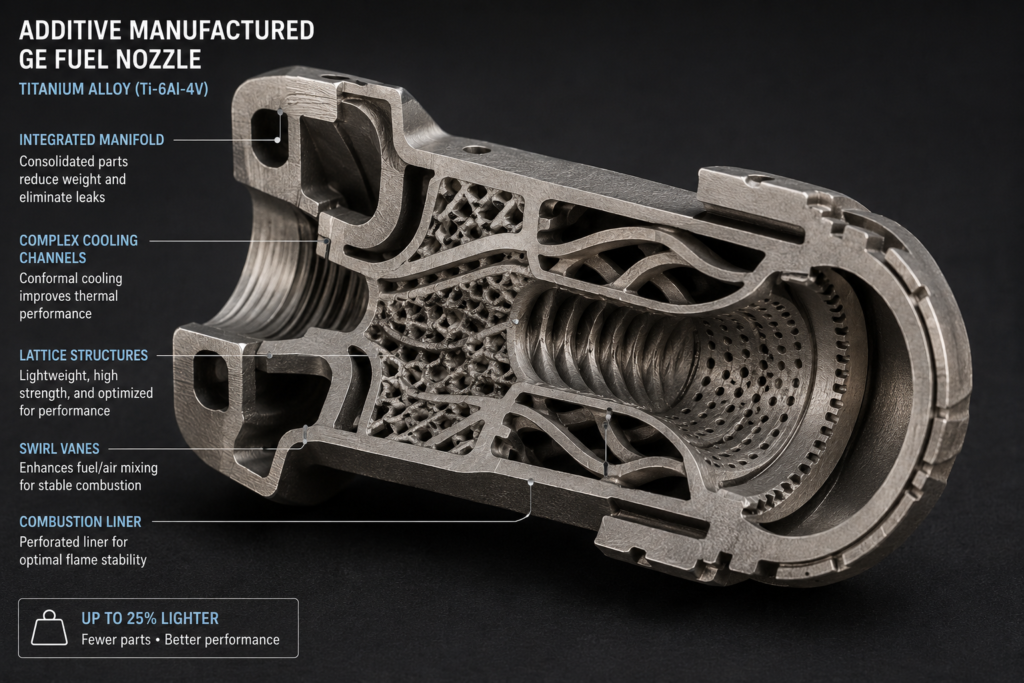
- Propulsion systems: Gas turbine component design, combustor development, turbine blade cooling, additive manufactured engine parts
- Thermal management: Aircraft environmental control systems, avionics cooling, re-entry thermal protection systems for space vehicles
- Mechanisms and actuation: Landing gear, flight control surfaces, cargo handling systems, docking mechanisms for space vehicles
- Reusable launch vehicles: Structural design, propellant system engineering, thermal protection, and landing system design for commercial space
Key Employers and Locations
Major aerospace employers include Boeing, Airbus, Lockheed Martin, Northrop Grumman, Raytheon, BAE Systems, Rolls-Royce, GE Aerospace, Safran, SpaceX, Blue Origin, and hundreds of Tier 1 and Tier 2 suppliers. Geographic concentrations in the US include Seattle, Southern California, Houston, and Huntsville. In Europe, Toulouse, Hamburg, Bristol, and Munich are primary aerospace hubs.
The commercial space sector, valued at approximately $630 billion in 2024, is creating a new category of aerospace mechanical engineering jobs focused on reusable rockets, satellite constellations, and in-orbit servicing, areas with significant demand for engineers who combine structural and thermal expertise with an appetite for rapid development cycles.
Industry 3: Energy (Oil, Gas, and Renewables)
The energy sector is the single highest-paying industry for mechanical engineers in the US and one of the most rapidly transforming. Oil and gas extraction pays a median of $195,700 for MEs, while solar electric power generation pays a median of $167,170. Both figures significantly exceed the all-industry ME median of $102,320, reflecting the technical complexity, physical remoteness, and high-consequence nature of energy engineering work.
Oil and Gas: Still the Highest Payer
Mechanical engineers in oil and gas work on drilling systems, wellhead equipment, pipeline integrity, compression and processing facilities, and offshore platform structures. The premium pay reflects demanding work environments (offshore rotation, remote onshore facilities), high safety requirements, and the commercial value of engineering decisions in an industry measured in billions of dollars. Required expertise includes ASME pressure vessel codes, API standards, corrosion engineering, and rotating equipment design. Engineers considering this path should weigh the premium pay against long-term career risk as the energy transition progresses.
Renewables: The Fastest Growing Energy Sector
The renewable energy sector employed mechanical engineers at 35 percent of its total workforce according to 2026 industry data, with solar alone supporting approximately 263,000 engineering jobs in the US. Mechanical engineers in renewables work on wind turbine structural design and drivetrain engineering, solar tracker mechanisms and mounting system structures, offshore wind foundation design, energy storage thermal management, and hydrogen production and storage systems. Federal clean energy investment is driving sustained and rapidly growing demand, with the IEA projecting renewable energy investment to reach $1.74 trillion in 2026.
Industry 4: Manufacturing and Industrial Automation
Manufacturing employs more mechanical engineers than any other single sector, accounting for approximately 50 percent of all ME employment in the US according to the BLS. Within manufacturing, machinery manufacturing alone employs 41,000 mechanical engineers and transportation equipment manufacturing employs a further 29,000. Industrial automation, driven by the reshoring of manufacturing to the US and Europe and by Industry 4.0 investment, is one of the fastest-growing sub-sectors.
What Manufacturing MEs Work On
- Process engineering: Designing and optimising production processes, selecting and specifying manufacturing equipment, implementing lean manufacturing
- Tooling and fixture design: CNC machining fixtures, press tools, injection moulding tools, assembly jigs
- Quality engineering: Statistical process control, measurement system analysis, GD&T, coordinate measuring machine (CMM) programming
- Automation integration: Robotic cell design, cobot integration, conveyor and handling system engineering
- DFM/DFA consultation: Reviewing designs from product development for manufacturability and assembly efficiency
The manufacturing industry is projected to have 2.1 million unfilled jobs by 2030 due to a skills gap, according to Deloitte and the Manufacturing Institute. Mechanical engineers with automation and robotics integration skills are particularly scarce and command premiums of 10 to 20 percent above conventional manufacturing ME roles.
Industry 5: Medical Devices and Biomedical Engineering
The medical device industry is one of the most technically demanding and personally rewarding sectors for mechanical engineers. Products must meet the same level of structural and functional reliability as aerospace components, operate in the most hostile chemical environment possible (the human body), navigate complex regulatory pathways including FDA 510(k) and PMA submissions in the US and CE marking in Europe, and often be designed to the smallest possible size and mass.
What Medical Device MEs Work On
- Implantable device design: Orthopaedic implants, cardiovascular devices (stents, heart valves, pacemaker housings), spinal implants
- Surgical instrument and robot design: Laparoscopic tools, surgical robot mechanisms, robotic actuator systems (da Vinci, Medtronic Hugo)
- Diagnostic equipment: MRI bore structures, CT gantry mechanisms, ultrasound transducer housings
- Wearable and ingestible devices: Drug delivery systems, continuous monitoring devices, remote patient monitoring hardware
- Verification and validation (V&V): Mechanical testing to FDA standards, fatigue life testing, accelerated aging
Major employers include Medtronic, Boston Scientific, Abbott, Stryker, Zimmer Biomet, BD (Becton Dickinson), Intuitive Surgical, Edwards Lifesciences, and Philips Healthcare. Geographic hubs include the Minneapolis-St Paul medical device corridor, Boston’s Route 128 corridor, and the San Francisco Bay Area. Knowledge of FDA Design Controls (21 CFR Part 820) and ISO 13485 quality management is essentially mandatory for experienced roles in this sector and adds a meaningful salary premium.
Industry 6: Robotics and Advanced Automation
Robotics is the fastest-growing employer of mechanical engineers globally, driven by the convergence of falling component costs, expanding AI capabilities, and mounting demand for automation in logistics, healthcare, agriculture, and construction. The global industrial robotics market reached $48 billion in 2024 and is projected to exceed $100 billion by 2030 according to the International Federation of Robotics (IFR).
What Robotics MEs Work On
- Robot structural design: Frame and link design for articulated, SCARA, delta, and collaborative robots
- Actuator and joint engineering: Harmonic drives, torque sensors, cable-driven mechanisms, soft pneumatic actuators
- End effector design: Grippers, tool changers, welding torches, dispensing heads
- AMR design: Autonomous mobile robot chassis, wheel modules, suspension systems, LiDAR mounting structures
- Mechanism design: Four-bar linkages, cam mechanisms, compliant mechanisms for precision motion
The World Economic Forum’s Future of Jobs Report 2026 identified robotics, automation, and mechatronics as the most important knowledge areas for manufacturing sector engineers over the next 10 years. Mechanical engineers with Python programming skills alongside mechanical design expertise command salary premiums of 15 to 25 percent.
Industry 7: HVAC and Building Services Engineering
Heating, Ventilation, and Air Conditioning (HVAC) engineering applies thermodynamics and fluid mechanics to control the thermal environment of buildings, data centres, hospitals, industrial facilities, and transportation systems. Given that buildings account for approximately 40 percent of global energy consumption, HVAC engineers are at the front line of the global decarbonisation effort.
HVAC roles generally offer some of the best work-life balance in mechanical engineering: work is predominantly office-based, projects follow predictable cycles, and demand is stable across economic cycles because buildings always require thermal management. Salary is below the top-paying industries but competitive, and demand is being boosted by net-zero building regulations that are requiring significant HVAC system upgrades across existing building stock globally.
Key employers include major MEP (Mechanical, Electrical, Plumbing) consultancies including Arup, WSP, Jacobs, AECOM, Atkins, and Thornton Tomasetti, alongside equipment manufacturers including Carrier, Trane, Daikin, Johnson Controls, and Honeywell.
Industry 8: Semiconductor and Electronics Manufacturing Equipment
The semiconductor equipment industry is one of the most technically demanding and financially rewarding sectors for mechanical engineers, yet it is significantly under-represented in conventional career guidance resources. Mechanical engineers in this sector design the precision machines that make chips: photolithography systems, CVD reactors, ion implant equipment, wafer handling robots, and CMP tools. These are arguably the most precision-demanding mechanical systems built in any industry.
Major employers include ASML, Applied Materials, Lam Research, KLA Corporation, and Tokyo Electron. The US CHIPS and Science Act, signed in 2022, committed $52 billion to domestic semiconductor manufacturing expansion, driving sustained demand for mechanical engineers in semiconductor equipment design and process engineering. Median ME salary in this sector is $107,890 (BLS May 2024), one of the highest across all manufacturing sub-sectors.
Industry 9: Consumer Products and Durable Goods
Consumer products engineering offers mechanical engineers broad design experience, fast development cycles, and the visible satisfaction of seeing their work on store shelves and in people’s homes. Companies including Dyson, Whirlpool, Black and Decker, Apple, Samsung, and dozens of smaller consumer product companies employ large numbers of mechanical engineers in product development, industrial design support, and manufacturing engineering roles.
The work combines structural analysis (drop testing, durability), thermal management (electronics cooling), DFM optimisation, and supply chain engineering. Salaries in consumer products tend to sit in the mid-range compared to industrial and energy sectors, but the work environment, pace of development, and breadth of exposure make it an excellent launching pad for engineers early in their careers.
Industry 10: Defence and Government Research
Defence engineering offers mechanical engineers some of the most technically challenging and financially rewarding work in the profession, alongside the highest level of employment security available in any engineering sector. Defence budgets tend to be counter-cyclical: they increase or remain stable during economic downturns when private sector engineering contracts contract.
Key areas include weapons systems structural design, armour and ballistic protection engineering, submarine pressure hull design, missile and rocket propulsion, unmanned vehicle systems, and directed energy weapon thermal management. Security clearances are typically required for classified work, which creates a significant barrier to entry but also a meaningful salary premium and reduced competition. Major employers include Lockheed Martin, Northrop Grumman, Raytheon Technologies (RTX), BAE Systems, L3 Harris, DARPA, and national laboratories including Sandia and Los Alamos.
Industry 11: Marine and Offshore Engineering
Marine and offshore engineering applies mechanical engineering to ships, submarines, offshore oil and gas platforms, floating production facilities, and the rapidly expanding offshore wind sector. It is one of the most specialised mechanical engineering disciplines, combining structural analysis for a fatigue environment (constant wave loading), corrosion management in saline environments, propulsion system design, and the engineering of systems that must operate without maintenance for extended periods in remote locations.
The growth of offshore wind energy is creating significant new demand for marine mechanical engineers with expertise in floating foundation design, mooring systems, marine corrosion protection, and subsea cable management. The global offshore wind market is projected to grow from $57 billion in 2023 to over $150 billion by 2030.
Industry 12: Consulting Engineering
Engineering consulting is the most versatile career path in mechanical engineering: consulting engineers are paid for their specialised technical knowledge and apply it across multiple clients, industries, and projects simultaneously. Engineering services is the single largest employer of mechanical engineers in the US by sector, employing over 52,000 MEs at a median salary of $102,990.
Consulting can take several forms: large multi-discipline consultancies (Arup, Jacobs, AECOM, Mott MacDonald), specialist boutique firms focusing on a specific technical area (FEA simulation, tribology, forensic engineering), and independent sole-trader consultants. The consulting career path rewards depth of specialist knowledge, excellent communication skills, and the ability to build and maintain client relationships. Senior consulting engineers can command very high day rates and have significant control over their working patterns.
Career Progression Roadmap: Graduate Engineer to Director
Understanding the typical mechanical engineering career progression at each stage helps engineers set realistic expectations, identify what they need to develop, and make strategic decisions about when and how to advance.
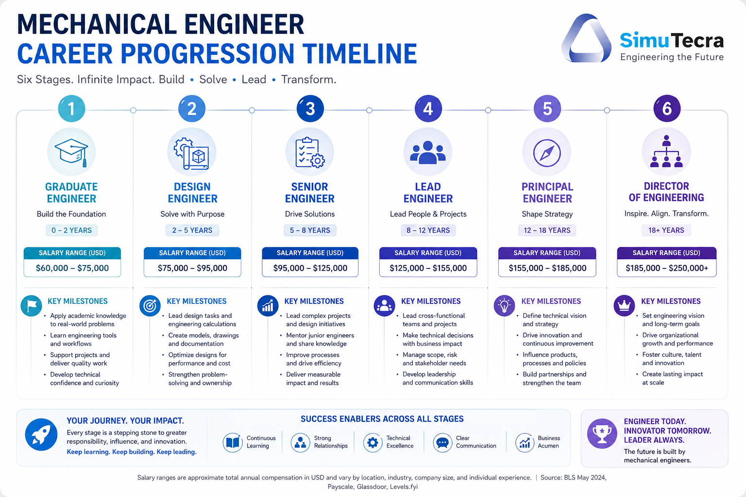
| Career Stage | Years Experience | Typical Titles | Key Responsibilities | Typical US Salary Range | What Drives Progression |
| Graduate / Entry-Level | 0-3 years | Graduate Engineer, Junior ME, Engineer I | CAD modelling, analysis tasks directed by seniors, documentation, test support | $65,000 – $82,000 | Technical depth, initiative, asking smart questions, building foundational skills |
| Mid-Level Engineer | 3-8 years | Mechanical Engineer, Engineer II/III, Design Engineer | Owning subsystems, running analysis independently, leading design reviews, mentoring juniors | $82,000 – $110,000 | Independent judgement, communication, cross-functional leadership, specialisation depth |
| Senior Engineer | 8-15 years | Senior ME, Principal Engineer, Lead Engineer | Technical ownership of programs, setting design standards, customer/executive interaction, complex problem-solving | $110,000 – $140,000 | Technical reputation, mentoring effectiveness, business awareness, breadth of impact |
| Staff / Principal Engineer | 12-20 years | Staff Engineer, Distinguished Engineer, Technical Fellow | Defining technology direction, cross-organisation influence, patents and publications, strategic R&D input | $130,000 – $170,000 | Recognised expertise, thought leadership, internal and external reputation |
| Engineering Management | 10+ years | Engineering Manager, Director of Engineering, VP Engineering | Team leadership, budget management, program oversight, talent development, strategic planning | $130,000 – $200,000+ | People skills, business acumen, strategic thinking, successful team delivery |
| Executive / Director Level | 15-25+ years | Chief Engineer, CTO, VP/SVP Engineering, Engineering Director | Technology strategy, organisational leadership, stakeholder management, P&L responsibility | $180,000 – $300,000+ | Track record of delivery, executive presence, industry network, strategic vision |
| Career Strategy Insight: The most powerful career accelerator in mechanical engineering is developing a reputation as the person who solves problems that others cannot. Early in a career, this means going deep on a technical specialisation while maintaining broad fundamentals. From mid-career onward, it means adding cross-functional leadership, business awareness, and communication skills to that technical foundation. Engineers who remain purely technical specialists throughout their careers can still reach excellent compensation at the Staff/Principal level. Engineers who combine technical depth with leadership capability have the highest career ceiling. |
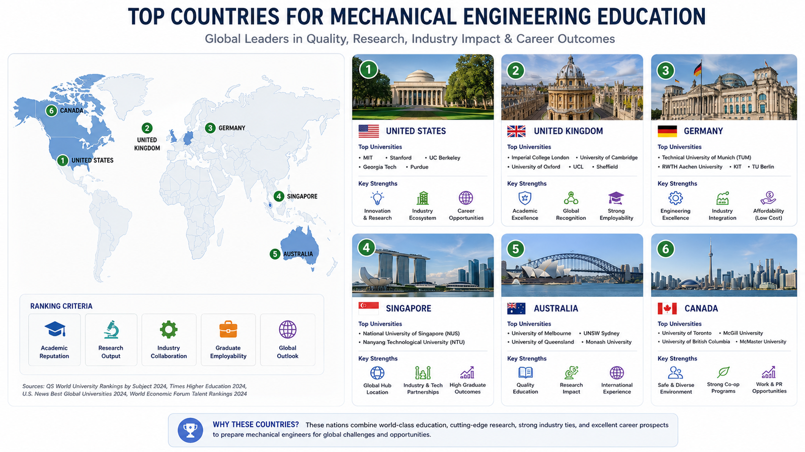
International Salary Comparison: US, UK, Germany, Australia, and Singapore
For engineers considering international careers or comparing offers across markets, the following table provides a realistic comparison of mechanical engineer salaries by country at different career stages. All figures are approximate annual gross salaries in local currency and approximate USD equivalent.
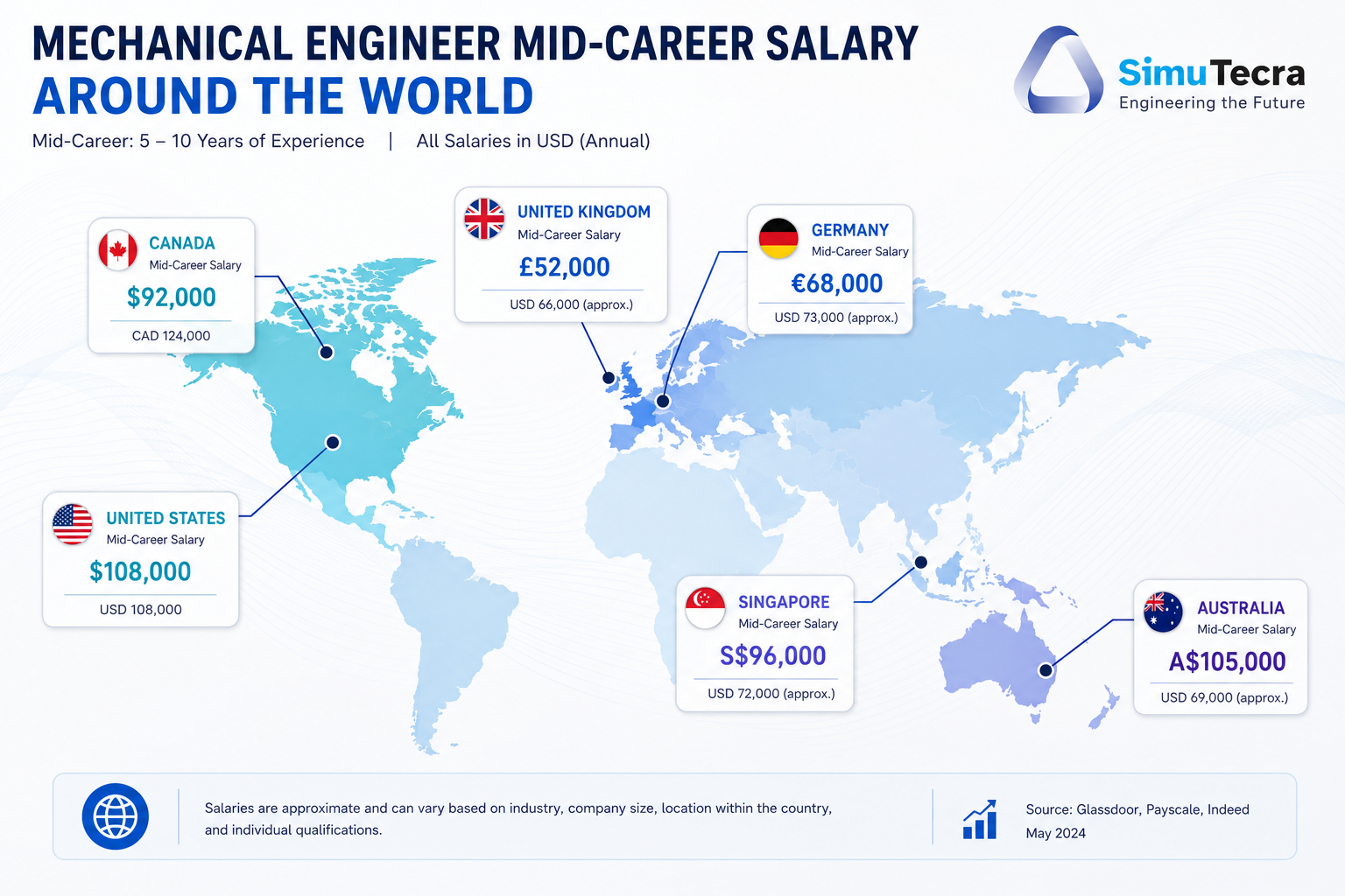
| Country | Entry Level (0-3 yrs) | Mid-Level (3-8 yrs) | Senior (8-15 yrs) | Highest-Paying Industry in Country |
| United States | $65,000 – $82,000 | $82,000 – $110,000 | $110,000 – $155,000 | Oil and gas ($195,700 median BLS 2024) |
| United Kingdom | GBP 28,000 – 36,000 (~$35-45k) | GBP 42,000 – 62,000 (~$53-78k) | GBP 65,000 – 90,000 (~$82-113k) | Aerospace and defence; oil and gas North Sea |
| Germany | EUR 45,000 – 58,000 (~$49-63k) | EUR 62,000 – 82,000 (~$68-90k) | EUR 82,000 – 115,000 (~$90-126k) | Automotive (BMW, Volkswagen, Mercedes-Benz); aerospace |
| Australia | AUD 65,000 – 82,000 (~$42-53k) | AUD 90,000 – 120,000 (~$58-78k) | AUD 120,000 – 165,000 (~$78-107k) | Mining and resources; defence |
| Singapore | SGD 48,000 – 62,000 (~$36-46k) | SGD 70,000 – 100,000 (~$52-74k) | SGD 100,000 – 145,000 (~$74-107k) | Semiconductor equipment; aerospace MRO |
| Canada | CAD 65,000 – 80,000 (~$48-59k) | CAD 85,000 – 115,000 (~$63-85k) | CAD 115,000 – 155,000 (~$85-115k) | Oil sands (Alberta); aerospace (Bombardier, Pratt & Whitney Canada) |
USD equivalents are approximate based on exchange rates as of early 2026 and are provided for comparison purposes only. Purchasing power parity differs significantly between countries. Germany and Australia offer particularly strong value when cost of living is factored in.
Mechanical Engineering Career Pivots: How to Switch Industries
One of the most underappreciated advantages of a mechanical engineering career is the ability to pivot between industries. Because the underlying technical foundations (mechanics, thermodynamics, FEA, fluid mechanics, materials) are universal, a mechanical engineer can move between sectors more readily than most other engineering disciplines. However, successful pivots require understanding what transfers and what needs to be learned.
| From Industry | To Industry | What Transfers Directly | What You Need to Learn | Typical Timeline to Full Competence |
| Automotive | Aerospace | FEA, CAD, structural analysis, DFM, fatigue analysis | FAA/EASA airworthiness standards, aerospace material specifications (AMS), safety case methodology | 12-24 months with target employer training |
| Oil and Gas | Renewable Energy | Pressure system design, rotating equipment, fluid mechanics, ASME codes | Wind turbine structural specifics or solar tracker mechanisms; IEC wind energy standards | 6-18 months; certification courses available |
| Manufacturing | Robotics and Automation | Process knowledge, fixture design, quality engineering, DFM | Robot kinematics, ROS basics, cobot programming, motion control systems | 12-18 months; supplement with online courses and personal projects |
| Any Industry | Medical Devices | Mechanical design, FEA, precision manufacturing | FDA design controls (21 CFR 820), ISO 13485, verification and validation methodology, biocompatibility basics | 18-24 months; specific V&V experience critical |
| Engineering | Consulting | All technical skills from previous industry | Client management, proposal writing, multi-project juggling, commercial awareness, billing practices | Immediate on technical content; 2-3 years to build client relationships |
Certifications and Professional Development That Accelerate Careers
Professional certifications and development activities that genuinely add career value in mechanical engineering fall into three categories: professional licensure, technical software certifications, and specialist knowledge qualifications.
Professional Licensure
- Professional Engineer (PE) License (US): Required for engineering work that affects public safety in infrastructure, government, and consulting roles. Pass FE exam, gain 4 years’ supervised experience, pass PE exam. Adds $10,000 to $20,000 to annual salary on average.
- Chartered Engineer (CEng) Status (UK): The UK benchmark for senior engineering professionals. Awarded by IMechE on demonstration of competency and experience. Required for many senior roles in UK industry and opens doors internationally via IPEA mutual recognition.
- Professional Engineer (P.Eng.) (Canada): Required to practise engineering independently in Canada. Province-regulated; requires accredited degree plus 48 months’ supervised work experience.
Technical Software Certifications
- SOLIDWORKS Certified Professional (CSWP) and Expert (CSWE): Widely recognised in product development and manufacturing. Validates proficiency in SOLIDWORKS 3D modelling and simulation. Entry-level engineers benefit most.
- ANSYS Certifications: ANSYS offers certifications in Mechanical (FEA), Fluent (CFD), and other modules. Recognised by aerospace, automotive, and energy employers.
- Autodesk Certified Professional (AutoCAD, Fusion 360): Valuable for drafting-heavy roles in manufacturing, construction, and consulting.
Specialist Knowledge Qualifications
- Certified Manufacturing Engineer (CMfgE): Awarded by SME (Society of Manufacturing Engineers). Validates manufacturing process knowledge for senior manufacturing ME roles.
- Six Sigma Black Belt (SSBB): Valuable for manufacturing and quality engineering roles. Demonstrates advanced statistical process improvement expertise. Recognised across all manufacturing-heavy industries.
- Project Management Professional (PMP): Not technically specific but adds significant value for engineers moving into project or program management. Recognised across all industries.
- ISO 13485 Lead Auditor: Specific to medical devices but adds meaningful salary premium in that sector. Combined with FDA design controls training, it significantly strengthens medical device career progression.
Read related blog on Frontiers of Mechanical Engineering
Frequently Asked Questions (FAQ)
What industries do mechanical engineers work in?
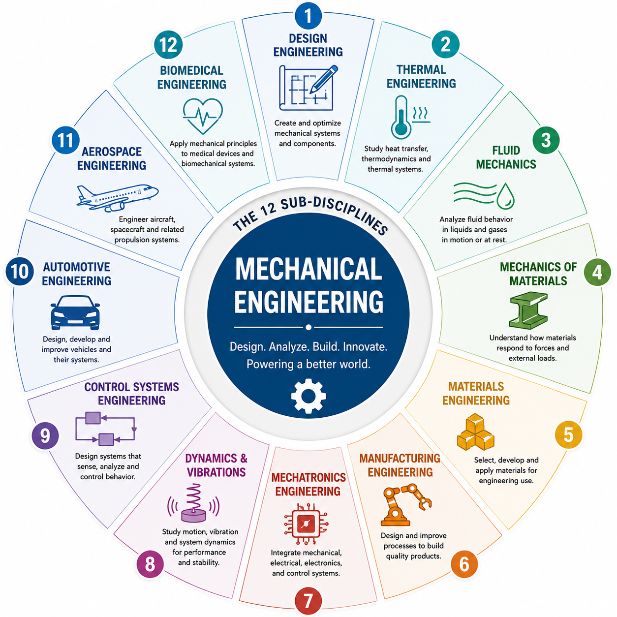
Mechanical engineers work across virtually every industry that involves physical systems and products. The 12 major industries employing the most mechanical engineers are: automotive, aerospace and defence, energy (oil, gas, and renewables), manufacturing and industrial automation, medical devices, robotics and automation, HVAC and building services, semiconductor equipment, consumer products, defence and government research, marine and offshore, and consulting engineering. Manufacturing is the largest employer overall, accounting for around 50 percent of total ME employment, while oil and gas pays the highest median salary.
What is the highest-paying industry for mechanical engineers?
According to the U.S. Bureau of Labor Statistics (BLS) May 2024 data, the highest-paying industry for mechanical engineers is oil and gas extraction, with a median annual wage of $195,700. Rounding out the top five highest-paying industries are solar electric power generation ($167,170), natural gas distribution ($145,920), nuclear electric power generation ($137,810), and semiconductor and electronic product manufacturing ($107,890). These premiums reflect technical complexity, physical demands, and high-consequence operating environments.
What is a good career path for a mechanical engineer?
A good mechanical engineering career path combines strong foundational education with deliberate industry choice, early specialisation in a high-growth area, and progressive development of leadership and communication skills alongside technical depth. The typical progression runs from graduate engineer through mid-level, senior, and principal engineer to engineering management or technical director. The most financially rewarding and professionally fulfilling paths tend to involve entering a high-growth sector (renewable energy, medical devices, robotics, aerospace), developing genuine specialist depth, and adding cross-functional leadership capability from mid-career onward.
Is mechanical engineering a good career in 2026?
Yes, mechanical engineering is an excellent career in 2026 and beyond. The U.S. Bureau of Labor Statistics projects 9 percent job growth from 2024 to 2034, much faster than average, with approximately 18,100 new openings annually. The median salary of $102,320 is more than double the national median for all occupations. The World Economic Forum’s Future of Jobs Report 2026 identified environmental and renewable energy engineering, electrotechnology, and automation, all falling within the mechanical engineering umbrella, as the fastest-growing engineering subfields. The combination of strong demand, high pay, and broad industry applicability makes it one of the most resilient career choices available.
Can mechanical engineers switch industries?
Yes, mechanical engineers can and regularly do switch industries, making it one of the most portable engineering qualifications. The foundational skills (FEA, CAD, thermodynamics, fluid mechanics, materials science) transfer across industries with varying levels of supplementary learning required. The most common successful pivots are from automotive to aerospace, oil and gas to renewables, manufacturing to robotics, and any industry to medical devices (which requires learning FDA regulatory knowledge) or consulting (which requires developing client management skills). Most successful pivots take 12 to 24 months to achieve full competence in the new sector.
How much do mechanical engineers earn globally?
Mechanical engineer salaries vary significantly by country. In the US, the median is $102,320 (BLS 2024). In the UK, mid-career salaries range from GBP 42,000 to GBP 62,000. In Germany, mid-career ranges from EUR 62,000 to EUR 82,000. Australian mid-career ranges are AUD 90,000 to AUD 120,000. Singapore mid-career ranges from SGD 70,000 to SGD 100,000. Germany stands out for exceptional purchasing power: near-zero public university tuition, lower cost of living than equivalent UK and US cities, and strong salaries from world-class engineering employers including BMW, Volkswagen, Siemens, and Bosch.
What certifications help mechanical engineers advance their careers?
The certifications most reliably associated with salary increases and career advancement in mechanical engineering are: Professional Engineer (PE) license in the US (adds $10,000 to $20,000 to annual salary on average), Chartered Engineer (CEng) in the UK (required for senior roles in many sectors), SOLIDWORKS Certified Professional (CSWP) for product development roles, ANSYS certifications for analysis-heavy roles, Six Sigma Black Belt for manufacturing engineering, and ISO 13485 Lead Auditor for medical devices careers.
What are the fastest-growing sectors for mechanical engineering jobs?
The fastest-growing sectors for mechanical engineering employment in 2026 are renewable energy (solar and wind), robotics and automation, electric vehicle engineering, and medical devices. Renewable energy alone employs approximately 35 percent of its workforce in ME roles, with solar supporting 263,000 engineering jobs in the US. Industrial robotics is projected to double its market size to $100 billion by 2030. EV engineering is transforming automotive, with 40 percent of automotive jobs projected to require EV expertise by 2030. Medical devices benefit from ageing population demographics and surgical robotics adoption.
Conclusion
Mechanical engineering offers one of the most genuinely versatile career landscapes of any profession. The same foundational knowledge that allows an engineer to design automotive suspension systems also enables them to analyse offshore pipeline fatigue, optimise wind turbine drivetrains, develop surgical robot mechanisms, and lead engineering teams through industrial transformation programs.
The data is clear and compelling: mechanical engineering careers are growing faster than average, paying significantly above the national median, and expanding into new sectors at a rate that creates continuous new opportunities for engineers at every career stage. The profession’s combination of problem-solving depth, practical impact, and career mobility is not matched by many other fields.
What this guide has attempted to provide is not just the data, but the context to interpret it: understanding why industry choice is so consequential, what the work actually looks like in each sector, where the premium salaries come from, how careers progress at each stage, and what levers engineers have at their disposal to shape their own trajectory.
The engineers who build the most rewarding careers are those who approach their mechanical engineering career with the same analytical rigour they apply to engineering problems: gathering the best available information, identifying the key variables, evaluating the options systematically, and making deliberate decisions rather than drifting. This guide is the information foundation for that approach.
Continue building your knowledge. Read What Is Mechanical Engineering? for the foundational context, explore What Does a Mechanical Engineer Do? for the daily reality of the profession, and discover the Latest Advances in Mechanical Engineering to understand where the most exciting new opportunities are emerging.