The machinist had machined the part correctly. The inspector had measured it correctly. The design engineer had drawn it correctly. The part still failed incoming inspection at the customer’s facility, which didn’t accept the supplier’s inspection report because their measurements showed a different result. Four weeks of back-and-forth followed: measurement reports, photos, calls across three time zones, and finally a re-inspection visit where everyone sat down together and found the answer.
The drawing specified the hole position from the “left edge” of the part. The machinist had measured from the left face, excluding a small chamfer. The inspector had measured from the left edge including the chamfer. The customer had measured from what they considered the left datum, the mating surface of the assembly. Three different interpretations of two words: “left edge.”
| Quick answer: Geometric Dimensioning and Tolerancing (GD&T) exists to solve exactly this problem. It replaces ambiguous phrases like “left edge” with a datum symbol, a feature control frame, and standardised symbols from ASME Y14.5 or ISO 1101 that mean exactly one thing to everyone trained to read them, in any country, in any language. The dimensions weren’t wrong and the machining wasn’t inaccurate; three experienced professionals just interpreted two words three defensible ways, and GD&T eliminates that gap entirely. |
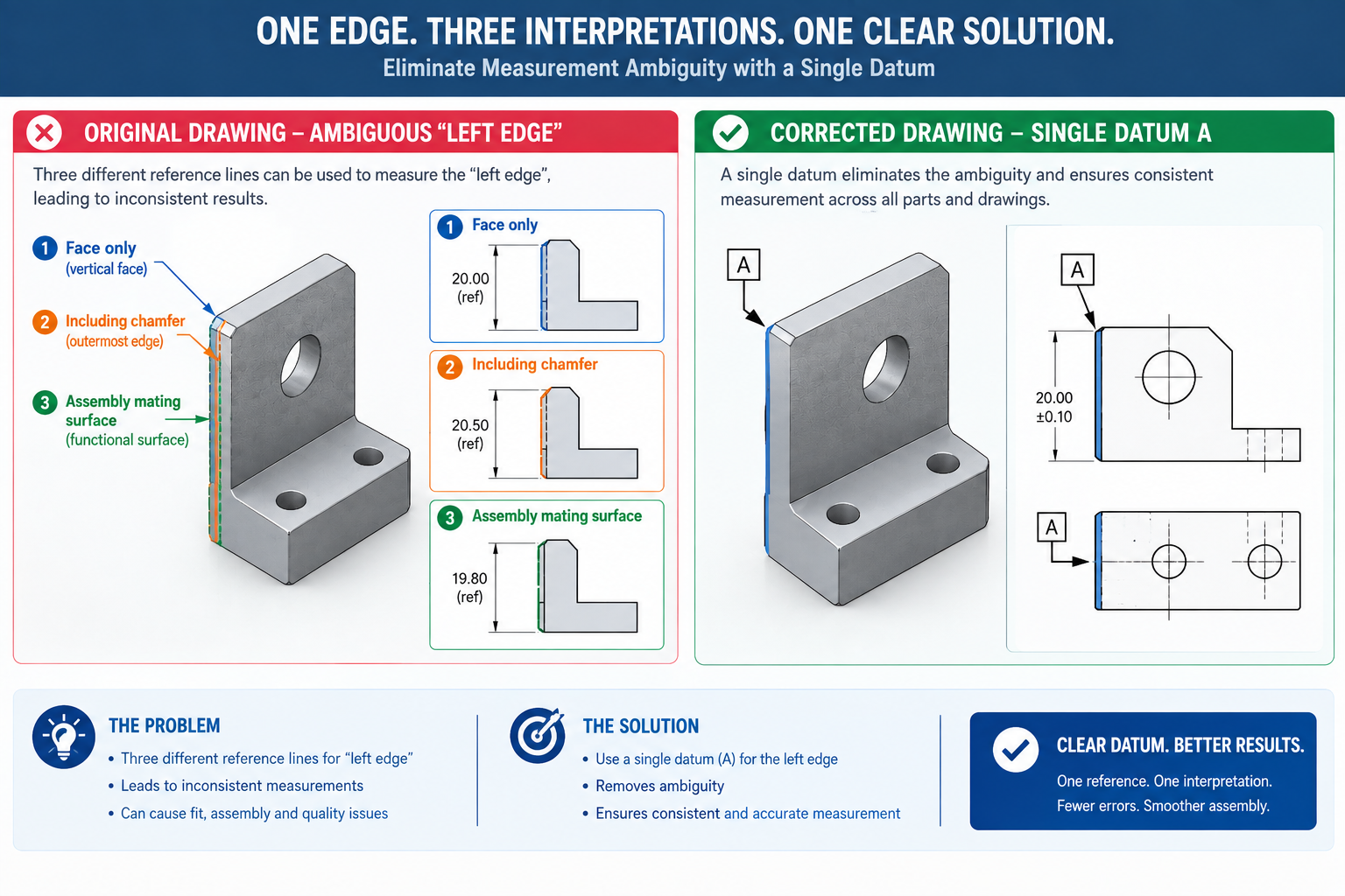
This article isn’t a complete GD&T textbook. It’s a practical guide to how GD&T works as a communication tool: the symbol reference covering all fourteen characteristics, the datum selection guide, position tolerance compared against plus-minus coordinates, and worked examples showing what changes on a drawing and what that means for the machinist, inspector, and supplier.
What GD&T Actually Is and What Problem It Solves
GD&T is a system of symbols and rules describing the allowable variation in the form, orientation, location, and runout of geometric features on a part. It’s defined by ASME Y14.5 in the United States and ISO 1101 internationally, with the two standards broadly similar in philosophy and substantially compatible in practice. The system replaces or supplements traditional plus-minus coordinate tolerancing, using standardised symbols and feature control frames that carry a complete, unambiguous specification in a compact visual form.
The problem GD&T solves isn’t just about symbols. It’s about the gap between what a drawing says and what different people understand it to mean. Plus-minus tolerancing specifies a feature’s location by distance from an implied reference. When that reference is clearly defined and everyone measures it the same way, plus-minus works fine. When the reference is ambiguous, or the machinist, inspector, and customer all use slightly different references, the same physical measurement produces different results. GD&T eliminates this by requiring explicit datum definitions, using a three-datum reference frame that specifies the complete geometric relationship between the controlled feature and the references used to measure it.
The Feature Control Frame: Where All the Information Lives
The feature control frame is the core element of GD&T on a drawing: a rectangular box read left to right, containing the geometric characteristic symbol, the tolerance value, and one to three datum references. Combined, this contains a complete, self-contained geometric specification that needs no additional note to be unambiguous.
A feature control frame reading position, 0.15, diameter symbol, datum A, datum B translates to: “the centre of this hole must be within a cylindrical tolerance zone of 0.15mm diameter, oriented perpendicular to datum A and located by true position relative to datums A and B.” Every word of that sentence lives inside the frame, and once you can read the symbols, you can read every feature control frame on every drawing following ASME Y14.5 or ISO 1101.
The 14 GD&T Characteristics: What Each One Controls
GD&T defines fourteen geometric characteristics across five categories: form (four, no datum required), orientation (three, datum required), location (three, datum required), runout (two, datum required), and profile (two, datum optional).
| Category | Characteristic | What It Controls | Datum Required? | Most Common Application |
|---|---|---|---|---|
| Form | Straightness | How straight an axis or surface line element must be | No | Cylindrical shaft axis; long narrow flat surfaces |
| Form | Flatness | How flat a surface must be; deviation from a perfect plane | No | Sealing surfaces, mating datum faces, PCB mounting pads |
| Form | Circularity | How round a single cross-section must be | No | Sealing bores, bearing seats, rotating surfaces |
| Form | Cylindricity | How close to a perfect cylinder the full surface is | No | Precision bearing bores, hydraulic cylinder bores |
| Orientation | Perpendicularity | How close to 90° a surface/axis is relative to a datum | Yes | Boss faces, shaft axes, mating flange faces |
| Orientation | Angularity | How close to a specified angle relative to a datum | Yes | Angled faces, tapered holes, dovetail slides |
| Orientation | Parallelism | How parallel a surface/axis is to a datum | Yes | Parallel rails, clamp/vice jaw faces, slide guides |
| Location | Position | How far a feature may be from its true theoretical location | Yes | Hole patterns, boss positions; replaces plus-minus for holes |
| Location | Concentricity | How close median points are to a datum axis | Yes | Often replaced by runout or position for practical inspection |
| Location | Symmetry | How close a median plane is to a datum median plane | Yes | Often replaced by position in modern practice |
| Runout | Circular Runout | Variation in a single cross-section as the part rotates | Yes | Rotating shafts, impeller faces |
| Runout | Total Runout | Variation across the entire surface as the part rotates | Yes | Precision rotating parts, cam surfaces |
| Profile | Profile of a Line | Variation of each line element from a true profile | Optional | Curved surfaces, aerofoil profiles |
| Profile | Profile of a Surface | Variation of the entire 3D surface from a true profile | Optional | Complex freeform surfaces, cast/forged parts, stamped panels |
The Four Most Used Characteristics in Practice
Four characteristics account for the large majority of GD&T callouts on real drawings:
Position controls where a feature is located relative to datums, using basic dimensions (boxed, theoretically exact values with no individual tolerance) to define the true position. It’s the most powerful single GD&T tool for hole patterns and boss locations.
Flatness controls how flat a surface is, independent of any datum, the right tool for sealing faces and mounting bases where overall planarity matters independently of position.
Perpendicularity controls how close a surface or axis is to 90 degrees relative to a datum, catching tilt that plus-minus height tolerances miss entirely.
Position with MMC (bonus tolerance) combines position tolerance with the maximum material condition modifier, letting the tolerance zone grow when the feature is produced smaller than its maximum material size. A hole at the upper limit of its diameter tolerance can sit in a less precise position than one at the lower limit, since the larger hole provides more fastener clearance.
Datums: The Foundation That Everything Else Is Measured From
Datums are the most important and most frequently misunderstood element of GD&T. Tolerance values attract most of the attention, but they’re only meaningful relative to the datums they reference. A perpendicularity of 0.05mm to datum A is precise if datum A is a well-defined, stable reference surface, and meaningless if datum A is an ambiguous edge different people measure differently. Getting datum selection right matters more than getting the tolerance numbers right.
| Datum Type | What It Represents | Common Mistake | How to Check It’s Right |
|---|---|---|---|
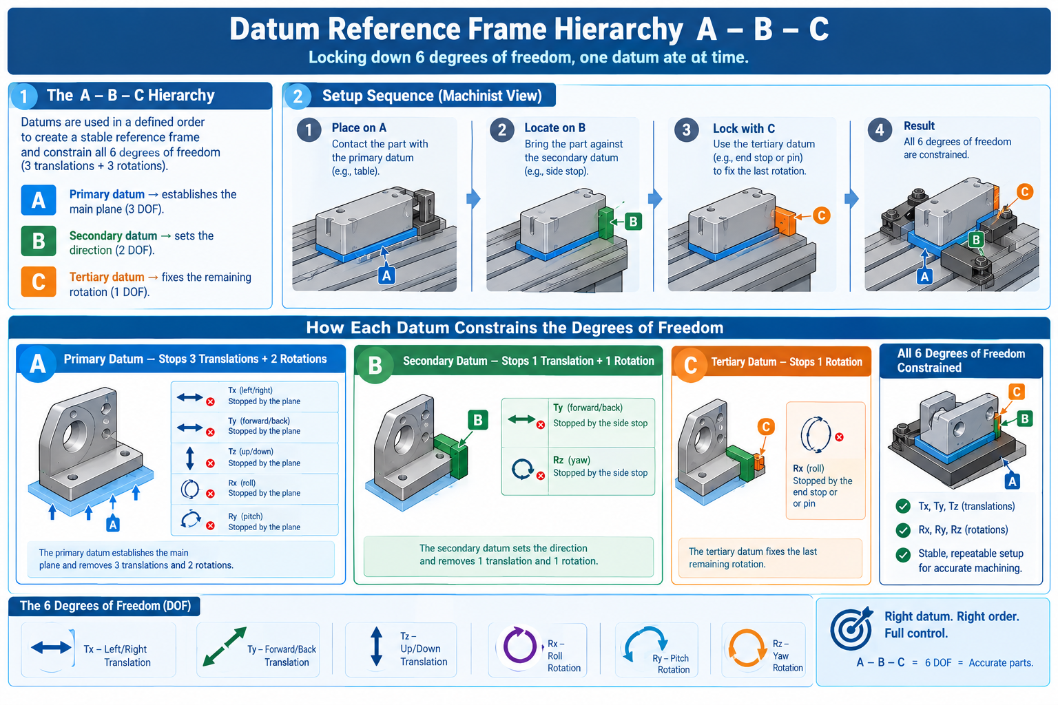
| Primary (A) | The most stable reference surface; constrains 3 degrees of freedom | Choosing a small or convenient CAD surface instead of the actual functional one | Would this part sit stably and repeatably resting on datum A alone? |
| Secondary (B) | Constrains 2 more degrees of freedom; stops translation and rotation | Choosing a secondary parallel to the primary, which gives no independent constraint | Visualise the part on A; datum B should stop the direction it can still slide |
| Tertiary (C) | Constrains the final degree of freedom | Choosing a tertiary too close to the secondary for practical measurement | Should be as far as practical from the secondary for stability |
| Datum feature simulator | The physical surface (granite plate, mandrel) representing the datum in inspection | Assuming a worn or damaged part surface faithfully represents the datum | Inspect the datum surface’s own form before using it to measure others |
| Axis datum | The axis of a cylindrical feature used as a datum | Using a cylindrical datum with significant form error without specifying its own tolerance | Verify roundness and cylindricity of the datum bore/shaft first |
The Functional Datum Principle: Match Datums to How the Part Is Used
The most important principle in datum selection is choosing datums that reflect how the part is actually located in assembly and used in service, not datums that are convenient to measure or match the CAD coordinate system. A part sitting on a flat base in service should use that base as its primary datum. A part located by a precision bore in assembly should use that bore as its primary datum axis. The inspection setup should mirror the assembly setup as closely as possible.
When datums are chosen for convenience rather than function, parts can pass inspection and still fail assembly, one of the most frustrating quality failures in manufacturing, because every individual measurement report shows conforming dimensions and the failure only shows up at the assembly line. This is why datum selection belongs to the design engineer, not the inspection department.
Position Tolerance vs. Plus-Minus: Why the Difference Matters
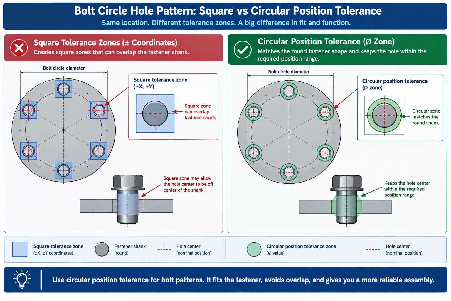
Plus-minus coordinate tolerancing is what most engineers learn first, and it’s adequate for a large fraction of dimensions on a typical drawing. But for mating features, particularly hole patterns where multiple features must collectively locate a mating component, it has a well-documented problem: it creates square tolerance zones where circular zones would better match the physical assembly constraint.
The Square Zone Problem
A hole position specified as 25.00 +/-0.10 in X and 20.00 +/-0.10 in Y creates a square tolerance zone with 0.2mm sides. A hole accepted at the extreme corner, +0.10 in both X and Y simultaneously, sits at sqrt(0.10² + 0.10²) = 0.141mm from true position, forty-one percent further than either coordinate limit alone suggests. For a round fastener hole, a round zone more accurately represents what actually matters: distance from true position in any direction, not deviation in each coordinate separately.
GD&T position tolerance specifies the hole location as a diameter of allowable deviation. A position tolerance of 0.2mm diameter means the hole centre must sit within a 0.2mm diameter circle around true position, a maximum deviation of 0.1mm in any direction, exactly matching what a round fastener clearance requires. This circular zone gives 57 percent more usable area than plus-minus of 0.1mm in each coordinate for the same functional clearance.
| Situation | Plus-Minus Approach | GD&T Position Approach | Why GD&T Is Better |
|---|---|---|---|
| Bolt circle (four holes) | X/Y coordinates each +/-0.1mm; square zone per hole | Single position callout, circular zone diameter, referenced to datum | Square zone accepts diagonal positions a round fastener would reject; 57% more usable tolerance area |
| Perpendicularity of a boss | Height dimension only; no angularity control | Perpendicularity callout controlling the axis to a cylindrical zone relative to datum | Plus-minus height doesn’t catch a boss within height tolerance but tilted 2°, which fails assembly |
| Flatness of a sealing face | General tolerance or surface finish note only | Flatness callout specifying max deviation from a perfect plane | A surface can pass individual point tolerances and still be bowed enough to prevent sealing |
| Slot position relative to a hole | Slot dimensioned from hole centre with plus-minus | Position callout with datum established by the hole; bonus tolerance applies under MMC | Bonus tolerance gives more slot position tolerance exactly when the locating hole has the most clearance |
| Runout of a rotating shaft shoulder | Diameter plus-minus; concentricity uncontrolled | Circular runout referencing the shaft’s datum axis | A shoulder can pass diameter tolerance while significantly eccentric, causing vibration |
Bonus Tolerance and MMC: When the Tolerance Gets Larger
The maximum material condition (MMC) modifier, a circled M after the tolerance value, formally captures something every experienced assembly engineer knows intuitively: a bigger hole leaves more room for the fastener and doesn’t need to be as precisely located to still work.
MMC for a hole is its minimum diameter, the condition where the material is at maximum. At MMC, the position tolerance applies exactly as specified. As the hole is produced larger, the position tolerance zone grows by the same amount, this additional allowance is bonus tolerance.
Worked example: M6 fastener clearance hole
Specified: 6.5mm diameter, +0.2/-0.0 (range 6.5 to 6.7mm)
Position tolerance: 0.15mm diameter at MMC

At 6.5mm (MMC): position tolerance = 0.15mm diameter
At 6.6mm (0.1mm over MMC): 0.15 + 0.10 = 0.25mm diameter
At 6.7mm (0.2mm over MMC, maximum): 0.15 + 0.20 = 0.35mm diameter
The larger the hole, the more position variation is acceptable, since functional clearance for the fastener increases with hole size. Traditional plus-minus couldn’t capture this without specifying separate position tolerances for different diameter ranges, which nobody does in practice. MMC captures it automatically in a single feature control frame that the machinist, inspector, and customer can all compute and verify identically.
GD&T as Communication: Five Scenarios Where It Resolves Disputes
| Scenario | Without GD&T | With GD&T | Miscommunication Resolved |
|---|---|---|---|
| Hole position dispute | “25.00 +/-0.10 from left edge”; different edges measured differently; dispute begins | Position 0.20mm diameter zone from datum A, B; everyone measures the same reference | The datum removes the “which edge” question entirely |
| Supplier interpreting perpendicularity | “Perpendicular within 0.05mm”; supplier asks over what length, to which surface; days of delay | Perpendicularity 0.05mm cylindrical zone to datum A; complete answer in the symbol | The feature control frame answers length, reference, and geometry without a phone call |
| Inspector accepting/rejecting a part | Each coordinate individually within limits but combined deviation is unclear; judgement call | Position tolerance gives a single diameter comparison against measured deviation; clear pass/fail | GD&T removes the grey zone where parts pass each coordinate but fail combined deviation |
| Planning a machining sequence | Dimensions from different references; machinist guesses which surface to cut first | Clear datum hierarchy A-B-C tells the machinist the foundation surface to cut first | The datum hierarchy expresses the designer’s intended machining sequence directly |
| Cross-border supplier, first drawing | Company-specific shorthand and language-specific notes generate eight clarification calls | Standard ASME Y14.5 symbols readable by any trained engineer, any country | GD&T’s symbol language needs no translation or clarification |
The Cross-Border Supplier Scenario
International supply chains are where GD&T’s role as a universal language matters most. A drawing with text notes in English, company-specific abbreviations, and implied references understood within one engineering team isn’t self-contained once it travels to a supplier who speaks a different first language and works within a different drawing tradition. A drawing using GD&T consistently, with every geometric requirement in feature control frames referencing defined datums, is readable by anyone trained in ASME Y14.5 or ISO 1101 regardless of native language. A well-written GD&T drawing is its own translator.
Common GD&T Mistakes That Undermine Communication
Specifying a GD&T tolerance without the required datum. Position, perpendicularity, angularity, and all orientation and location characteristics require a datum reference to be meaningful. A position callout without a datum defines the tolerance zone’s size but not its location in space, forcing the machinist to guess, recreating the exact ambiguity GD&T exists to prevent. Every location or orientation feature control frame needs at least one datum reference.
Applying GD&T to features that don’t need it. Every feature control frame adds reading complexity, requiring the reader to identify the characteristic, tolerance, and datums and understand how they combine. For features where a simple plus-minus dimension is adequate and unambiguous, like the overall length of a non-mating handle, adding a profile callout adds complexity without adding information. Reserve GD&T for features where its specific capabilities, circular zones, datum-referenced orientation, flatness independent of position, add something plus-minus can’t provide.
Choosing datums that don’t match the assembly setup. A datum scheme using the most convenient measurement surfaces rather than the surfaces that actually locate the part in assembly produces parts that pass inspection and fail assembly. This failure is invisible at the symbol level, the drawing can be technically correct in its GD&T application and functionally wrong in its datum structure, since the technical correctness shows in the drawing and the functional incorrectness only shows up when assembly fails.
Worked Examples
The bolt circle that failed assembly: A machined aluminium flange had eight M8 clearance holes on a 120mm pitch circle, specified by X-Y coordinates with plus-minus 0.15mm each direction. The mating flange used the same approach. Parts passed incoming inspection individually, but assembly consistently produced one misaligned hole pair requiring bolts to be forced or holes filed open.
The square tolerance zones allowed holes up to 0.212mm from their true circular positions. Two holes on opposite flanges, each at the maximally misaligned corner but in different directions, combined for up to 0.424mm misalignment, which the M8 clearance hole’s 0.5mm total clearance couldn’t reliably absorb.
Redesigning with a true position tolerance of 0.20mm diameter at MMC, referenced to the flange face and central bore, replaced the coordinate approach with a polar position control tied to the flange’s actual locating features. Maximum deviation of any hole from true position dropped to 0.10mm, and MMC allowed additional tolerance when holes were larger than minimum size. Combined maximum misalignment between matching holes dropped to 0.20mm, comfortably within the 0.5mm clearance. Assembly interference issues were eliminated, and the drawing got simpler: one basic radius, one basic angular spacing, and one feature control frame replaced sixteen coordinate dimensions.
The supplier dispute that never happened: A design team releasing a machined bracket to an overseas supplier for the first time had previously spent three weeks resolving a dispute with a different supplier over a “top face” reference for mounting hole positions, resulting in batch rejection and rework.
For the new release, the largest mounting face became datum A with a flatness callout of 0.03mm, the perpendicular face became datum B with a perpendicularity callout of 0.05mm to A, and the mounting holes carried position tolerance of 0.15mm diameter at MMC referenced to A and B, with basic dimensions defining their theoretically exact positions. The new supplier machined a first article within the stated lead time, referencing the same datums as the drawing, with no questions about “top face” since datum A was explicit. The first article was accepted on first inspection with zero dispute calls.
Frequently Asked Questions
Do I need to use GD&T on all dimensions, or just some? GD&T is most valuable on dimensions controlling mating features: hole positions for bolt circles and locating pins, surface flatness for sealing and mounting faces, perpendicularity for assembled flanges, and runout for rotating surfaces. Non-mating dimensions with no geometric locating function are adequately controlled by plus-minus with a clear general tolerance note. Over-applying GD&T to every dimension adds drawing complexity without adding communication quality.
What is the most important GD&T characteristic to understand first? Position tolerance, since understanding it requires understanding three things underpinning all of GD&T: basic dimensions, datum reference frames, and the difference between a circular and square tolerance zone. Once position is clear, perpendicularity, angularity, and parallelism are straightforward extensions of the same logic. Flatness is easiest to understand on its own since it needs no datum, but it’s less central to the broader framework than position.
What is bonus tolerance and when does it apply? Bonus tolerance is additional position tolerance available when a feature is produced at a size other than its maximum material condition. For a hole, MMC is the minimum diameter; producing it larger grows the position tolerance zone by the same amount, reflecting that a larger hole can sit in a less precise location and still assemble correctly. Bonus tolerance only applies when the MMC modifier appears in the feature control frame; without it, position tolerance stays fixed regardless of actual feature size.
Why does GD&T use basic dimensions instead of normal toleranced dimensions? Basic dimensions are theoretically exact nominal values carrying no individual tolerance, because the feature’s allowable variation is carried entirely by the feature control frame. If basic dimensions had their own tolerances, the actual allowable variation would combine two separate tolerances with ambiguity about which governs. Basic dimensions remove that: the true position is exactly what the dimension says, and the feature control frame states how far the actual feature may deviate.
How do I choose between profile of a surface and other characteristics for a complex shape? Profile of a surface is the most versatile characteristic, controlling form, orientation, and location simultaneously. For simple flat, cylindrical, or spherical surfaces, a specific form, orientation, or location characteristic is usually clearer and easier to inspect. For complex freeform surfaces, cast housings, aerofoil sections, stamped panels, profile of a surface is often the only practical way to specify the requirement, since no simpler characteristic captures the 3D variation.
Can GD&T be applied to 3D models instead of 2D drawings? Yes, increasingly common through Model-Based Definition (MBD). GD&T annotations attach directly to 3D CAD model features using the same feature control frame symbology and datum structure as a 2D drawing, creating a single authoritative source for geometry and tolerances. ASME Y14.41 defines the standard for digital product definition, and most major CAD packages support MBD annotation. The underlying concepts, datums, feature control frames, basic dimensions, bonus tolerance, are identical whether applied on a drawing or in a model.
Key Takeaways
The four-week dispute from the opening story ended with everyone agreeing the drawing should have been clearer about which edge was the datum. That agreement, reached after four weeks and a re-inspection visit, is exactly what a GD&T datum symbol would have enforced from the start, at no additional cost beyond the seconds it takes to place a datum symbol on a drawing.
GD&T isn’t complicated once the core concepts are clear. Feature control frames have a fixed structure. The fourteen characteristics each control one specific geometric property. Datums are chosen to match the assembly function. The communication quality from a consistently applied GD&T drawing is proportional to the functional clarity of the datum structure and the appropriateness of the characteristics chosen, not to the number of callouts or the tightness of the tolerance values.
The engineers who benefit most from GD&T aren’t the ones who memorise the most symbols. They’re the ones who understand the principle well enough to choose datums that match the assembly function, apply position tolerance where a circular zone better represents the requirement than a square one, and use flatness instead of a surface finish note when planarity, not roughness, is what governs performance. That understanding converts GD&T from drawing notation into a genuine communication tool between design, manufacturing, and inspection, one that prevents disputes rather than generating them.
Leave a Reply